1
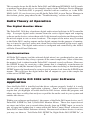
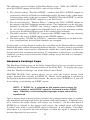
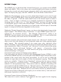
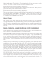
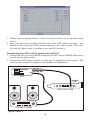
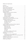
Delta DiO-2496 Manual
version: D2496-102799
Table of Contents
Introduction . . . . . . . . . . . . . . . . . . . . . . . . . . . . . . . . . . . . . . . . . . . . . . . . 2
What’s in the Box? . . . . . . . . . . . . . . . . . . . . . . . . . . . . . . . . . . . . . . . . . . . 2
About the Delta DiO 2496 . . . . . . . . . . . . . . . . . . . . . . . . . . . . . . . . . . . . . 2
Product Features & Specifications . . . . . . . . . . . . . . . . . . . . . . . . . . . . . . . 3
Minimum System Requirements
................................3
Quick Guide to Getting Started . . . . . . . . . . . . . . . . . . . . . . . . . . . . . . . . . 4
Hardware Installation . . . . . . . . . . . . . . . . . . . . . . . . . . . . . . . . . . . . . . . . . 5
Windows 95/98 Driver Software Installation . . . . . . . . . . . . . . . . . . . . . . . 6
Windows 98 Installation . . . . . . . . . . . . . . . . . . . . . . . . . . . . . . . . . . . 6
Windows 95 Installation . . . . . . . . . . . . . . . . . . . . . . . . . . . . . . . . . . . 7
Windows Driver Configuration
.................................7
Delta Theory of Operation . . . . . . . . . . . . . . . . . . . . . . . . . . . . . . . . . . . . . 8
The Digital Monitor Mixer . . . . . . . . . . . . . . . . . . . . . . . . . . . . . . . . . 8
Synchronization . . . . . . . . . . . . . . . . . . . . . . . . . . . . . . . . . . . . . . . . . 8
Using Delta DiO 2496 with your Software Application . . . . . . . . . . . . . . . 8
Delta DiO 2496 Control Panel Software . . . . . . . . . . . . . . . . . . . . . . . . . . . 9
Monitor Mixer Page . . . . . . . . . . . . . . . . . . . . . . . . . . . . . . . . . . . . . . 9
Patchbay/Router Page . . . . . . . . . . . . . . . . . . . . . . . . . . . . . . . . . . . . 11
Hardware Settings Page . . . . . . . . . . . . . . . . . . . . . . . . . . . . . . . . . . 12
S/PDIF Page . . . . . . . . . . . . . . . . . . . . . . . . . . . . . . . . . . . . . . . . . . . 14
About Page . . . . . . . . . . . . . . . . . . . . . . . . . . . . . . . . . . . . . . . . . . . . 15
Save, Delete, Load Buttons; H/W Installed . . . . . . . . . . . . . . . . . . . . . . . . 15
Typical Delta DiO Setup
. . . . . . . . . . . . . . . . . . . . . . . . . . . . . . . . . . . . . 16
Troubleshooting . . . . . . . . . . . . . . . . . . . . . . . . . . . . . . . . . . . . . . . . . . . . 20
Lifetime Limited Warranty . . . . . . . . . . . . . . . . . . . . . . . . . . . . . . . . . . . . 24
Introduction
Congratulations on your purchase of the Delta DiO 2496 digital audio interface card,
designed and built by M AudioTM. Even if you are experienced in digital recording,
please take the time to read this manual. It will give you valuable information on
installing your new card and the supporting software, plus help you to fully understand the function and usability of the Delta DiO 2496. Once you’re up and running,
you will quickly discover the Delta DiO 2496 is the backbone of your digital recording system.
What’s in the Box?
Your Delta DiO 2496 box contains:
•
This instruction manual
•
The Delta DiO 2496 adapter card
•
Driver diskette for Windows 95/98 installation, control panel software
•
M AudioTM warranty registration card
About the Delta DiO 2496
The Delta DiO 2496 Optical and Coaxial S/PDIF inputs and outputs give you the
highest quality digital I/O available- up to 24bit data width and any sampling rate
from 8kHz to 96kHz. Record a digital audio signal from your DAT, MiniDisc, CD,
or external A/D converter via one of the Delta DiO’s S/PDIF inputs and output to
both S/PDIF outputs. Monitor the inputs, or send the same or alternate mix to the
DiO’s 101dB S/N rated analog output. Control the routing with the Delta’s comprehensive control panel software.
The Delta DiO functions as a 2-input, 4-output card. The DiO accepts a stereo digital S/PDIF signal at one of its S/PDIF inputs at a time (the input is selected from the
Delta Control Panel software). Output-wise, a stereo digital S/PDIF signal is always
sent to both Coaxial and Optical S/PDIF outputs and another completely independent stereo stream is sent to the Delta DiO’s analog outputs.
Within the Delta DiO’s PCI chip is a hardware digital mixer. Controlled by the
included Delta Control Panel software, it may handle all of your routing needs,
giving you extra control of all left, right, and stereo levels, in addition to control of
pans, solos, and mutes.
2
Product Features & Specifications
•
2-in, 4-out 24-bit/96kHz full-duplex audio interface on a half-size PCI card.
•
S/PDIF inputs and outputs on Coaxial (gold-plated RCA) and Optical (TOSlink)
jacks.
•
High-quality stereo analog output on gold-plated RCA jacks, individually configurable for +4dB or -10dB signal levels.
•
Built-in digital mixer allows the D/A converter to monitor digital inputs, act as
its own independent stereo output, or as a mixture of both.
•
Measured D/A specs: 101dB (A-weighted) dynamic range, 0.002% THD @
0dBFS.
•
All data paths support up to 24-bit/96kHz performance.
•
PCI controller chip contains built-in digital mixer with 36-bit resolution.
•
Includes Windows 95/98, ASIO and Windows NT drivers.
Minimum System Requirements
•
•
•
•
Windows 95, 98 or NT 4
Pentium 200 MMX
64 MB of PC100 RAM
UDMA EIDE Hard disk
3
➊
➋
➌
➍
➎
The Delta DiO 2496 Adapter Card (Figure 1.)
1. Coaxial S/PDIF Input: This RCA connector receives a S/PDIF stereo signal from
your coaxial S/PDIF digital source.
2. Coaxial S/PDIF Output: This RCA connector sends a S/PDIF stereo signal to
your coaxial S/PDIF digital target device.
3. Optical S/PDIF Input: This TOSlink connector receives an optical S/PDIF stereo
signal from your optical S/PDIF digital source.
4. Optical S/PDIF Output: This TOSlink connector sends an optical S/PDIF stereo
signal to your optical S/PDIF digital target device.
5. Analog Audio Outputs (Left & Right): These RCA connectors carry the left and
right line-level signals to your monitoring or mix-down device. The signal levels for each output may be set to +4dBu or –10dBV via jumpers on the PCI card.
Quick Guide to Getting Started
Here is a list of the steps required to get your Delta DiO 2496 up and running:
1. Physically install the card in your computer (see ‘Hardware Installation’).
2. Start Windows and allow Windows’ Plug-and-Play to prompt you for the Delta
DiO drivers via the Add New Hardware wizard.
3. Install drivers and support software (see ‘Driver & Software Installation’).
4. Configure your digital recording software to select the Delta DiO 2496 as its
active audio input and output devices (see ‘Using Delta DiO 2496 with Software
Applications’ and also your applications software manual).
5. Hook up your digital audio gear (see ‘Typical Delta DiO Setup’).
4
Hardware Installation
NOTE: It is a good idea to make certain that an IRQ is available
for the Delta DiO 2496 to install to before proceeding, as resource
conflicts may cause a system to lock up. Open Control Panel |
System | Device Manager, then with "Computer" highlighted at
the top of the list, click Properties. This is a list of IRQs in use and
their related devices. The Delta DiO 2496 typically uses one of
these IRQ’s: 5, 7, 9-12, & 15. If a number does not show up in this
list, it means that it is available for use.
To mechanically install the Delta DiO 2496, do the following:
1. Turn off your computer.
2. Remove the computer’s cover and position the computer so that you may easily
access its PCI slots.
3. Select the PCI slot where you will install your Delta DiO card. Make sure it is
a PCI slot. If you don't know what "PCI slot" means, check the owner’s manual for your computer. PCI slots are distinguishable from ISA slots by being
shorter and set back farther from the outside of the computer, however some
newer computers have only PCI slots.
4. Before removing the Delta DiO 2496 from its protective anti-static bag, touch the
metal power supply case of the computer in order to dissipate any static electricity your body may have accumulated. You might want to pick up a grounding wrist strap (available from electronics stores like Radio Shack) if you want
to be doubly sure you aren't carrying a static charge that could damage the card.
5. Remove the metal bracket that covers the access hole on the back of the computer. This bracket is usually fastened to the computer with a single screw.
6. Remove the Delta DiO 2496 from its anti-static bag. In the lower lefthand corner you will see two (2) jumpers, one for the left and one for the right analog outputs. These jumpers control the operating line level of the DiO’s analog outputs.
With jumpers on (default), line level is set to -10dB (fine for consumer audio
equipment). Remove these jumpers if you wish to operate the analog outputs at
+ 4dB (better for pro audio equipment).
7. Position the Delta DiO 2496 card over the target PCI slot and fit the card loosely over it with the Delta DiO card upright. Press the card gently but firmly downward into the slot until the card is completely and squarely seated in the slot. If
the card seems difficult to seat, a slight rocking motion may help.
8. Screw the Delta DiO 2496 metal bracket down into the screw hole on the back
of your computer using the screw you removed in step 5 above.
9. Place the cover back on your computer.
5
Windows 95/98 Driver Software Installation
Included with the Delta DiO 2496 is a series of Windows driver diskettes, containing the Windows drivers and control panel software. To install the Windows drivers,
please follow these steps:
Windows 98 Installation
1. After installing the Delta DiO hardware, boot your system and start Windows.
During the Windows boot procedure, new hardware will be automatically detected by the Add New Hardware Wizard as shown here. Click ‘Next>’.
2. The ‘Add New Hardware Wizard’ will now ask how you want to find the driver.
"Search for the best driver for your device" is already selected. Click ‘Next>’.
3. Windows will give you a selection of locations to search. Make sure that ‘Floppy
disk drives’ is checked, or click on the check box to do so. Insert the Delta DiO
95/98 Driver Software disk into your floppy drive. Click ‘Next>’.
4. The ‘Wizard’ reports that its Windows driver file search has found the M Audio
Delta DiO. Click Next>.
5. Windows is now ready to install the driver files from the specified location.
Click Next>. Windows will start to copy the files and show you a progress report
screen.
6. The Wizard reports that Windows has finished installing the software. Click
‘Finish’. Your Delta DiO is ready for action.
After completion of the driver installation, Windows 98 may require you to restart
Windows. If it does request a restart, remove the floppy disk from drive A: and
respond "yes." The system will restart and your Delta DiO is ready for play!
6
Windows 95 Installation
1.
2.
3.
4.
After installation of the Delta DiO hardware, boot your system and start
Windows. During the Windows boot procedure, new hardware will be
automatically detected.
Choose the Install of "driver from disk provided by hardware manufacturer," then click OK.
An ‘Install From Disk’ will prompt you to copy files from the A:\ drive
(if your floppy drive is a different drive letter, then change it at this
time). Insert the Delta DiO 95/98 Driver Software disk #1 into the drive,
then click OK.
Windows will start to copy files, with a progress indicator on the screen.
Insert disks in numbered succession when prompted, clicking OK to
each new disk. Once this process completes itself, your Delta DiO will
be ready for action.
After completion of the driver installation, Windows 95 may require you to restart
Windows. If it does request a restart, remove the floppy disk from drive A: and
respond "yes." The system will restart and your Delta DiO is ready for play!
Windows Driver Configuration
Windows displays the Delta DiO driver status in the Device Manager page of the
System Properties dialog box. The Systems Properties dialog is opened via the
Windows Start button. Select Settings | Control Panel to open the Windows Control
Panel. Select "System" from the Control Panel to open the System Properties dialog box, then click on the "+" next to Sound, video and game controllers to open the
list of devices, the Delta DiO being a device of that nature. Below is an example
view of the Device Manager device list.
7
This example shows the M Audio Delta DiO and Midiman WINMAN 4x4/S (another product shown here only as an example) entries in the Windows Device Manager
device list. The Delta DiO is properly installed with no conflicts, as is the WINMAN 4x4/S. If you do not see your M Audio Delta DiO in your Device Manager in
this fashion, please jump ahead to the "Troubleshooting" section of this manual.
Delta Theory of Operation
The Digital Monitor Mixer
The Delta DiO 2496 has a hardware digital audio mixer built into its PCI controller
chip. It accepts digital audio streams from the active digital input and outgoing
software audio devices, mixes them with 36-bit internal resolution and then provides
the mixed output to one or more locations. The output of the mixer may be routed
to the Delta DiO’s analog outputs and/or digital outputs for the purpose of monitoring, or it may be used as a stereo mix-down device and recorded by the user’s application software. The digital audio mixer is configured and controlled by the included Delta Control Panel Software.
Synchronization
All Delta DiO outputs (and the onboard digital mixer) are synchronized to one master clock. Therefore they always operate at the same sample rate. Most of the time,
the master clock is taken from the Delta DiO’s internal crystal oscillators. However,
the S/PDIF In may be receiving a data stream that is completely asynchronous to
(not in sync with) the internal crystals. Therefore when recording or monitoring the
S/PDIF inputs, the board must be set up to get its master clock from the S/PDIF input
stream. This will force the digital mixer and all outputs to sync to the sample rate
of the active S/PDIF input.
Using Delta DiO 2496 with your Software
Application
Once the Delta DiO is installed and the driver software properly loaded, it is ready
for use with your music application software. Some of these applications will
require that you highlight or enable the Delta DiO drivers within the program, and
others may have a utility that analyzes or profiles the audio cards in your system and
enables the drivers.
Within your software application(s), the names of the Delta DiO input devices are 1)
Delta-DiO S/PDIF In, and 2) Delta-DiO Monitor Mixer. These two input devices
are stereo and allow you to record either directly from an S/PDIF input, or record a
mix of input and output that is setup within the Delta Control Panel software (see
Delta DiO Control Panel Software section). Because each of these devices is stereo,
you may see them as "Left Delta-DiO S/PDIF In, Right Delta-DiO S/PDIF In", or
8
"Left Delta-DiO Monitor Mixer, Right Delta-DiO Monitor Mixer" when selected in
your recording software.
The Delta DiO’s output devices are named 1) Delta-DiO WavOut 1/2, which is the
DiO’s analog output, and 2) Delta-DiO WavOut S/PDIF, which is both the coaxial
and optical S/PDIF outputs wired in parallel. Analog and S/PDIF digital devices
may be used at the same time for a total of 4 output channels. Because each device
is stereo, you may see "left" and "right" references within your software application.
This allows the application to pan audio left and right under software control.
Windows may be set up to use the Delta DiO as its default sound card. This allows
you to use the DiO with the sound applets included with Windows, and also enables
system sounds to be sent to the Delta DiO. To accomplish this, go to Control Panel
| Multimedia. In the Audio Properties page, set the Playback and Record devices to
the Delta DiO input and output devices of your choice.
Delta DiO 2496 Control Panel Software
Once your Delta DiO 2496 is properly installed in your system, you will see a "M
Audio Delta H/W" icon in your Windows Control Panel. You can launch the control panel software by double clicking on that icon. You can also create a shortcut to
it by clicking on the "M Audio Delta H/W" icon and dragging it to the desktop. A
dialog box will ask you if you wish to create a shortcut - click on ‘Yes’.
PLEASE NOTE: "Delta" represents a family of audio products from M Audio, and
the Delta Control Panel software is used by all audio cards in the Delta line.
Therefore, certain functions that do not apply to the Delta DiO 2496 will appear to
be "grayed out" in your Delta Control Panel software -- this is normal.
Monitor Mixer Page
The Monitor Mixer is the first page that appears when you open your Delta Control
Panel software. This page controls the digital mixer built into the Delta DiO’s PCI
controller chip. The output of this mixer may be assigned to hardware outputs, and
it may also be recorded as a stereo mix-down device by software.
9
MASTER VOLUME: At the left side of the Monitor Mixer page, you will see the
left and right ‘Master Volume’ faders. These faders control the overall volume of the
mixer output and have the longest ‘throw’ and highest meter resolution of any level
controls in the mixer page. The volume level faders may be controlled individually
by dragging the fader ‘handle’ vertically with the mouse. The default fader setting
is 0dB, or ‘Unity Gain’. Only attenuation is possible through lowered fader settings,
as there is no gain inherent to any of the faders.
NOTE: All Control Panel meters are color-coded in three sections:
green, yellow and red. The green section represents a safe zone,
ranging from the lowest detectable signal level to -12dB (12dB
below full-scale). Most audio signals should appropriately fill this
section of the meter. The yellow section ranges from -12dB to 2dB as the signal approaches a ‘hotter’ level. For best capture
resolution, recording in this area is both safe and advised. The
red section of the level indicator ranges from –3dB to 0dB. On the
input level meters, a 0dB condition indicates overload and audio
clipping may occur. Therefore be careful to adjust the incoming
audio levels so that they do not peak in the red section too long
(you might use the monitoring capability of the Delta DiO to let
your ears be the judge). On all output level meters, 0dB indicates
full-scale output -- clipping is impossible on the outputs because
of the 36-bit resolution built into the mixer hardware.
MIXER INPUTS: The Mixer Inputs are inputs to the monitor mixer. These inputs
are hardware audio streams and software audio streams, combined to make the monitor mixer extremely flexible. The leftmost input meters are labeled "WavOut 1/2"
and indicate the current audio levels being sent from your software application to the
analog output device. The next set of meters to the right are labeled "WavOut
S/PDIF" and indicate the current audio levels being sent from your software application to the S/PDIF digital output device. Finally, the rightmost pair of meters is
labeled "H/W In S/PDIF" and indicate the current audio levels at the active hardware
S/PDIF input. Only one of the S/PDIF inputs may be selected and used at a time.
This selection is made in the "S/PDIF" page of the control panel, covered in the later
S/PDIF section.
Each set of input channels has independent faders to control its own attenuation.
Also note that each "left" and "right" channel of the pair may be individually panned
anywhere in the stereo output mix. Clicking on the pan control handle and dragging
inward will bring that signal toward the center position of the stereo image all of the
way to the opposite pan position. The pan position value will be represented in the
Master Volume’s status box as a percentage from left pan to right pan of –100% to
+100%, 0% being center.
SOLO: Each Mixer Input channel has a "Solo" checkbox associated with it.
Clicking on and checking a Solo box will solo that selected channel by essentially
muting all other signals. When more than one channel has solo selected, all solo
10
channels will be summed to the solo ‘buss’ (path), which is what one might consider an ‘in place’ solo as opposed to a PFL, or pre-fader listen (levels and pans still
apply). Unchecking all solo boxes will again send all signals to both output paths
(analog and S/PDIF).
MUTE: Every channel has a "Mute" checkbox associated with it. Clicking on and
checking the Mute box will remove that signal from the stereo buss. Unchecking the
box will add the signal back into the stereo buss.
STEREO GANG: All channel pairs on this page have a "Stereo Gang" capability.
Clicking on and checking the Stereo Gang checkbox will link (or "gang") the
left/right faders so that both channels may be adjusted together as a stereo pair.
Patchbay/Router Page
The Patchbay/Router page allows you to select the source signal for each of the
Delta DiO’s 2 stereo outputs -- Analog or S/PDIF. To display this page, click the
"Patchbay/Router" tab of the Delta Control Panel.
The leftmost vertical column of Patchbay/Router page, "H/W Out 1/2," connects the
analog outputs of the DiO to one of four sources:
1. The default setting, "WavOut 1/2", connects the DiO’s analog outputs to your
music software or Windows multimedia applet. In other words, when music
software plays audio to the device named "Delta-DiO WavOut 1/2" it will be
routed directly to the analog outputs of your DiO board.
2. The second selection, "Monitor Mixer", connects the DiO’s analog outputs to the
output of the DiO hardware monitor mixer. This output mix can be any combination of software "S/PDIF" and "analog" outputs plus the hardware S/PDIF In.
All of these signal paths have adjustable level, pan, solo, and mute controls as set
up in the Monitor Mixer page of the control panel software.
3. The third selection, "S/PDIF In", connects the S/PDIF input (the one currently
selected as the active S/PDIF input) to the analog outputs. The left channel of
the S/PDIF In is routed to the left analog output and the right channel of the
S/PDIF In is routed to the right analog output.
4. The final option, "S/PDIF In (L/R Rev.)", functions identically to the third selection, except that the left and right channels are swapped. Therefore in this mode,
the left channel of the S/PDIF In is routed to the right analog output and the right
channel of the S/PDIF In is routed to the left analog output.
11
The rightmost vertical column of Patchbay/Router page, "H/W Out S/PDIF," connects the S/PDIF outputs of the DiO to one of four sources:
1. The default setting, "WavOut S/PDIF", connects the DiO’s S/PDIF outputs to
your music software or Windows multimedia applet. In other words, when music
software plays audio to the device named "Delta-DiO WavOut S/PDIF" it will be
routed directly to the S/PDIF outputs of your DiO board.
2. The second selection, "Monitor Mixer", connects the DiO’s S/PDIF outputs to
the output of the DiO hardware monitor mixer. This output mix can be any combination of software "S/PDIF" and "analog" outputs plus the hardware S/PDIF
In. All of these signal paths have adjustable level, pan, solo, and mute controls
as set up in the Monitor Mixer page of the control panel software.
3. The third selection, "S/PDIF In", connects the S/PDIF input (the one currently
selected as the active S/PDIF input) to the S/PDIF outputs.
4. The final option, "S/PDIF In (L/R Rev.)", functions identically to the third selection, except that the left and right channels are swapped.
At this point, you may begin to realize the versatility of the Monitor Mixer and the
Patchbay/Router, and the relationship between the two. You may want to re-read this
section and make some practice adjustments within the control panel software to
become proficient in routing and mixing. If somewhere in the process you become
confused, you may always restore the default settings to use the card as a straight 2in 4-out device.
Hardware Settings Page
The Hardware Settings page of the Delta Control Panel gives you control over miscellaneous hardware and software features of the Delta DiO. To display this page,
click the "Hardware Settings" tab of the Delta Control Panel.
MASTER CLOCK: This section allows you to select the board’s master clock
source: Internal Xtal (crystal) or S/PDIF In. Master clock operation is outlined in
the Synchronization section of this manual. Be sure to select "S/PDIF In" if you will
be recording or monitoring an S/PDIF stream.
NOTE: If "S/PDIF In" is selected as the master clock source, be
sure to supply a valid S/PDIF signal to the board’s active S/PDIF
input. Otherwise, erratic timing and improper sample rates will be
experienced.
Once a master clock source has been selected, its synchronization status is continually monitored and displayed below the master clock radio buttons. If internal crystal is selected, the status display will always say "Locked." On the other hand, if
S/PDIF In is selected as the master clock source, the control panel will display
"Locked" only when a valid S/PDIF signal is detected. It will display "Unlocked"
when there is no signal at the selected input, or when the signal is corrupt or has
become degraded for any reason.
12
CODEC SAMPLE RATE: This section is enabled only when the board is set to use
the internal crystal (Internal Xtal) as the source of its master clock. It is disabled
(greyed-out) when the master clock is set to S/PDIF In. This section indicates the
present board sample rate, as set by application software. The sample rate selected
here will be used to drive the digital mixer and all outputs. The "Rate Locked"
checkbox is used to force a sample rate upon the system. It is disabled by default to
allow software access to all supported sample rates. When checked, it causes the
driver to only operate at the selected sample rate. This means that any application
that attempts to open the Delta DiO driver at a sample rate other than the one selected here will fail to do so. "Reset Rate When Idle" is selected when you want the
sample rate to return to a particular setting when a software application is not actively using the board. This is particularly handy for keeping the digital mixer running
at a specific rate.
NOTE: Because the digital monitor mixer runs at the sample rate
of the rest of the board, and because sample rate directly affects
frequency response, it may be desirable to keep the sample rate
at or above 44.1 kHz while using the monitor mixer. This is
accomplished by enabling "Reset Rate When Idle" and selecting
a sample rate of 44.1 kHz or greater.
S/PDIF SAMPLE RATE: This section is enabled only when the board is set to use
S/PDIF In as the source of its master clock. It is disabled (greyed-out) when the
master clock is set to internal crystal. When S/PDIF In is used as the master clock,
the software applications need to be manually informed of the S/PDIF Input sample
rate. You should select the sample rate closest to that of the S/PDIF source. While
‘S/PDIF In’ is the master clock source, and you have a sample rate selected here, the
software application(s) using the Delta DiO will be prevented from selecting any
other sample rate.
NOTE: When S/PDIF In is the master clock source, the digital monitor mixer will run at the sample rate received at the S/PDIF In.
This may or may not adversely affect the frequency response of
the digital mixer.
MULTITRACK DRIVER DEVICES: The Delta DiO drivers are intelligent enough
to synchronize the beginning of recording and playback across all audio devices on
the board. When using application software that is capable of using multiple channels simultaneously, select "Single and In-Sync" to ensure that all four output channels will begin playback at the same time. Otherwise select "Independent" to allow
the output channels to play independently. This may be desirable if more than one
application needs to access different DiO channels at the same time.
DMA BUFFER SIZES: This section allows you to specify the amount of system
memory dedicated to buffering digital audio. Setting a buffer size that is too small
may result in clicks or pops in the audio stream as some data may be lost. Larger
buffers cause slightly more latency but prevent the pops and clicks that might occur
with smaller buffer sizes – the default settings are recommended but you may desire
to tweak these default settings to suit your tastes.
13
S/PDIF Page
The S/PDIF page of the Delta DiO Control Panel gives you control of the S/PDIF
inputs and outputs. This is also where you set up the digital audio format, and select
between the coaxial and optical inputs, choosing which is the current active digital
input. To display this page, click the "S/PDIF" tab of the Delta Control Panel.
Within the "Digital Input" group, you select which digital input is active, the Coaxial
(RCA) or Optical S/PDIF input. Only one digital input may be active at a time while
the other is ignored. Click the radio button next to the desired input to make it
active. Once an input is selected, it is constantly monitored to determine if the
incoming data is valid or not. A "Valid Input Detected" message will appear when
a valid digital signal is seen at the selected input. Conversely, the message "Invalid
or Not Present" will appear when there is no signal at the selected input, or when the
signal is corrupt or has become degraded for any reason.
Within the "Digital Output Format" group, you choose the digital audio format of the
digital outputs. The default setting, "Consumer," is a true S/PDIF format and is recognized by all consumer devices. The alternate "Professional" setting is an
AES/EBU type bit stream, but electrically it is S/PDIF. This is a work-around that
works successfully with some but not all AES/EBU devices.
For both consumer and professional output formats, the "Advanced" checkbox will
allow you to force the settings of a few particular status bits in the outgoing digital
audio stream. The advanced option is for expert users only; otherwise select
"Restore Defaults" to allow the Delta DiO drivers to handle the default status bit settings automatically. When "Consumer" and "Advanced" are both selected, the group
"Consumer Format Advanced Settings" will appear.
Conversely when
"Professional" and "Advanced" are both selected, the group "Professional Format
Advanced Settings" will appear.
Consumer Format Advanced Settings (Copy Mode):
Copy protection, also known as Serial Copy Management System (SCMS), is written into the S/PDIF subcode, a reserved part of the S/PDIF digital stream that is independent of the actual audio data being transmitted. It can be used to inhibit the
amount of copies that can be made, or allow for unlimited copying. Three SCMS
modes are available. "Original (Copy Permitted)" indicates that the source material
may be copied by a receiving device. "1st Generation" indicates that the source
material is a first generation copy. Most devices that are capable of recording will
reject material with this SCMS mode set. The final option is "No SCMS" which may
be used to override the other two modes and allow a recording device to successfully record the audio data. Different devices and similar devices by different manufacturers may behave differently and require you to set these bits by "trial-and-error"
until proper operation is achieved.
Consumer Format Advanced Settings (Emphasis):
This status bit is used to indicate if pre-emphasis has been applied to the outgoing
14
digital audio signal. The default is "None" and rarely will any user want to set the
value to "50/15uSec" which indicates an S/PDIF emphasis mode.
Professional Format Advanced Settings (Data Type):
The user may assign the outgoing data as audio or non-audio data. Many devices
ignore this setting. The obvious default is "audio."
Professional Format Advanced Settings (Emphasis):
The user may choose to indicate or not indicate if pre-emphasis has been applied to
the outgoing digital audio signal. The default is "None" and rarely will any user
want to set the value to "CCITT" or "50/15uSec" which are the two types of emphasis available in the AES/EBU status block.
About Page
The "About" page, while displaying the handsome M Audio logo and applicable
copyright information, also reports the driver version and control panel software version. If you have internet browsing capabilities and are currently connected to the
internet, clicking on the Midiman copyright will link you to the M Audio / Midiman
web site.
Save, Delete, Load Buttons; H/W Installed
At the rightmost side of the Delta Control Panel are the Save, Load and Delete buttons as well as an "installed hardware" set of radio buttons.
SAVE, DELETE, LOAD: The Delta Control Panel will retain the last settings that
were entered, except for mixer channels with solo settings -- they will default back
to ‘on’, and not to solo or muted. However the Save, Delete, and Load functions will
allow you to store different sets of control panel settings under different configuration file names. These configurations are then available for recall at a later date and
time.
Clicking the ‘Save’ button brings up a dialog box prompting you to name the current
configuration. Once you have done this, click ‘OK’, and your control panel settings
have been saved to disk. If you decide that you no longer need a particular configuration, click the ‘Delete’ button. Highlight the name of the configuration file that
you wish to delete, and click the ‘OK’ button. To recall a set of saved control panel
settings, click the ‘Load’ button. Highlight the name of the configuration file that
you wish to recall, and click ‘OK’. Those settings will now appear in the Delta
Control Panel and the driver will automatically update the hardware.
H/W INSTALLED: Several Delta cards may be installed in a system at one time
(note: this option may not exist in the first release of Delta software drivers). This
section displays all (a maximum of four) installed Delta cards, and allows you to
select which particular card is under the control of the control panel software. To
15
select the current card under configuration, click the radio button to the left of the
desired card in the list.
Typical Delta DiO Setup
Now that we’ve visited the wondrous intricacies of the Delta Control Panel, let’s
look at a setup that involves a typical transfer of information from DAT to computer and back to DAT.
NOTE: Because improper connections can potentially make very
loud noises, it’s a good idea to have monitor levels down while
hooking up audio equipment -- you may even choose to turn your
computer off before making the connections.
In this example, we will connect a DAT to the Delta DiO card using coaxial S/PDIF
cables (typically, 75 ohm). We’ll also connect the DiO’s analog outputs to a sound
system for monitoring purposes. A setup like this might be used to transfer a number of mixes from a DAT into an audio editing program, performing the appropriate
edits, and then transferring the edited material back to DAT.
The example below may at first look long and laborious, but you will find that most
of the settings are factory defaults and will rarely need to be modified.
Coaxial
Out
DAT
Analog
Out
L
OUT
IN
OUT
IN
DELTA DiO 2496
SOUND SYSTEM
Typical Setup 1
16
S/PDIF
AUDIO
R
Coaxial
In
Transferring from DAT to DiO
1. Connect the DAT coaxial S/PDIF Output to the DiO coaxial S/PDIF Input using
a good quality digital cable.
2. Connect the DiO analog outputs to some type of amplified sound system. The
sound system should be equipped with speakers or headphones.
3. In order to verify proper S/PDIF Input routing, open the S/PDIF page of the
Delta Control Panel software. In the Digital Input section, select "Coax/RCA."
This will make the DiO’s coaxial S/PDIF input the currently active input.
4. Because you will be recording from an S/PDIF input, you will need to setup the
DiO board to synchronize its master clock with the S/PDIF input. To do this,
open the Hardware Settings page of the control panel software. Under Master
Clock, select "S/PDIF In."
5. Next, set the S/PDIF Sample Rate selection to match the sample rate of the DAT
digital audio. This information is necessary in order for your audio recording
software to know the expected sample rate. We use 44,100 in this example.
6. In order to monitor the digital signal coming into the DiO, open the
Patchbay/Router page of the control panel software. In the "H/W Out 1/2" column, select the radio button named "S/PDIF In." This will copy all S/PDIF input
audio over to the analog outputs.
17
7. Within your recording software, select "Delta-DiO S/PDIF In" as the audio input
device.
8. Start your software recording and then start your DAT material playing. You
should be able to hear the DAT material through your sound system. This verifies that the digital audio is making it into the DiO correctly.
Transferring from DiO to DAT, monitoring with DAT
1. Connect the DiO coaxial S/PDIF Output to the DAT coaxial S/PDIF Input using
a good quality digital cable.
2. Connect the DAT analog outputs to some type of amplified sound system. The
sound system should be equipped with speakers or headphones.
Coaxial In
Analog Out
DAT
Coaxial
Out
L
OUT
IN
OUT
DELTA DiO 2496
SOUND SYSTEM
Typical Setup 2
18
IN
S/PDIF
AUDIO
R
3. Because you will be playing back at the recorded sample rate, you will want to
set the DiO’s master clock to use the DiO internal crystal. Do this by opening
the Hardware Settings page of the Delta Control Panel software and under
Master Clock, selecting "Internal Xtal." Also, under the Codec Sample Rate section you may uncheck "Rate Locked" if it is previously checked. This allows for
more flexible sample rate playback.
4. In order to verify proper S/PDIF Output routing, open the Patchbay/Router page
of the control panel software. In the "H/W Out S/PDIF" column, select the radio
button named "WavOut S/PDIF." Now the outputs of your music software will
be sent to the DiO S/PDIF Out, and consequently to the DAT.
5. Next let’s make sure the S/PDIF output format is correct. Open the S/PDIF page
of the control panel software. Under Digital Output Format, choose "Consumer."
Uncheck "Advanced" if it is checked previously. Now click on the "Restore
Defaults" button to set the default S/PDIF outgoing status bits. This will disable
copy protection and also set the emphasis to "none," allowing the DAT to accept
and record the audio properly.
6. Within your recording software, select "Delta-DiO S/PDIF Out" as the audio output device.
7. Start your DAT recording and then start your software playing. You should be
able to hear the DAT material through your sound system. This verifies that the
digital audio is making it into the DAT correctly.
19
Troubleshooting
This section addresses potential problems that can occur in all operating system
environments, with emphasis on hardware troubleshooting. Within the PC environment there are a limited number of hardware resources (Addresses, IRQs, and DMA
channels) available for use. Since audio cards require many resources, most audio
card installation problems arise from unavailable or improperly set resources.
NOTE: The Delta DiO does not require any DMA channel
resources and requires only one IRQ.
If a device in Windows’ Device Manager list has a resource conflict with another
device, a yellow exclamation point will generally appear on top of the icon next to
that device. There can be several ways to approach this.
By highlighting an item with a problem, then clicking Properties (or double-clicking
the item), you will open up a properties sheet for that device. Selecting the
Resources tab from within the Properties dialog box will allow you to view
resources, plus view possible conflicts by highlighting each item (done by clicking
on it) one by one and examining the "Conflicting resource list:" at the bottom of the
box.
Sometimes it is possible that there is a resource problem that is not showing up in
the conflicting resource list or as a yellow exclamation point in the Device Manager.
If you have any doubt about the configuration of your device (or just want to double-check), you can view all of the devices and their associated IRQs by highlighting "Computer" at the top of the Device Manager list and clicking Properties (or
double-click "Computer"). This will present a dialog box with IRQ numbers on the
left, and devices on the right. An entry that reads "IRQ Holder for PCI Steering"
along with an installed PCI device (such as the Delta DiO) is normal. If you see
another device showing up on the same IRQ as the Delta DiO (such as a video card,
SCSI adapter, or USB Host Controller), then the Delta DiO has a conflict and most
likely is not working properly. As mentioned earlier, the Computer Properties list is
the best source of information to establish availability of resources. Clicking the
Input/Output (I/O) button at the top of the box will give you a list of Addresses in
use (as well as DMA channels, although none are being used on the Delta DiO).
Usually, there are not address problems with PnP devices, but one might note that an
address of 300h (the default address of the Winman 4X4/s, for instance), will read
"0300" in this list (it is a 16-bit hexadecimal representation).
20
If the Delta DiO has requested an IRQ in use by another PCI device, but there are
other IRQs available, moving the Delta DiO card to an alternate PCI slot may help.
Changing PCI slots will cause the PnP system to recognize the card as new hardware
and re-establish it with a different IRQ. Some newer BIOS (see your computer manual) allow the selection of an IRQ for each PCI slot on the motherboard. This can
be very handy in resolving IRQ assignments for PCI devices. However, if there are
no IRQs available, some kind of reconfiguring or reprioritizing your system is in
order. Optionally, a second hardware configuration can be created for running two
sets of hardware profiles. See your Windows documentation for help in this area.
NOTE: When resolving conflicts between PnP and non-PnP
devices, it is usually easier to re-adjust the resource settings of
the non-PnP device. Windows is only aware of the resource settings of the installed PnP devices and has no information available to it for adjusting the PnP devices around the non-PnP
devices. The exception to this is when a non-PnP device has a
true Windows 95/98 driver written for it, or if the BIOS allows
instructions for an IRQ to receive a legacy device as opposed to
a PnP device. In that case Windows is aware of the non-PnP
device’s resource requirements.
IMPORTANT: Most sound card installation problems result from
attempting to use system resources (IRQs, address locations)
already in use by other hardware or software in the system.
21
Problem: No Sound.
Possible Cause 1: There is a resource conflict with another device in
your computer. Check the Delta DiO 2496 configuration (Address, IRQ) against
those of the other devices on your computer. If necessary, change the settings for the
one or more of the devices
Possible Cause 2: The Delta DiO drivers are not properly installed or
are not selected as the current audio output device.
Possible Cause 3: Misrouted outputs in the Delta Control Panel.
Check the Patchbay/Router page of the control panel software to be sure the output
you are intending to use is connected to the desired audio source. Also make sure
that if the output is routed from the digital mixer, that the faders are set for proper
signal levels and not muted.
Possible Cause 4: Improper connections of the audio accessories.
Verify that the Analog Out is properly connected to a digital mix deck or external
mixer/amplifier, or the S/PDIF Out is connected to an external digital audio device
capable of receiving S/PDIF.
Problem: No visual activity on Audio Input volume (VU) meters.
Possible Cause 1: Wrong S/PDIF input (coaxial or optical) is selected
in the Delta Control Panel software.
Possible Cause 2: The Delta DiO input(s) are not properly selected in
the user’s application software.
Possible Cause 3: Improper connections to audio accessories.
Problem: Repetitious Sound.
Possible Cause: Wrong IRQ or IRQ resource conflict. Often this will
result in a small segment of sound (0.5 to 1 second) repeating itself over and over,
sometimes completely locking up the computer. See the general troubleshooting
suggestions at the beginning of this section.
Problem: A third-party Windows digital audio program does not play or
record to/from Delta DiO 2496.
Possible Cause 1: The Delta DiO 2496 Audio driver is not properly
installed. Install/reinstall all Delta DiO 2496 audio drivers (see Windows Software
section).
Possible Cause 2: You have not selected the Delta DiO audio driver
from your application. Many third-party applications require you to select a specific driver (because there can be more than one in an advanced system) for use with
the application. Select the input device named "Delta DiO S/PDIF In" and/or "Delta
DiO Monitor Mixer" as your active audio driver. The manner in which this selection is made is dependent on the application (each one is a little different).
22
Problem: I’m getting some pops and clicks in my audio recording.
Possible Solution: Some accelerated graphics cards use excessive
amounts of system bandwidth, preventing the recording buffer of an audio card from
keeping up with demand. This can cause clicks in the recording. This problem may
often be solved by reducing or turning off the graphics acceleration feature of the
graphics card. In Windows, this is accessed from Settings | Control Panel | System
| Performance | Graphics.
23
Lifetime Limited Warranty
MIDIMAN warrants that this product is free of defects in materials and
workmanship under normal use so long as the product is owned by the original purchaser and that purchaser has registered his/her ownership of the
product by sending in the completed warranty card.
In the event that MIDIMAN receives written notice of defects in materials or
workmanship from such an original purchaser, MIDIMAN will either
replace the product, repair the product, or refund the purchase price at its
option. In the event any repair is required, shipment to and from MIDIMAN
and a nominal handling charge shall be born by the purchaser. In the event
that repair is required, a Return Authorization number must be obtained
from MIDIMAN. After this number is obtained, the unit should be shipped
back to MIDIMAN in a protective package with a description of the problem
and the Return Authorization clearly written on the package.
In the event that MIDIMAN determines that the product requires repair
because of user misuse or regular wear, it will assess a fair repair or replacement fee. The customer will have the option to pay this fee and have the unit
repaired and returned, or not pay this fee and have the unit returned unrepaired.
The remedy for breach of this limited warranty shall not include any other
damages. MIDIMAN will not be liable for consequential, special, indirect, or
similar damages or claims including loss of profit or any other commercial,
damage, even if its agents have been advised of the possibility of such damages, and in no event will MIDIMAN’s liability for any damages to the purchaser or any other person exceed the price paid for the product, regardless
of any form of the claim. MIDIMAN specifically disclaims all other warranties, expressed or implied. Specifically, MIDIMAN makes no warranty
that the product is fit for any particular purpose.
This warranty shall be construed, interpreted, and governed by the laws of
the state of California. If any provision of this warranty is found void,
invalid or unenforceable, it will not affect the validity of the balance of the
warranty, which shall remain valid and enforceable according to its terms. In
the event any remedy hereunder is determined to have failed of its essential
purpose, all limitations of liability and exclusion of damages set forth herein shall remain in full force and effect.
24
DELDiO-102799