1
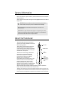
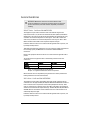
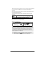
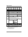
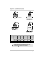
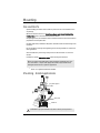
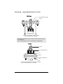
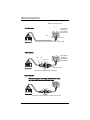
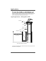
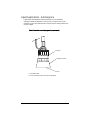
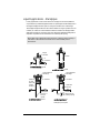
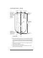
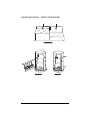
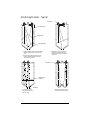
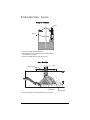
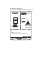
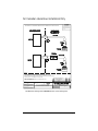
Instruction Manual
June 2002
XPS/XCTTRANSDUCERS
XPS/XCT SERIESTRANSDUCERS
Safety Guidelines
Warning notices must be observed to ensure personal safety as well as that of others, and to
protect the product and the connected equipment. These warning notices are accompanied
by a clarification of the level of caution to be observed.
Qualified Personnel
This device/system may only be set up and operated in conjunction with this manual.
Qualified personnel are only authorized to install and operate this equipment in accordance
with established safety practices and standards.
Warning: This product can only function properly and safely if it is correctly transported,
stored, installed, set up, operated, and maintained.
Note: Always use product in accordance with specifications.
Copyright Siemens Milltronics Process
Instruments Inc. 2002. All Rights Reserved
Disclaimer of Liability
This document is available in bound version and in
electronic version. We encourage users to
purchase authorized bound manuals, or to view
electronic versions as designed and authored by
Siemens Milltronics Process Instruments Inc.
Siemens Milltronics Process Instruments Inc. will
not be responsible for the contents of partial or
whole reproductions of either bound or electronic
versions.
While we have verified the contents of
this manual for agreement with the
instrumentation described, variations
remain possible. Thus we cannot
guarantee full agreement. The
contents of this manual are regularly
reviewed and corrections are included
in subsequent editions. We welcome
all suggestions for improvement.
Technical data subject to change.
MILLTRONICS®is a registered trademark of Siemens Milltronics Process Instruments Inc.
Contact SMPI Technical Publications at the following address:
Technical Publications
Siemens Milltronics Process Instruments Inc.
1954 Technology Drive, P.O. Box 4225
Peterborough, Ontario, Canada, K9J 7B1
Email: [email protected]
For the library of SMPI instruction manuals, visit our Web site: www.milltronics.com
© Siemens Milltronics Process Instruments Inc. 2002
General Information
Refer to this manual for proper installation, operation, and maintenance of the XPS/XCT
Series Transducers.
Special attention must be paid to warnings and notes highlighted from the rest of the text
by grey boxes.
WARNING means that failure to observe the necessary precautions can
result in death, serious injury, and/or considerable material damage.
Note means important information about the product or that part of the
operating manual.
IMPORTANT: All specifications are subject to change without notice.
Please ensure that any safety-related information is confirmed with
a qualified Siemens Milltronics representative.
About the Transducer
The Echomax XPS / XCT series of transducers
operates in association with Milltronics ultrasonic
level monitoring products.
The transducer converts the electrical energy of
the transmit pulse from the transceiver into
acoustical energy. It then converts the acoustical
energy of the echo back into electrical energy for
the transceiver receive period.
transducer
transducer face
–3 db
The effective acoustical energy is emitted from
boundary
the transducer face and radiated outward,
decreasing in amplitude at a rate inversely
proportional to the square of the distance.
axis of
Maximum power is radiated axially
transmission,
perpendicular
(perpendicular) from the transducer face in a line
to transducer
referred to as the axis of transmission. Where
face
power is reduced by half (– 3 dB), a conical
boundary defining the sound beam, centered
about the axis of transmission, is established. The
diametric measurement of the cone in degrees
defines the beam angle. Impedance matching techniques are used to optimize the
transfer of power from the transducer into air and vice versa.
The XPS / XCT transducers incorporate an integral temperature sensor that reports the
air temperature at the transducer to the transceiver. The connection is transparent, in that
both the ultrasonic and temperature components of the transducer use the same leads.
7ML19981AK01
XPS/XCT Transducers– INSTRUCTION MANUAL
Page 1
General Guidelines
WARNING: Materials of construction are chosen based on their
chemical compatibility (or inertness) for general purposes. For exposure to
specific environments, check with chemical compatibility charts before
installing.
XPS/XCT Series - Certificate SIRA 99ATEX5153X
This equipment may be used in hazardous areas associated with all gases with
temperature classes T1, T2, T3 and T4 for the XPS series (XPS-10, XPS-15, XPS-30 and
XPS-40) and T1, T2 and T3 for the XCT series (XCT-8 and XCT-12). The XPS series is only
certified for use in ambient temperatures in the range of - 40°C to 95°C and the XCT
series is only certified for use in ambient temperatures in the range of -40°C to 145°C.
Neither should be used outside of their respective temperature ranges.
Installation shall be carried out in accordance with the applicable code of practice, and
by suitably trained personnel.
These devices should only be supplied from a circuit containing a suitably-rated fuse that
has a breaking capacity of 4000A. This fuse is included in Siemens Milltronics’
transceivers.
Repair of this equipment shall be carried out in accordance with the applicable code of
practice.
The certification of this equipment relies on the following materials used in their
construction:
Material
XPS Series
Enclosure
Kynar®1710
Kynar®710
Encapsulant
Stycast LA-9823-76
Durapot® 861-F3 & 864
1.
XCT Series
Kynar®is a registered trademark of ELF Atochem.
Durapot®is a registered trademark of Cotronics Corporation.
Manual override can be accomplished by using the disconnect switch provided in the
building installation of the associated controller.
XPS D Series - Certificate SIRA 01ATEX5262X
This equipment may be used in all hazardous dust zones with all conductive and nonconductive dusts. The Type XPS-10D, XPS-15D, XPS-30D and XPS-40D Series transducers
have a maximum surface temperature of 135°C (275°F) (Temperature Class T4). These
units are certified for use in ambient range of -40 to 95°C (-40 to 203°F). The transducers
should not be used outside this temperature range. The XPS-10D, XPS-15D, XPS-30D and
XPS-40D Ultrasonic Transducers must be installed so the face of the transducer is not
substantially subjected to light.
Installation shall be carried out in accordance with the applicable code of practice, and
by suitably trained personnel.
Page 2
XPS/XCT Transducers– INSTRUCTION MANUAL
7ML19981AK01
These devices should only be supplied from a circuit containing a suitably rated fuse that
has a breaking capacity of 4000A. This fuse is included in Siemens Milltronics
transceivers.
Repair of the equipment shall be carried out in accordance with the applicable code of
practice and Installation Instructions.
The certification of this equipment relies on the following materials used in their
construction:
Enclosure
Kynar® complete with carbon nanotube (Polyvinylidene Flouride
(PVDF) with carbon nanotube [RTP Part No. 3399 X 93208 E]).
Encapsulant
Stycast LA-9823-76 or Durapot® 864 (as appropriate)
Manual override can be accomplished by using the disconnect switch provided in the
building installation of the associated controller.
XPS D Series Product Marking
PETERBOROUGH, CANADA
XPS-xxD
ULTRASONIC TRANSDUCER
SERIAL No.:
V IN : 1.77 V r.m.s.; 250 Vp
I IN : 44.2 mA r.m.s.
AMBIENT TEMP.: –40 C TO 95 C .
0518
SIEMENS MILLTRONICS PROCESS INSTRUMENTS INC. PETERBOROUGH
SIRA 01ATEX5262X
SEE INSTRUCTION MANUAL FOR OPERATION.
Note: Kynar® polyvinylidene flouride is resistant to attack from most chemicals
under the described operating conditions. However, for exposure to specific
environments, check with chemical compatibility charts before installing the
XPS/XCT Transducers in your application.
WARNING: This product is designated as a Pressure Accessory per
Directive 97/23/EC and is not intended for use as a safety device.
7ML19981AK01
XPS/XCT Transducers– INSTRUCTION MANUAL
Page 3
Specifications
Model :
Measurement
Range,
m (ft):
XPS - 10
XPS - 15
XPS - 30
XPS - 40
XCT - 8
XCT - 12
0.3 - 10
0.3 - 15
0.6 - 30
0.9 - 40
0.6 - 8
0.6 - 12
(1-33)
(1-50)
(2-100)
(3-130)
(2-26)
(2-40)
Frequency (kHz):
44
44
30
22
44
44
Beam Angle:
12°
6°
6°
6°
12°
6°
Environmental:
-location:
indoor / outdoor
-altitude:
2000 m maximum
-ambient
temperature:
-40 to 95 °C (-40 to 203 °F)
-pollution
degree:
-40 to 145 °C (-40 to 293 °F)
4
Construction:
Kynar®
-exposure:
-mounting:
1" NPT or BSP conduit connection
Standard: Kynar®
Optional: Universal*** sized flange
available with Teflon® facing
1-1/2” NPT or BSP conduit connection
1” NPT or BSP conduit connection
» factory bonded to suit ANSI, DIN and JIS standards
» polyethylene foam facing for dusty or steamy environments
-options:
» submergence shield, where flooding can occur (only available for XPS-10, XPS-15)
» split flange for field mounting to suit ANSI, DIN and JIS standards (not available for XPS-40)
Included:
2-wire twisted pair / braided and foil shielded, 0.5mm² (20 AWG), PVC
jacket
2-wire twisted pair / braided and
foil shielded, 0.5mm² (20 AWG),
PVC jacket
-cable:
Maximum separation:
100 m (330 ft)
Silicone jacket
RG-62 A/U coax
Maximum separation:
365 m (1200 ft)
Supply Source:
Weight*, kg (lb):
transducer shall only be supplied by Milltronics certified controllers
0.8 (1.7)
1.3 (2.8)
4.3 (9.5)
8 (18)
0.8 (1.7)
Separation:
365 m (1200 ft) from transducer
Approvals:
CE **, CSA, FM, CENELEC/ATEX
see nameplate or consult Milltronics for current approvals
1.3 (2.8)
* approximate shipping weight of transducer with standard cable length
** EMC performance available upon request
***Universal flange fits ANSI, DIN, and JIS standards.
Kynar® is registered trademark of ELF Atochem
Teflon® is a registered trademark of DuPont
Page 4
XPS/XCT Transducers– INSTRUCTION MANUAL
7ML19981AK01
Outline and Dimensions
B
B
radiating face
A
C
standard
optional bonded flange
refer to associated instructions
D
F
C
optional split flange
refer to associated instructions
E
optional submergence shield
refer to associated instructions
Model
Dimension
XPS 10
XPS - 15
A
86 mm (3.4")
119 mm (4.7") 173 mm (6.8") 206 mm (8.1") 86 mm (3.4")
XPS - 30
XPS - 40
XCT - 8
XCT - 12
119 mm (4.7")
B
122 mm (4.8") 132 mm (5.2") 198 mm (7.8") 229 mm (9.0") 122 mm (4.8") 132 mm (5.2")
C
to suit ANSI, DIN and JIS standards
D*
128 mm (5.0") 138 mm (5.4") 204 mm (8.0") 235 mm (9.2") 128 mm (5.0") 138 mm (5.4")
E
124 mm (4.9") 158 mm (6.2") n / a
n/a
n/a
n/a
F
152 mm (6.0") 198 mm (7.8") n / a
n/a
n/a
n/a
* nominal
WARNING; Optional Split Flange, Bonded Flange, and Easy Aimer
configurations are not suitable for pressure applications.
7ML19981AK01
XPS/XCT Transducers– INSTRUCTION MANUAL
Page 5
Mounting
Dos and Don’ts
Special handling precautions must be taken to protect the face of the transducer from
any damage.
Mount the transducer so that it is above the maximum material level by at least the
blanking value. Refer to the associated transceiver manual.
On liquid applications, the transducer must be mounted so that the axis of transmission is
perpendicular to the liquid surface.
On solids applications, a Milltronics Easy Aimer should be used to facilitate aiming of the
transducer.
Do not overtighten mounting. Hand tightening of the mounting hardware is sufficient for
most applications.
Secure installation by connecting a safety chain from the transducer to a structural
member.
Consider the optional temperature sensor when mounting the transducer.
Note: For pressure tight applications, install transducers hand tight plus ½ turn
to 1½ turns. Teflon®1 tape or other appropriate sealant may be used to aid in
sealing the threads for use in pressure applications.
1.
Teflon®is a registered trademark of DuPont.
Mounting - Solids Applications
Easy Aimer (typical
model)
safety chain
transducer
WARNING: Improper installation may result in loss of process pressure.
Page 6
XPS/XCT Transducers– INSTRUCTION MANUAL
7ML19981AK01
Mounting - Liquid Applications
Flexible Conduit
Bracket
flexible
conduit
steel channel
coupling
safety
chain
transducer
Flexible conduit mounted transducer should
not be subjected to wind, vibration or jarring.
Submersible
Plywood
rigid metal conduit
coupling
safety
chain
submergence
shield
Submersible transducer, used in
applications where flooding is possible.
7ML19981AK01
Plywood mounting provides excellent
isolation, but must be rigid enough to
avoid flexing if subjected to loading.
XPS/XCT Transducers– INSTRUCTION MANUAL
Page 7
Mounting - Liquid Applications (cont’d)
Blind Flange
nipple welded to blind flange
coupling
Flange, gasket and hardware supplied by customer.
Refer to Liquid Applications - Standpipes
Note: Tighten the flange bolts evenly in order to ensure a good seal between
the mating flanges.
Caution: Overtightening can cause performance degradation.
Flanged
coupling
factory flanged transducer
bolt
gasket
customer flange, flat face
only
nut
Customer flanged standpipe. If a metal flange must be welded
to pipe, refer to Liquid Applications - Standpipes.
Page 8
XPS/XCT Transducers– INSTRUCTION MANUAL
7ML19981AK01
Interconnection
Milltronics transceiver (typical)
b
l
k
/
h
o
t
Direct Connection
w
h
t
/
s
h
l
d
For EnviroRanger
ERS 500 only,
connect all three
wires separately.
blk
wht
drain / shield
2 Wire Extension
wht
For EnviroRanger
ERS 500 only,
connect all three
wires separately.
blk
junction box
drain / shield
extend cable using 18 AWG shielded / twisted pair
Coaxial Extension
When connecting to an EnviroRanger 500, do NOT use coaxial
cable, use a 2-wire extension as illustrated above.
extend cable using RG - 62 A/U coax for optimum noise immunity
7ML19981AK01
XPS/XCT Transducers– INSTRUCTION MANUAL
Page 9
Dos and Don’ts
Installation shall only be performed by qualified personnel and in accordance with
local governing regulations.
Do not route cable openly.
For optimum isolation against electrical noise, run cable separately in a grounded metal
conduit.
Seal all thread connections to prevent ingress of moisture.
Do not run cable near high voltage or current runs, contactors and SCR control drives.
Note: For pressure tight applications, install transducers hand tight plus ½ turn
to 1½ turns. Teflon®tape or other appropriate sealant may be used to aid in
sealing the threads for use in pressure applications.
WARNING: Never attempt to loosen, remove, or disassemble process
connection while vessel contents are under pressure.
Page 10
XPS/XCT Transducers– INSTRUCTION MANUAL
7ML19981AK01
Applications
The transducer is to be used only in the manner outlined in this instruction manual.
Normally, the transducer requires no cleaning or maintenance. However, if performance
changes are observed, immediately shut down the level measurement system and
perform a thorough inspection, especially on the transducer.
Liquid Applications - Stilling Well / OCM
blind flange
air vent
TS-3*
transducer
standpipe
bracing
standpipe inlet
primary element
stilling well
stilling well inlet
Refer to Liquid \ Applications - Standpipes.
* the use of a TS-3 temperature sensor provides better temperature tracking in applications where
the temperature can change quickly.
7ML19981AK01
XPS/XCT Transducers– INSTRUCTION MANUAL
Page 11
Liquid Applications - Submergence
In applications where flooding is possible the transducer* can be fitted with a
submergence shield. The shield acts as a bell to create an air pocket in front of the
transducer face. The associated transceiver* interprets this as a flooding condition, and
reacts accordingly.
Refer to transceiver manual for programming requirements.
transducer
submergence shield**
air pocket
* on applicable models.
** refer to associated instruction manual for assembly details.
Page 12
XPS/XCT Transducers– INSTRUCTION MANUAL
7ML19981AK01
Liquid Applications - Standpipes
In many applications access must be made via a standpipe. In such cases, Milltronics
can provide factory bonded flanged transducers or split flange kit that will readily mate to
the flanged standpipe. Another option is to hang the transducer from a blind flange.
The standpipe length should be as short and the diameter as large as possible. As a rule
of thumb, the –3 dB cone of the sound beam should not intersect the standpipe wall in
applications opening into a vessel or larger area. Otherwise, additional blanking will be
required to compensate for the interference zone created by the opening.
Note: When using a stilling well, make sure there is no build-up, welds, couplings, or
other debris on the inside of the well wall. This can affect reliability of level
measurement.
flanged
transducer
no vessel
no
intersection
vessel
no additional blanking required
no additional blanking required
nipple welded into
blind flange
transducer
can read
level inside
or below
standpipe
transducer
transducer
sound beam
intersects
standpipe
end cut on a
45º angle
typically
no additional blanking required
7ML19981AK01
nipple welded into
blind flange
vessel
reflection at
interference zone
created by opening
near blanking extension of
150 mm (6") past end of
standpipe may be required.
XPS/XCT Transducers– INSTRUCTION MANUAL
Page 13
Liquid Applications - Volume
Acceptable
Preferred
Not Acceptable
Maintain full level
for full calibration.
Above this level
erroneous readings
will result as level
has entered
blanking zone.
(shaded area)
tank
manufacturer’s
full level
beam
angle
span: corresponds to
tank manufacturer’s
empty level.
rise
Empty level for
acceptable location.
Below this level, echo
would reflect away
from the transducer.
tank manufacturer’s
empty level
may require target to
obtain empty reading
discharge
1.
Beam should not detect bin bottom. If this occurs use range extension parameters
(on transceivers where available) to omit false echoes. A 6° beam angle represents
a rise : run of about 20 : 1 (10 : 1 for 12°). In most tanks, the transducer should be
centered as much as possible (without interference from inlet) for optimum reading
range.
2.
Sound beam must be perpendicular to liquid surface. If standpipe is used, refer to
Liquid Applications - Standpipes.
3.
Echo has missed improperly leveled transducer.
4.
When performing an empty or full calibration, the tank must contain its normal
vapour and be at its normal temperature.
Page 14
XPS/XCT Transducers– INSTRUCTION MANUAL
7ML19981AK01
Liquid Applications - Water / Wastewater
Differential Level
Pump Control
7ML19981AK01
Sewage Lift
XPS/XCT Transducers– INSTRUCTION MANUAL
Page 15
Solids Applications - Typical
Easy Aimer
1
bin wall seams
3
2
filling profile
emptying profile
1. Transducer angled to avoid seams in bin wall and
aimed at discharge in order to read bin when
empty.
2. Avoid intersecting bin wall seams, structural
members and wall irregularities. Otherwise,
refer to transceiver manual.
3. Transducer too close to material inlet.
Falling material will intersect sound
beam and cause erroneous readings or
loss of echo.
transducer
minimal angle
of repose
5
4
discharge
4. On fluid-like solids, aim
transducer perpendicular to
material surface.
Page 16
5. On dual discharge bins, aim each
transducer at the discharge point.
XPS/XCT Transducers– INSTRUCTION MANUAL
7ML19981AK01
Solids Applications - Special
Storage Bin with Agitator
infeed
3
2
1
agitator
1. Transducer should be kept away from infeed.
2. Where agitators are in use, use the Agitator Discrimination parameter
on transceivers where available.
3. Transducer should be aimed away from wall projections.
Dryer - Wood Chips
infeed
drag conveyor
typical low level
typical high level
5. Transducer should be mounted perpendicular to slope of wood chips.
7ML19981AK01
XPS/XCT Transducers– INSTRUCTION MANUAL
Page 17
Installation Diagram
IMPORTANT NOTICE
THIS DOCUMENT REMAINS THE PROPERTY OF MILLTRONICS AND IS
SUBJECT TO RECALL. IT MAY NOT BE COPIED, AND IS ISSUED
AND CAN BE UTILIZED ONLY FOR SUCH LIMITED PURPOSES AS MAY
SPECIFICALLY HAVE BEEN AUTHORIZED BY MILLTRONICS. IT IS
TO BE MAINTAINED CONFIDENTIAL, SINCE IT MAY CONTAIN
PROPRIETARY INFORMATION AND TRADE SECRETS OF MILLTRONICS
OR OTHERS. THE ITEMS DEPICTED MAY THEMSELVES BE THE
SUBJECT OF PATENTS, INDUSTRIAL DESIGN REGISTRATIONS OR
COPYRIGHTS OF MILLTRONICS OR OTHERS, AND THE ISSUE OF THIS
DRAWING DOES NOT IMPLY ANY LICENSE UNDER ANY SUCH RIGHTS.
COPYRIGHT MILLTRONICS
ALL RIGHTS RESERVED
SEE
NOTE 3
NOTES:
1) INSTALLATION SHALL BE DONE IN ACCORDANCE WITH
THE NATIONAL ELECTRICAL CODE (N.E.C.).
2) NO REVISION SHALL BE MADE WITHOUT PRIOR FMRC AUTHORIZATION.
3) USE N.R.T.L. LISTED WATER TIGHT CONDUIT FITTING FOR OUTDOOR APPLICATIONS.
DRAWING SCALE
DRAWN BY
NONE
TOLERANCES UNLESS OTHERWISE NOTED
0
FOR ISSUE
BG
No.
REVISION DESCRIPTION
DWG BY
1 PLACE DECIMAL
±0.030"
FRACTIONS
2 PLACE DECIMAL
3 PLACE DECIMAL
±0.010"
±0.002"
ANGLES
DATE
±0.5°
PETERBOROUGH, ONTARIO, CANADA.
PLOT AT
REV
DRAWING No.
FILE No.
APPROVED BY
AUG
13/96
±0.030"
TITLE
CHECKED BY
TV
APPRO.
THIRD ANGLE PROJECTION
0
1:1
SHEET
1
OF
1
See Milltronics drawing number 0-9650017Z-DI-A for current drawing status.
Page 18
XPS/XCT Transducers– INSTRUCTION MANUAL
7ML19981AK01
For Canadian Hazardous Installation Only
IMPORTANT NOTICE
APPLICABLE TO CANADIAN INSTALLATIONS IN HAZARDOUS LOCATIONS ONLY.
THIS DOCUMENT REMAINS THE PROPERTY OF MILLTRONICS AND IS
SUBJECT TO RECALL. IT MAY NOT BE COPIED, AND IS ISSUED
AND CAN BE UTILIZED ONLY FOR SUCH LIMITED PURPOSES AS MAY
SPECIFICALLY HAVE BEEN AUTHORIZED BY MILLTRONICS. IT IS
TO BE MAINTAINED CONFIDENTIAL, SINCE IT MAY CONTAIN
PROPRIETARY INFORMATION AND TRADE SECRETS OF MILLTRONICS
OR OTHERS. THE ITEMS DEPICTED MAY THEMSELVES BE THE
SUBJECT OF PATENTS, INDUSTRIAL DESIGN REGISTRATIONS OR
COPYRIGHTS OF MILLTRONICS OR OTHERS, AND THE ISSUE OF THIS
DRAWING DOES NOT IMPLY ANY LICENSE UNDER ANY SUCH RIGHTS.
COPYRIGHT MILLTRONICS
ALL RIGHTS RESERVED
NOTES :
1) THE TRANSDUCER CABLE MUST BE TERMINATED IN AN AREA EXTERNAL
TO HAZARDOUS LOCATIONS, CLASS I & II GR. A,B,C,D,E,F,G
2) A SEAL SHALL BE INSTALLED WITHIN 50 mm OF THE TRANSDUCER CONDUIT HUB
FOR CLASS I, DIV. 1 HAZARDOUS LOCATION ONLY..
3) INSTALLATION SHALL BE DONE IN ACCORDANCE WITH CEC
PART 1 REQUIREMENTS.
DRAWING SCALE
NONE
DRAWN BY
B. GRAY
CHECKED BY
APPROVED BY
S. NGUYEN
T. VU
TOLERANCES UNLESS OTHERWISE NOTED
ADDED CLASS I, DIV I HAZ. LOCATION ONLY TO
NOTE 2 PER ECN #98-885-0-0011
RPC
SN
AUG
12/98
1
ADDED CAN. INST'L STATEMENT
PER ECN #96-000-0-M028
BG
ALC
BG
TV
AUG
08/96
APR
01/96
0
FOR ISSUE
No.
REVISION DESCRIPTION
DWG BY
APPRO.
DATE
THIRD ANGLE PROJECTION
1 PLACE DECIMAL
±0.030"
FRACTIONS
2 PLACE DECIMAL
3 PLACE DECIMAL
±0.010"
±0.002"
ANGLES
TITLE
2
±0.030"
±0.5°
XPS / XCT TRANSDUCER SERIES
INTERCONNECTION DIAGRAM
PETERBOROUGH, ONTARIO, CANADA.
FILE No.
PLOT AT
00027002
1:1
REV
DRAWING No.
0-8850004Z-DI-A
SHEET
1
OF
1
2
See Milltronics drawing number 0-8850004Z-DI-A for current drawing status.
7ML19981AK01
XPS/XCT Transducers– INSTRUCTION MANUAL
Page 19
IQ300IX.fm Page 5 Tuesday, October 2, 2001 1:43 PM
IQ300IX.fm Page 5 Tuesday, October 2, 2001 1:43 PM
*7ml19981ak01*
Rev. 1.4