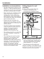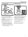
1
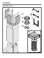
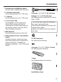
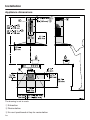
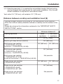
Installation Instructions DA398-6, DA399-6 en - CA Installation, repair and maintenance work should be performed by a Miele authorized service technician in accordance with national and local safety regulations and the provided installation instructions. Installation Before installation Before installing the appliance, read all of the information contained in this chapter and also in the "IMPORTANT SAFETY INSTRUCTIONS" section. Removing the protective film Disassembly If the device ever needs to be disassembled, follow the installation sheet instructions in reverse order. A lever is provided to assist with the removal of the chimney. Unscrew the two mounting screws on the chimney. The housing components are covered by a protective film to prevent them from becoming damaged during transport. Please remove this film before installing the housing components. It can be peeled off easily without any additional tools. Installation Instructions Please refer to the accompanying installation sheet for instructions on how to install the appliance. Slide the supplied lever between the chimney and the extension piece. Pry the chimney out of its attachment. 23 Installation Installation parts 24 Installation a 3 protective installation sheets for use when installing the chimney b 1 exhaust connector for an exhaust duct 6" (150 mm). 8 screws, ³/₁₆" x 2 ³/₈" (5 x 60 mm) c 1 reducer for an exhaust duct 5" (125 mm). 8 plugs, ⁵/₁₆" x 2" (8 x 50 mm) for attaching to the wall (not for use in USA / CDN). d 1 non-return flap for installation in the outlet duct collar of the motor unit (not for recirculation mode). Depending on the device version, the non-return flap is already mounted. e Wall bracket for securing the hood on the wall. f Recirculation kit for recirculation mode contains diverter, aluminum hose and hose clamps (not contained in scope of delivery, available as optional accessory – see "Technical Data"). The screws and plugs are designed for use in solid walls only. Use different fasteners for other wall construction types. Make sure that the wall can support the load. 2 x M 6 locknuts for securing the canopy. 2 screws ¹/₈" x ⁵/₁₆" (3.9 x 7.5 mm) for attaching the chimney. 1 lever for disassembling the chimney. Mo e ntag tallation aje gio nt Ins Mo Montag ntering agem s nt Mo Mo Asennu Installation sheet 25 Installation Appliance dimensions The drawing is not to scale. a Extraction b Recirculation c Air vent positioned at top for recirculation 26 Installation de Mounting area (only d is required for recirculation hoods). Wall and ceiling area for exhaust duct opening and for wall socket installation. Only the wall socket installation is required for recirculation hoods. Vent collar 6" (150 mm), with adapter 5" (125 mm). Distance between cooktop and ventilation hood (S) Provided a larger distance is not given by the manufacturer of the cooktop, follow the minimum safety distances between a cooktop and the bottom of the hood. Please also observe the information contained in the "IMPORTANT SAFETY INSTRUCTIONS" section. Minimum distance S Cooking appliance Miele appliance Non-Miele appliance Electric/Induction cooktop 24" (610 mm) Electric grill, deep fat fryer (electric) 26" (660 mm) Multi-burner gas cooktop ≤ 43,000 BTU/hr (12.6 W), no burner > 15,000 BTU/hr (4.5 kW). 26" (660 mm) 30" (760 mm) Multi-burner gas cooktop ≤ 73,800 BTU/hr (21.6 W), no burner > 16,500 BTU/hr (4.8 kW) 30" (760 mm) Multi-burner gas cooktop > 73,800 BTU/hr (21.6 W), or one of the burners > 16,500 BTU/hr (4.8 kW) Not possible Single-burner gas cooktop ≤ 20,500 BTU/hr (6 kW) 26" (660 mm) 30" (760 mm) Single-burner gas cooktop > 20,500 BTU/hr (6 kW) ≤ 27,600 BTU/hr (8.1 kW) 30" (760 mm) Single-burner gas cooktop > 27,600 BTU/hr (8.1 kW) Not possible 27 Installation Installation recommendations – We also recommend a distance of at least 25 ¹/₂" (650 mm) above electric cooktops to provide more workspace and easier cooking under the hood. Drilling diagram for wall mounting When drilling, please follow the directions contained on the accompanying installation sheet. – When selecting an installation height, always take the user height into consideration. Users should have ample space to work comfortably on the cooktop and reach the ventilation hood controls with ease. – Please note that the greater the distance from the cooktop, the less effective the hood is at drawing in the cooking vapors. – To achieve optimal vapor extraction, make sure that the hood covers the cooktop. The hood should be positioned centrally over the cooktop, not to the side or rear. – The cooktop should be no wider than the hood. Preferably, it should be narrower. – The mounting area must be easily accessible. The ventilation hood should be easy to reach and disassemble in case a service call is necessary. This should be taken into consideration when planning the position of cupboards, shelves, ceilings or decorative elements in the vicinity of the ventilation hood. 28 When installing a custom back wall with pre-drilled holes, please refer to the drilling distances in the drawing above (screws ³/₁₆" (5 mm)). * The dimension for the middle wall bracket is variable. It will depend on the position of the wall vent and the socket. It should be set as low as possible. Installation Plywood backing The majority of the weight of the installed ventilation system will be supported by the lower retaining plate. It must be firmly attached to the stud framing behind the drywall. If studs are not available in the required locations, a plywood backing (min. ½" (13 mm) thick) spanning at least two studs must be installed. Failure to adequately support the weight as stated may result in the ventilation system falling off the wall, causing personal injury and property damage. If plywood backing is not needed, proceed to the included "Installation diagram". To install a plywood backing Make a cutting line 3" (76 mm) above and 3" (76 mm) below the outline of the retaining plate. Find the studs to the left and right of the mounting location by tapping the wall or using a stud finder. Mark a vertical cutting line along the center of each stud. CAUTION: When cutting or drilling into the wall or ceiling, do not damage electrical wiring and other hidden utilities. Remove the drywall between the cutting lines and replace it with plywood of a matching thickness (min. ½" (13 mm) thick). Tape the joints and refinish the wall. Proceed to the enclosed "Installation diagram" to complete the installation. Determine and mark the location of the retaining plate for the canopy as outlined on the "Installation diagram". 29 Exhaust duct WARNING: Danger of toxic fumes. Gas cooking appliances release carbon monoxide that can be harmful or fatal if inhaled. To reduce the risk of fire and to properly exhaust air, the exhaust gases extracted by the hood should be vented outside of the building only. Do not vent exhaust air into spaces within walls or ceilings or in attics, crawl spaces or garages. To reduce the risk of fire, only use metal ductwork. Please read and follow the "IMPORTANT SAFETY INSTRUCTIONS" to reduce the risk of personal injury. Follow all local building codes when installing the hood. Only use smooth pipes or flexible duct hoses made from nonflammable materials for exhaust ductwork. To achieve the greatest possible air extraction with the lowest noise levels, please note the following: – The diameter of the exhaust duct should not be less than 6" (150 mm). – If flat exhaust ducts are used, the cross section should not be smaller than that of the exhaust connector. – The exhaust duct should be as short and straight as possible. – If elbows are needed, make sure they have a large radius. – The exhaust duct itself must not be kinked or compressed. 30 – Make sure that all connections are secure and airtight. Remember that any constriction of the airflow will reduce extraction performance and increase operating noise. If the exhaust duct is to be routed through an outside wall, we recommend installing a telescopic wall vent or a rooftop vent (available as an optional accessory). If the exhaust air is to be conducted into a vent flue, the intake piece must be aligned with the flow direction of the flue. When installing the exhaust duct horizontally, you must slope it away from the source by at least 1 cm per meter (³/₈" per 3 ¹/₄"). This ensures that condensate cannot drain back into the ventilation hood. If the exhaust duct is to be routed through rooms, ceiling space etc., the temperatures in these different areas may differ greatly, which means that the problem of condensation will need to be addressed. The exhaust duct will need to be insulated. Exhaust duct Condensate trap Reducing Collar (optional accessory) In addition to insulating the exhaust duct, we recommend installing a condensate trap to collect and evaporate any condensate which might accumulate. Condensate traps are available for exhaust ducts with a diameter of 5" (125 mm) or 6" (150 mm). When installing a condensate trap, make sure that it is positioned vertically and, if possible, directly above the hood outlet duct collar. The arrow on the housing indicates the direction of airflow. If you would like to reduce the environmental impact of your ventilation system by limiting the CFM output the Reducing Collar can be installed. It reduces the air flow to less than 400 CFM. Check local building codes for max. CFM requirements. Push the Reducing Collar on the exhaust port of the fan. Push the exhaust hose over it. Fix both with a hose clamp. 31 Electrical connection WARNING: TO REDUCE THE RISK OF FIRE, ELECTRIC SHOCK, OR INJURY TO PERSONS, OBSERVE THE FOLLOWING: All electrical work should be performed by a qualified electrician in strict accordance with national regulations (for USA: ANSI-NFPA 70) and local safety regulations. Installation, repairs and other work by unqualified persons could be dangerous. Ensure that power to the appliance is OFF while installation or repair work is performed. Verify that the voltage, load and circuit rating information found on the data plate (located behind the baffle filters), match the household electrical supply before installing the hood. Use only with ventilation hood cordconnection kits that have been investigated and found acceptable for use with this model hood. If there is any question concerning the electrical connection of this appliance to your power supply, please consult a licensed electrician or call Miele’s Technical Service Department. WARNING: THIS APPLIANCE MUST BE GROUNDED The hood comes equipped with a power cord with a NEMA 5-15 molded plug for connection to a 120 VAC, 60 Hz, 15 A power outlet. 32 Grounding Instructions WARNING - Improper grounding can result in a risk of electric shock. This appliance must be grounded. In the event of an electrical short circuit, grounding reduces the risk of electric shock by providing a path of least resistance. This appliance is equipped with a cord having a grounding wire with a grounding plug. If there is any doubt, have the electrical system of the house checked by a qualified electrician. Do not use an extension cord. If the power supply cord is too short, have a qualified electrician install an outlet near the appliance. The plug must be plugged into an outlet that is properly installed and grounded. WARNING - Grounding instructions (Canada) The grounding-type attachment plug shall be connected to a groundingtype receptacle installed in accordance with CSA C22.1-12, Canadian Electrical Code, Part I. Service and warranty For faults that you cannot resolve on your own, please contact your Miele dealer or Miele Technical Service. The telephone number for the Technical Service Department is listed at the back of these instructions. When contacting Miele, please state the model and serial number of your ventilation hood. These can be found on the data plate. Location of the data plate The data plate is visible once you have removed the grease filters. Warranty For further information, please refer to your warranty booklet. 33 Technical data Fan motor Cooktop lighting Total connected load Voltage, Frequency Fuse rating Power cord length 350 W 2 x 50 W 450 W 120 V AC, 60 Hz 15 A 2.5 ft (0.75 m) Weight DA 398-6 55.3 lbs (25.1 kg) DA 399-6 57.2 lbs (26 kg) Optional accessories for recirculation mode: Recirculation kit DUW 20 and OdorFree Charcoal Filter DKF 12 34 Please have the model and serial number of your appliance available before contacting Technical Service. U.S.A. Canada Miele, Inc. Importer Miele Limited National Headquarters 9 Independence Way Princeton, NJ 08540 Phone: 800-843-7231 609-419-9898 609-419-4298 Fax: www.mieleusa.com Technical Service & Support Nationwide Phone: 800-999-1360 888-586-8056 Fax: [email protected] Headquarters and Miele Centre 161 Four Valley Drive Vaughan, ON L4K 4V8 www.miele.ca Customer Care Centre Phone: 800-565-6435 905-532-2272 [email protected] Germany Manufacturer Miele & Cie. KG Carl-Miele-Straße 29 33332 Gütersloh 35 DA 398-6 DA 399-6 en-US M.-Nr. 09 968 240 / 02