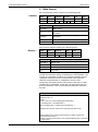
1
LAB Documentation Communication Protocol Operating instructions for SIMDOS RC Plus Before operating the pump and the accessories, please read the operating instructions on the web site (www.knf.com/downloads) and pay attention to the safety precautions! KNF FLODOS AG Wassermatte 2 6210 Sursee, Schweiz Tel +41 (0)41 925 00 25 Fax +41 (0)41 925 00 35 www.knf.com Communication protocol Index 1 Index 1 Index ................................................................................... 3 2 General ............................................................................... 4 3 Initial start-up .................................................................... 5 4 Universal commands ....................................................... 6 5 Interface parameters ........................................................ 6 6 Data format ........................................................................ 7 7 Protocol answer ................................................................ 8 8 Operation modes and their limitations ......................... 9 9 Commands .......................................................................10 9.1 Troubleshooting ..............................................................43 10 11 KNF Flodos CP_SIMDOS02_EN_01_166851 Function list ............................................................................. 10 10.1 Communication problems ................................................. 43 10.2 Displaying of error messages .......................................... 43 Command Index ...............................................................44 3 General Communication protocol 2 General The SIMDOS RC Plus pumps can be controlled by using the standard RS232 serial interface (COM1, COM2, … ). The RS232 serial interface allows one pump to be controlled by a PC based software tool. Any of the commands listed in this document can be carried out as single commands for pump control or verification purpose. This may be of help for customers, who want to develop their own pump control tool. If your PC does not provide an RS232 serial interface, then use an USB to RS 232 Adaptor! The communication protocol is only available for the following products: 4 Name KNF Typ SIMDOS 10 XX RC Plus FEM1.10 XX.18 RCP SIMDOS 02 XX RC Plus FEM1.02 XX.18 RCP KNF Flodos CP_SIMDOS02_EN_01_166851 Communication protocol Initial start-up 3 Initial start-up WARNING Danger of automatic start-up The pump starts up by itself and without warning. Do not transmit a start command until the system has been tested and is ready for operation Mark remote-controlled pumps Before start-up, check that hoses and equipment are leak-tight and working properly Do not operate the pump with hazardous media 1. switch on the pump 2. Remove protective caps from RC connector plug. 3. Connect the serial cable (D-Sub cable) to the pump. 4. Connect serial cable for remote control (D-Sub cable) to a suitable signal source. Master D-Sub 9 connector Pumpside Fig. 1: KNF Flodos serial cable pin assignment 5. If your PC is not equipped with an RS 232 Interface, an additional adaptor is needed. 6. Make sure that the cables are connected 7. Check connection with: Transmit Receive: Name STX Address Cmd str ETX LRC Example 2 00 ?SI 3 36 Name Cmd str ETX LRC 3 1 2 STX Example 2 8. If the address has to be changed, make sure, that the message is send with the right address. KNF Flodos CP_SIMDOS02_EN_01_166851 5 Universal commands Communication protocol 4 Universal commands The address number 99 has a special function. Commands, which don’t require an answer, can be sent to address 99. The command will be carried out by all pumps. This enables synchronized functions such as the start of all pumps at once. 5 Interface parameters The pump is permanently set to the following values: Name Value Baud Rate 9600 Baud Data Bits 8 Parity No Stop Bit 1 Handshake: There’s no monitoring. The user is responsible that the pump is not overloaded. Timing: The typical reaction time of the pump is 2 ms. If the answer takes longer than 100 ms, there is either a problem with the communication or the pump is still busy with a time consuming function e.g. new pump initializations. 6 KNF Flodos CP_SIMDOS02_EN_01_166851 Communication protocol Data format 6 Data format Each transmission packet consists of the following bytes: Transmit Name Size Example STX Address 1 Byte 2 Cmd str 2 Bytes 0 ETX 3 – 10 Bytes 0 ? S LRC 1 Byte 1 Byte 3 36 I STX (02h) Start of Text Address Pump address ‘00’ – ‘99’ ASCII, can be set on the pump command string Order of ASCII symbol according to command (cmd str) description ETX (03h) End of Text LRC Checksum Each receiver packet consists of the following bytes: Receive : Name Size STX 1 Byte Cmd str ETX 1 – 9 Bytes 0 0 LRC 1 Byte 1 Byte 3 36 Example 2 STX (02h) Start of Text Answer All data are in ASCII format ETX (03h) End of Text LRC Checksum The checksum is the last byte in a command string. All bytes (except the checksum (LRC)) are linked by an XOR operation. The receiver of a message compares the received checksum with the calculated checksum from the received data; if the values are identical, the transmission is considered to be error-free. Instead of a calculated LRC the ASCII Code of the letter ‘U’ (decimal 85) can be transmitted. In this case, the pump does not compute the checksum of the received data and takes the checksum as valid. Pseudo code for LRC computation: LRC = 0 CharacterIndex = 0 Repeat LRC = LRC xor CommandString[CharacterIndex] CharakterIndex = CharakterIndex + 1 Until CharakterIndex = LENGTH(CommandString) - 1 …. Compare LRC with the received LRC-byte (first byte after ETX) …. Where LENGTH() is a function that returns the number of bytes that CommandString contains. Assuming that the first character in the CommandString array is accessed by index value 0. KNF Flodos CP_SIMDOS02_EN_01_166851 7 Protocol answer Communication protocol 7 Protocol answer First, the pump checks the formal correctness of any received command. The Format as described in this document and LRC have to be correct. The address in the received packet has to be equal to the pump’s address. After the acceptance of the command, it will be executed. If the command has been executed, the processing of the command is either positively or negatively acknowledged. Positive acknowledge ACK (deciaml 6) means a successful processing of the command. Negative acknowledge NACK (decimal 21) means either a formal error while receiving the command or a failure to process the command. No details are available. If the command to the pump demands a reply (i.e. status information or the value of a parameter), a leading ACK indicates the successful processing of the command. Afterwards the actual content of the answer is transmitted. In case of an invalid command a single NACK is returned. Example: An answer for a formally correct command that demanded a reply, like: ?SI (Pump Address) : Transmit Name STX Example Receive Address 2 0 Meaning Ack Example 0 STX #6 Cmd str ? ETX S I Data 2 0 3 ETX 0 3 LRC 36 LRC 1 The Pump address is 00. #6 ACK STX (02h) Start of text Data block ASCII code according to the command list ETX (03h) End of text LRC Checksum Overview of protocol response of the pump Situation of received packet Response Remarks Correct LRC, Address match, formally correct content and command successfully executed ACK Formally correct means a valid command mnemonic and the right number of digits for the parameter Formally incorrect content NACK Invalid mnemonic or parameter field contains an incorrect number of digits Parameter out of range NACK Any set parameter is range checked Command not executed NACK An internal state prevents the command from execution Wrong LRC No answer ‘U’ is generally accepted as a valid LRC for any received packet Wrong address No answer Address = 99 No answer 8 KNF Flodos CP_SIMDOS02_EN_01_166851 Communication protocol Operation modes and their limitations NOTICE It is not allowed that two pumps can send their answers simultaneously The protocol answer can be deactivated (see command SPn). In this case no ACK or NACK sign is returned. The reply for commands that asked for information is always returned. 8 Operation modes and their limitations MS==0: Run Mode DT: unused DV: unused RV is forced to be within the interval [RVmin, RVmax] by the firmware. MS==1: Metering by set volume and time DT: is forced to be within the interval [DTmin, DTmax] by the firmware. 𝐷𝑇𝑚𝑖𝑛 = 𝐷𝑇𝑚𝑎𝑥 = 𝐷𝑉 𝑅𝑉𝑚𝑎𝑥 𝐷𝑉 𝑅𝑉𝑚𝑖𝑛 DV: set by the user (check limits [DVmin, DVmax]) RV is forced to be within the interval [RVmin, RVmax] by the firmware. MS==2: Metering by set flow rate and time DT: DV: set by the user calculated by firmware 𝐷𝑉 = 𝐷𝑇 𝑅𝑉 RV is forced to be within the interval [RVmin, RVmax] by the firmware. Legend DT: Dispense time [s] RV: Flow rate [µl/min] DV: Metering volume [µl] SIMDOS 02 RVmin 0.03ml/min RVmax 20ml/min DVmin 0.03ml DVmax 1000l SIMDOS 10 KNF Flodos CP_SIMDOS02_EN_01_166851 RVmin 0.1ml/min RVmax 100ml/min DVmin 0.1ml DVmax 1000l 9 Commands Communication protocol 9 Commands 9.1 10 Function list 9.1.1 Mode select: Run-mode / Dispense-mode .................. 11 9.1.2 Start, Stop, Prime/Drain ................................................. 12 9.1.3 Run mode flow rate µl/min............................................. 13 9.1.4 Dispense mode dispense volume µl ............................ 15 9.1.5 Dispense mode time for dispensing a volume .......... 16 9.1.6 Dispense mode: number of volumes........................... 18 9.1.7 Dispense mode: Break time between volumes.......... 19 9.1.8 Actual run or dispense time counter. .......................... 20 9.1.9 Actual run or dispense volume counter µl ................. 21 9.1.10 Analog control signal type selection ........................... 22 9.1.11 Analog Range Selection ................................................ 23 9.1.12 Digital input 1 function ................................................... 24 9.1.13 Digital input 2 function ................................................... 25 9.1.14 Open collector output function .................................... 27 9.1.15 Language select .............................................................. 28 9.1.16 Customer level measured calibration volume ........... 29 9.1.17 Customer level calibration factor % ............................ 30 9.1.18 Characteristic pump profile selection ......................... 31 9.1.19 LCD display contrast ...................................................... 32 9.1.20 Auto-start after power on ............................................... 33 9.1.21 Pump model and firmware version .............................. 34 9.1.22 Communication check function ................................... 35 9.1.23 Protocol answer setting ................................................. 36 9.1.24 Initialize the pump (new start) ....................................... 37 9.1.25 Pump reset to factory settings ..................................... 38 9.1.26 Pump status request ...................................................... 39 9.1.27 Pump address nn ............................................................ 41 9.1.28 Maintenance position ..................................................... 42 KNF Flodos CP_SIMDOS02_EN_01_166851 Communication protocol Commands 9.1.1 Summary: Mode select: Run-mode / Dispense-mode Selects the active operating mode of the pump. Set command Command string: MSn Parameter name: MS Parameter value: n (1 digit, right adjusted) MS1 ⇒ Dispense Mode, ml and Time is active Example: n Function 0 Run Mode is active (Factory preset)(Auto-start preset) 1 Dispense Mode ml and time is active 2 Dispense Mode ml/min and time is active Read command Command string: ?MS Answer: n (1 digit, right adjusted) Example Transmit ?MS Receive 1 n Meaning 0 Run Mode is active 1 Dispense Mode ml and time is active 2 Dispense Mode ml/min and time is active Display on Pump User Interface: n Display 0 Volume: unit = ml/min Time: - - min - - sec 1 Volume: unit = ml Time: 99 min 99 sec 2 Volume: unit = ml/min Time: 99 min 99 sec Power OFF behavior: State of MS is saved Auto-start Power OFF behavior: State of MS is saved Remarks: KNF Flodos CP_SIMDOS02_EN_01_166851 Take notice of the limits! See chapter 8. 11 Commands Communication protocol 9.1.2 Summary: Start, Stop, Prime/Drain To initiate primary pump function. Start pumping, stop pumping, start Prime/Drain cycle. Set command Parameter name: KY Parameter value: n Command string: KYn Example: (1 digit, right adjusted) KY2 ⇒ Priming the pump n Function 0 Stop (Factory preset) 1 Start (Auto-start preset) 2 Prime/Drain (1 stroke) 3 Pause Read Command: Command string: No parameter read function Display on Pump User Interface: n Display 0 Volume counter stops and the STOP indicator is active 1 Volume counter either resets to 0 or keeps its value and starts counting corresponding to the previous state of pump (either 0 (STOP) or 3 (PAUSE)) 2 Volume counter resets to 0 and finally displays the dispensed volume of the prime stroke 3 Volume counter xxx stops, is blinking and the PAUSE indicator is active Power OFF behavior: State of KY reset to factory preset (Always Stop when power ON). Auto-start Power OFF behavior: State of KY reset to factory preset (Always Stop when power ON). Remarks: 12 See AS (Section 9.1.20) for more information on autostart KNF Flodos CP_SIMDOS02_EN_01_166851 Communication protocol Commands 9.1.3 Summary: Run mode flow rate µl/min. Sets the set value for the flow rate in Run mode. The unit is µl/min. Set command Command String RVnnnnnnnn Command name: RV Parameter value: nnnnnnnn Example: (8 digits, right adjusted) RV00020000 ⇒ 20’000 µl/min SIMDOS10 nnnnnnnn Function 0...99’999’999 Set value for the flow rate [µl/min] in Run mode 00’100’000 FEM 1.10 Maximum accepted value (NACK if higher) 00’001’000 FEM 1.10 Minimum accepted value (NACK if lower) 00’010’000 Factory preset SIMDOS02 nnnnnnnn Function 0...99’999’999 Set value for the flow rate [µl/min] in Run mode 00'020'000 FEM 1.02 .18 Maximum accepted value (NACK if higher) 00'000'030 FEM 1.02 .18 Minimum accepted value (NACK if lower) 00’10’000 Factory preset Read Command Command String Answer: Example: KNF Flodos CP_SIMDOS02_EN_01_166851 ?RV nnnnnnnn (8 digits, right adjusted) Transmit ?RV Receive 00020000 nnnnnnnn Meaning 0…99999999 Current set value for flow rate in µl/min 13 Commands Communication protocol Display on Pump User Interface: SIMDOS10 nnnnnnnn Display 1.0 … 100.0 Volume nnn.n ml/min (when in Run mode MS = 0) SIMDOS02 nnnnnnnn Display 0.03 … 20.00 Volume nn.nn ml/min (when in Run mode MS = 0) Power OFF behavior: Value of RV is saved Auto-start Power OFF behavior: Value of RV is saved Remarks: 14 Take notice of the limits! See chapter 8. KNF Flodos CP_SIMDOS02_EN_01_166851 Communication protocol Commands 9.1.4 Summary: Dispense mode dispense volume µl Sets the set value for the dispense volume in Dispense-mode. The unit is µl. Set command Command string DVnnnnnnnn Command name: DV Parameter value: nnnnnnnn Example: (8 digits, right adjusted) DV00020000 ⇒ 20’000 µl SIMDOS10 nnnnnnnn Function 0...99’999’999 Set value for the dispense volume in Dispense mode [µl] 00’999’999 Maximum accepted value (NACK if higher) 00’001’000 Minimum accepted value (NACK if lower) 00’010’000 Factory preset, Auto-start preset SIMDOS02 nnnnnnnn Function 0...99’999’999 Set value for the dispense volume in Dispense mode 00’999’999 Maximum accepted value (NACK if higher) 00'000'030 Minimum accepted value (NACK if lower) 00’10’000 Factory preset, Auto-start preset Read command Command string: Answer: Example ?DV nnnnnnnn (8 digits, right adjusted) Transmit ?DV Receive 00020000 ⇒ 20’000 µl nnnnnnnn Meaning min…99999999 Current set value for dispense volume in µl Display on Pump User Interface: nnnnnnnn Massage min … 999.9 Volume nnn.n ml (when in Dispense mode MS = 1) Power OFF behavior: Value of DV is saved Auto-start Power OFF behavior: Value of DV is saved Remarks: KNF Flodos CP_SIMDOS02_EN_01_166851 Take notice of the limits! See chapter 8. 15 Commands Communication protocol 9.1.5 Summary: Dispense mode time for dispensing a volume Sets the set value for the time to dispense a volume in Dispense mode. Set command Command string: DThhmmssss Parameter name: DT Parameter value: hhmmssss Example: (8 digits, [hh:mm:ss.ss] “h”: hour, “m”: minute, “s”:seconds, “.ss”: 1/100 seconds) DT00010000 ⇒ 1 min hhmmssss Function 99‘99’99’99 Set value for the time to dispense a volume in Dispense mode 99’59’59’99 Maximum accepted value (NACK if higher) 00’00’01’00 Minimum accepted value (NACK if lower) 00’00’10’00 Factory preset, Auto-start preset (10 seconds) Read command Command string: Answer: Example: ?DT hhmmssss (8 digits, right adjusted) Transmit ?DT Receive 00010000 ⇒ 1 min hhmmssss Meaning 0…99999999 “h”: hour, “m”: minute, “s”:seconds, “.ss”: 1/100 seconds Display on Pump User Interface: nn:nn Display mm:ss 00:01 - 59:59 Time: mm [min.] ss [sec.] (when in Dispense mode MS = 1 or 2) hh:mm 01:00 - 99:59 Time: hh [h.] mm [min.] (when in Dispense mode MS = 1 or 2) off --:-- Time: - - min - - sec (when in Run mode MS = 0) User Interface behavior: • If time is dialed from “0” to a time value, then: MS = 1 or 2, DV = RV • If time is dialed to “0”, then: MS = 0, RV = DV, display time “off” Power OFF behavior: Value of DT is saved Auto-start Power OFF behavior: Value of DT is saved 16 KNF Flodos CP_SIMDOS02_EN_01_166851 Communication protocol Commands Remarks: Take notice of the limits! See chapter 8. NOTICE The pump will only accept this dispense time, as long as it is between the pump internal min. and max. time for dispensing a selected basic dispense volume, otherwise the pump will set the internal min. or max. time. A simple read back helps to check the actual dispense time. Time resolution is 1.00s. KNF Flodos CP_SIMDOS02_EN_01_166851 17 Commands Communication protocol 9.1.6 Summary: Dispense mode: number of volumes The number of cycles, that the given volume shall be dispensed, is defined Set command Command string: DNnnnnn Command name: DN Parameter value: nnnnn Example (5 digits, right adjusted) DN00050 ⇒ 50 cycles nnnnn Function 0 Function off 1 Cyclic dispensing is deactivated 2...999 nnnnn represents the number of dispensed volumes 1000 Infinite number of repetitions Read command Command string: Answer: Example: ?DN nnnnn (5 digits, right adjusted) Transmit ?DN Receive 00050 ⇒ 50 cycles nnnnn Meaning 0 Function off 1 Cyclic dispensing is deactivated 2...999 Currently configured number of dispense volumes 1000 Dispense volume is infinitely repeated Display on Pump User Interface: nnnnn Display 0 Function off 1 Cyclic dispensing is deactivated (no indication) 2...999 Counter of dispensed volumes / Number of volumes 1000 The text string "INF" Power OFF behavior: Value of DN is saved Auto-start Power OFF behavior: Value of DN is saved Remarks: 18 1/100 s are rounded to seconds as this is the minimum resolution of time. KNF Flodos CP_SIMDOS02_EN_01_166851 Communication protocol Commands 9.1.7 Summary: Dispense mode: Break time between volumes Break time between two programmed dispense cycles Set command Command string: DBnnnnn Parameter name: DB Parameter value: nnnnn Example: (5 digits, right adjusted) DB00010 ⇒ 10 seconds break time nnnnn Function 1...5999 Break time in seconds Read Command Command string: Answer: Example: ?DB nnnnn (5 digits, right adjusted) Transmit ?DB Receive 00010 ⇒ 10 seconds break time nnnnn Meaning 1...5999 Break time in seconds Display on Pump User Interface: nnnnn Display 1...5999 Break time in seconds, is counting backwards when active Power OFF behavior: Value of DB is saved Auto-start Power OFF behavior: Value of DB is saved Remarks: KNF Flodos CP_SIMDOS02_EN_01_166851 -- 19 Commands Communication protocol 9.1.8 Summary: Actual run or dispense time counter. Time counter of the Dispense mode (and Run mode). Counter resets to 0 and starts at dispense start or run start Set command Command string: No command string Parameter name: -- Parameter value: -- Example: -- Read command Command string: Answer: Example: ?TT hhmmssss 5 digits, right adjusted [hh:mm:ss.ss] “h”: hour, “m”: minute, “s”:seconds, “.ss”: 1/100 seconds Transmit ?TT Receive 00010000 ⇒ 1 minute hhmmssss Meaning 0…99999999 “h”: hour, “m”: minute, “s”:seconds, “.ss”: 1/100 seconds 00000000 Dispense is not started / Run is not started Display on Pump User Interface: No Display Power OFF behavior: Value of TT is not saved Auto-start Power OFF behavior: Value of TT is not saved Remarks: 20 -- KNF Flodos CP_SIMDOS02_EN_01_166851 Communication protocol Commands 9.1.9 Summary: Actual run or dispense volume counter µl Volume counter of the Dispense mode (and Run mode). Counter resets to 0 and starts at dispense start or run start Set command Command string: No command string Parameter name: -- Parameter value: -- Example: -- Read command Command string: Answer: Example: ?TV nnnnnnnnn (9 digits, right adjusted) Transmit ?TV Receive 000010000 ⇒ 10 ml nnnnnnnnn Meaning 0…999‘999‘999 Dispensed volume in µl Display on Pump User Interface: n Display 0…999999.9 Dispensed volume since last pump start in ml > 999999 If Upper limit of TV is reached the counter stops Power OFF behavior: Value of TV is not saved Auto-start Power OFF behavior: Value of TV is not saved Remarks: Since the pump only dispenses during pressure strokes, the dispense counter needs calibration. The counter is based on the calibrated pump stroke volume which is summed up by incremental steps. Take note of the upper limit. If the dispensed volume is larger than the upper limit of TV, the volume counter displays the difference to 1000 l and the display shows “> 1000 l” KNF Flodos CP_SIMDOS02_EN_01_166851 21 Commands Communication protocol 9.1.10 Analog control signal type selection Summary: Selects the analog signal type Set command Command string: RAn Parameter name: RA Parameter value: n (1 digit, right adjusted) RA2 ⇒ Analog signal 4…20mA Example: n Function 0 Analog signal 0…10V (Factory default) 1 Analog signal 0…20mA 2 Analog signal 4…20mA 3 Analog signal 0..5V 9 Analog signal OFF Read command Command string: Answer: Example: ?RA n (1 digit, right adjusted) Transmit ?RA Receive 2⇒ Analog signal 4…20mA n Meaning 0 Analog signal 0…10V (Factory default) 1 Analog signal 0…20mA 2 Analog signal 4…20mA 3 Analog signal 0..5V 9 Analog signal OFF Display on Pump User Interface: Display indicates only if analog input is active or not. User Interface behavior: When analog signal is changed from “off” to another value, then: RA changes accordingly. Power OFF behavior: Value of RA is saved Auto-start Power OFF behavior: Value of RA is saved Remarks: -- NOTICE If pump is not in “run mode” any value except “analogue off” is not accepted. (NACK will be returned) 22 KNF Flodos CP_SIMDOS02_EN_01_166851 Communication protocol Commands 9.1.11 Flow rate range selection for analog input Summary: Sets one of the three flow rate ranges Set command Command string: RBn Parameter name: RB Parameter value: n (1 digits, right adjusted) RB2 ⇒ flow rate range is set to 0.15 – 15%. Example: n flow rate range 0 1 – 100% of full scale 1 0.3 – 30% of full scale 2 0.15 – 15% of full scale (Factory default) Read command Command string: Answer: Example: ? RB n (1 digits, right adjusted) Transmit ?RB Receive RB2 ⇒ flow rate range is set to 0.15 – 15%. n flow rate range 0 1 – 100% of full scale 1 0.3 – 30% of full scale 2 0.15 – 15% of full scale (Factory default) Display on Pump User Interface: No special indications on the main display. It’s indicated in the range setting menu (System=>Range) • User Interface behavior: The displayed fow rate (main display) will change according to the selected flow rate range. When the flow rate ranges is changed to another value, then: RB changes accordingly. Power OFF behavior: Value of RB is saved Auto-start Power OFF behavior: Value of RB is saved Remarks: The analog input must be activated: • 0–5V • 0 – 10 V • 0 – 20 mA • 4-20 mA otherwise the pump ignores any correct applied analog signal and the pump is only controlled by the user interface. KNF Flodos CP_SIMDOS02_EN_01_166851 23 Commands Communication protocol 9.1.12 Digital input 1 function Summary: Selects the function of the digital input 1. Set command Command string: L1nn Parameter name: L1 Parameter value: nn (2 digits, right adjusted) L101 ⇒ Digital input 1, is configured for a level controlled Start/stop signal Example: nn Function 00 Signal: Off (Factory default) 01 level controlled: Start/stop 06 edge controlled: Start/stop Read command Command string: Answer: Example: ?L1 nn (2 digits, right adjusted) Transmit ?L1 Receive L101 ⇒ Digital input 1, is configured for level controlled Start/stop signals nn Meaning 00 Signal: Off (Factory default) 01 level controlled: Start/stop 06 edge controlled: Start/stop Display on Pump User Interface: Display indicates only if digital input is active or not (high and low). User Interface behavior: IF L1 is set to 01 or 06, the selected option is not accessible for L2. Power OFF behavior: Value of L1 is saved Auto-start Power OFF behavior: Value of L1 is saved Remarks: 24 L1 and L2 cannot be set to 01 or 06 at the same time. Protocol answer is NACK in case of conflicting settings. KNF Flodos CP_SIMDOS02_EN_01_166851 Communication protocol Commands 9.1.13 Digital input 2 function Summary: Selects the function of the digital input 2. Set command Command string: L2nn Parameter name: L2 Parameter value: nn (2 digits, right adjusted) L201 ⇒ Digital input 2, is configured for level controlled Start/stop signals Example: Logic level nn Function 00 Signal 2: Off (Factory default) 01 level controlled: Start/stop signal 06 edge controlled: Start/stop signal 08 Pump Error reset & Pump Stop on signal edge. 09 Prime/Drain on signal level and error reset on signal edge 10 Error reset on signal edge and Prime/Drain after 1 second on signal level L2 = 08 active [1] not active [0] Error reset t L2 = 09 Prime/Drain active [1] not active [0] Error reset L2 = 10 t Prime/Drain active [1] not active [0] 1s t Error reset KNF Flodos CP_SIMDOS02_EN_01_166851 25 Commands Communication protocol Read command Command string: Answer: Example: ?L2 nn (2 digits, right adjusted) Transmit ?L2 Receive L201 ⇒ Digital input 2, configured for level controlled start/stop signals nn Meaning 00 Signal 2: Off (Factory default) 01 level controlled: Start/stop 06 edge controlled: Start/stop 08 Pump Error reset & Pump Stop on signal edge. 09 Prime/Drain on signal level and error reset on signal edge 10 Error reset on signal edge and Prime/Drain after 1 second on signal level Display on Pump User Interface: Display indicates only if digital input is active or not (high and low). User Interface behavior: IF L2 is set to 01 or 06, the selected option is not accessible for L1. Power OFF behavior: Configuration of L2 is saved Auto-start Power OFF behavior: Configuration of L2 is saved Remarks: 26 L1 and L2 cannot be set to 01 or 06 at the same time. Protocol answer is NACK in case of conflicting settings. KNF Flodos CP_SIMDOS02_EN_01_166851 Communication protocol Commands 9.1.14 Open collector output function Summary: Defines the function of the open collector output (low active) Set command Command string: RSn Parameter name: RS Parameter value: n (1 digit, right adjusted) RS1 ⇒ Output on active level, when motor is running Example: n Function 0 active signal level when Alarm on Error (Factory default) 1 active signal level when Motor is running 2 active signal level when Volume finish 3 active signal pulse: 4 active signal pulse: 1 pulse per 20µl 1 pulse per 100µl every 1/10 revolution (10 pulses per revolution) SIMDOS 02 SIMDOS 10 Read command Command string: Answer: Example: ?RS n (1 digit, right adjusted) Transmit ?RS Receive RS1 ⇒ Output on active level, when motor is running n Meaning 0 active signal level when Alarm on Error (Factory default) 1 active signal level when Motor is running 2 active signal level when Volume finish 3 active signal pulse: every 1/10 revolution (10 pulses per revolution) 4 active signal pulse: 1 pulse per 20µl SIMDOS 02 1 pulse per 100µl SIMDOS 10 Display on Pump User Interface: Display does not indicate any output signals. User Interface behavior: IF L1 is set to 01 or 06, the selected option is not accessible for L2. Power OFF behavior: Value of RS is saved Auto-start Power OFF behavior: Value of RS is saved Remarks: KNF Flodos CP_SIMDOS02_EN_01_166851 -- 27 Commands Communication protocol 9.1.15 Language select Summary: Selects the language of the user interface Set command Command string: LSn Parameter name: LS Parameter value: n (1 digit, right adjusted) LS1 ⇒ German Example: n Function 0 English 1 German 2 French 3 Spanish 4 Italian 5 Chinese 6 Japanese Read command Command string: Answer: Example: ?LS n (1 digit, right adjusted) Transmit ?LS Receive LS1 ⇒ German n Meaning 0…6 User interface language according to parameter value Display on Pump User Interface: n Display 0…6 User interface language according to parameter value Power OFF behavior: Value of LS is saved Auto-start Power OFF behavior: Value of LS is saved Remarks: 28 -- KNF Flodos CP_SIMDOS02_EN_01_166851 Communication protocol Commands 9.1.16 Customer level measured calibration volume Summary: Customer level calibration based on Run mode flow rate or Dispense mode volume Set command Command string: CFnnnnnnnn Parameter name: CF Parameter value: nnnnnnnn (8 digits, right adjusted) CF 00000100 ⇒ 100 µl or 100 µl/min, it depends on the mode of operation Example: n Function 0...99999999 Customer measured flow rate [µl/min] or dispense volume in [µl] Read command Command string: No parameter read function Answer: - Example: Display on Pump User Interface: n Display 0…9999 Measured value nnnn in ml (when in Dispense mode MS=1) 0…9999 Measured value nnnn in ml/min (when in Run mode MS=0) Power OFF behavior: Value of CF is not saved Auto-start Power OFF behavior: Value of CFis not saved Remarks: The parameter CF is a user input value only. Setting CF initiates the computation of the calibration parameter CH. See definition of CH. NOTICE CH is computed based on CF (see section 9.1.17). If the value of CF violates - after computation - the range of CH, CF is not accepted and a NACK sign is returned. KNF Flodos CP_SIMDOS02_EN_01_166851 29 Commands Communication protocol 9.1.17 Customer level calibration factor % Summary: Customer level calibration factor for pump stroke volume Set command Command string: CHnnnnn Parameter name: CH Parameter value: nnnnn (5 digit, right adjusted) CH08000 ⇒ Minimum accepted value 80%, the pump is calibrated to the lowest range nnn.nn Function Example: 0...999.99 Percentage of the factory calibrated pump stroke volume 080.00 Minimum accepted value 80% (NACK if lower) 120.00 Maximum accepted value 120% (NACK if higher) 100.00 100% (Factory default) Read command Command string: ?CH Answer: nnnnnn (5 digits, right adjusted) Example: Transmit ?CH Receive CH08000 ⇒ Pump is calibrated to 80% nnn.nn Message 0 …999.99 Pump stroke volume correction in % by user calibration Display on Pump User Interface: nnn.nn Message 0...999 Calibration “nnn” % Power OFF behavior: Value of CH is saved Auto-start Power OFF behavior: Value of CH is saved Remarks: Setting the parameter CF initiates the computation of the calibration parameter CH. pseudo code CHnew = CHold *RVset / CF or CHnew = CHold *DVset / CF CHnew Relative customer level calibration (new) CHold Relative customer level calibration (original) RVset/ DVset Set flow rate or set dispense volume CF Measured flow rate or volume (it depends on the mode of operation) NOTICE If the Limit for CH is exceeded a NACK sign is returned and the calibration is not accepted 30 KNF Flodos CP_SIMDOS02_EN_01_166851 Communication protocol Commands 9.1.18 Characteristic pump profile selection Summary: Selects the active pump profile Set command Command string: CCn Parameter name: CC Parameter value: n (1 digit, right adjusted) CC1 ⇒ Profile for volatile fluids is active Example: n Function 0 Standard profile is active 1 Profile for volatile fluids is active 2 Profile for viscous fluids is active 3 Profile for high viscous fluids is active 4 Reserved Read command Command string: Answer: Example: ?CC n (1 digit, right adjusted) Transmit ?CC Receive CC1 ⇒ Profile for volatile fluids is active n Meaning 0 Standard profile is active 1 Profile for volatile fluids is active 2 Profile for viscous fluids is active 3 Profile for high viscous fluids is active 4 Reserved Display on Pump User Interface: n Display 0 Agent “Standard” 1 Agent “Degassing” 2 Agent "Visc100cSt” 3 Agent “Visc500cSt” 4 Reserved Power OFF behavior: Value of CC is saved Auto-start Power OFF behavior: Value of CC is saved Remarks: KNF Flodos CP_SIMDOS02_EN_01_166851 -- 31 Commands Communication protocol 9.1.19 LCD display contrast Summary: Sets the contrast level of the LCD display. Set command Command string: LCnnn Parameter name: LC Parameter value: nnn (3 digits, right adjusted) LC060 ⇒ LCD Contrast 60% n Function 000 ... 100 LCD display contrast setting 100 Maximum accepted value (NACK if higher) 000 Minimum accepted value (NACK if lower) 040 (Factory default) Example: Read command Command string: ?LC Answer: nnn (3 digits, right adjusted) Transmit ?LC Receive LC040 ⇒ LCD Contrast 40% (default setting) nnn Meaning 000…100 LCD display contrast setting Example: Display on Pump User Interface: nnn Display 000…100 Contrast “nnn” Power OFF behavior: Value of LC is saved Auto-start Power OFF behavior: Value of LC is saved Remarks: 32 Take notice of the limits! KNF Flodos CP_SIMDOS02_EN_01_166851 Communication protocol Commands 9.1.20 Auto-start after power on Summary: Settings of automatic start after power off/switch off. With active Auto-start the pump will start automatically if one of the following actions takes place: • The power plug is attached to the pump • The pump is switched on NOTICE If any input control signal is configured the pump will stay in pause state until a start trigger is given. Set command Command string: SAn Parameter name: SA Parameter value: n (1 digit, right adjusted) SA1 ⇒ activate Auto-start Example: n Function 0 Auto-start inactive (Factory default) 1 Auto-start active Read command Command string: Answer: Example: ?SA n (1 digit, right adjusted) Transmit ?SA Receive SA1 ⇒ Auto-start is active n Meaning 0 Auto-start is inactive 1 Auto-start is active Display on Pump User Interface: n Display 0 No display 1 "AS" is displayed above unit indicator Power OFF behavior: Value of SA is saved Auto-start Power OFF behavior: Value of SA is saved Remarks: KNF Flodos CP_SIMDOS02_EN_01_166851 -- 33 Commands Communication protocol 9.1.21 Pump model and firmware version Summary: To recognize pump model and firmware version. Set command Command string: No command string Parameter name: -- Parameter value: -- Example: -- Read command Command string: Answer: Example: ?SV nnnnnnnnnn (10 char, right adjusted) Transmit ?SV Receive SV001021307 ⇒ FEM1.02 mit Firmware 1.307 pppppvvvvv Meaning 00110xxxxx FEM1.10 00102xxxxx FEM1.02 xxxxx01300 5 digits Firmware version Display on Pump User Interface: pppppvvvvv Meaning On boot screen display FEM“ppppp” Vers. "vvvvv" Power OFF behavior: -- Auto-start Power OFF behavior: -- Remarks: -- 34 KNF Flodos CP_SIMDOS02_EN_01_166851 Communication protocol Commands 9.1.22 Communication check function Summary: Communication check function. Returns pump address if communication works correctly. Set command Command string: No command string Parameter name: -- Parameter value: -- Example: -- Read command Command string: Answer: Example: ?SI nn (2 digits, right adjusted) Transmit ?SI Receive 00 ⇒ Factory default nn Meaning 00 Corresponds to the pump address (Factory default) 01 … 98 Corresponds to the pump address Display on Pump User Interface: No Display Power OFF behavior: Value of SI is not saved Auto-start Power OFF behavior: Value of SI is not saved Remarks: KNF Flodos CP_SIMDOS02_EN_01_166851 To solve communication problems read Chapter 0, 6, 7 and 10 35 Commands Communication protocol 9.1.23 Protocol answer setting Summary: First, the pump checks the formal correctness of any received command. The Format as described in this document and LRC have to be correct. The address in the received packet has to be equal to the pump’s address. After the acceptance of the command, it will be executed. If the command has been executed, the processing of the command is either positively or negatively acknowledged. Positive acknowledge ACK (deciaml 6) means a successful processing of the command. Negative acknowledge NACK (decimal 21) means either a formal error while receiving the command or a failure to process the command. No details are available. The command disables the acknowledgment of the received command. (no ACK/NACK sign) Set command Command string: SPn Parameter name: SP Parameter value: n (1 digit, right adjusted) SP1 ⇒ Protocol answer is active Example: n Function 0 Protocol answer inactive 1 Protocol answer active (Factory default) Read command Command string: Answer: Example: ?SP n (1 digit, right adjusted) Transmit ?SP Receive SP1 ⇒ Protocol answer is active n Meaning 0 Protocol answer inactive 1 Protocol answer active ACK and NACK are sent Display on Pump User Interface: No Display Power OFF behavior: Value of SA is saved Auto-start Power OFF behavior: Value of SA is saved Remarks: 36 -- KNF Flodos CP_SIMDOS02_EN_01_166851 Communication protocol Commands 9.1.24 Initialize the pump (new start) Summary: Reset the pump similar to power OFF/power ON. (After a severe error like motor error or overpressure) Set command Parameter name: IN Parameter value: no parameter value Example: IN ⇒ Pump will be restarted (as power OFF/power ON) Read command Command string: No command string Answer: -- Example: -- Display on Pump User Interface: No Display Display Pump displays boot screen Power OFF behavior: -- Auto-start Power OFF behavior: -- Remarks: -- KNF Flodos CP_SIMDOS02_EN_01_166851 37 Commands Communication protocol 9.1.25 Pump reset to factory settings Summary: This function brings the pump back to the factory settings. • All the modified custom settings except pump address will be set back to the factory settings. • Any custom calibration values will be set back to the factory calibration values. Set command Command string: IP Parameter name: IP Parameter value: no parameter value Example: IP ⇒ Pump will be set to factory settings Read command Command string: No command string Answer: -- Example: -- Display on Pump User Interface: No Display Display -No changes -The pump parameters are set to default value. Power OFF behavior: -- Auto-start Power OFF behavior: -- Remarks: -- 38 KNF Flodos CP_SIMDOS02_EN_01_166851 Communication protocol Commands 9.1.26 Pump status request Summary: Reads back the pump status: Set command Command string: No command string Parameter name: -- Parameter value: -- Example: -- Read command Command string: Answer: 1. Example: 2. Example: 3. Example: ?SSn n Function 1 Operations - status 2 System - status 3 Run mode - status 4 Dispense mode - status 5 Reserved 6 Fault diagnosis nnn (3 digits, right adjusted) Transmit ?SS2 Receive 002 ⇒ I/O 1 input high Transmit ?SS2 Receive 004 ⇒ I/O 2 input high Transmit ?SS2 Receive 006 ⇒ I/O 1 input high and I/O 1 input high Byte 1 Bit value Operation - status 0 [1] [ 0 ] Motor don’t turn, [ 1 ] Motor turns 1 [2] [ 0 ] No pump fault, [ 2 ] Pump fault 2 [4] [ 0 ] Display ON, [ 4 ] Display OFF 3 [8] 4 [ 16 ] 5 [ 32 ] 6 [ 64 ] 7 [ 128 ] KNF Flodos CP_SIMDOS02_EN_01_166851 39 Commands Communication protocol Byte 2 Bit value System - status 0 [1] [ 0 ] motor not adjusted, [ 1 ] motor adjusted 1 [2] [ 0 ] I/O 1 input low, [ 2 ] I/O 1 input high 2 [4] [ 0 ] I/O 2 input low, [ 4 ] I/O 2 input high 3 [8] [ 0 ] motor not on UT, [ 8 ] motor on UT 4 [ 16 ] 5 [ 32 ] 6 [ 64 ] 7 [ 128 ] Byte 3 Bit value 0 [1] Run mode - status [ 0 ] RUN-mode stopped [ 1 ] RUN-mode started 1 [2] 2 [4] 3 [8] 4 [ 16 ] 5 [ 32 ] 6 [ 64 ] 7 [ 128 ] Byte 4 value Dispense mode - status Bit [ 0 ] Dispense-mode stopped [ 1 ] Dispense-mode started 0 [1] 1 [2] 2 [4] 3 [8] [ 0 ] user stop active [ 8 ] user stop NOT active 4 [ 16 ] 5 [ 32 ] 6 [ 64 ] 7 [ 128 ] Byte 6 Bit Remarks: 40 value Fault diagnosis 0 [1] [1] Overpressure, 1 [2] [2] Reserved 2 [4] [4] Reserved 3 [8] [8] Analog signal under 4 mA 4 [ 16 ] [ 16 ] Power supply failure 5 [ 32 ] [ 32 ] Motor error 6 [ 64 ] [ 64 ] Temperature exceeded 7 [ 128 ] [ 128 ] No encoder sensor signal See section 10.2 KNF Flodos CP_SIMDOS02_EN_01_166851 Communication protocol Commands 9.1.27 Pump address nn Summary: Sets the pump address for serial interface commands. Set command Command string: ADnn Parameter name: AD Parameter value: nn (2 digits, right adjusted) AD10 ⇒ Set the network address of the pump to 10 Example: nn Function 00 ... 98 Pump address Read command Command string: Answer: Example: ?AD nn (2 digits, right adjusted) Transmit ?AD Receive 10 ⇒ The network address of the pump to 10 nn Meaning 00 ... 98 Current Pump address Display on Pump User Interface: No display Power OFF behavior: Value of AD is saved Auto-start Power OFF behavior: Value of AD is saved Remarks: The external control program has to use the correct (modified) address to send commands to the pump. Address 99 is reserved for commands that shall be executed synchronously by every pump in the network. KNF Flodos CP_SIMDOS02_EN_01_166851 41 Commands Communication protocol 9.1.28 Maintenance position Summary: Move to maintenance position. When this function is activated, the eccentric of the pump moves to a position where maintenance is easily possible. Set command Command string: MPn Parameter name: MP Parameter value: n (1 digit, right adjusted) MP1 ⇒ Move to the maintenance position Example: n Function 0 No movement to maintenance position (Factory default) 1 Movement to maintenance position is triggered Read command Command string: Answer: Example: ?MP n (1 digit, right adjusted) Transmit ?MP Receive 1 ⇒ Maintenance position reached and active n Function 0 Out of maintenance position 1 Maintenance position reached and active Display on Pump User Interface: n Function 0 No display 1 Full screen displays "Maintenance" Power OFF behavior: Value of MP is not saved Auto-start Power OFF behavior: Value of MP is not saved Remarks: 42 While a maintenance state: • A stop command switches the motor torqueless. • A start command starts the pump normally • A prime command moves the diaphragm in the montage position (lower dead centre). KNF Flodos CP_SIMDOS02_EN_01_166851 Communication protocol Troubleshooting 10 Troubleshooting 10.1 Communication problems 1. Check if pump is powered 2. Check connectivity • Make sure that the cables are connected • Choose the COM port at the PC which is connected to the USB to R232 Adaptor 3. Check COM port interface settings (see Section 5) 4. Check pump address, the default address is 00 (see also section 9.1.22) 5. If there is no answer, • Make sure that’s only one pump active in the network Transmit Name STX Example 2 Address 9 9 Cmd str A D ETX ! 00 LRC 3 37 =>Every active pump in the network will be readdressed with 00. • Check: Transmit Name STX Example Receive 2 Meaning Ack Example Address 9 9 STX #6 Cmd str ? ETX S I Data 2 0 LRC 3 ETX 0 36 LRC 3 1 =>The Pump address is 00. 6. If the address has to be changed, make sure, that the message is send to the right address. 10.2 Displaying of error messages Display Description Fault remedy Error 1 Motor Control deviation too high, motor is overloaded Pump blocked Switch pump on / off Error 2 Temperature Motor overheating Allow pump to cool Error 3 Supply Supply voltage is less than 21.6 V Supply with 24 V and sufficient power Error 4 Encoder Position measuring malfunction Switch pump on / off Error 5 4 – 20 mA Analog set point setting less than 2 mA Check control signal Error 6 Flash Error in memory Switch pump on / off Error 7 Overpressure System pressure exceeds 7 bar Check pump for closed valves and blocked filters Reduce ambient temperature Check cable KNF Flodos CP_SIMDOS02_EN_01_166851 43 11 Command Index IP Factory reset ..................... 38 ? K ?SI Communication check ....... 35 ?SSn Status request ................... 39 ?SV Pump type ......................... 34 ?TT Dispence time counter ....... 20 ?TV Dispense volume counter .. 21 KYn Start, Stop, Prime .............. 12 L ADnn Set network address .......... 41 L1nn Digital input 1..................... 24 L2nn Digital input 2..................... 25 LCnnn LCD contrast ..................... 32 LSn Language select ................ 28 C M CCn Pump profile ...................... 31 CFnnnnnnnn Customer calibration.......... 29 CHnnnnn Customer calibration % ..... 30 MPn Get maintenance position .. 42 MSn Mode select ....................... 11 A D DBnnnnn Break time ......................... 19 DNnnnnn Number of repetitions ........ 18 DThhmmssss Dispense time .................... 16 DVnnnnnnnn Dispense mode.................. 15 I IN initialize the pump .............. 37 R RAn Analog input type............... 22 RB Flow rate range Selection.. 23 RSn Digital output settings ........ 27 RVnnnnnnnn Run mode "flow rate" ......... 13 S SAn Auto-start ........................... 33 SPn Answer settings ................. 36 KNF weltweit Niederlande KNF Verder B.V. Utrechtseweg 4a NL-3451 GG Vleuten Tel. 0031 (0)30 677 92 40 Fax 0031 (0)30 677 92 47 E-mail: [email protected] www.knf-verder.nl Belgien, Luxemburg KNF Verder N.V. Kontichsesteenweg 17 B-2630 Aartselaar Tel. 0032 (0)3 8719624 Fax 0032 (0)3 8719628 E-mail: [email protected] www.knf.be China KNF Neuberger Trading (Shanghai) Co., Ltd No. 36 Lane 1000 Zhang Heng Road Shanghai 201203, P.R. China Tel. 0086 (0)21 685 965 66 Fax 0086 (0)21 339 006 26 E-mail: [email protected] www.knf.com.cn Deutschland KNF Neuberger GmbH Alter Weg 3 D-79112 Freiburg Tel. 0049 (0)7664 5909-0 Fax 0049 (0)7664 5909-99 E-mail: [email protected] www.knf.de Frankreich, Marokko, Algerien KNF Neuberger 4, Bld. d’Alsace Z.I. F-68128 Village-Neuf Tel. 0033 (0)389 70 35 00 Fax 0033 (0)389 69 92 52 E-mail: [email protected] www.knf.fr Großbritannien KNF Neuberger U.K. Ltd. Avenue 2 Station Lane Industrial Estate Witney Oxon OX28 4FA Tel. 0044 (0)1993 77 83 73 Fax 0044 (0)1993 77 51 48 E-mail: [email protected] www.knf.co.uk Schweden, Dänemark, Finnland, Norwegen KNF Neuberger AB Mejerivägen 4, P.O. Box 44060 SE-10073 Stockholm Tel. 0046 (0) 87445113 Fax 0046 (0) 87445117 E-mail: [email protected] www.knf.se Indien KNF Pumps + Systems (India) Pvt. Ltd. RAJIV GANDHI INFOTECH PARK Phase 1 Ganga Estate, Survey No. 152/2/2 Above AXIS BANK Hinjewadi Pune 411 057 Tel. 0091 (0)20 640 13 923 0091 (0)20 640 08 923 Fax 0091 (0)20 229 33 923 E-mail: [email protected] www.knfpumps.in Schweiz Verkauf KNF Neuberger AG Stockenstrasse 6 CH-8362 Bichelsee-Balterswil Tel. 0041 (0)71 973 993 0 Fax 0041 (0)71 973 993 1 E-mail: [email protected] www.knf.ch Italien KNF ITALIA S.r.l. Via Flumendosa, 10 I-20132 Milano Tel. 0039 02 27 20 38 60 Fax 0039 02 27 20 38 48 E-mail: [email protected] www.knf.it Japan KNF Japan Co.Ltd. Chichibu, Bldg. 7F 1-8-6 Shinkawa, Chuo-ku, Tokyo, Japan 104-0033 Tel. 0081 (0)3 3551-7931 Fax 0081 (0)3 3551-7932 E-mail: [email protected] www.knf.co.jp Taiwan KNF Neuberger Ltd. 9-2 FL., No., 24, Lane 123, Section 6, Ming Chuan East Road Taipei City, Taiwan Tel. 00886-2-2794-1011 Fax 00886-2-8792-1648 E-mail: [email protected] www.knftwn.com.tw USA, Kanada, Südamerika KNF NEUBERGER, INC. Two Black Forest Road Trenton, New Jersey 08691-1810 Tel. 001 (609) 890 86 00 Fax 001 (609) 890 83 23 E-mail: [email protected] www.knf.com/usa.htm Südamerika Direct Phone: 001 609 649 1010 E-mail: [email protected] Korea KNF Neuberger Ltd. Woosan Bldg.RM#202, 336-4, Hwikyung-Dong Dongdaemun-Ku., 130-090, Seoul Tel. 0082 (0)2 959-0255/6 Fax 0082 (0)2 959-0254 E-mail: [email protected] www.knfkorea.com KNF Produktzentren Produktzentrum für Gaspumpen: Deutschland KNF Neuberger GmbH Alter Weg 3 D-79112 Freiburg Tel. 0049(0)7664 5909-0 Fax 0049(0)7664 5909-99 E-mail: [email protected] www.knf.de Produktzentrum für Flüssigkeitspumpen: Schweiz KNF FLODOS AG Wassermatte 2 CH-6210 Sursee Tel. 0041(0)41 925 00 25 Fax 0041(0)41 925 00 35 E-mail: [email protected] www.knf-flodos.ch Produktzentrum für Micropumpen: Schweiz KNF Micro AG Zelglimatte 1b CH-6260 Reiden Tel. 0041(0)62 787 88 88 Fax 0041(0)62 787 88 99 E-mail: [email protected] www.knf-micro.ch