1
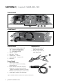
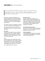
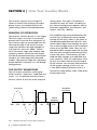
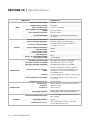
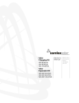
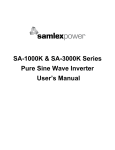
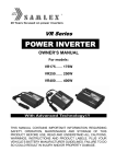
DC-AC
Inverter
Model:
SAM-450-12E
Owner's
Manual
Please read this
manual before
installing your
inverter
Owner's ManuaL | Index
Section 1
Important Safety Instructions................................................. 3
Section 2
Layout ............................................................................ 4
Section 3
Introduction............................................................................5
Section 4
How Your Inverter Works ...................................................... 6
Section 5
Installation - DC Input Power Source,
Grounding & Mounting ........................................................ 7
SECTION 6
Input, Output Connections & Operation ............................... 8
Section 7
Protective Features of the Inverter ....................................... 10
Section 8
Common Problems ............................................................. 11
Section 9
Trouble Shooting Guide ...................................................... 12
Section 10
Specifications .......................................................................14
Section 11
Warranty ......................................................................... 15
2 | SAMLEX AMERICA INC.
Section 1 | Important Safety Instructions
To ensure reliable service, your power
inverter must be installed and used
properly. Please read the installation and
operating instructions thoroughly prior
to installation and use. Pay particular
attention to the WARNING and CAUTION
statements in this manual.
The CAUTION statements advise against
certain conditions and practices that may
result in damage to your inverter. The
WARNING statements identify conditions
or practices that may result in personal
injury. Read All Instructions Before Using
This Power Inverter!
WARNINGS
TO REDUCE THE RISK OF FIRE, ELECTRIC
SHOCK, EXPLOSION OR INJURY
!
CAUTIONS
1. Do not use with positive ground
electrical systems (the majority of
modern automobiles, RVs, trucks and
boats are negative ground). Reverse
polarity connection will result in a
blown fuse and may cause permanent
damage to the inverter.
2. This inverter will not operate high
wattage appliances over the output
power limit or surge power limit.
3. Grounding the neutral will cause the
inverter to shut down. Do not operate
this inverter if it is wet. Do not install in
engine compartment – please install in
a well ventilated area.
4. This inverter is not tested for use with
medical devices.
1. Do not connect to AC distribution
wiring.
IMPORTANT CABLE
INFORMATION
2. Remove appliance plug from outlet
strip or turn off inverter before working
on the appliance.
Substantial power loss and reduced battery operating time results from inverters
installed with cables that are not able to
supply full power. Symptoms of low battery power can result from cables that are
either excessively long or an insufficient
gauge. The installer/operator should be
especially aware of the requirements to
maintain secure, tight, water-resistant electrical connections and to provide
for strain relief for DC cables and appliance wiring. Cable insulation must be the
appropriate type for the environment.
Multiple outlet power strips with
switches and circuit breakers interrupt
power only to the “hot” receptacle terminals. The “neutral” terminals remain
powered with respect to the“ground”
terminals.
3. Do not make any electrical connections
or disconnections in areas designatedas
IGNITION PROTECTED. This includes
12 VDC cigarette plug connections, and
terminal connections.
4. This is not a toy - keep away from
children.
5. DO NOT insert objects into air vents.
SAMLEX AMERICA INC. | 3
SECTION 2 | Layout: SAM-450-12E
Front Panel
2
1A
6
1B
1C
3
1
4
5
Back Panel
7
9
8*
Front Panel
Accessories
1. Universal AC output receptacle
1A - Current carrying prong
1B - Current carrying prong
1C - Grounding prong
2. ON/OFF Switch
3. Red LED - “Fault”
4. Green LED - “Power”
5. Yellow LED - “Input Fault”
6. USB port
10.Battery input cable set
with battery clamps
11.Battery input cable set
with cigar plug
10
Rear Panel
7. Red Thumb Screw
(M4 size) for Positive (+) battery
input terminal
8. Black Thumb Screw (M4 size) for
Negative (-) battery input terminal.
*NOTE: The Negative terminal is internally
bonded to the metal chassis of the inverter.
9. Opening for cooling fan discharge
Figure: SAM-450-12E Front & Back Panel Layout & Accessories
4 | SAMLEX AMERICA INC.
11
Section 3 | Introduction
Your new SAM Series power inverter is one in a series of the most
advanced DC to AC inverters available today. With proper care and
appropriate usage, it will give you years of dependable service in
your car, truck, RV or boat.
SAM Series inverters designed with a
universal protection circuit that provide
added safety features include automatic
shutdown, earth fault protection and a
low battery alarm to prevent damage to
your battery.
This power inverter is configured with the
latest low interference technology (L.I.T.),
Universal Protection Circuit (UP-Circuit)
and Soft Start circuit to improve inverter
operation.
UP-Circuit
Provides full automatic inverter and battery protection. This includes overheat
protection, battery protection, overload
protection, short circuit protection and
earth fault protection.
Soft Start Circuit
Provides three major features. First,
gradual voltage ramp-up during inverter
start-up. This eliminates failed cold starts
under load. Second, output that momentarily dips in voltage and quickly recovers.
This eliminates most shutdowns from
momentary overloads.
Load Controlled Cooling Fan
The fan will switch on automatically when
the load > 8 to 12W and switch off when
load drops below 8 to 12W.
USB Charging Port
A USB charging port rated at 5V, 500 mA
is provided for charging devices provided
with USB charging facility.
L.I.T.
Greatly improve the interference problems of common power inverter. Before
introduction of L.I.T., signal interference
may occur on TV pictures, audio system or
radio equipments. Now you can enjoy a
clean and powerful AC source!
SAMLEX AMERICA INC. | 5
SECTION 4 | How Your Inverter Works
utility power. This type of waveform is
suitable for most AC loads, including linear and switching power supplies used in
electronic equipment, transformers, and
motors. (See Fig. 1 below).
The inverter converts low voltage DC
(Direct Current) from a battery or other
power source to standard 230 volt AC
(Alternating Current) household power.
PRINCIPLE OF OPERATION
The inverter converts power in two stages.
The first stage is a DC to DC conversion
process that raises the low voltage DC at
the inverter input to around 300 volts DC.
The second stage is the actual inverter
stage that converts the high voltage DC
into 230 VAC, 50 Hz AC (RMS). The DCto-DC converter stage uses modern high
frequency power conversion techniques
that have replaced the bulky transformers
found in less technologically-advanced
models. The inverter stage uses advanced
power MOSFET transistors in a full bridge
configuration.
THE OUTPUT WAVEFORM
The AC output waveform of the SAM
Series inverter is known as “modified sine
wave”. It is a waveform that has characteristics similar to the sine wave shape of
The modified sine wave produced by the
inverter has an RMS (root mean square)
voltage of 230 volts, which is the same as
standard household power. Most AC voltmeters (both digital and analog) are sensitive to the average value of the waveform
rather than the RMS value. They are calibrated for RMS voltage under the assumption that the waveform measured will be
a pure sine wave. These meters will not
read the RMS voltage of a modified sine
wave correctly. They will read about 20 to
30 volts low when measuring the output
of the inverter. For accurate measurement
of the output voltage of this unit, use
a true RMS reading voltmeter such as a
Fluke 87III, Fluke 8060A, Fluke 77/99 series
or Beckman 4410.
Sine Wave
Modified
Sine Wave
Phase
(degrees)
0
-360 -270 -180
90
0
90
Fig. 1: Modified Sine Wave and Sine Wave Comparison
6 | SAMLEX AMERICA INC.
180
270
Section 5 | Installation - DC Input Power Source,
Grounding & Mounting
POWER SOURCE REQUIREMENTS
The power source must provide > 10.0
and < 15.5 VDC and must be able to supply the necessary current to operate the
load. The power source may be a battery
or a well-regulated DC power supply. To
obtain a rough estimate of the current (in
amperes) the power source must deliver,
simply divide the power consumption of
the load (in watts AC) by 10.
Example:
lf a load is rated at 100 watts AC, the
power source must be able to deliver:
100 / 10=10A
The inverter will provide you 230 VAC,
50 Hz when powered by a 12 VDC source
such as is found in a vehicle. This manual
does not describe all of the possible types
of battery configurations, battery charging configurations and battery isolation
configurations.
GROUNDING
For safety, the metal chassis of the inverter
is required to be grounded to the earth
ground or to the other designated ground
(For example, in a mobile RV, the metal
frame of the RV is normally designated as
the Negative DC ground).
Internally, the metal chassis of the inverter
is bonded (connected) to the Negative
DC input terminal (8). When the unit is
operated in a Negative Grounded Vehicle
System (the Negative of the vehicle battery is bonded to the metal chassis of the
vehicle), the metal chassis of the inverter
will be automatically bonded to the Vehicle Chassis Ground.
WARNINGS
If the inverter is not being used in a vehicle, please ensure that the Negative of the
battery is firmly bonded to Earth Ground
(through water pipe / Ground Rod / other
Earth grounding arrangement). This will
ensure that the chassis of the inverter is
firmly “grounded”. Use a # 8 AWG insulated stranded copper wire for the above
bonding.
Prongs (1A) and (1B) of the AC output
receptacle (1) are isolated from the metal
chassis of the inverter and the Vehicle /
Earth Ground. The grounding prong (1C)
is connected to the Leakage Detection
and Shutdown Circuit. This implementation and internal circuit design results
in elevated voltages of 80 to 150 VAC of
prongs (1A) / (1B) relative to prong (1C) or
to the chassis. Do not touch prongs (1A)
or (1B).
Connecting output from prongs (1A) or
(1B) to chassis or ground will result in
shut down due to activation of leakage
protection circuit.
Do not connect to AC distribution wiring
where the neutral is bonded to earth
ground. Inverter will shut down due to
leakage protection
SAMLEX AMERICA INC. | 7
Section 5 | Installation - DC Input Power Source,
Grounding & Mounting
INSTALLATION NOTES
WARNING
Ensure ventilation when using batteries.
Batteries may generate flammable gas
during charging or discharging.
MOUNTING
The inverter has four slots in its mounting
bracket that allow the unit to be fastened
against a bulkhead, floor, wall or other
flat surface. Ideally, the mounting surface
should be cool to the touch.
It is more electrically efficient to use
longer AC wiring than DC wiring, so install
the inverter as close as possible to the
12 VDC power source.
If inverter is to be installed in a moving
vehicle, we strongly recommends that the
inverter be shock-mounted either on the
floor (in a clear, safe area) or on a secure
flat surface.
!
CAUTION
The power inverter must be connected
only to batteries with a nominal output
voltage of 12 volts. The unit will not
operate from a 6 volt battery, and will
sustain permanent damage if
connected to a 24 volt battery.
CAUTION
Loose connectors may cause overheated
wires and melted insulation. Check to
make sure you have not reversed the
polarity. Reverse polarity connection will
result in a blown fuse and may cause
permanent damage to the inverter.
Section 6 | Input, Output Connections
& Operation
OPERATING ENVIRONMENT
The inverter should only be used in locations that meet the following criteria:
DRY - Do not allow water or other liquids to
come into contact with the power inverter. In
marine applications, do not install the inverter
below or near the waterline and keep the
inverter away from moisture.
COOL - Ambient air temperature should be
between 32°F (0°C) non-condensing, and 105°F
(40°C). Do not place the inverter on or near a
heating vent or any piece of equipment which is
generating heat above room temperature. Keep
the inverter away from direct sunlight.
8 | SAMLEX AMERICA INC.
VENTILATED - Keep the area surrounding
the inverter clear to ensure free air circulation
around the unit. Do not place items on or over
the inverter during operation. The unit will
shut down if the internal temperature exceeds
operating temperatures.
SAFE - Do not use the inverter near flammable
materials or in any locations that may accumulate flammable fumes of gases.
DC INPUT CONNECTIONS
12 VDC input voltage from the battery is
fed to the DC input terminals (7, 8). For
feeding 12 VDC battery input, two sets of
Section 6 | Input, Output Connections
& Operation
cables (10, 11) have been provided
(see page 4):
• Use the battery input cable with the
battery clamps if the full 450 W output
is required. Ensure that a 60 A to 70A
Class T fuse is used in series with the
battery Positive wire as close to the battery as possible (within 7").
• Use the battery cable with the cigar
plug if the maximum load is less than
80 W. Please note that the cigar plug
has an internal fuse rated at 8 A and
this fuse will blow if the wattage of the
AC load is more than 80 W. The cigar
plug wiring in the vehicle is normally
protected by a 10 A fuse inside the fuse
box of the vehicle
• Ensure that the connections are tight
AC OUTPUT CONNECTIONS
The AC output of the inverter is fed
through a Universal, 2-Pole Grounding
Receptacle (1). Internally, the 2 AC current
carrying conductors providing 230 VAC,
50 Hz voltage from the output section
of the inverter are wired to the 2 current
carrying prongs (1A and 1B) of the receptacle and BOTH THE PRONGS (1A) AND
(1B) ARE ISOLATED FROM THE CHASSIS
OF THE INVERTER AND VEHICLE / EARTH
GROUND. Voltage measured between the
2 current carrying prongs (1A) and (1B)
will read 230 VAC, 50 Hz (see page 4).
POWERING ON AC LOADS
After the inverter is switched on, it takes
a finite time for it to become ready to
deliver full power. Always switch on the
load(s) after a few seconds of switching
on the inverter. Avoid switching on the inverter with the load already switched on.
This may prematurely trigger the overload
protection. When a load is switched on, it
may require initial higher power surge to
start. If multiple loads are being powered,
they should be switched on one by one so
that the inverter is not overloaded by the
higher starting surge.
OPERATION
Plug the cord from the equipment you
wish to operate into the AC receptacle. The
green LED indicator lights to indicate that
the inverter is functioning. Make sure the
combined load requirement of your equipment does not exceed inverter’s output
rating.
Do not connect the power inverter to
household or RV AC distribution wiring. Do
not connect the power inverter to any AC
load circuit in which the neutral conductor
is connected to ground (earth) or to the
negative of the DC (battery) source.
RATED VERSUS ACTUAL CURRENT
DRAW OF EQUIPMENT
Most electrical tools, appliances and audio/
video equipment have labels that indicate
the power consumption in amps or watts.
Be sure that the power consumption of the
item you wish to operate is less than inverter’s power. (If the power consumption
is rated in amps AC, simply multiply by the
AC volts (230) to determine the approximate wattage). The inverter will shut down
if it is overloaded. The overload must be removed before the inverter will restart. Resistive loads are the easiest for the inverter
to run. However, larger resistive loads, such
as electric stoves or heaters, usually require
more wattage than an average sized
inverter can deliver. Inductive loads, such
as TV’s and stereos, require more current
to operate than do resistive loads of the
same wattage rating. Induction motors, as
well as some televisions, may require 2 to 6
SAMLEX AMERICA INC. | 9
Section 6 | Input, Output Connections
& Operation
times their wattage rating to start up. The
most demanding in this category are those
that start under load, such as compressors and pumps. To restart the unit after a
shutdown due to overloading, remove the
overload if necessary turn the power switch
OFF then ON.
Section 7 | Protective Features of the Inverter
OVER TEMPERATURE PROTECTION
If the temperature inside the inverter is
too high, the unit will automatically shut
down. Allow the unit to cool for at least
15 minutes before restarting. Unplug unit
while cooling. Status of LEDs and buzzer:
Red LED “FAULT” (3) ................................. OFF
Green LED “Power” (4) .............................. ON
Yellow LED “Input Fault”(5) ...................... ON
Buzzer.......................................................... OFF
Reset............................. Auto-reset on cooling
LOW DC INPUT VOLTAGE PROTECTION
This condition is not harmful to the inverter but could damage the power source.
The inverter automatically shuts down
when input voltage drops to 10.0 volts.
Status of LEDs and buzzer:
Red LED “FAULT” (3) ..................................OFF
Green LED “Power” (4)...............................OFF
Yellow LED “Input Fault” (5).......................ON
Buzzer............................................................ON
Reset*.............................................. Auto- reset
*When DC input voltage rises to 11.5 VDC
HIGH DC INPUT VOLTAGE PROTECTION
The inverter will automatically shut down
when the input voltage exceeds 15.5 volts
DC. Input voltage exceeding 16 volts could
damage the inverter. Status of LEDs and
buzzer:
Red LED “FAULT” (3)...................................OFF
Green LED “Power” (4)...............................OFF
10 | SAMLEX AMERICA INC.
Yellow LED “Input Fault” (5).......................ON
Buzzer...........................................................OFF
Reset*............................................... Auto-reset
* When DC input voltage < 15.5 V
OVERLOAD PROTECTION
The inverter will automatically shut down
when the continuous draw exceeds rated
watts.
Red LED “FAULT” (3)ON
Green LED “Power” (4)ON
Yellow LED “Input Fault” (5)......................OFF
Buzzer...........................................................OFF
Reset*...........................................Manual reset
*Switch OFF, wait for around 3 min, switch ON
SHORT CIRCUIT PROTECTION
The inverter will shut down. Remove the
short circuit and restart inverter. Status of
LEDs and buzzer:
Red LED “FAULT” (3)....................................ON
Green LED “Power” (4)................................ON
Yellow LED “Input Fault” (5)......................OFF
Buzzer...........................................................OFF
Reset*...........................................Manual reset
*Switch OFF, wait for around 3 min, switch ON
EARTH FAULT PROTECTION
This inverter complies with the standard
current leakage allowance. When large
current leakage to earth terminal occurs,
the protection circuit is activated and
shuts down the inverter, which prevent s
electric shock. Status of LEDs and buzzer:
Section 7 | Protective Features of the Inverter
Red LED “FAULT” (3)....................................ON
Green LED “Power” (4)................................ON
Yellow LED “Input Fault” (5)......................OFF
Buzzer...........................................................OFF
Reset*...........................................Manual reset
*Switch OFF, wait for around 3 min, switch ON
LOW INPUT VOLTAGE ALARM
An alarm will sound when the DC input
voltage from the battery drops to 10.5
volts. This is an indication that the battery
needs to be recharged. The user should
stop operation of the electronic device at
this time since the inverter will shut down
shortly thereafter, when the battery voltage drops to 10 volts. Start your engine to
recharge the battery. Status of LEDs and
buzzer:
Red LED “FAULT” (3) ..................................OFF
Green LED “Power” (4)................................ON
Yellow LED “Input Fault” (5)......................OFF
Buzzer............................................................ON
Reset................................................ Auto- reset
If the low DC input voltage alarm sounds
when the battery is fully charged, follow
the steps for solving lack of output power
in the Troubleshooting guide. The alarm
will sound when the inverter is overloaded, in thermal shutdown, or if there
is an excessive voltage drop between the
battery and inverter.
NOTE: It is normal for the alarm to sound while
the unit is being connected to, or disconnected
from, the power source. This is not indicative of
a problem.
Section 8 | Common Problems
POWER TOOLS AND MICROWAVE
OVENS WON’T START
Read the information panel on each power tool carefully to accurately determine
the tool’s input wattage. Please remember
that the power needed to start the power
tool may be as much as 2 to 6 times its
continuous wattage requirements.
“BUZZING” SOUND IN
AUDIO SYSTEMS
Some inexpensive stereo systems and
“boom boxes” emit a buzzing sound from
their speakers when operated from the
power inverter. This occurs because the
power supply in the electronic device does
not adequately filter the modified sine
wave produced by the inverter. The only
solution to this problem is to use a higher
quality sound system that incorporates a
higher quality power amplifier supply.
TELEVISION INTERFERENCE
The inverter is shielded to minimize interference with TV signals. The problem may
not be with the inverter. However, in some
instances, some interference may still be
visible, particularly with weak TV signals.
Try the following corrective measures:
- Position the inverter as far as possible
from the television, the antenna and
the antenna cables. Use an extension
cable, if necessary.
- Adjust the orientation of the inverter,
the antenna cables and the TV power
cord to minimize interference.
- Make sure that the antenna feeding
the television provides an adequate
(“snow free”) signal and that high
quality, shielded antenna cable is used.
- Do not operate high-power appliances
or tools when you are watching TV.
The advanced technology of SAMLEX, L.I.T greatly reduces the
possibility of interference with TV signals and audios.
SAMLEX AMERICA INC. | 11
Section 9 | Troubleshooting Guide
ISSUE: No AC Output - Green LED is NOT ON, Yellow LED is ON, Buzzer is ON POSSIBLE CAUSES:
Low DC input voltage shut down due to DC input voltage at the inverter terminals dropping
below 10.0 VDC. Auto reset when the DC input voltage is > 11.5 VDC.
SUGGESTED REMEDIES:
•
Low battery terminal voltage. Recharge the battery. If battery voltage does not rise to fully
charged voltage even after long charging time, replace the battery.
•
Excessive drop in DC input wires due to thin DC input wires. Check firmness of connections and
increase wire size
•
If the battery terminals read higher voltage at no load but the terminal voltage drops appreciably when the load is turned on, the battery may have sulfated due to undercharging.
Equalize the battery (only flooded or wet cell types).
ISSUE: No AC Output - Green LED is NOT ON, Yellow LED is ON, Buzzer is OFF
POSSIBLE CAUSES:
1. Over temperature shutdown
2. High DC input voltage shut down. DC input voltage is > 15.5 V. Auto-reset when voltage
< 15.5 VDC
SUGGESTED REMEDIES:
IF Cause #1:
•
Fan failure: Check that the fan runs when the unit is loaded to > 8 to 12 W
•
Ventilation openings are blocked: Remove any obstructions in the ventilation openings
•
Not enough cool, replacement air: Install the unit in an open, cool and dry area
•
High ambient temperature > 40 C: The temperature of the unit will slowly rise even if the
fan is working
IF Cause #2:
•
The battery charger may be charging at > 15.5 V, especially during Equalization. Disconnect
the DC input of the inverter when equalizing the batteries > 15.5 VDC
•
It is likely that 24 VDC battery has been connected instead of 12 VDC battery. ONLY USE A
NOMINAL 12 VDC BATTERY WITH THIS PRODUCT.
ISSUE: No AC Output - Green, Red and Yellow LEDs are NOT ON and Buzzer is OFF
POSSIBLE CAUSE: No DC input power.
SUGGESTED REMEDIES:
•
Check DC voltage at the DC input terminals
•
If DC input cable with cigar plug is being used, the 8 A fuse in the front of the cigar plug may
have blown if the load being powered was > 80 W. Replace the fuse in the cigar plug, if blown.
•
If powered from the cigar receptacle in a vehicle, the fuse in the vehicle that is supplying
the cigar receptacle may have blown. Check and replace. After replacing the fuse, check DC
input voltage at the inverter terminals. If DC input voltage is available, the internal fuses may
have blown. Call Technical Support.
•
If DC input cable with battery clamps is being used without inline fuse, the internal DC fuses
in the inverter may have blown. Call technical support
•
If DC input cable with battery clamps is being used with inline fuse, check the inline fuse and
replace if blown. If the fuse is intact, the internal DC fuses in the inverter may have blown.
Call technical support.
12 | SAMLEX AMERICA INC.
ISSUE: No AC Output - Green LED is ON, Red LED is ON, Yellow LED is OFF
and Buzzer is OFF POSSIBLE CAUSES:
1. Inverter has shut down due to internal short circuit / overload
2. Inverter has shut down due to short circuit / overload in the AC load connected to the inverter
3. Inverter has shut down due to leakage in the AC Load
SUGGESTED REMEDIES:
•
Switch off and disconnect the load
•
The unit will be latched in shutdown condition and will require manual reset. Switch off the
On / Off switch and wait for 3 minutes. Switch on the On / Off switch to reset the unit
IF Cause #1:
•
If the unit shows the same symptoms on no load, the unit is defective. Call Tech Support
IF Cause #2:
•
Check that there is no short circuit in the AC load and that the rating of the load is not > 450
W continuous or > 900 W surge.
•
Power a different good load of up to 450 W and confirm that the unit does not shut down
IF Cause #3:
•
Power a different good load of up to 450 W and confirm that the unit does not shut down
•
Check that there is no leakage in the load that created shut down. Leakage will occur if
there is a direct short or electrical path from live, current carrying section in the load to the
chassis of the load. Remove faulty load.
ISSUE: AC Output is Available - Green LED is ON, Red LED is OFF, Yellow LED is OFF,
Buzzer is ON
POSSIBLE CAUSE: Low DC input voltage alarm due to DC input voltage < 10.5 VDC. Will automatically reset when > 10.5 VDC.
SUGGESTED REMEDIES:
•
Low battery terminal voltage. Recharge the battery. If battery voltage does not rise to fully
charged voltage even after long charging time. Replace the battery
•
Excessive drop in DC input wires due to thin DC input wires. Check firmness of connections
and increase wire size
•
If the battery terminals read higher voltage at no load but the terminal voltage drops appreciably when the load is turned on, the battery may have sulfated due to undercharging.
Equalize the battery (only flooded or wet cell types).
ISSUE: Some loads do not power up properly.
POSSIBLE CAUSES: If these are connected permanently to the inverter, are in ON condition always
and these are switched ON and OFF using the On / Off Switch of the inverter. Extremely high reactive inrush currents during the voltage ramp up of soft start phase on switching on of the inverter
drives the inverter into hiccup and subsequent overload.
SUGGESTED REMEDIES:
•
Always switch on the inverter first and then the AC load.
•
In order to reduce the inrush current, add a small resistive load like incandescent lamp and
this may allow normal startup
ISSUE: AC output voltage reads low ( 192 to 208 VAC) when measured with
an ordinary voltmeter
POSSIBLE CAUSE:
The voltmeter being used is not designed to read the true RMS value of modified sine wave-form
SUGGESTED REMEDY:
•
Use a voltmeter which is designed to measure “true RMS values” like Fluke 87,
Fluke 8060A, etc.
SAMLEX AMERICA INC. | 13
Section 10 | Specifications
Model No.
SAM-450-12E
Battery System Voltage
Nominal Input Voltage
INPUT
Input Voltage Range
Input Current At Continuous
Power
Input Current At No Load
Dc Side Grounding
> 10.5 to < 15.5 VDC
41.3 A to 43.3 A
0.25 A to 0.35 A
DC Negative (-) input terminal bonded
to chassis
Output Voltage Wave Form
Modified Sine Wave
230 VAC + 10% / -2%; 50 Hz ± 5%
Both AC current carrying conductors
isolated from chassis
Output Power, Continuous
(Resistive Load)
450 W
Output Power, Surge
(< 1 Sec, Resistive Load)
900 W
Peak Efficiency
(At 50% Of Continuous Power)
Usb Charging Port
Low Input Voltage Alarm
PROTECTIONS
12.5 VDC
Output Voltage; Frequency
Ac Output Side Grounding
OUTPUT
12 VDC
90%
5 VDC, 500mA
10.5 VDC. Auto reset at > 10.5 VDC
Low Input Voltage Shutdown
10.0 VDC. Auto reset at 11.5 VDC
High Input Voltage Shutdown
15.5 VDC. Auto reset at < 15.5 VDC
Overload And Leakage Shut
Down
Cooling
Over Temperature Shutdown
Internal Input Fuse, 32 V
Battery Input
Ac Output
Usb Output
CONNECTIONS
Accessories Supplied
Operating Temperature Range
Operating Humidity
GENERAL
Dimensions (L X W X H)
Weight
14 | SAMLEX AMERICA INC.
Latches in shutdown condition. Manual
reset by switching off the ON/OFF switch,
waiting for 3 minutes and switching on
the On/Off switch
Load controlled fan. Comes on at 8 to 12W
By sensing internal hot spot. Auto reset
on cooling
70 A (2 X 35 A)
Red (+) & Black (-) thumb screws; M4 size
Universal outlet
USB connector
Battery input cable set with battery clamps
Battery input cable set with cigar plug
0 to 25 C at 100% loading; 26°C to 35°C at
80% loading
< 80%
154 x 154 x 46 mm; 6 x 6.1 x 1.8 inches
(size includes protrusions)
0.6 kg.; 1.3 lb.
Section 11 | Warranty
2 YEAR Limited Warranty
SAM-450-12E manufactured by Samlex
America, Inc. (the “Warrantor“) is warranted to be free from defects in workmanship and materials under normal use and
service. The warranty period is 2 years for
the United States and Canada, and is in effect from the date of purchase by the user
(the “Purchaser“). Warranty outside of the
United States and Canada is limited to 6
months. For a warranty claim, the Purchaser should contact the place of purchase to
obtain a Return Authorization Number.
The defective part or unit should be
returned at the Purchaser’s expense to the
authorized location. A written statement
describing the nature of the defect, the
date of purchase, the place of purchase,
and the Purchaser’s name, address and telephone number should also be included.
If upon the Warrantor’s examination, the
defect proves to be the result of defective
material or workmanship, the equipment will be repaired or replaced at the
Warrantor’s option without charge, and
returned to the Purchaser at the Warrantor’s expense. (Contiguous US and Canada
only) No refund of the purchase price will
be granted to the Purchaser, unless the
Warrantor is unable to remedy the defect
after having a reasonable number of opportunities to do so. Warranty service shall
be performed only by the Warrantor. Any
attempt to remedy the defect by anyone
other than the Warrantor shall render this
warranty void. There shall be no warranty
for defects or damages caused by faulty
installation or hook-up, abuse or misuse
of the equipment including exposure to
excessive heat, salt or fresh water spray,
or water immersion. No other express
warranty is hereby given and there are no
warranties which extend beyond those described herein. This warranty is expressly
in lieu of any other expressed or implied
warranties, including any implied warranty of merchantability, fitness for the ordinary purposes for which such goods are
used, or fitness for a particular purpose, or
any other obligations on the part of the
Warrantor or its employees and representatives. There shall be no responsibility
or liability whatsoever on the part of the
Warrantor or its employees and representatives for injury to any persons, or
damage to person or persons, or damage
to property, or loss of income or profit,
or any other consequential or resulting
damage which may be claimed to have
been incurred through the use or sale of
the equipment, including any possible
failure of malfunction of the equipment,
or part thereof. The Warrantor assumes
no liability for incidental or consequential
damages of any kind.
Samlex America Inc. (the “Warrantor”)
www.samlexamerica.com
SAMLEX AMERICA INC. | 15
Contact
Information
Toll Free Numbers
Ph: 1 800 561 5885
Fax: 1 888 814 5210
Local Numbers
Ph: 604 525 3836
Fax: 604 525 5221
Website
www.samlexamerica.com
USA Shipping Warehouse
Kent WA
Canadian Shipping Warehouse
Delta BC
Email purchase orders to
[email protected]
11002-SAM-450-12E-0412