1
QUARTZ TIME RECORDER
Simplex 500
OPERATION MANUAL
Bescheinigung des Herstellers/Importeurs
Dies Gerät entspricht den Bedingungen der Niederspannungs-Vorschrift
73/23/EEC und dem EMVG nach 89/336/EEC.
This unit complies with the Low Voltage Directive 73/23/EEC and the
EMC Directive 89/336/EEC.
Maschinenl ärminformationsverordnung 3. GSGV, 18.01.1991:
Der arbeitsplatzbezogene Schalldruckpegel beträgt 70 dB (A) oder
weniger gemäß ISO 7779.
Die zugeho¨rige Steckdose muß nahe beim Gerät angebracht und leicht
zugänglich sein.
1. The details of this Operation Manual are subject to change w ithout previous
notification.
2. This Operation Manual has been prepared with the utmost care to cover all aspects of
the time recorder's use.
If you feel, however, that some explanations are inadequate, unclear, or difficult to
understand, please do not hesitate to contact the dealer or the shop from which you
have purchased your Time Recorder.
3. Be sure to use your Time Recorder after you have fully understood the hardware and
software specifications and limits.
4. No part of this publication may be reproduced, stored in a r etrieval system, or
transmitted, in any form or by any means, mechanical, photocopying, recording or
otherwise.
Replace battery with TOSHIBA, part no. CR 2450 THC only.
Use of another battery may present a risk of fire on explosion.
Place the time recorder close to the wall outlet so that it is easily accessible to
disconnect.
TABLE OF CONTENTS
1. PRECAUTIONS
1
2. FEATURES
3
3. BEFORE USING THE TIME RECORDER
4
Accessories
4
Features
4
Installing the Ribbon Cassette
5
Wall Mounting
6
Environmental Conditions
6
4. DAILY OPERATIONS
7
5. SETTING
8
Preparation for setting
8
Setting the Pay Period
9
Setting the Date and the Time, 1/60 or 1/100 printing,
and the 12/24 HOUR format
12
Setting the Day Advance Time
14
Setting the Daylight Saving Time (D.S.T.)
15
Setting the Time Table Program
18
Setting Number of Seconds for External Time Signal
25
Resetting
26
6. CONNECTING TO AN EXTERNAL TIME SIGNAL
27
7. INSERTING THE Ni-Cd BATTERY
28
8. TROUBLESHOOTING
29
9. SPECIFICATIONS
30
10. TIME CARD SPECIFICATIONS
31
1. PRECAUTIONS
This operation manual is prepared for safe and proper use of the unit.
Please follow all the instructions to avoid possible danger to yourself
or others and damage to the unit.
Signs
Various warnings and cautions are provided throughout this manual along with signs.
Remember each sign and its explanation listed below for your safety and proper
operation of the unit.
Warning
Improper handling may cause bodily accidents including
death and serious injury.
Caution
Improper handling may harm the human body or material.
Improper handling may cause electric
shock DANGER.
"Must-Do" sign.
DO NOT disassemble the unit.
Be sure to remove the line cord plug
from the outlet.
"Don't" sign.
Warning
Do not disassemble the unit. There is a high voltage present inside, possibly leading to an
electric shock.
Do not modify the unit. Modifications may cause a fire and/or electric shock.
If any anomaly occurs, for example, heat or smoke is generated or an odor is emitted, unplug
the unit immediately and contact your dealer for servicing. There is a danger that further use
may cause a fire or electric shock.
Do not use any voltage of the power source other than designated.
Do not share a single outlet with another plug. These may lead to fire or shock hazards.
Do not damage, break, or modify the power cord. Do not put a heavy object on, pull, or
forcefully bend the cord, either. These may damage the cord, possibly resulting in a fire or
electric shock.
1
2. FEATURES
• The time table program provides the following functions:
•Automatic
switching between black and red printing
The two-color printing system makes it possible to easily see an
employee's in and out time.
•Automatic activation of an external time signal
The unit can be programmed to externally output a signal when
it's time to start or quit, or for breaks.
•Automatic switching among six print columns (Columns 1-6)
The auto-switching function of a column to print records in
prevents punching failure or error.
• It has three selectable pay periods : weekly, bi-weekly or monthly.
• The monthly card automatically senses the front or back of the card,
therefore assuring no erroneous date printing.
• If the closing date for payroll processing does not fall on the end
of a month, the unit can be set to any desired closing date.
• The day advance time function makes it possible to print out on
•
•
the same line of a time card for the previous working day even
when leaving the office after midnight.
An easy-to-see analog clock is provided on its front for users'
convenience.
User-friendly operation and easy setting enhance users' comfort.
3
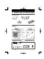
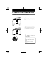
3. BEFORE USING THE TIME RECORDER
Accessories
Operation Manual
Wall mount fittings
Keys
Ribbon cassette
Features
<Front view>
<Back view>
Card slot
Display
Control button
Panel cover
Panel open button
(at both sides
of the unit)
Key hole
Analog clock
Wall-mounting
hole
<Display>
Day of the week indication
Daylight saving time indication
12Hr.
SU
MO
TU
WE
TH
FR
SA
12 HOUR indication
4
Current date
Current time
AM or PM
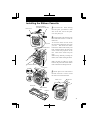
Installing the Ribbon Cassette
Panel cover
Panel open button
(at both sides of the unit)
1
Unlock the unit. While holding
down the panel, open buttons at both
sides of the unit, and lift the panel
cover away from you.
2 Turn the knob on the cassette in the
Key hole
Panel house
arrow-indicated direction to make the
ribbon taut.
To insert the ribbon cassette inside
the unit, lift the panel house away from
you first. Then thread the ribbon
between the ribbon mask and the print
head. Slide the latch on the lower side
of the cassette into projections on the
unit. Then let the cassette snap into
place.
When having difficulty inserting the
ribbon, insert it while turning the knob.
Make sure that the ribbon is placed
between the print head and the ribbon
mask as illustrated in the figure at left.
Ribbon cassette
Print head
3
Put the panel cover on the hook at
the back of the unit. Lower it toward
this side to close and lock the unit.
Panel cover
Print head
Ribbon mask
Ribbon
5
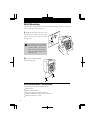
Wall Mounting
The unit can be mounted on a wall using the supplied mounting fittings. To mount the
unit on a wall, take the following steps:
1
Install the two larger screws into a wall
3.94 inches (10 cm) apart. Be sure to keep
about 0.12 inch (3 mm) of the screw head
out of the wall.
The supplied screws are intended
for use on a thick wooden wall or
wooden column. Do not use
them on any other materials.
There is a danger that the unit
may come off.
4
3.9
(3m 0.1
m) 2"
2 Mount the wall mount fittings
as shown on the right.
Environmental Conditions
Avoid placing the unit in environments that are:
humid or dusty
exposed to direct sunshine
subject to frequent or continuous vibrations
outside the temperature range between -5° and 45°C
affected by chemicals or ozone
•
•
•
•
•
6
)
cm
0
" (1
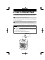
4. DAILY OPERATIONS
Once the AC line cord is plugged into the outlet, the unit can be used immediately as
basic operation has been pre-set at the factory, including the time and the closing date.
See "3 BEFORE USING THE TIME RECORDER".
It is easy to operate the unit. Just insert a time card. The card is then automatically
pulled in, printed and then ejected.
Do not let any metallic object get into the slot, including paper clips. Do not
forcefully push in a card, either. These may cause the unit to malfunction.
If any setting needs to be changed, such as for a closing date or other items, See "5.
SETTING".
The unit is designed to print in black on the first column when no time table program
is set. Usually it is necessary to set the time table program in order to automatically
print colors and to change columns to print records in. For a temporary change of a
column, however, manual operation is also available: just push the button for any
desired column before inserting a time card.
The button for the column selected lights up.
7
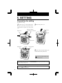
5. SETTING
Preparation for setting
To prepare for setting:
1
2
Unlock the unit. While holding down
Remove the panel cover.
the panel, open buttons at both sides of the
unit and lift the panel cover away from
you.
Panel open button
(at both sides of the unit)
Panel cover
Key hole
Panel house
Display
Control button
3
Make settings using the display and
control buttons at the panel house.
Be sure to make settings with
the power on.
Upon opening the panel cover, the PAY ENDING button lights up and the unit is in
the pay ending setting mode.
Make sure to press SET at the completion of each setting. Contents are NOT stored in
memory if SET is not pressed.
8
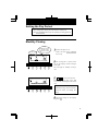
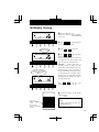
Setting the Pay Period
• The closing date is factory-set at the end of a month (31st).
• The PAY ENDING button stays lit up during its setting operation.
Monthly Closing
Card type
00 Monthly closing
01 Weekly closing
02 Bi-weeky closing
Closing date
12Hr.
SU
MO TU
WE
TH
FR
1 Remove the panel cover.
Make sure that PAY ENDING
stays lit up.
SA
1/60
1/100
YEAR MONTH
RED/BLK. EX.ALM
PAY ENDING
DAY
COL.
HOUR
DATE/TIME DAY ADV.TIME
MINUTE
D.S.T
SECOND/CARD
PROGRAM
2 The closing date is shown at the
EXT.ALARM
SELECT
SET
12Hr.
SU
MO TU
WE
TH
FR
3
or
to select date desired.
Example: If closing date is the 20th
every month, set the digits on the left at
"20".
SA
1/60
1/100
YEAR MONTH
RED/BLK. EX.ALM
PAY ENDING
SELECT
DATE/TIME
DAY
COL.
DAY ADV.TIME
HOUR
MINUTE
D.S.T
SECOND/CARD
PROGRAM
left on the display, and the card type
at the right.
The card type for monthly closing is
"00".
EXT.ALARM
SET
Always select the 31st in the case of
month-end closing, which is normally
factory-set unless you change the
setting.
4 Check the settings on the display
and press SET .
9
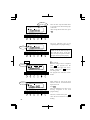
Weekly Closing
12Hr.
SU
MO TU
WE
TH
FR
1 Remove the panel cover.
SA
1/60
Make sure that the PAY ENDING
button stays lit up.
1/100
YEAR MONTH
RED/BLK. EX.ALM
PAY ENDING
DATE/TIME
DAY
COL.
HOUR
DAY ADV.TIME
MINUTE
SECOND/CARD
D.S.T
PROGRAM
EXT.ALARM
SELECT
SET
2 Press
or
to cause the digits
at the right to flash ("00") .
Weekly closing
12Hr.
SU
MO TU
WE
TH
FR
3 Press
SA
or
to select "01".
1/60
1/100
YEAR MONTH
RED/BLK. EX.ALM
PAY ENDING
DATE/TIME
DAY
COL.
HOUR
DAY ADV.TIME
MINUTE
SECOND/CARD
D.S.T
PROGRAM
EXT.ALARM
SELECT
SET
4 Press
Today is printed on
the second line
from the top.
12Hr.
SU
MO TU
WE
TH
FR
SA
1/60
1/100
YEAR MONTH
RED/BLK. EX.ALM
PAY ENDING
DATE/TIME
DAY
COL.
HOUR
DAY ADV.TIME
MINUTE
D.S.T
SECOND/CARD
PROGRAM
SELECT
EXT.ALARM
SET
or
to cause the digits
at the left to flash.
Today's printing line can be set at any
line from above on the weekly card, by
referring to the example below.
Example: Assume that today is
Tuesday, January 9, 2001 and the
closing date is Sunday.
As illustrated in the figure on the left,
today's printing line is set at the second
line from the top since Sunday
becomes the closing date if Sunday,
Januar 14, 2001 is set at the bottom
line.
Press
to set the right-side number
of the display at "02".
5 Check the settings on the display
and press SET .
IN
Today
Tuesday, January 9, 2001
Set closing day
Sunday, January 14, 2001
10
1
2
3
4
5
6
7
OUT
IN
OUT
IN
OUT
Use Weekly Cards for weekly closing.
The day of the week and time are
recorded on the card.
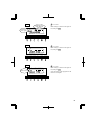
Bi-Weekly Closing
12Hr.
SU
MO TU
WE
TH
FR
1 Remove the panel cover.
SA
1/60
Make sure that the PAY ENDING
stays lit up.
1/100
YEAR MONTH
RED/BLK. EX.ALM
PAY ENDING
DATE/TIME
DAY
COL.
HOUR
DAY ADV.TIME
MINUTE
D.S.T
SECOND/CARD
PROGRAM
EXT.ALARM
SELECT
SET
SU
MO TU
WE
TH
FR
SA
1/100
PAY ENDING
DATE/TIME
DAY
COL.
HOUR
DAY ADV.TIME
MINUTE
D.S.T
SECOND/CARD
PROGRAM
EXT.ALARM
SELECT
SET
Today is printed on
the ninth line from
the top.
12Hr.
SU
MO TU
WE
TH
FR
SA
1/60
1/100
YEAR MONTH
RED/BLK. EX.ALM
PAY ENDING
DATE/TIME
DAY
COL.
HOUR
DAY ADV.TIME
MINUTE
D.S.T
or
to select "02".
4 Press
1/60
YEAR MONTH
RED/BLK. EX.ALM
or
to cause the digits
at the right to flash "00".
3 Press
Bi-weekly closing
12Hr.
2 Press
or
to cause the digits
at the left to flash.
Today's printing line can be set at any
line from above on the bi-weekly card
by referring to the example below.
Example:
Assume that today is
Tuesday, January 9, 2001 and the
closing date is this Sunday, January 14,
2001. Therefore, today corresponds to
the second Tuesday of this pay period.
As illustrated in the left figure, today's
printing line is set at the ninth line from
the top if Sunday, January 14, 2001 is
set at the bottom line.
SECOND/CARD
PROGRAM
EXT.ALARM
SELECT
SET
Press
or
to set the right
number of the display at "09".
5 Check the settings on the display
and press SET .
IN
Today
Tuesday, January
9, 2001
Set closing day
Sunday, January
14, 2001
1
2
3
4
5
6
7
8
9
10
11
12
13
14
OUT
IN
OUT
IN
OUT
Use bi-weekly cards for bi-weekly
closing.
The day of the week and time are
recorded on the card.
11
Setting the Date and the Time,
1/60 or 1/100 printing, and
the 12/24 HOUR format
The DATE/TIME button stays lit up during its setting operation.
1/60, 1/100 printing
12Hr.
SU
MO TU
1
Press SELECT to illuminate the
second button from the left,
DATE/TIME .
Date is indicated at the left, and time at
the right on the display.
To set the number, the digits must
flash.
Time
WE
TH
FR
SA
1/60
1/100
YEAR MONTH
RED/BLK. EX.ALM
Date
PAY ENDING
DATE/TIME
DAY
COL.
HOUR
DAY ADV.TIME
MINUTE
D.S.T
SECOND/CARD
PROGRAM
EXT.ALARM
SELECT
SET
2 To set date
Press
or
to cause digits to flash
and press
or
to select the
desired date.
Example: For October 21, 2001, adjust
the digits to "01-10-21".
3 To set time
Press
or
to cause the digits to
flash and press
or
to select the
desired time.
When the hour and minute are entered,
the second indication is automatically
reset at "00".
How to set 12 hour format
12 HOUR format
12Hr.
SU
MO TU
WE
PM
TH
FR
When you want to apply 12 hour
format both on LCD time and
printing format on the time card,
select 12 hour format first as
described below.
SA
1/60
1/100
YEAR MONTH
RED/BLK. EX.ALM
PAY ENDING
SELECT
12
DATE/TIME
DAY
COL.
DAY ADV.TIME
HOUR
MINUTE
D.S.T
SECOND/CARD
PROGRAM
EXT.ALARM
SET
Press
or
to cause the bar
under "12 Hr." to flash and press
or
to select 12 hour format.
Check the settings on the display and
press SET .
Thereafter press
or
to cause
the digits indicating hour to flash,
then follow step 3, above.
12Hr.
SU
MO TU
WE
TH
FR
4
SA
1/60
1/100
YEAR MONTH
RED/BLK. EX.ALM
PAY ENDING
DATE/TIME
DAY
COL.
DAY ADV.TIME
HOUR
MINUTE
D.S.T
SELECT
Example of printing:
In the case of 14:58
1/60 indication 14:58
1/100 indication 14.98
SECOND/CARD
PROGRAM
EXT.ALARM
Setting for 1/60 or 1/100 printing
Press
or
to cause the digits at
the upper left to flash.
Press
or
to select the printing
between 1/60 or 1/100.
SET
5 Check the settings on the display
and press SET .
13
Setting the Day Advance Time
The day advance time refers to the time when printing shifts to the next line on a time
card for the next day. This function, if printed before the set day advance time, enables
the time record to print on the same line of the previous working day even if leaving time
is after midnight.
• The day advance time is factory-set at 5:00 a.m. (05:00).
• The DAY ADV. TIME button stays lit up during its setting operation.
1 Press SELECT to cause the third button from the left, DAY ADV. TIME , to light up.
12Hr.
SU
MO
TU
WE
TH
FR
SA
1/60
Day advance time
1/100
YEAR MONTH
RED/BLK. EX.ALM
PAY ENDING
DAY
COL.
HOUR
DATE/TIME DAY ADV.TIME
MINUTE
D.S.T
SECOND/CARD
PROGRAM
EXT.ALARM
SELECT
SET
2
Press
or
to cause digits to flash, and then press
or
to select the
desired time.
Example: If the day advance time is 7:30 a.m., adjust the digits to "07:30".
12Hr.
SU
MO
TU
WE
TH
FR
SA
In the case of the day
advance time: 7:30 a.m.
1/60
1/100
YEAR MONTH
RED/BLK. EX.ALM
PAY ENDING
SELECT
DAY
COL.
HOUR
DATE/TIME DAY ADV.TIME
MINUTE
D.S.T
SECOND/CARD
PROGRAM
EXT.ALARM
SET
3 Check the settings on the display and press SET . Now the setting is completed.
14
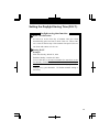
Setting the Daylight Saving Time (D.S.T.)
Daylight saving time function
1 D.S.T. execution time
At 2:00 a.m. on the first day of summer time, the clock
automatically gains one hour to show 3:00 a.m. When 3:00
a.m. comes on the last day of the summer time period, it loses
one hour and returns to 2:00 a.m.
2 Setting D.S.T.
Example:
Start date Sunday, March 25, 2001
End date Sunday, October 28, 2001
If set as the above, the unit remembers the start date as th e
last Sunday of March and the end date as the last Sunday of
October. Once set, the unit automatically updates the
settings every year thereafter. No further manual setting is
necessary.
15
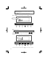
• Daylight saving time is not pre-set at the factory (with the indication
of month 00 and day 00).
• The D.S.T. button stays lit up during its setting operation.
1 Press SELECT to cause the fourth button from the left, D.S.T. , to light up.
12Hr.
Start date of D.S.T.
SU
MO
TU
WE
TH
FR
SA
1/60
1/100
YEAR MONTH
RED/BLK. EX.ALM
PAY ENDING
DATE/TIME
DAY
COL.
HOUR
DAY ADV.TIME
MINUTE
D.S.T
SECOND/CARD
PROGRAM
EXT.ALARM
SELECT
SET
2 Setting the start date
"01" is indicated at the upper left of the display during setting of the start date.
(1) Press
or
to cause digits to flash, and then press
or
to select the
desired time.
Example: If your D.S.T. starts on March 25, 2001, adjust the digits to "01-03-25".
12Hr.
SU
MO
TU
WE
TH
FR
SA
1/60
1/100
YEAR MONTH
RED/BLK. EX.ALM
PAY ENDING
SELECT
DATE/TIME
DAY
COL.
DAY ADV.TIME
HOUR
MINUTE
D.S.T
SECOND/CARD
PROGRAM
EXT.ALARM
SET
(2) Check the settings on the display and press SET . Now the setting is completed.
16
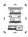
3 Setting the end date
When the start date setting is completed, the indication at the upper left
automatically shifts to "02". You are now in the end date setting mode.
12Hr.
End date of
D.S.T.
SU
MO
TU
WE
TH
FR
SA
1/60
1/100
YEAR MONTH
RED/BLK. EX.ALM
PAY ENDING
DATE/TIME
DAY
COL.
HOUR
DAY ADV.TIME
MINUTE
D.S.T
SECOND/CARD
PROGRAM
EXT.ALARM
SELECT
SET
(1) Press
or
to cause digits to flash, and then press
or
to select the
desired time.
Example: If D.S.T ends on October 28, 2001, adjust the digits to "01-10-28".
12Hr.
SU
MO
TU
WE
TH
FR
SA
1/60
1/100
YEAR MONTH
RED/BLK. EX.ALM
PAY ENDING
DATE/TIME
DAY
COL.
DAY ADV.TIME
SELECT
HOUR
MINUTE
D.S.T
SECOND/CARD
PROGRAM
EXT.ALARM
SET
(2) Check the settings on the display and press SET . Now the setting is completed.
How to Cancel D.S.T. Settings
12Hr.
SU
MO TU
WE
TH
FR
SA
1/60
1/100
YEAR MONTH
RED/BLK. EX.ALM
PAY ENDING
SELECT
DATE/TIME
DAY
COL.
HOUR
DAY ADV.TIME
MINUTE
D.S.T
SECOND/CARD
PROGRAM
EXT.ALARM
SET
Place the unit to the D.S.T. start date
setting mode as described above
(1) and press
or
to cause
month digits to flash.Then select
"00" and press SET to disable the
D.S.T. function.
17
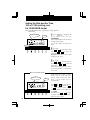
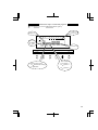
Setting the Time Table Program
The time table program function allows automatic selection of print color (black or red),
an external time signal, and automatic selection of a column to print records in. These
functions can be set by the day of the week and time period.
• No time table program is factory-set. (The default is: print in black; no external time
signal; and print in Column 1.)
• The PROGRAM button stays lit up during its setting operation.
The time table program is explained using the following example.
Day advance time:
05:00
Sunday
Next day
05:00
12:00
Print in red/in Column 5
Print in red/in Column 6
"P-01"
Day advance time:
05:00
Monday - Saturday
"P-02"
09:00
Print in black/
in Column 1
12:00
17:30
Next day
05:00
Print in red/
in Column 2
Print in red/
in Column 3
Print in black/
in Column 4
"P-03"
"P-04"
"P-05"
Signal
Signal
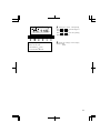
The following is the time table based on the case above.
Program No. Day of week
18
Time
Print color
External time
Print column
signal
P-01
Sun.
05:00
Red
5
P-02
Sun.
12:00
Red
6
P-03
Mon. - Sat.
09:00
Red
2
P-04
Mon. - Sat.
12:00
Red
3
P-05
Mon. - Sat.
17:30
Black
4
are always printed in black in Column 1 for the time period with no program setting.
• Times
programmed day begins at the day advance time.
• One
See "Setting Day Advance Time" in this section for details.
• Up to 32 programs can be set (P-01 through P-32).
Follow these steps to set time table programs.
1 Press SELECT to cause the PROGRAM button light up.
Day of the week
to be set
Program No.
12Hr.
SU
MO
TU
WE
TH
FR
SA
1/60
Print color
00 Black
01 Red
1/100
YEAR MONTH
RED/BLK. EX.ALM
PAY ENDING
DATE/TIME
SELECT
External time signal
00 Disabled (no setting)
01 Enabled
DAY
COL.
DAY ADV.TIME
HOUR
MINUTE
D.S.T
SECOND/CARD
PROGRAM
Time to be set
EXT.ALARM
SET
Print column
01 Column 1
02 Column
2
.
.
.
06 Column 6
19
P-01
Print in red
12Hr.
SU
MO TU
WE
TH
FR
2
SA
1/60
1/100
YEAR MONTH
RED/BLK. EX.ALM
PAY ENDING
DATE/TIME
DAY
COL.
HOUR
DAY ADV.TIME
MINUTE
D.S.T
SECOND/CARD
PROGRAM
EXT.ALARM
SELECT
SET
12Hr.
SU
MO TU
WE
TH
FR
SA
1/60
1/100
YEAR MONTH
RED/BLK. EX.ALM
PAY ENDING
DATE/TIME
DAY
COL.
HOUR
DAY ADV.TIME
MINUTE
D.S.T
SECOND/CARD
PROGRAM
EXT.ALARM
SELECT
SET
To set P-01 (shown in the table
above)
(1) Print color
With "P-01" flashing, press
once.
The print color indication flashes at the
lower left of the display.
"00"
represents "print in black."
Press
and change the digits to "01"
to be set at "print in red."
(2)External time signal
Press
once. The external time
signal indication flashe s. "00"
represents "disabled (no setting) ."
Leave the digits as they are since no
setting is necessary for the P-01
program.
To enable an external time signal,
select "01".
Print in
column 5
12Hr.
SU
MO TU
WE
TH
FR
SA
1/60
1/100
YEAR MONTH
RED/BLK. EX.ALM
PAY ENDING
DATE/TIME
DAY
COL.
HOUR
DAY ADV.TIME
MINUTE
D.S.T
SECOND/CARD
PROGRAM
EXT.ALARM
SELECT
SET
05:00
12Hr.
SU
MO TU
WE
TH
FR
(4)Time
Press
the hour indication flashes.
Press
to change the digits to "05"
to set "05:00".
SA
1/60
1/100
YEAR MONTH
RED/BLK. EX.ALM
PAY ENDING
SELECT
20
DATE/TIME
DAY
COL.
DAY ADV.TIME
HOUR
MINUTE
D.S.T
SECOND/CARD
PROGRAM
(3)Print column
Press
once. The print column
indication flashes. "01" represents
"Column 1".
Press
and change the digits to "05"
to set "print in Column 5".
EXT.ALARM
SET
00 minute
12Hr.
SU
MO TU
WE
TH
FR
SA
Press
again. The minute indication
flashes.
Leave the digits as they are since the
desired time is 05:00 in this case.
1/60
1/100
YEAR MONTH
RED/BLK. EX.ALM
PAY ENDING
DATE/TIME
DAY
COL.
HOUR
DAY ADV.TIME
MINUTE
D.S.T
SECOND/CARD
PROGRAM
EXT.ALARM
SELECT
SET
12Hr.
SU
MO TU
WE
TH
FR
(5)Day of the week
Press
. The bar under "SU" flashes
("-").
SA
1/60
1/100
YEAR MONTH
RED/BLK. EX.ALM
PAY ENDING
DATE/TIME
DAY
COL.
HOUR
DAY ADV.TIME
MINUTE
D.S.T
SECOND/CARD
PROGRAM
EXT.ALARM
SELECT
SET
Erase "-"
under MO.
12Hrt.
SU
MO TU
WE
TH
FR
SA
1/60
1/100
YEAR MONTH
RED/BLK. EX.ALM
PAY ENDING
DATE/TIME
DAY
COL.
HOUR
DAY ADV.TIME
MINUTE
D.S.T
SECOND/CARD
PROGRAM
EXT.ALARM
SELECT
SET
The factory setting for a day of the
week is all days from Sunday
through Saturday. If only Sunday
needs to be selected, the bars under
Monday through Saturday have to be
cancelled.
For the P-01 program, to select Sunday
only.
First, press
to cause the bar under
"MO" to flash, and press
once to
erase the bar ("-").
At that time, the bar under "TU" is
already flashing automatically.
Press
again to erase the bar ("-").
Erase "-"
under TU.
12Hr.
SU
MO TU
WE
TH
FR
SA
1/60
1/100
YEAR MONTH
RED/BLK. EX.ALM
PAY ENDING
SELECT
DATE/TIME
DAY
COL.
DAY ADV.TIME
HOUR
MINUTE
D.S.T
SECOND/CARD
PROGRAM
EXT.ALARM
SET
21
Erase "-"
under MO - SA.
12Hr.
SU
MO TU
WE
TH
FR
SA
1/60
1/100
YEAR MONTH
RED/BLK. EX.ALM
PAY ENDING
DATE/TIME
DAY
COL.
HOUR
DAY ADV.TIME
MINUTE
D.S.T
SECOND/CARD
PROGRAM
EXT.ALARM
SELECT
SET
12Hr.
SU
MO TU
WE
TH
FR
The P-01 indication stays lit up
completing the P-01 program setting.
SA
1/60
Staying lit up
Take the same steps described above
to erase the bars for the remaining days
of the week.
After erasing the bar under "SA", press
SET .
1/100
YEAR MONTH
RED/BLK. EX.ALM
PAY ENDING
DAY
COL.
HOUR
DATE/TIME DAY ADV.TIME
MINUTE
D.S.T
SECOND/CARD
PROGRAM
EXT.ALARM
SELECT
SET
P-02
3 To set P-02
Flashing
12Hr.
SU
MO TU
WE
TH
FR
SA
1/60
1/100
YEAR MONTH
RED/BLK. EX.ALM
PAY ENDING
DATE/TIME
DAY
COL.
HOUR
DAY ADV.TIME
MINUTE
D.S.T
SECOND/CARD
PROGRAM
EXT.ALARM
SELECT
SET
Staying lit up
12Hr.
SU
MO TU
WE
TH
FR
SA
1/60
1/100
YEAR MONTH
RED/BLK. EX.ALM
PAY ENDING
SELECT
Make sure the bar under any day of
the week stays lit up. If the bar
does not stay lit up, the time table
program will not operate properly.
DATE/TIME
DAY
COL.
DAY ADV.TIME
HOUR
MINUTE
D.S.T
SECOND/CARD
PROGRAM
EXT.ALARM
SET
After the setting of P-01 is completed,
press
. The program NO., the
indication at the upper left "P-01",
flashes. Then press
to enter "P02" setting mode.
The program NO. indication "P-02"
flashes.
Make settings for P-02 in the same
manner as for P-01, as illustrated in the
figures at the left.
Press SET .
The P-02 indication now stays lit up,
showing completion of the P-02
program setting.
Likewise, to shift to P-03, press
to
cause the P-03 indication to appear
flashing.
22
P-03
12Hr.
External
time signal
4 To set P-03
Make the bars
under MO-SA
light up
SU
MO TU
WE
TH
FR
Make settings as shown in the figure at
left, and press SET .
SA
1/60
1/100
YEAR MONTH
RED/BLK. EX.ALM
PAY ENDING
DATE/TIME
DAY
COL.
HOUR
DAY ADV.TIME
MINUTE
D.S.T
SECOND/CARD
PROGRAM
EXT.ALARM
SELECT
SET
P-04
5 To set P-04
12Hr.
SU
MO TU
WE
TH
FR
Make settings as shown in the figure at
left, and press SET .
SA
1/60
1/100
YEAR MONTH
RED/BLK. EX.ALM
PAY ENDING
DATE/TIME
DAY
COL.
HOUR
DAY ADV.TIME
MINUTE
D.S.T
SECOND/CARD
PROGRAM
EXT.ALARM
SELECT
SET
6 To set P-05
P-05
12Hr.
SU
MO TU
WE
TH
FR
Make settings as shown in the figure at
left, and press SET .
Now the setting of the programs in the
table are all complete.
SA
1/60
Print in black1/100
YEAR MONTH
RED/BLK. EX.ALM
PAY ENDING
SELECT
DATE/TIME
DAY
COL.
DAY ADV.TIME
HOUR
MINUTE
D.S.T
SECOND/CARD
PROGRAM
EXT.ALARM
SET
23
To check program settings
Press SELECT to cause PROGRAM to light up. Make the desired program No.
flash. To see program settings, press
.
The
button switches among programs in order starting from P-01. Program
contents are shown on the display in order starting from Sunday and the line feed
time.
To modify program settings
Press SELECT to cause PROGRAM to light up. Make the desired program No. flash.
Press
,
,
, or
to change the settings in the same manner as in its
initial setting.
To erase program settings
Press SELECT to cause PROGRAM to light up. Make the desired program No.
flash. The
button switches among programs in order starting from P-01. Select
the desired program No.
To erase it, set the print column indication at "00" and press SET .
Example:
To erase P-04, set the print column indication at
"00" and press SET as shown in the figure at left.
12Hr.
SU
MO
TU
WE
TH
FR
SA
1/60
1/100
Set the print column YEAR
indication at "00". RED/BLK.
PAY ENDING
MONTH
EX.ALM
DATE/TIME
DAY
COL.
HOUR
DAY ADV.TIME
SELECT
Follow the same procedure described above
to make settings for the desired program.
24
MINUTE
D.S.T
SECOND/CARD
PROGRAM
EXT.ALARM
SET
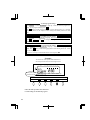
Setting Number of Seconds for External Time Signal
This function sets the duration of the external time signal. The setting is enabled only
when external time signal is set in the time table program.
• The duration is factory-set at 5 seconds.
• The EXT. ALARM button stays lit up during its setting operation.
1/60
1 Press SELECT to cause
1/100
EXT. ALARM to light up.
12Hr.
YEAR
RED/BLK.
PAY ENDING
SU
MONTH
EX.ALM
DATE/TIME
MO TU
DAY
COL.
WE
HOUR
DAY ADV.TIME
TH
FR
MINUTE
D.S.T
SA
SECOND/CARD
PROGRAM
EXT.ALARM
SELECT
SET
12Hr.
SU
MO TU
WE
TH
FR
2 Pres s
or
to adjust th e
duration in seconds.
Example: To set for 30 seconds, set the
second indication at "30".
SA
1/60
1/100
YEAR MONTH
RED/BLK. EX.ALM
PAY ENDING
SELECT
DATE/TIME
DAY
COL.
DAY ADV.TIME
HOUR
MINUTE
D.S.T
SECOND/CARD
PROGRAM
EXT.ALARM
SET
For the number of seconds, 1
through 30 can be selected
3
Check the settings on the display
and press SET .
25
Resetting
To restore all the settings to factory-shipped state, push the reset switch with a pointed
object.
Reset switch
Be careful! Resetting will erase all the settings made by users.
For setting, see "5 Setting".
26
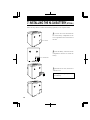
6. CONNECTING TO AN EXTERNAL TIME SIGNAL
Follow the steps below to connect to an external time signal device.
1
Unscrew the screw fixed on the
bottom of the unit to remove the
lid.
Screw
Lid
2 Insert two wires for an external time
signal while pushing the upper part of
the terminal board with a screwdriver.
3
Replace the lid after pulling the
wires through the U-shaped cut
provided on the lid.
Connection Specifications for
External Contact
• Contact output: One circuit, dry
contact
• Contact capacity: 5A, 30VDC
(Resistive)
27
7. INSTALLING THE Ni-Cd BATTERY (OPTIONAL)
Follow the steps below to install a Ni-Cd battery (optional) in case of power failure.
1
Unscrew the screw that holds the
lid of the battery compartment in the
lower right-hand corner of the back of
the unit.
Screw
2
Insert the battery connector into the
compartment connector to install the
battery.
Connector
3 Hook the lid to close, and secure it
with the screw.
Use only the originally offered
Ni-Cd Battery.
28
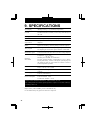
9. SPECIFICATIONS
Clock display
Monthly accuracy ± 15s (at ordinary temperature)
Calendar
Year up to 2096. Automatically adjusted to leap years, 31-day
months and months with thirty or fewer days, and the days of
the week.
Printing system
Dot matrix in black and red
Card mechanism
Automatic pull and eject, automatic judgment of face and back
Power failure
compensation
Five years of cumulative power failure hours after the date of
shipment
Print at power
failure
Special Ni-Cd battery, 100-time printing or 24 hours (option)
Time program
Switching between black and red printing, designation of the time
for outputting an external time signal, automatic column shift.
Connection of
external time signal
Connection with a time flow device (No direct voltage output!)
Operating
environment
Temperature: -5° to + 45°C
: + 23° to + 113°F
Humidity: 20 to 80%RH, no condensation
The unit operates normally at temperatures of 5°C or below,
but the print density, reaction of the liquid crystal display, and
the number of prints at power failure are inferior to those at
normal temperature operation.
Dimensions
7.87" (w) x 10.1" (h) x 5.94" (d)
200 (w) x 257 (h) x 151 (d) mm
Weight
Approx. 5.5lbs 2.5kg
Power supply
120VAC
230VAC (220-240VAC)
Power consumption
120VAC 50/60Hz 0.2A
230VAC 50/60Hz 0.12A
220-240VAC 50/60Hz 0.12A
Machine Noise Information Ordinance 3. GSGV, January 18, 1991:
The sound pressure level at the operator position is equal to or less than 70 dB (A)
according to ISO 7779.
Replace battery with TOSHIBA, part No. CR2450THC only.
Use of another battery may present a risk of fire or explosion.
30
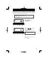
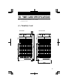
10. TIME CARD SPECIFICATIONS
Note : Recommended paper thickness : 0.45 ± 0.05mm
Note : Card style may vary.
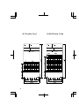
(1) Monthly Card
Front Side
Reverse Side
1
2
31
(2) Weekly Card
32
(3) Bi-Weekly Card
Printed in Japan
1406-9806
10-10B01S