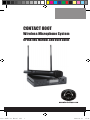
1
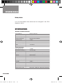
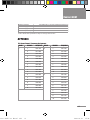
ontact 800T User Manual.indd
CONTACT 800T
Wireless Microphone System
OPERATING MANUAL AND USER GUIDE
www.wharfedalepro.com
1
2010-10-21
17:34:
ontact 800T User Manual.indd
1
2010-10-21
17:34:
Contact 800T
IMPORTANT WARNINGS & SAFETY INSTRUCTIONS
1.
2.
3.
4.
5.
6.
7.
8.
9.
10.
11.
12.
ontact 800T User Manual.indd
Please read and retain these safety instructions.
Heed all warnings in the operating instructions and on the
appliance.
Do not use this apparatus near water or moisture.
Clean only with a dry cloth. Do not install near sources of heat such as radiators, heat
registers, stoves or other apparatus that produce heat.
Refer all servicing to authorised personnel.
There are no user serviceable parts inside this product.
Users should not attempt to service this product. Warranty
nullification could result if this is attempted.
Servicing is required when the apparatus has been damaged
in any way including: Impact damage, power cord/supply
damage, liquid spillages, small objects falling into the unit or
exposure to moisture. In addition please refer to authorised
service personnel if the apparatus is not operating normally.
To completely disconnect this equipment from the AC mains
disconnect the power plug from the AC receptacle.
To prevent fire never place the unit near any naked flame
such as a candle.
Do not defeat the purpose of the polarized or grounding type
plug. A polarized plug has two blades with one wider than
the other. A grounding type plug has two blades and a third
grounding prong. The wide blade or the third prong are there
for your safety. If the plug does not fit into your outlet, consult
an electrician for replacement of the obsolete outlet.
USING AMPLIFIERS – In order to avoid damage to drivers
and other equipment, it is advisable to establish and follow a
routine for powering up and powering down a sound system.
With all system components connected, turn on source
equipment (mixers, signal processors, record and playback
1
2010-10-21
17:34:
OPERATING MANUAL
13.
14.
15.
units, etc.) BEFORE powering up amplifiers. Transient
voltages from powering up source equipment can damage
speakers if amplifiers are already turned on. Make sure that
amplifier volumes are set to their minimum settings and
power up any system amplifiers LAST. It is recommended
that all system components be allowed to stabilize for several
seconds before any source signals are introduced or level
setting adjustments are made. Similarly, when shutting
systems down, turn all amplifiers off first, before powering
down any other system components.
CABLES – Do not use shielded or microphone cables for
connection between amplifiers and speakers. Use only
approved speaker cables with proper connectors.
R I G G I N G – SU S PEN D I N G – M O U N TI N G – R i g ging,
suspending and mounting of speaker systems can expose
members of the public to serious health risks and even
death. U N D ER N O CIRCU M STA N CES AT TEM PT TO
RIG, SUSPEN D O R OTH ERWISE M OU NT SOU N D
REINFORCEMENT PRODUCTS UNLESS YOU ARE FULLY
QUALIFIED AND CERTIFIED TO DO SO BY RELEVANT
L O C A L , S TAT E A N D N AT I O N A L A U T H O R I T I E S .
A L L R ELE VA N T S A FE T Y R EG U L ATI O N S M U ST B E
FOLLOWED. IF YOU ARE NOT PROPERLY QUALIFIED
OR DO NOT KNOW OF PERTINENT REGUL ATIONS,
CONSULT QUALIFIED PERSONNEL FOR ADVICE.
CAUTION – Professional sound reinforcement systems
are capable of generating very high sound pressure levels.
Take care with placement and operation to avoid exposure
to excessive volume levels. Permanent hearing damage can
result when operated to extreme levels.
ontact 800T User Manual.indd
2
2010-10-21
17:34:
Contact 800T
TABLE OF CONTENTS
Important Warnings & Safety Instructions.....................................1
Wharfedale Pro Contact 800T Wireless Microphone System......4
Parts Names And Functions..........................................................4
Transmitter / Microphone................................................................6
Installation Of The Receiver . ........................................................7
Audio Output Connections.............................................................8
Receiver Settings...........................................................................9
LCD Display Legend.....................................................................10
Function Descriptions................................................................... 11
Specifications ..............................................................................12
Appendix ......................................................................................13
Wharfedale Pro Limited Warranty................................................ 17
ontact 800T User Manual.indd
3
2010-10-21
17:34:
OPERATING MANUAL
WHARFEDALE PRO CONTACT 800T WIRELESS
MICROPHONE SYSTEM
Thank you for selecting the Wharfedale Pro Contact 800T
single channel wireless microphone system.
Before operating the system, please take time to read this
instruction manual thoroughly for a complete understanding of
the product features and correct operating procedures. This
will ensure that you get the most from your Wharfedale Pro
Contact 800T.
System inventory
(1) Injection moulded carrying case
(1) Contact 800T True Diversity Receiver
(1) Contact 800T Wireless Transmitter / Microphone
(2) Screw on antenna assemblies
(1) Power supply / power cord
(2) AA batteries
(1) Unbalanced line cable with ¼” plugs
(1) Rack Mount Adapter
(1) User manual (1) Warranty Registration card
PARTS NAMES AND FUNCTIONS
1. POWER switch 2. SYNC button: Synchronisation of transmitter & receiver
(Automatic Channel Matching)
3. MENU button: Multiple function selection.
4. SYNC I/R receiver: Works with the microphone transmitter SYNC signal ontact 800T User Manual.indd
4
2010-10-21
17:34:
Contact 800T
5. LCD Display: Shows the currently selected function 6. Group Select button: Changes the group setting parameter
7. Channel Select button: Changes the channel setting
parameter
8. VOLUME Control: Adjusts the output volume level
Contact 800T
9. ANTENNA B connector
10. Output ‘LEVEL’ Switch: Use the “MIC” setting when the output is connected to a microphone input. Use the “LINE”
setting when the output is Contact
connected
to a line level input. 800T
11. BALANCED OUTPUT XLR connector 12. UNBALANCED OUTPUT ¼” jack
13. DC INPUT 12V power input jack
14. ANTENNA A Connector
ontact 800T User Manual.indd
Contact 800T
Contact 800T
5
2010-10-21
17:34:
Contact 800T
OPERATING MANUAL
Contact 800T
TRANSMITTER / MICROPHONE (FIG.3)
Contact 800T
(Fig.3)
Install the provided “AA” batteries in the microphone battery
compartment (Fig.4 / 5) by holding the main barrel of the
microphone firmly while turning to unscrew the transmitter
section (the portion with the LCD display) and slide it open to
reveal the battery compartment in the middle section of the
mic.
Once the batteries are installed and the battery compartment
is closed and tightened, switch the microphone ON (the “1”
setting on the small switch at the end of the microphone
barrel) to verify correct installation. The red LED on the mic
should illuminate and the LCD display on the mic will become
active. Contact 800T
Turn the microphone off (the ‘0’ switch setting at the end of the
microphone barrel) before proceeding.
Contact 800T
(Fig.4,5)
ontact 800T User Manual.indd
6
2010-10-21
17:34:
Contact 800T
Contact 800T
Contact 800T
INSTALLATION OF THE RECEIVER
Connect the antennas into ANTENNA A connector and
ANTENNA B connector at the rear of the Contact 800T
Receiver as shown below. (Fig 6/A). Rotate and flip the
antennas to the upward position as shown in FIG.6-B.
Contact 800T
(Fig.6A)
Contact 800T
(Fig.6B)
Connecting the power:
Connect the AC/DC adapter cable to the DC INPUT 12V
socket as shown in Fig.7. Connect the other end of the cord
to the AC outlet. (Caution: The specification of the adapter
should be compatible with the voltage specification for the
local power source voltage.)
ontact 800T User Manual.indd
(Fig.7)
7
2010-10-21
17:34:
OPERATING MANUAL
AUDIO OUTPUT CONNECTIONS
Select the ‘LINE’ position of the ‘LEVEL’ switch when the
output of the receiver is connected to the line level input of
a mixer or amplifier. Select the ‘MIC’ position of the ‘LEVEL’
switch when the output of the receiver is connected to a
microphone level input of a mixer. Distortion may occur if the
‘LEVEL’ switch is set to the wrong position. (Fig.8)
The ‘BALANCED OUTPUT’ should be used when the receiver
is going to be connected to either a microphone or line level,
balanced input of a mixer. (Fig.9)
Longer runs are less likely to cause problems with balanced
cables.
The ‘UNBALANCED OUTPUT’ should be used when the
receiver is going to be connected to a ¼” input jack of a mixer
or an amplifier (usually line level) that uses a ¼” jack. Use the
appropriate setting on the ‘LEVEL’ switch on the rear panel
of the Contact 800T. Cable length for this type of connection
should be limited to less than 15 feet (5 meters). (Fig.10)
(Fig.10)
(Fig.9)
(Fig.8)
ontact 800T User Manual.indd
8
2010-10-21
17:34:
Contact 800T
RECEIVER SETTINGS
Verify that the ‘VOLUME’ control setting is at its minimum (fully
counterclockwise).
With the microphone still turned OFF, Press and hold the
‘POWER’ button on the front panel of the receiver until the
LED display lights up.
Once the display is fully illuminated, press the ‘MENU’ button,
repeatedly, until the “G/CH” icon is highlighted. The display will
read the currently selected “GROUP” number and “CHANNEL”
number. These settings can be changed with the UP/DOWN
buttons. It is not necessary to change these settings in order
for the system to work, but they can be changed if any signal
interference is experienced. See the Appendix for Group /
Channel / Frequency assignments.
To change the ”GROUP” setting, press the “up” button (next
to the ‘VOLUME’ knob) repeatedly until the desired “GROUP”
number is displayed. There are 9 Groups available.
To change the ”CHANNEL” setting, press the “down” button
(next to the VOLUME knob) repeatedly until the desired
“CHANNEL” number is displayed. See the Appendix for
Group/Channel correlations.
Once these settings are made, turn the microphone on and
press the ‘SYNC’ button and the receiver will automatically
synchronize with the microphone transmitter at the selected
Group/Channel frequency assignment. The synchronization
is successful when the “RF” level meter shows a signal
indication. The “AF” meter will respond to any sounds being
picked up by the microphone. Speaking into the mic should
show significant audio level indications on the “AF” meter.
Other indications on the receiver’s display will also indicate
“TX” (transmit) and one of the “A” or “B” antenna indicators will
ontact 800T User Manual.indd
9
2010-10-21
17:34:
OPERATING MANUAL
be highlighted showing which antenna has been automatically
selected for the strongest reception.
In accordance with the operating instructions of your mixer or
output device, adjust the gain controls and gradually increase
the ‘VOLUME’ knob on the Contact 800T receiver to achieve a
suitable level setting of the microphone signal.
LOCK / UNLOCK function:
Holding the ‘MENU’ button down for more than 3 seconds will
result in the word “LOCK” being displayed on the LCD panel.
This function stores the unit’s settings at the currently selected
configuration. When the unit is in “LOCK” mode holding the
‘MENU’ button for 3 seconds will toggle the function back to
the “UNLOCK” mode and parameters can be changed.
LCD DISPLAY LEGEND
Display Modes:
Pressing the ‘MENU’ button repeatedly will change the
information displayed in the alpha- numeric section of the LCD
panel showing the five display modes available:
-GROUP/CH
-FREQ (Frequency) -SQ (Squelch) -VOL (Mute)
-NAME (Name) will be highlighted in the display with each
press of the ‘MENU’ button
10
ontact 800T User Manual.indd
10
2010-10-21
17:34:
Contact 800T
FUNCTION DESCRIPTIONS
G/CH – Group / Channel:
This allows for the selection of the Group and the Channel
assignment to match the wireless microphone transmitter
being used with the receiver. 9 Groups and 4 Channel
selections are available. The Up button selects the Groups,
the Down button selects the Channel
FREQ – Frequency:
This displays the automatically selected frequency. SQ – Squelch:
This adjusts the level of “squelch” (0-99) which can minimize
transmission/reception noise bet ween the microphone
transmitter and the receiver. Level is selected with the Up/
Down button.
VOL – Volume:
This mutes and un-mutes the output of the audio from the
receiver when either the Up or Down button is depressed
NAME – Name:
This allows for the custom naming of the microphone and
receiver for easy identification. Use the Up/Down buttons to
select an alphanumeric character. Press the ‘MENU’ button to
scroll through the 6 available characters. The name will be set
after the sixth character is entered and the ‘MENU’ button is
pressed.
LOCK – This function locks system settings and the following
icon is displayed when active: (To unlock, hold the “MENU” button for 3 seconds)
ontact 800T User Manual.indd
11
11
2010-10-21
17:34:
OPERATING MANUAL
Battery status
It is recommended that batteries be changed if the 25%
display is active.
SPECIFICATIONS
Microphone / Transmitter Specifications
Housing Material
Oscillation Mode
Aluminum Extrusion
PLL Synthesized
Carrier Frequency Range
UHF 529-865MHz
Stability
±0.005%(-10/50 I I)
Frequency Adjustment
Automatic Channel Setting
RF Output Power
>10mW
Spurious Emissions
<-55dBc
Max. Deviation Range
±68KHz
Maximum Input Level
140dB SPL
Battery
1.5V (AA)×2
Receiver Specifications
12
ontact 800T User Manual.indd
Signal to Noise Ratio
>105dBA
Total Harmonic Distortion
<0.5% at 1KHz
Frequency Response
50Hz~18KHz ±3dB
Functional Distance
>100meters (Open area distance)
Main Frame Size
EIA standard 1/2-rack unit
Channels
Single-channel
Receiver Module
True Diversity
Oscillation Mode
PLL synthesized
Carrier Frequency Range
UHF 529-865MHz
Stability
±0.005%(-10-50 OC)
Bandwidth
13 MHz
Sensitivity
2μV (S/N>12dB 25KHz deviation )
Frequency Interval
250KHz
Available Frequencies
50
Squelch Innovative
PiloTone & NoiseLock dual-squelch circuit
Maximum Output Level
MIC LEVEL-14dBV/100Ω, LINE LEVEL-4dBV/5KΩ
Output Connectors
XLR balanced & ¼”/6.3mm unbalanced phone jack.
AC Power Supply
External 90-260VAC
DC Power Supply
1A, 12-15VDC
Dimensions: (HxWxD)
1.7”x8.6”x6.3” / 44mm×220mm×160mm
Product details and specifications subject to change without notice.
12
2010-10-21
17:34:
Frequency Response
50Hz~18KHz ±3dB
Functional Distance
>100meters (Open area distance)
Main Frame Size
EIA standard 1/2-rack unit
Channels
Single-channel
Receiver Module
True Diversity
Oscillation Mode
PLL synthesized
Carrier Frequency Range
UHF 529-865MHz
Stability
±0.005%(-10-50 OC)
Bandwidth
13 MHz
Sensitivity
2μV (S/N>12dB 25KHz deviation )
Frequency Interval
250KHz
Available Frequencies
50
Squelch Innovative
PiloTone & NoiseLock dual-squelch circuit
Maximum Output Level
MIC LEVEL-14dBV/100Ω, LINE LEVEL-4dBV/5KΩ
Output Connectors
XLR balanced & ¼”/6.3mm unbalanced phone jack.
Contact 800T
AC Power Supply
External 90-260VAC
DC Power Supply
1A, 12-15VDC
Dimensions: (HxWxD)
1.7”x8.6”x6.3” / 44mm×220mm×160mm
Product details and specifications subject to change without notice.
APPENDIX
F07 Group Chann
F06 Group Channel / Frequency Assignments
GROUP
CHANNEL
FREQUENCY
GROUP
CHANNEL
FREQUENCY
GROUP
CH
1
1
740.125
3
1
740.125
1
1
2
741.500
2
741.225
2
3
743.375
3
742.925
3
4
744.600
4
744.325
5
746.325
5
745.425
6
748.500
6
746.875
2
7
750.050
7
748.925
3
8
751.875
8
750.175
1
740.125
9
751.200
2
741.950
3
743.500
4
2
4
2
1
4
3
1
10
751.875
2
1
740.125
3
745.675
2
740.800
5
747.400
3
741.825
6
748.625
4
743.075
2
7
750.500
5
745.125
3
8
751.875
6
746.675
7
747.675
8
749.075
2
9
750.775
3
10
751.875
4
4
4
4
1
4
5
1
5
6
13
7
8
F08 Group Channel / Frequency Assignments
GROUP
ontact 800T User Manual.indd
1
CHANNEL
13 1
FREQUENCY
GROUP
CHANNEL
FREQUENCY
793.275
6
1
793.725
2010-10-21
17:34:
OPERATING MANUAL
F07 Group Channel / Frequency Assignments
FREQUENCY
GROUP
CHANNEL
FREQUENCY
GROUP
CHANNEL
FREQUENCY
740.125
1
1
780.275
6
1
780.725
741.225
2
781.075
2
781.250
742.925
3
787.400
3
782.225
744.325
4
792.225
4
782.650
1
780.525
5
785.350
746.875
2
781.325
6
785.875
748.925
3
787.650
7
786.925
750.175
4
792.475
8
787.375
1
780.775
1
783.400
2
745.425
3
751.200
7
751.875
2
781.575
2
785.000
740.125
3
787.900
3
786.175
740.800
4
792.725
4
787.950
1
781.025
5
788.425
743.075
2
781.825
6
789.500
745.125
3
788.150
7
790.225
746.675
4
792.975
8
791.275
1
780.525
1
783.525
749.075
2
781.050
2
785.125
750.775
3
782.025
3
786.300
751.875
4
782.450
4
788.075
5
785.150
5
788.550
6
785.675
6
789.625
7
786.725
7
790.350
8
787.175
8
791.400
1
783.000
2
791.000
4
741.825
5
747.675
8
9
FREQUENCY
793.725
F10 Group Channel / Frequency Assignments
794.250
795.225
795.650
14
GROUP
CHANNEL
FREQUENCY
1
1
863.100
2
863.300
3
863.500
4
863.700
5
863.900
798.350
798.875
799.925
ontact 800T User Manual.indd
14
GROUP
CHANNEL
FREQUENCY
2010-10-21
17:34:
8
751.875
4
6
746.675
7
747.675
8
749.075
2
9
750.775
3
10
751.875
4
5
1
5
6
Contact 800T
7
8
F08 Group Channel / Frequency Assignments
GROUP
1
2
3
4
5
ontact 800T User Manual.indd
CHANNEL
FREQUENCY
GROUP
CHANNEL
FREQUENCY
1
793.275
6
1
793.725
2
794.075
2
794.250
3
800.400
3
795.225
4
805.225
4
795.650
1
793.525
5
798.350
2
794.325
6
798.875
3
800.650
7
799.925
4
805.475
1
793.775
8
800.375
1
796.400
2
794.575
2
798.000
3
800.900
3
799.175
4
805.725
4
800.950
1
794.025
5
801.425
2
794.825
6
802.500
3
801.150
7
803.225
4
805.975
8
804.275
1
793.525
1
796.525
2
794.050
2
798.125
3
795.025
3
799.300
4
795.450
4
801.075
5
798.150
5
801.550
6
798.675
6
802.625
7
799.725
7
803.350
8
800.175
8
804.400
1
796.000
2
804.000
7
8
9
F10 Group Channe
GROUP
CHA
1
1
2
3
4
5
6
7
8
9
10
15
15
2010-10-21
17:34:
EL
750.775
3
782.025
3
786.300
751.875
4
782.450
4
788.075
5
785.150
5
788.550
6
785.675
6
789.625
7
786.725
7
790.350
8
787.175
8
791.400
1
783.000
2
791.000
OPERATING MANUAL
9
FREQUENCY
793.725
F10 Group Channel / Frequency Assignments
794.250
795.225
795.650
GROUP
CHANNEL
FREQUENCY
1
1
863.100
2
863.300
3
863.500
4
863.700
5
863.900
6
864.100
7
864.300
8
864.500
9
864.700
10
864.900
798.350
798.875
799.925
800.375
796.400
798.000
799.175
800.950
801.425
802.500
CONTACT 800T available RF
frequency ranges
803.225
GROUP
CHANNEL
FREQUENCY
F06 Group Channel / Frequency Assignmen
GROUP
CHANNEL
FREQUENCY
GR
1
1
740.125
3
804.275
CODE
Frequency Range
2
741.500
796.525
F01
529 - 542 MHz
3
743.375
798.125
F02
583 - 596 MHz
4
744.600
799.300
F03
649 - 662 MHz
5
746.325
801.075
F04
683 - 696 MHz
6
748.500
750.050
801.550
F05
713 - 726 MHz
7
802.625
F06
740 - 752 MHz
8
751.875
803.350
F07
780 - 793 MHz
1
740.125
804.400
F08
793 - 806 MHz
2
741.950
796.000
F09
828 - 841 MHz
3
743.500
863 - 865 MHz
4
745.675
5
747.400
6
748.625
7
750.500
8
751.875
F10
804.000
2
4
16
ontact 800T User Manual.indd
16
2010-10-21
17:34:
Contact 800T
WHARFEDALE PRO LIMITED WARRANTY
Wharfedale Pro Contact 800T is warranted of manufacturing or
material defects for a period of one year from the original date of
purchase. In the event of malfunction, contact your authorized
Wharfedale Pro dealer or distributor for information.
*Be aware that warranty details may dif fer from countr y to
country. Contact your dealers or distributor for information. These
terms do not infringe your statutory rights.
ontact 800T User Manual.indd
17
17
2010-10-21
17:34:
ontact 800T User Manual.indd
WharfedaleProfessional
IAG House, 13/14 Glebe Road, Huntingdon, Cambridgeshire,
PE29 7DL, UK
www.wharfedalepro.com
WharfedaleProfessionalreservestherighttoalter
or improve speci ications without notice.
Allrightsreserved©200WharfedalePro.
WharfedaleProisamemberoftheIAGGroup.
18
2010-10-21
17:34: