1
I N D O O R C L I M AT E
UPONOR
CONTROL SYSTEM
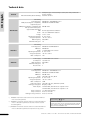
Uponor Control System –
Installation and Operation
Manual
01 | 2009
UK English
Installation and operation manual
Quick start guide ..............................................................3
6
Reset controller .................................................................30
Deregister channels in controller .......................................30
Reset Interface I-75/76 ...................................................30
Preface ...............................................................................6
Copyright and disclaimer ...................................................7
1
Uponor Control System ...............................................9
Controller C-55/56 .............................................................9
Thermostats T-75, T-55, and T-54 Public...........................10
Interface I-75/76 ..............................................................11
Interface with controller kit ...............................................11
Accessories .......................................................................12
2
Install Uponor Control System ..................................13
Prepare for installation ......................................................14
3
Install Uponor Controller C-55/56 ............................15
Install controller antenna ..................................................15
Attach controller to wall....................................................15
Connect components to controller ....................................16
Optional: connect heating/cooling input ..........................16
Optional: connect pump management ..............................17
Connect controller to AC power ........................................17
Test actuators....................................................................18
4
Install Uponor Thermostats.......................................19
Optional: connect Thermostat T-54 Public
to external sensor..............................................................19
Register thermostats in controller .....................................21
Install Thermostat with display T-75 ..................................21
Install Thermostat T-54 Public and T-55 ............................22
Test communication ..........................................................22
Complete controller installation ........................................22
5
Install Uponor Interface I-75/76...............................23
Wire Interface I-75/76 to Controller C-55/56...................23
Optional: connect multiple controllers ..............................24
Use navigation keys ..........................................................25
Set language .....................................................................25
Set time and date..............................................................25
Access Installer level .........................................................26
Optional: set controller IDs ...............................................26
Optional: set pump management ......................................26
Display actuator status......................................................27
Set exercise schedule ........................................................27
Optional: activate cooling management ............................27
Optional: heating/cooling in separate systems
(Controller C-56 only) .......................................................27
Complete Interface I-75/76 installation ............................28
Optional: room by-pass (Interface I-76 only) ....................28
Optional: auto-balance (Interface I-76 only) ....................28
Room check (Interface I-76 only) .....................................28
Supply diagnostics (Interface I-76 only) ...........................29
Optional: comfort setting (Interface I-76 only)....................29
2
Troubleshoot installation ..........................................30
7
Operate Uponor Controller C-55/56 .........................31
Normal controller operation ..............................................31
8
Operate Uponor Thermostats ....................................32
Operate Thermostat with display T-75...............................32
Operate Thermostat T-55 ..................................................33
Operate Thermostat T-54 Public........................................34
9
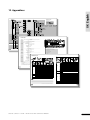
Operate Uponor Interface I-75/76............................36
Use navigation keys ..........................................................36
Interface I-75/76 main screen ..........................................36
Interface I-75/76 main menu............................................36
Access and navigate menu ................................................37
Select access level .............................................................37
Display room information ..................................................37
Display battery and communication status........................37
Display room thermostat status ........................................38
Select heating or cooling mode.........................................38
Use holiday mode .............................................................38
Assign room name ............................................................38
Set minimum/maximum temperatures ..............................39
Disable cooling .................................................................39
Set temperature unit .........................................................39
Set time and date..............................................................39
Use ECO mode ..................................................................40
Exercise functionality of valves and pumps .......................41
Set display backlight .........................................................41
Display software version ...................................................41
10 Identify alarms ...........................................................42
Display alarms ...................................................................42
11 Problems and recommended solutions .....................43
Thermostat with display T-75 alarms/problems.................44
Thermostat T-55 alarms/problems ....................................45
Thermostat T-54 Public alarms/problems..........................45
Controller C-55/56 alarms/problems ................................45
Contact installer ................................................................45
Installer instructions ..........................................................46
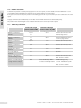
Technical specifications .....................................................46
12 Appendixes.................................................................47
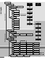
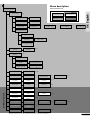
Menu description ..............................................................49
Technical data ...................................................................50
Installation report .............................................................52
U P O N O R C O N T R O L S Y S T E M – I N S TA L L AT I O N A N D O P E R AT I O N M A N U A L
Quick start guide
UK English
Quick start guide
This is a quick start guide to serve as a reminder for experienced installers. We strongly recommend reading the full manual
before installing the Uponor Control System.
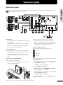
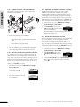
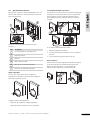
Install antenna
Using the 15 m four-wire connector cable or similar:
•
Connect the antenna to terminals 9 and 10 on the controller
(non-polarized).
•
•
Attach the antenna to a wall or the rear of the controller.
•
If the controller is installed inside a metal cabinet, then
locate the antenna outside the cabinet.
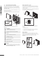
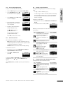
Interface I-75/76 access levels
Uponor Interface I-75/76 has three access levels:
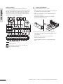
Actuator installation
•
Connect only one actuator for each channel. Channels 01
and 02 have double outputs (a and b) for two actuators.
•
Ensure that each actuator is connected to the correct
channel so that the thermostats are controlling the correct
loops.
Basic
Advanced
Installer
The icons are visible only in Uponor Interface I-76. To go from
Basic to Advanced level:
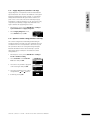
Uponor Interface I-75/76 installation
Using the 2 m RJ-9 connector cable:
•
Connect terminals 1, 2, 3, and 4 on the controller to
terminals 1, 2, 3, and 4 on the Uponor Interface I-75/76.
(Wiring is polarized, so wire 1 on the controller must be
connected to 1 on the interface, and so on.)
Connect the RJ-9 connector on the controller to the RJ-9
connector on Interface I-75/76:
1
On the Uponor screen, simultaneously press
the Advanced display appears.
2
Press OK. The Uponor screen appears.
and
until
To go from Advanced to Installer level:
3
4
1
On the Uponor screen, select Main Menu > Settings >
System Parameters > Access level.
2
On the access level screen, simultaneously press
until the Installer display appears.
3
Press OK. The Uponor screen appears.
3
2
1
4
and
The system will automatically return to Advanced level after
10 minutes of inactivity.
U P O N O R C O N T R O L S Y S T E M – I N S TA L L AT I O N A N D O P E R AT I O N M A N U A L
3
Quick start guide
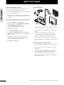
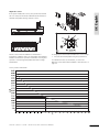
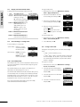
Register thermostats
Optional: install multiple controllers
UK English
Up to three controllers can be interconnected. This is only
possible if an Uponor Interface I-75/76 is used.
1
Connect terminals 5 and 6 on controller 2 to terminals 5 and
6 on controller 1 (polarized).
2
If a third controller is needed, then connect terminals 7 and
8 on controller 3 to terminals 7 and 8 on controller 1 or 2
(polarized).
When connecting multiple controllers, all controllers must have
IDs. To set the controller IDs in Uponor Interface I-75/76:
3
Access the Installer level as described above.
4
On the Uponor screen, select Main Menu > Settings >
System Parameters > Controller ID.
5
Select Reset Controller ID and press OK.
6
Select Yes and press OK.
7
1
Press the Test button on the controller. The test LED comes
on.
Select Set Controller ID and press OK.
2
Press the button of preferred channel. The channel LED
flashes.
8
The message >1. Controller< flashes. Press the Test
button on controller 1 (the controller connected to Uponor
Interface I-75/76).
3
Gently press and hold the registration button on the
thermostat with a pointed instrument until the channel
LEDs are constantly on (can take several seconds).
9
Repeat the operation for controller 2 (the controller
connected to terminals 5 and 6) and controller 3 (the
controller connected to terminals 7 and 8).
4
Repeat steps 2 and 3 until all thermostats are registered.
5
Press the Test button to end registration. The test LED goes
off.
10 Press OK to end identification.
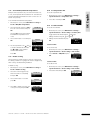
Register thermostat to multiple channels
4
1
Press the Test button on the controller. The test LED comes
on.
2
Press the buttons for the chosen channels. The channel
LEDs flash.
3
Gently press and hold the registration button on the
thermostat with a pointed instrument until the channel
LEDs are constantly on (can take several seconds).
4
When all thermostats are registered, press the Test button.
The test LED goes off.
U P O N O R C O N T R O L S Y S T E M – I N S TA L L AT I O N A N D O P E R AT I O N M A N U A L
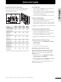
Register thermostat with external sensor
Test communication
Before the thermostat is registered, the configuration switches
on the thermostat must be set according to the way Uponor
Thermostat T-54 will be used:
1
Press and release the Test button on the controller. The
LEDs for all registered channels come on.
2
Press the registration button of each registered thermostat.
If communication is good, then the LEDs for the channels
registered to the thermostat go off.
3
To exit test mode, press the Test button on the controller.
UK English
Quick start guide
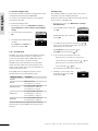
Deregister single thermostats
Switch
1
Switch
2
Switch
3
Switch
4
Used as a standard
room thermostat
Off
Off
Off
Off
Used with a floor
sensor, max.
limitation
On
Off
Off
Off
Used with a floor
sensor, min.
limitation
On
Off
Off
Used with an
outdoor sensor
Off
On
Technical alarm
Off
Used with Uponor
Remote access
module R-56
Off
External (floor)
sensor for room
temperature
Off
Function
1
Press and release the Test button on the controller. The
LEDs for all registered thermostats come on.
2
Press and hold the button of the chosen channel until the
channel LED goes off. The thermostat is now unregistered.
3
Press and release the Test button to exit. The test LED goes
off.
Deregister all thermostats (factory setting)
1
Press and release the Test button on the controller. The
LEDs for all registered thermostats comes on.
2
Press and hold the Test button on the controller until all
channel LEDs go off (can take several seconds).
On
3
Press and release the Test button to exit. The test LED goes
off.
Off
Off
Room by-pass (Uponor Interface I-76 only)
Off
On
Off
1
On the Uponor screen, select Main Menu > Settings >
Rooms > By Pass.
Off
Off
On
2
Choose controller.
3
Choose the room for the by-pass function.
On
Off
On
Auto-balance (Uponor Interface I-76 only)
The auto-balance function removes the need for manual
balancing of the manifold at installation. The auto-balance
function requires an Interface I-76 and is activated with
Installer level access.
1
On the Uponor screen, select Main Menu > Settings >
System Parameters > Auto Balance.
2
On the auto-balance screen, select Active and press OK.
The auto-balance function is now activated.
When Auto-balancing is used, all balancing valves on the
manifold must be fully open.
U P O N O R C O N T R O L S Y S T E M – I N S TA L L AT I O N A N D O P E R AT I O N M A N U A L
5
UK English
Preface
The Uponor Control System Installation and Operation Manual
describes how to install and operate the components of the
system.
Conventions used in this manual
The following symbols are used in the manual to indicate special
precautions when installing the Uponor Control System:
STOP
WARNING
Risk of injury.
STOP
WARNING
The Uponor Control System uses 50 Hz 230 V AC power.
In case of emergency, immediately disconnect the
power.
Limitations for radio transmission
The Uponor Control System uses radio transmission. The
frequency used is reserved for similar applications, and the
chances of interference from other radio sources are very low.
Ignoring warnings can cause injury or damage
components.
However, in some rare cases, it might not be possible to
establish perfect radio communication. The transmission
range is sufficient for most applications, but each building
has different obstacles affecting radio communication and
maximum transmission distance. If communication difficulties
exist, Uponor can support the system with accessories, such as
repeaters, for solving exceptional problems.
CAUTION
Ignoring cautions can cause malfunctions.
Safety measures
Read and follow the instructions in the Installation and
Operation Manual.
Technical constraints
Installation must be performed by a competent person in
accordance with local regulations.
It is prohibited to make changes or modifications not specified
in this manual.
All power supply must be switched off before starting any
wiring work.
• To avoid interference, keep installation/data cables
away from power cables for more than 50 V.
• The electrical circuits of the boiler and the pump
must be protected by a circuit breaker rated at 6 A or
below.
Do not use water to clean Uponor Control System components.
Disposal
Do not expose the Uponor Control System to flammable
vapours or gases.
The Uponor Control System consists of various recyclable
components. Uponor would be grateful if the components
(batteries, plastics, and electric or electronic parts) are sorted
and disposed of at a suitable recycling centre.
We cannot accept any responsibility for damage or breakdown
that can result from ignoring these instructions!
6
Power
U P O N O R C O N T R O L S Y S T E M – I N S TA L L AT I O N A N D O P E R AT I O N M A N U A L
Uponor has prepared this Uponor Control System Installation
and Operation Manual and all the content included ("Manual")
solely for information purposes. The contents of the Manual
(including graphics, logos, icons, text, and images) are
copyrighted and protected by worldwide copyright laws and
treaty provisions. You agree to comply with all copyright laws
worldwide in your use of the Manual. Modification or use
of any of the contents of the Manual for any other purpose
is a violation of Uponor's copyright, trademark and other
proprietary rights.
The presumption for the Manual is that the safety measures
have been fully complied with and, further, that the Uponor
Control System, including any components that are part of such
system, covered by the Manual:
(a) is selected, planned and installed and put into operation
by a licensed and competent planner and installer in
compliance with current (at the time of installation)
installation instructions provided by Uponor as well as in
compliance with all applicable building and plumbing codes
and other requirements and guidelines;
(b) has not been (temporarily or continuously) exposed to
temperatures, pressure and/or voltages that exceed the
limits printed on the products or stated in any instructions
supplied by Uponor;
UK English
Copyright and disclaimer
While Uponor has made efforts to ensure that the Manual is
accurate, Uponor does not guarantee or warrant the accuracy
of the information contained herein. Uponor reserves the right
to modify the specifications and features described herein,
or discontinue manufacture of the Uponor Control System
described at any time without prior notice or obligation. The
Manual is provided "as is" without warranties of any kind, either
expressed or implied. The information should be independently
verified before using it in any manner.
To the fullest extent permissible, Uponor disclaims all
warranties, expressed or implied, including, but not
limited to, the implied warranties of merchantability,
fitness for particular purpose and non-infringement.
This disclaimer applies to, but is not limited to, the accuracy,
reliability or correctness of the Manual.
Under no circumstances shall Uponor be liable for any
indirect, special, incidental or consequential damages
or loss that result from the use of or the inability to use
the materials or information in the Manual, or any claim
attributable to errors, omission or other inaccurancies
in the Manual, even if Uponor has been advised of the
possibility of such damages.
This disclaimer and any provisions in the Manual do not
limit any statutory rights of consumers.
(c) remain in its originally installed location and is not repaired,
replaced or interfered with, without prior written consent of
Uponor;
(d) is connected to potable water supplies or compatible
plumbing, heating and/or cooling products approved or
specified by Uponor;
(e) is not connected to or used with non-Uponor products,
parts or components except for those approved or specified
by Uponor; and
(f) does not show evidence of tampering, mishandling,
insufficient maintenance, improper storage, neglect or
accidental damage before installation and being put into
operation.
U P O N O R C O N T R O L S Y S T E M – I N S TA L L AT I O N A N D O P E R AT I O N M A N U A L
7
UK English
8
U P O N O R C O N T R O L S Y S T E M – I N S TA L L AT I O N A N D O P E R AT I O N M A N U A L
The Uponor Control System is a management system for
underfloor heating systems. Comfort and temperature
control for each room can be combined through the various
components. Uponor Interface I-75 or Uponor Interface I-76
can be added to facilitate system optimization. Note that
Uponor Interface I-76 is compatible only with Uponor Controller
C-56, and Uponor Interface I-75 is compatible only with Uponor
Controller C-55.
1.1
UK English
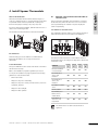
1. Uponor Control System
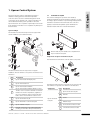
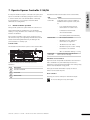
Controller C-55/56
The controller manages the operation of the actuators,
following a demand from the thermostats for heating or cooling,
according to Uponor Interface I-75/76 settings and temperature
information received from the thermostats. The controller is
typically located near the hydraulic system manifolds. The
illustration below shows the controller with actuators.
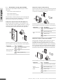
System example
The illustration below shows an Uponor Control System with
several installation options and thermostats.
6
7
24 V
24 V
5
24 V
1
8
Observe that only 24 V actuators are compatible with
Uponor Controller C-55/56.
2
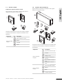
Components of Uponor Controller C-55/56
The illustration below shows the controller and its components.
3
3
4
2
4
5
The table below describes the components of a typical
installation. The item numbers correspond to the numbers in the
illustration.
Item
6
Description
1
Uponor Thermostat with display T-75
2
Uponor Thermostat T-55
3
Uponor Thermostat T-54 Public
Component
4
Uponor Thermostat T-54 Public with floor sensor.
The floor sensor is used for maximum or minimum
limitation of the floor temperature, regardless of
the room temperature. Uponor Thermostat T-54
Public can also be used with an outdoor sensor
5
Uponor Controller C-55/56
6
Uponor Antenna for controller C-55/56
Uponor Controller
C-55/56
7
8
1
The table below describes the components of the controller. The
item numbers correspond to the numbers in the illustration.
Item
Description
1
Uponor Controller C-55/56
2
Antenna
3
Screws
4
Adhesive strips
Uponor Interface I-75/76
5
0.3 m antenna connection cable
External connection box for pumps (third-party
product, just schematic example in illustration)
6
3 m antenna connection cable
U P O N O R C O N T R O L S Y S T E M – I N S TA L L AT I O N A N D O P E R AT I O N M A N U A L
9
1.2
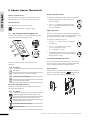
Components of Uponor Thermostat T-55
Thermostats T-75, T-55, and T-54 Public
The thermostat temperature settings are adjusted using the dial,
which is removed to set minimum/maximum temperatures. The
21°C position is marked with a larger line.
UK English
Uponor Control System Radio includes three types of indoor
thermostats:
•
Uponor Thermostat with display T-75
•
Uponor Thermostat T-55
•
Uponor Thermostat T-54 Public
2
The thermostats communicate with the controller through radio
transmission and are used either individually or in combination
with each other. They use the same battery type.
3
1
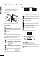
Components of Uponor Thermostat with display T-75
4
The thermostat shows the ambient or set temperature on the
display. Temperature settings are adjusted using the +/- buttons
on the front. The thermostat is affected by the temperature of
surrounding surfaces as well as the ambient air temperature.
1
2
1
Uponor Thermostat
with display T-75
Description
Uponor Thermostat with
display T-75
2
Screws
3
Batteries (AAA 1.5 V)
Item
Description
1
Uponor Thermostat T-55
2
Batteries (AAA 1.5 V)
3
Adhesive strips
4
Screws
Components of Uponor Thermostat T-54 Public
The table below describes the components of the thermostat.
The item numbers correspond to the numbers in the illustration.
Item
Component
Uponor Thermostat
T-55
3
Component
The table below describes the components of the thermostat.
The item numbers correspond to the numbers in the illustration.
The thermostat is designed for public locations. The controls
are hidden by a cover, which must be removed to set the
temperature. An alarm is triggered when the cover is opened.
External sensors for underfloor heating or outdoor temperature
can be connected to Uponor Thermostat T-54 Public, which is
also required when using Uponor Remote access module R-56.
The table below describes the components of the thermostat.
2
3
1
4
The item numbers correspond to the numbers in the illustration.
Component
Uponor
Thermostat T-54
Public
10
Item
Description
1
Uponor Thermostat T-54 Public
2
Batteries (AAA 1.5 V)
3
Adhesive strips
4
Screws
U P O N O R C O N T R O L S Y S T E M – I N S TA L L AT I O N A N D O P E R AT I O N M A N U A L
Interface I-75/76
1.4
Components of Uponor Interface I-75/76
Interface with controller kit
Uponor Interface I-75/76 can be purchased in a kit together
with Uponor Controller C-55/56.
UK English
1.3
Uponor Interface I-75/76 enables centralised and optimised
management of the Uponor Control System.
1
2
1
2
4
3
4
3
5
6
9
The table below describes the components of Uponor Interface
I-75/76. The item numbers correspond to the numbers in the
illustration.
Component
Uponor Interface
I-75/76
Item
8
Description
1
Uponor Interface I-75/76
2
Bracket
3
2 m cable
4
Screws
7
10
The table below describes the components of the interface with
controller kit. The item numbers correspond to the numbers in
the illustration.
Component
Uponor Controller
C-55/56
Item
1
Uponor Controller C-55/56
2
Antenna
3
Adhesive strips
4
Screws for controller and
antenna
0.3 m antenna connection
cable
3 m antenna connection
cable
5
6
Uponor Interface
I-75/76
U P O N O R C O N T R O L S Y S T E M – I N S TA L L AT I O N A N D O P E R AT I O N M A N U A L
Description
7
Uponor Interface I-75/76
8
Bracket
9
Cable
10
Screws for interface
11
1.5
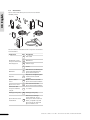
Accessories
UK English
Uponor offers a wide variety of accessories for use with the
standard portfolio.
1
5
3
6
2
4
7
8
9
10
11
The item numbers in the table below correspond to the numbers
in the illustration.
Component
Attachment options
for Uponor Thermostat
with display T-75
1
Table stand
2
Wall bracket
3
Adhesive strips
4
Screws
Wall frame for use with Uponor
Thermostat T-54 Public and
Uponor Thermostat T-55
Repeater to strengthen signal
between thermostat and
controller
Outdoor sensor for use with
Uponor Thermostat T-54 Public
Floor sensor for use with
Uponor Thermostat T-54 Public
Wall frame
5
Repeater
6
Uponor outdoor
sensor
7
Uponor Floor sensor
8
Connection cable
for Uponor Interface
I-75/76
9
15 m cable
Heating/cooling relay
10
Heating/cooling relay
11
Remote access through
mobile telephone, for use
with Uponor Thermostat T-54
Public; compatible only with
Uponor Controller C-56 and
Uponor Interface I-76
Uponor Remote access
module R-56
12
Item Description
U P O N O R C O N T R O L S Y S T E M – I N S TA L L AT I O N A N D O P E R AT I O N M A N U A L
Uponor Control System
Uponor Interface I-75/76
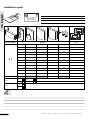
Uponor recommends following the process described below to
guarantee the best possible installation results.
Follow the process described below to install the Uponor
Interface I-75/76.
Stage Description
1
Prepare for installation
Page
Stage
Description
14
1
Attach Interface I-75/76 to bracket
23
2
Wire Interface I-75/76 to Controller
C-55/56
23
Page
2
Install controller antenna
15
3
Attach controller to wall
15
4
Connect components to controller
16
3
Optional: connect multiple controllers
24
5
Optional: connect heating/cooling input
16
4
Use navigation keys
25
6
Optional: connect pump management
17
5
Set language
25
7
Connect controller to AC power
17
6
Set time and date
25
7
Access Installer level
26
8
Optional: set controller IDs
26
9
Optional: set pump management
26
8
Test actuators
18
9
Optional: connect Thermostat T-54 Public to
external sensor
19
10
Register thermostats in controller
21
10
Display actuator status
27
Set exercise schedule
27
11
Install Thermostat with display T-75
21
11
12
Install Thermostat T-54 Public and T-55
22
12
Optional: activate cooling management
27
14
Test communication
22
13
27
15
Complete controller installation
22
Optional: heating/cooling in separate
systems (Controller C-56 only)
14
Complete Interface I-75/76 installation
28
15
Optional: room by-pass
(Interface I-76 only)
28
16
Optional: auto-balance
(Interface I-76 only)
28
17
Room check (Interface I-76 only)
28
18
Supply diagnostics (Interface I-76 only)
29
19
Optional: comfort setting
(Interface I-76 only)
29
U P O N O R C O N T R O L S Y S T E M – I N S TA L L AT I O N A N D O P E R AT I O N M A N U A L
UK English
2. Install Uponor Control System
13
UK English
Example installation
2.1
In the example installation illustrated below, the Uponor
Thermostat with display T-75 01 controls channels 01a, 01b and
02a, 02b. The external sensors attached to Uponor Thermostat
T-54 Public 01 and 10 communicate the floor temperature to
the Uponor Controller C-55/56. The Uponor Thermostat with
display T-75 03 controls channels 03 and 04.
Before installing the Uponor Control System:
Prepare for installation
•
Check the contents of the packages against the packing list
to ensure that all components are present.
•
Check if an external sensor is to be installed with Uponor
Thermostat T-54 Public.
•
Study the wiring diagram in the fold-out or inside the
Uponor Controller C-55/56 cover.
To determine the best positions, following these guidelines:
24 V
24 V
24 V
24 V
24 V
24 V
24 V
24 V
•
Install an Uponor Controller C-55/56 with antenna close to
each manifold.
•
An AC power outlet is required to connect Uponor
Controller C-55/56 to power.
•
Protect installation locations from running and dripping
water.
24 V
: Radio/Program connection
: Cable connection
Note that only 24 V actuators are compatible with
Uponor Controller C-55/56.
14
U P O N O R C O N T R O L S Y S T E M – I N S TA L L AT I O N A N D O P E R AT I O N M A N U A L
Refer to the installation preparation guidelines (see section
2.1 on previous page), and use the following guidelines when
positioning the controller:
•
Position the controller just above the manifold. Check the
position of the 230 V power outlet.
•
Check that the cover of the controller can be removed
easily.
•
Check that connectors and switches are easily accessible.
UK English
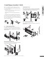
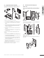
3. Install Uponor Controller C-55/56
Attach antenna to wall
When attaching the antenna to the wall, the 3 m antenna cable
can be used. The illustration below shows the antenna attached
to the wall with screws or double-sided adhesive strips.
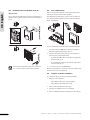
The controller must be attached horizontally on a wall. There is
a risk of overheating if there is a high ambient temperature or if
the controller is attached vertically or on a horizontal surface, as
shown in the illustration below.
9
10
11
9
10
11
12
12
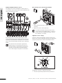
3.2
Attach controller to wall
The illustration below shows how to attach the controller to the
wall with screws.
1
3.1
Install controller antenna
The antenna can be attached to the back of the controller or
to the wall. If the controller is installed inside a metal cabinet,
the entire antenna must be outside the cabinet, as shown in the
illustration below.
2
3
1
2
3
Attach antenna to controller back
The illustration below shows the antenna attached to the back
of the controller using the 0.3 m antenna cable.
9
10
11
12
U P O N O R C O N T R O L S Y S T E M – I N S TA L L AT I O N A N D O P E R AT I O N M A N U A L
15
3.3
Connect components to controller
3.4
UK English
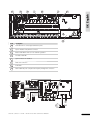
Refer to the wiring diagram in the fold-out of this document.
The illustration below shows the inside of Uponor Controller
C-55/56.
Optional: connect heating/cooling input
If the system is equipped with a cooling unit (requires additional
products), the Uponor Control System can manage the heating/
cooling switch input with the controller.
The heating/cooling input is controlled by a dry contact that
functions as either an auxiliary control system or two-position
relay.
•
When the relay is open, the system is in heating mode.
•
When the relay is closed, the system is in cooling mode.
To avoid damaging the Uponor Control System do not
apply a voltage across the Uponor Controller C-55/56
heating/cooling input.
The list below describes the numbered items in the illustration.
Item
Description
1
Terminal block for connecting antenna and options
2
Uponor Interface I-75/76 RJ-9 connector
3
Registration buttons and LEDs for channels 01 to 12
4
Test button and LED
5
Quick connectors for actuators
6
Socket for connecting data stick
7
Power LED
8
50 Hz 230 V AC power compartment and pump
management connection
The list below describes the numbered items in the illustration.
Item
Connect actuators to controller
Each thermostat can control one or more channels. To
simplify installation and maintenance, Uponor recommends
that actuators controlled by the same thermostat be wired in
sequence to the channels.
STOP
16
The illustration below shows components of the heating/
cooling system.
Description
1
Heating/cooling relay
2
Heating/cooling contact
3
Controller heating/cooling input (potential-free dry
contact)
4
Example of different type of heating/cooling relay
input
For further information, see the heating/cooling relay
documentation.
Identify the room supplied by each loop on the manifold
and determine which channel it must be connected to.
U P O N O R C O N T R O L S Y S T E M – I N S TA L L AT I O N A N D O P E R AT I O N M A N U A L
Optional: connect pump management
The Uponor Control System can operate a circulation pump,
which stops when there is no demand for heating or cooling.
See the circulation pump supplier documentation and
the relevant Uponor wiring diagram before performing
the connection.
A pump for all manifolds and controllers can be connected to
the closest controller.
UK English
3.5
If separate pumps are used for each manifold, each pump can
be connected to be run by its own controller, as shown in the
illustration below.
Shared pump
Individual pump
Uponor Controller C-55/56 cannot supply power source
for the pump.
Uponor Controller C-55/56 uses a dry contact connection on
the terminal block to control the circulation pump.
The electrical circuits of the pump must be protected by a
circuit breaker with a maximum rating of 6 A.
The illustration below shows how to connect circulation pump
management to the controller:
C-55/56
To connect circulation pump management:
1
Ensure the power is disconnected.
2
Open the 230 V compartment and attach the cover to the
hanger.
3
Connect the L wire from/to the pump via the relay.
4
Close the 230 V compartment.
3.6
Connect controller to AC power
To connect one Uponor Controller C-55/56 to AC power:
1
Check that the wiring is complete for the actuators and
antenna.
2
Check that the 230 V compartment is closed.
3
Connect the controller plug to the AC power.
U P O N O R C O N T R O L S Y S T E M – I N S TA L L AT I O N A N D O P E R AT I O N M A N U A L
17
3.7
Test actuators
UK English
Uponor Controller C-55/56 manages the temperature set point.
When a temperature change occurs, the actuator opens or
closes the valve to adjust the heat supply.
To test the actuators:
1
2
18
Press the button of the selected channel.
•
The LED comes on, which means that the controller
receives a signal and powers the actuator on the
selected channel. The time for actuator opening is about
5 minutes.
•
If the LED does not come on, then refer to the
troubleshooting section.
Press the test button twice to end the actuator test or wait
for 10 minutes for the system to end the test.
U P O N O R C O N T R O L S Y S T E M – I N S TA L L AT I O N A N D O P E R AT I O N M A N U A L
Label room thermostats
Label the thermostats with the channel numbers they are to
control, for example, 02, 03. For a system with Uponor Interface
I-75/76 and several controllers, add the ID of each Uponor
Controller C-55/56, for example, 1.02, 1.03, 2.02, 2.03.
For Uponor Thermostat T-54 Public, add information for floor or
outdoor sensors when applicable.
The illustration below shows where to label the thermostats.
4.1
UK English
4. Install Uponor Thermostats
Optional: connect Thermostat T-54 Public to
external sensor
Uponor Thermostat T-54 Public has a terminal for connecting
an external sensor, which can be a floor sensor or an outdoor
sensor (used with Uponor Interface I-75/76 to display the
outdoor temperature).
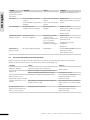
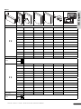
Set switches for external sensors
The configuration switches must be set according to the way in
which the thermostat is used, as shown in the illustration.
Insert batteries
All thermostat types use two alkaline 1.5 V AAA batteries.
Ensure that the batteries are correctly inserted in the
thermostats.
The table below describes how to set the switches shown in
the illustration above, according to the way Uponor Thermostat
T-54 Public is used.
Locate thermostats
The Uponor Wall frame can be used to hide marks on the wall or
the wall box if necessary.
Refer to the installation preparation guidelines (see section
2.1 Prepare for installation on page 14) and use the following
guidelines to locate all thermostats:
•
On an interior wall.
•
Away from any source of humidity.
•
Away from any source of heat, such as television, electronic
equipment, fireplace.
•
Away from direct sunlight.
•
Away from water splashes.
Switch
1
Switch
2
Switch
3
Switch
4
Used as a standard
room thermostat
Off
Off
Off
Off
Used with a floor
sensor, max.
limitation
On
Off
Off
Off
Used with a floor
sensor, min.
limitation
On
Off
Off
On
Used with an outdoor
sensor
Off
On
Off
Off
Technical alarm
Off
Off
On
Off
Used with Uponor
Remote access
module R-56
Off
Off
Off
On
External (floor)
sensor for room
temperature
Off
On
Off
On
Function
The switch must be set before the thermostat is
registered.
U P O N O R C O N T R O L S Y S T E M – I N S TA L L AT I O N A N D O P E R AT I O N M A N U A L
19
Wire external sensor to Thermostat T-54 Public
Example installation with floor sensors
UK English
The example below shows an installation of thermostats in a
room with floor sensors. Uponor Thermostat T-54 Public 01 and
10 are connected to floor sensors.
1
2
24 V
24 V
24 V
24 V
24 V
24 V
24 V
24 V
1
Connect cable from the floor or outdoor sensor (nonpolarized).
2
Tighten the screws to fix the cable wires
For accurate temperature: attach the outdoor sensor
on the north side of the building where it is unlikely to
be exposed to direct sunlight. Do not place it close to
doors, windows, or air outlets.
24 V
Adjust floor sensor settings
In the example, Uponor Thermostat with display T-75 #01
controls channels 01a, 01b, 02a, and 02b. Uponor Thermostat
T-54 Public communicates floor temperature to the controller.
Uponor Thermostat with display T-75 #03 controls channels 03
and 04.
The Uponor Thermostat T-54 Public sends the external sensor
values to the controller. Temperature settings can be adjusted by
using the potentiometer, as shown in the illustration below.
If the external sensor thermostat is registered to a
channel used by a room thermostat, then the room
thermostat must be registered before registering the
external sensor thermostat. Thermostats with floor
sensors have a higher priority than room thermostat.
30
25
35
40
20
45
To adjust floor minimum or maximum temperature:
1
20
Select the required temperature with the potentiometer.
U P O N O R C O N T R O L S Y S T E M – I N S TA L L AT I O N A N D O P E R AT I O N M A N U A L
Register thermostats in controller
The illustration below shows how to register the various room
thermostats associated with Uponor Controller C-55/56.
4.3
Install Thermostat with display T-75
Attach to wall
UK English
4.2
The Uponor Thermostat with display T-75 can be attached to a
wall with screws or adhesive strips, as shown in the illustration
below.
To register room thermostats in the controller:
1
Press and release the Test button. The test LED comes on.
2
Press the button of preferred channel. The channel LED
flashes.
3
Using a pointed instrument, gently press on the registration
button of the thermostat until the channel LED in the
controller is constantly on.
4
Repeat steps 2 and 3 until all used room thermostats are
registered.
5
Press and release the Test button to end registration. The
test LED goes off.
Wall bracket
The thermostat can be attached to a wall with a wall bracket, as
shown in the illustration below.
1
2
To register a room thermostat for multiple channels in the
controller:
1
Press and release the Test button. The test LED comes on.
2
Press and release the button of the chosen channels in the
controller. The channel LEDs flash.
3
Using a pointed instrument, gently press the registration
button of each thermostat until the channel LEDs in the
controller are constantly on.
4
When all thermostats are registered, press and release the
Test button. The test LED goes off.
Attach to table stand
The illustration below shows how to attach the thermostat to a
table stand.
To deregister already registered thermostats see section 6.2
Deregister channels in controller on page 30.
U P O N O R C O N T R O L S Y S T E M – I N S TA L L AT I O N A N D O P E R AT I O N M A N U A L
21
4.4
Install Thermostat T-54 Public and T-55
4.5
Uponor recommends testing the communication between the
thermostats and the controller after installation.
Attach to wall
UK English
Test communication
Uponor Thermostat T-54 Public and T-55 can be attached to a
wall with screws or adhesive strips, as shown in the illustration
below.
The illustration below shows the location of the test button of
the controller and the registration buttons of Thermostat T-54
Public, T-55 and T-75.
To test communication between controller and all thermostats:
To avoid unnecessary alarms, make sure to fasten the
cover correctly on Uponor Thermostat T-54 Public.
1
Press and release the Test button. The test and channel
LEDs with registered thermostats comes on.
2
Using a pointed instrument, gently press the registration
button of each registered thermostat.
3
•
Communication OK: LEDs for the channels registered to
the thermostat go off.
•
No communication: LEDs for the channels registered to
the thermostat stay on.
To exit test mode, press the Test button.
When two thermostats are connected to the same channel, each
thermostat must be tested separately.
4.6
Complete controller installation
To complete the Uponor Controller C-55/56 installation:
1
22
Check the entire installation:
•
Check that the antenna is correctly installed
•
Check that the thermostats have power
2
Close all controller and thermostat covers.
3
Complete the installation report in this manual.
4
Give the manual and all system information to the end user.
U P O N O R C O N T R O L S Y S T E M – I N S TA L L AT I O N A N D O P E R AT I O N M A N U A L
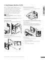
Refer to the installation preparation guidelines (section 2.1
Prepare for installation on page 14). Uponor Interface I-75/76
can be attached to a wall or to the cover of the controller.
UK English
5. Install Uponor Interface I-75/76
Attach Interface I-75/76 to bracket
The illustration below shows how to attach Uponor Interface
I-75/76 to the bracket.
Additional controllers must be installed for installations with
more than one manifold or more than 12 channels. One Uponor
Interface I-75/76 supports a maximum of three controllers,
where each controller must be equipped with an antenna.
WARNING
50 Hz 230 V AC power.
Disconnect all power before installing or changing the
device wiring.
Uponor Interface I-75/76 is attached to a bracket that in turn is
attached to either a wall or the controller cover.
5.1
Attach bracket to wall
The illustration below shows how to attach a bracket to a wall.
1
3
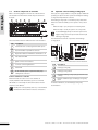
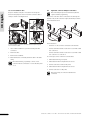
Wire Interface I-75/76 to Controller C-55/56
Use RJ-9 connectors
If Uponor Interface I-75/76 is less than 2 m from Uponor
Controller C-55/56, then use the 2 m cable equipped with RJ-9
connectors at each end, as shown in the illustration below.
2
3
4
4
3
2
1
4
Attach bracket to controller cover
The illustration below shows how to attach the bracket to the
cover of the controller.
2
To wire Uponor Interface I-75/76 to Uponor Controller C-55/56
with the RJ-9 cable:
1
Connect the RJ-9 cable to the controller.
2
Secure the cable in the clamp.
3
Connect the RJ-9 cable to the back of Uponor Interface
I-75/76.
4
Secure the cable in the cable guide.
1
U P O N O R C O N T R O L S Y S T E M – I N S TA L L AT I O N A N D O P E R AT I O N M A N U A L
23
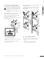
Use 15 m installation cable
5.2
UK English
If Uponor Interface I-75/76 is more than 2 m from Uponor
Controller C-55/56, use the 15 m four-wire connector cable or
similar, as shown in the figure below.
Optional: connect multiple controllers
STOP
Note that multiple Uponor Controller C-55/56 units
require software programming.
Up to three controllers can be connected to the same Uponor
Interface I-75/76. All controllers require an antenna, as shown
in the illustration below.
5
6
7
4
2
3
8
1
To wire Interface I-75/76 to the Controller C-55/56 using the
15 m connector cable:
In the illustration:
•
Controller 1 is the controller connected to the interface
1
Insert a thin screwdriver to open the relevant push-wire
connection.
•
Connect terminals 5 and 6 of controller 2 to terminals 5 and
6 of controller 1.
2
Push in the wire.
•
3
Remove the screwdriver.
Connect terminals 7 and 8 of controller 3 to terminals 7 and
8 of controller 1 or controller 2.
4
When all wires are connected, fasten the cable in the cable
clamp.
STOP
Note that the wiring is polarized, so wire 1 on the
controller must be connected to 1 on the interface, and
so on.
To connect up to three controllers to the interface:
1
Check that the wiring is complete.
2
Check that the 230 V compartments are closed.
3
Connect controllers 2 and 3 to AC power.
4
Check that the 230 V compartments are closed.
5
Connect controller 1 to AC power.
STOP
24
Note the polarity of connections between the
controllers.
U P O N O R C O N T R O L S Y S T E M – I N S TA L L AT I O N A N D O P E R AT I O N M A N U A L
Use navigation keys
5.5
Each of the five navigation keys on Uponor Interface I-75/76
has dual functions, as described in the table below.
Key
Functions
Displays next menu
The Set Date/Time screen opens automatically when the
language is set.
or Moves to next field
or Moves to previous
Displays previous
field
menu; pressing and
holding on the menu
screen displays the
main Uponor screen
Moves to line above or Increases the value
Moves to line below
or Decreases the value
Displays next screen
or Confirms selections;
displays the screen
of the current menu
•
Press any navigation key to activate backlighting.
•
Press OK to go to the main menu.
5.4
Set time and date
UK English
5.3
Select time and date with keys, as shown in the illustration
below.
Set language
When starting up Uponor Interface I-75/76 for the first time,
the language menu appears.
To set the time and date on Uponor Interface I-75/76:
To access the language menu when Interface I-75/76 is
installed:
1
On the Uponor screen, press the OK button to access the
Main Menu.
2
Select Settings and press OK.
3
Select System Parameters and press OK.
4
Select Language and press OK.
5
Now select the preferred language from the list and press
OK to confirm.
1
Select Hours.
2
Set the hour.
3
Select Minutes.
4
Set the minutes and continue to set the date.
5
Press OK to confirm the settings.
U P O N O R C O N T R O L S Y S T E M – I N S TA L L AT I O N A N D O P E R AT I O N M A N U A L
25
5.6
Access Installer level
5.7
UK English
Uponor Interface I-75/76 has three access levels (Interface I-76
displays these icons only):
Basic
Optional: set controller IDs
Controller IDs are required only when two or three controllers
are used. The IDs can be set only when Uponor Interface
I-75/76 is set to Installer level access.
To set controller IDs for Interface I-75/76:
Advanced
1
On the Uponor screen, select Main Menu > Settings >
System Parameters > Controller ID.
Installer
2
Select Reset Controller ID and
press OK.
3
Select Yes and press OK.
4
Press the down arrow key to move
the cursor to Set Controller ID and
press OK.
5
The message >1. Controller< flashes.
Press the Test button on controller
1, which is connected to Interface
I-75/76.
6
Select >2. Controller<. Press the Test button on controller
2, which is connected to terminals 5 and 6 of controller 1.
The Installer level gives access to:
•
Information menu
•
All parameter settings for the advanced level
•
Auto-balance (Interface I-76 only)
•
Room check (Interface I-76 only)
•
Heating/cooling
•
Pump management
•
Controller ID
•
By-pass (Interface I-76 only)
To access Installer level:
1
On the Uponor screen, simultaneously press
the Advanced screen appears (10 seconds).
2
Press OK to confirm the Advanced
access level. The Uponor screen
appears again.
3
On the Uponor screen, select Main Menu > Settings >
System Parameters > Access level.
4
On the Access level screen,
simultaneously press and until the
Installer screen appears (10 seconds).
and
until
(7) Select the >3. Controller<. Press the Test button on
controller 3, the controller connected to terminals 7 and 8
of controller 1 or controller 2.
8
When all controllers have IDs, press OK to confirm. The
Uponor screen appears.
5.8
5
Set pump management if more than one controller is connected
and the pump relay is used.
Press OK to confirm the Installer level.
The Uponor screen appears again and
Installer level access is granted.
The system automatically returns to Advanced level after
10 minutes of inactivity.
26
Optional: set pump management
STOP
Shared pumps must not be connected to more than one
Uponor Controller C-55/56.
To set pump management through Uponor Interface I-75/76:
1
On the Uponor screen, select Main Menu > Settings >
System Parameters > Pump Management.
2
Choose Common or Individual and
press OK.
U P O N O R C O N T R O L S Y S T E M – I N S TA L L AT I O N A N D O P E R AT I O N M A N U A L
Display actuator status
To display actuator status:
1
Set Interface I-75/76 access to Installer level.
2
On the Uponor screen, select Main Menu > Information >
Rooms.
3
Select the desired room and press OK.
The screen displays the Actuator
status:
•
OK – Normal operation.
•
Alarm – A short circuit or similar problem is reported.
5.11 Optional: activate cooling management
Cooling mode must be activated in Uponor Interface I-75/76 if
cooling is installed (requires additional product).
To activate cooling management Uponor Interface I-75/76 must
have Installer level access, then follow procedure below:
1
On the Uponor screen, select Main Menu > Settings >
System Parameters > Cooling Available.
2
Select Yes and press OK.
3
Select:
5.10 Set exercise schedule
•
Auto heating/cooling – manages
the switchover automatically by
an Uponor heating/cooling relay
connected to a controller.
•
Forced heating – manually
switches to Heating mode;
information from a heating/cooling
relay is ignored.
•
Forced cooling – manually
switches to Cooling mode;
information from a heating/cooling
relay is ignored.
The exercise schedule maintains the functionality of the valves
and pumps. A 5-minute activation is initially scheduled for every
week. Change this setting if needed.
To set the exercise schedule:
1
From the Uponor screen, select Main Menu > Settings >
System Parameters > Valve/Pump Exercise.
2
Select the desired parameter and
press OK.
3
Set the time and date for the exercise
and press OK.
UK English
5.9
Press OK. The system automatically
returns to Advanced level after 10
minutes.
5.12 Optional: heating/cooling in separate
systems (Controller C-56 only)
It is possible to apply the Uponor Control System for heating
and cooling simultaneously with one thermostat. This control
setup is typically used when combining underfloor heating with
ceiling cooling panels.
This requires two controllers: one set in heating mode and one
set in cooling mode. Since they are in different modes, the
controllers must not be interconnected.
Note that the set point of the thermostat is defined as the
heating set point. The cooling set point is defined as the
heating set point +1.5 degrees. This creates a dead zone
between heating and cooling to increase system performance
and stability.
U P O N O R C O N T R O L S Y S T E M – I N S TA L L AT I O N A N D O P E R AT I O N M A N U A L
27
UK English
5.13 Complete Interface I-75/76 installation
5.15 Optional: auto-balance (Interface I-76 only)
The illustration below shows how to complete the Uponor
Interface I-75/76 installation.
The auto-balance function removes the need for manual
balancing of the manifold at installation. The principle for
automatic balancing is that the energy required by each loop
is distributed in pulses. The length of the pulses in each loop is
calculated from the actual heat demand of the room. The autobalance function requires an Interface I-76 set to Installer level
access. To activate the auto-balance function of Interface I-76:
1
On the Uponor screen, select Main Menu > Settings >
System Parameters > Auto Balance.
2
In the Auto Balance screen, select
Active and press OK. The auto-balance
function is now activated.
When Auto-balancing is used all balancing valves on the
manifold must be fully open.
To complete the Interface I-75/76 installation:
1
5.16 Room check (Interface I-76 only)
Check the entire installation.
•
Check that Interface I-75/76 and thermostats have
power.
•
Check Interface I-75/76 for alarms.
The room check function checks that the loops and thermostats
are correctly mapped. It works best at night to minimize
interference from sunlight, kitchen appliances, and so on. It
works only if there is a heat demand and the heating is running.
You can choose which rooms to include in the test. To start the
room check Interface I-76 must be set to Installer level access:
2
Close the controller cover.
3
Fill in the installation report included in this manual and
give all information about the system to the end user.
1
On the Uponor screen, select Main Menu > Settings >
System Parameters > Room Check.
5.14 Optional: room by-pass (Interface I-76 only)
2
On the Room Check screen, select
Room Check Start/Stop and press
OK.
3
On the new Room Check screen the Room check function
can be either started or stopped. Confirm selection by
pressing OK.
It is possible to use one room per controller as a by-pass. This
means that the loops are opened for this room when all other
loops on the controller are closed. This is needed by some heat
pumps that need a minimum flow and load to operate correctly.
If more than one controller is used it is possible to choose one
for each controller. To reach the by-pass settings Interface I-76
must be set to Installer level access.
28
1
On the Uponor screen, select Main Menu > Settings >
Rooms > By Pass.
2
Select Controller from the list and
confirm by pressing OK.
3
Choose the relevant room for the
by-pass function.
U P O N O R C O N T R O L S Y S T E M – I N S TA L L AT I O N A N D O P E R AT I O N M A N U A L
5.17 Supply diagnostics (Interface I-76 only)
1
On the Uponor screen, select: Main Menu > Settings >
System Parameters > Supply Diagnostic.
2
On the Supply Diagnostic screen,
select Activate and press OK.
UK English
Supply diagnostics is a help function that can be activated in
Uponor Interface I-76. It monitors the behaviour of the system
and issues a warning if the system is under- or overpowered.
Underpowered means that the system cannot reach its set
point in one or more zones. This can be caused by a supply
temperature or pump speed that is too low. The opposite case,
overpowered, is caused by a supply temperature that is too
high. To activate the supply diagnostic screen:
5.18 Optional: comfort setting (Interface I-76 only)
The comfort setting function adds background heating for
increased comfort in selected rooms. This means that the room
is heated even if the room temperature is above the set point.
This prevents the floor from cooling when using a fireplace.
Note that this feature must be used selectively to prevent
unnecessary energy consumption. To activate the comfort
setting function:
1
On the Uponor screen, select: Main Menu > Settings >
Rooms > Comfort Setting.
2
Select Controller in the Controller
List screen and press OK.
3
Select the room you want to apply the
comfort setting for and press OK.
4
Select the percentage for the comfort
setting with the
and
buttons.
5
Confirm by pressing OK.
U P O N O R C O N T R O L S Y S T E M – I N S TA L L AT I O N A N D O P E R AT I O N M A N U A L
29
UK English
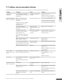
6. Troubleshoot installation
The table below describes troubleshooting after installation.
Failure
Indication
Causes
Solution
System does not start
Power LED off in Uponor
Controller C-55/56
No voltage
Check that the controller is
connected to the AC power
and that the wiring in the 230
V compartment is correct
Poor radio reception
Repeated radio alarms
Antenna installed inside a metal
cabinet or too close to other
shielding objects
Change the antenna location.
If the problem persists,
contact the installer for help
checking radio transmission
and test with a radio repeater
Building structure unfavourable
for radio transmission
Thermostats is not
registrating
6.1
Channel LEDs in Uponor
Controller C-55/56 continue
flashing
Reset controller
Antenna is not installed
correctly
Check wiring and antenna
connection
To cancel a channel registration:
If problems, such as inaccurate channel registration exist, reset
the controller. The illustration below shows the location of the
reset button in Uponor Controller C-55/56.
1
Press the Test button. The test and channel LEDs with
registered thermostats come on.
2
Select the channel to cancel and press the button until the
LED flashes and then goes off.
3
Press the Test button to end registration. The test LED goes
off.
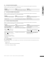
6.3
Reset Interface I-75/76
If Uponor Interface I-75/76 is not functioning as expected,
then reset the device, using the button shown in the illustration
below.
To reset Uponor Controller C-55/56:
1
Press the Test button until the test LED flashes and all
LEDs except the power LED go off. All parameters are
erased.
2
Installation and registration are required after resetting the
controller.
6.2
Deregister channels in controller
To reset Uponor Interface I-75/76:
When a channel is inaccurately registered, it is possible to cancel
the registration, as shown in the illustration below.
1
Gently press the Reset button.
2
This resets time and date. There is no need to register the
thermostats again.
2
1
30
3
U P O N O R C O N T R O L S Y S T E M – I N S TA L L AT I O N A N D O P E R AT I O N M A N U A L
If no Uponor Interface I-75/76 is connected to the system, then
Uponor recommends occasionally opening the controller cover
to check for alarms. The controller LED flashes continuously
for general alarms, so it is necessary to determine which
thermostats are issuing alarms.
7.1
The table below describes the status of the controller LEDs.
LED
Status
Power LED
Power LED of the controller is always on
and flashes when a problem occurs, such
as:
Normal controller operation
•
Loss of radio transmission from a
thermostat for more than 3 hours
•
Low batteries in a thermostat
•
Short-circuited actuator
•
Cover alarm (Thermostat T-54 Public)
•
On – actuators activated
•
One flash a second – waiting for
thermostat to be registered
•
Two flashes a second – Alarm
•
One flash every two seconds – waiting
for actuators to be activated
•
Off – no demand for heating or cooling
During normal operation the power LED of the controller is on.
All the channel LEDs are off when there is no demand for
heating or cooling. The LEDs come on when the corresponding
actuators are activated.
No more than six actuators can be in the opening process at
the same time. They open sequentially. The LED of the seventh
actuator and followings flash while they are waiting for the
previous actuators to be fully open.
Channel LEDs
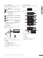
Controller LEDs
The illustration below shows the position of the controller LEDs.
2
1
Flashing AC
power LED
3
UK English
7. Operate Uponor Controller C-55/56
A flashing AC power LED indicates an
alarm or an error message.
Automatic exercise function
The table below describes the numbered items in the
illustration.
Item
Uponor Controller C-55/56 has an automatic exercise function
that is scheduled to be performed weekly. The exercise is
designed to prevent the pump and actuators from seizing if they
have not been activated for a long period.
Description
1
Test button and LED
2
Power LED
3
Channel LEDs
If the system includes an Interface I-75/76, the exercise
function can be used at any time.
Clean controller
Use a dry, soft cloth to clean Uponor Controller C-55/56.
STOP
U P O N O R C O N T R O L S Y S T E M – I N S TA L L AT I O N A N D O P E R AT I O N M A N U A L
Do not use detergent or any other liquids.
31
UK English
8. Operate Uponor Thermostats
Batteries for thermostats
Change temperature format
All thermostats use two alkaline 1.5 V AAA batteries. Ensure
that the batteries are correctly inserted in the thermostats.
To change the temperature format to Celsius or Fahrenheit:
1
Simultaneously press the + and - keys until the
SEL menu appears.
2
Press + or - to change the temperature format
(°C or °F) and wait until the thermostat returns
to the initial display.
Clean thermostats
Use a dry soft cloth to clean the thermostats.
STOP
Do not use detergent or any other liquids.
Adjust temperature
8.1
Operate Thermostat with display T-75
Use the + or - key of the thermostat to adjust the temperature.
To reset the temperature set point to the startup value of 22.0°C
(72.0 °F), gently press the + and - keys simultaneously.
The thermostat displays the room temperature during normal
operation, as shown in the illustration below.
To change the temperature set point:
LCD display
Initial display shows
room temperature
2
Temperature sensor for ambient temperature
3
+ and - keys to set temperatures
4
Thermostat registration button
2
Press + or - to change the set point value:
For °C, setting by 0.5 °C steps.
For °F, setting by 1 °F steps.
3
Wait until the radio transmission icon is displayed,
confirming that the set point is changed, and the
display returns to normal.
The minimum and maximum temperatures (5 °C and 35 °C)
of the thermostat are set and cannot be changed unless the
system is equipped with Uponor Interface I-75/76.
Item Description
LCD display
Press the + or - key. The set point icon and value
are displayed.
Set minimum/maximum temperatures
The table below describes the numbered items in the
illustration.
1
1
Replace batteries
The thermostat is powered by batteries. Replace the batteries
of the thermostat when the symbol
is displayed. The
illustration below shows how to open the thermostat.
Thermostat with display T-75 icons
The table below describes the icons displayed on the Uponor
Thermostat with display T-75.
Icon
Description
Temperature display with menus and a precision of 0.1°
Displayed when setting the temperature set point
Displayed during radio transmission
Temperature format for the display
Low battery indicator
32
U P O N O R C O N T R O L S Y S T E M – I N S TA L L AT I O N A N D O P E R AT I O N M A N U A L
Operate Thermostat T-55
During normal operation the thermostat LED flashes once only
with each radio transmission. The illustration below shows the
parts of the thermostat.
Set minimum/maximum temperatures
The illustration below shows how to set minimum and maximum
temperatures in the thermostat. If the system is equipped with
Uponor Interface I-75/76, all minimum/maximum settings
can be handled from there, and the procedures below are not
necessary.
UK English
8.2
1
1
2
3
The table below describes the numbered items in the
illustration.
To set minimum and maximum temperatures:
Item
Description
1
Room temperature set point dial control
2
Registration button
3
Batteries
4
Radio transmission LED
5
Blue cam to set minimum temperature
6
Red cam to set maximum temperature
1
Remove the dial with a screwdriver.
2
Set the desired minimum temperature of the room with the
blue cam.
3
Set the maximum temperature with the red cam.
Replace batteries
The thermostats are powered by batteries. Replace the batteries
of the thermostat when the red LED inside the thermostat
flashes twice during a heating or cooling demand. The
illustration below shows how to open the thermostat.
Adjust temperature
Use the control dial of the thermostat to adjust the
temperature. The illustration below shows how to adjust the
thermostat temperature set point.
To adjust the thermostat temperature:
•
Rotate the dial clockwise for a higher temperature
•
Rotate the dial anti-clockwise for a lower temperature
U P O N O R C O N T R O L S Y S T E M – I N S TA L L AT I O N A N D O P E R AT I O N M A N U A L
33
8.3
Change temperature set point
Operate Thermostat T-54 Public
UK English
Uponor Thermostat T-54 Public contains a switch that sends
an alarm when the thermostat cover is opened. The alarm is
transmitted by radio, causing both the power LED and related
channel LED to flash.
During normal operation the thermostat LED flashes once only
with each radio transmission.
It is not possible to set minimum and maximum temperatures
using Uponor Thermostat T-54 Public unless Uponor Interface
I-75/76 is installed.
The illustration below shows how to change the temperature set
point in Uponor Thermostat T-54 Public.
The illustration below shows Uponor Thermostat T-54 Public.
1
2
2
To change the Uponor Thermostat T-54 Public temperature
setpoint:
The table below describes the numbered items in the
illustration.
Item
1
Screw for opening the thermostat
2
Terminal for external sensor (non-polarized)
3
Batteries
4
Setpoint temperature potentiometer
5
Configuration switches
6
Floor sensor potentiometer
7
Registration button
8
Radio transmission LED
STOP
34
Description
1
Remove the cover.
2
Select the desired temperature using the potentiometer.
3
Put back the cover and tighten it in place.
Replace batteries
Replace the batteries of the thermostat when the red LED
inside the thermostat flashes twice during a heating or cooling
demand. The illustration below shows how to open the
thermostat.
CAUTION
Thermostats are located in specific areas for optimum
performance. Changing the location of thermostats can
cause abnormal temperature control.
U P O N O R C O N T R O L S Y S T E M – I N S TA L L AT I O N A N D O P E R AT I O N M A N U A L
Adjust floor sensor
UK English
If the system includes a floor sensor, the potentiometer behind
the cover of Uponor Thermostat T-54 Public allows minimum or
maximum temperature settings of the floor sensor.
30
Embedded in concrete or slab
25
35
40
20
45
Embedded in wooden suspended floor
The floor sensor limits the maximum or minimum floor
temperature, regardless of the room temperature. The maximum
limitation can be used to prevent a sensitive floor covering from
exposure to excessive high temperature when there is a high
heat demand.
To change Uponor Thermostat T-54 Public floor sensor settings.
1
Select the desired temperature using the potentiometer.
For information how to set the switches, see section 4.1
Optional: connect Thermostat T-54 Public to external sensor on
page 19.
Sensors, outdoor and external
U P O N O R C O N T R O L S Y S T E M – I N S TA L L AT I O N A N D O P E R AT I O N M A N U A L
35
UK English
9. Operate Uponor Interface I-75/76
Adding Uponor Interface I-75/76 to the Uponor Control System
provides:
•
Centralized management of the underfloor system
•
Rapid display and update of system settings
The illustration below shows the exterior and interior of Uponor
Interface I-75/76.
9.2
Interface I-75/76 main screen
The table below describes icons displayed on the Uponor main
screen:
Icon
Description
Holiday Mode
Alarm/error message
Temperature set point
Temperature measured
Floor temperature (when floor sensor is installed)
The table below describes the numbered items in the
illustration.
Item
Description
1
Screen
2
Navigation keys
3
Fault indicator
4
Reset button
5
Data stick connection
9.1
Batteries sufficiently charged
Batteries discharged, replace batteries
Basic access level (Interface I-76 only)
Advanced access level (Interface I-76 only)
The outdoor temperature is displayed if the system has
Thermostat T-54 Public with an outdoor sensor installed.
Use navigation keys
Each of the five navigation keys on Uponor Interface I-75/76
has dual functions, as described in the table below.
Key
36
9.3
Interface I-75/76 main menu
1
Functions
2
Displays next menu
or
Moves to next field
Displays previous
menu. Pressing and
holding in a menu
screen displays main
Uponor screen
or
Moves to previous
field
Moves to line above
or
Increases value
Moves to line below
or
Decreases value
Displays next screen
or
Confirms selections;
displays screen of
current menu
•
Press any navigation key to activate backlighting.
•
Press OK to go to the main menu.
3
The table below describes the numbered items in the example.
Item Description
1
Upper banner displays menu heading
2
Information zone: the selected line is highlighted
3
Scroll bar
U P O N O R C O N T R O L S Y S T E M – I N S TA L L AT I O N A N D O P E R AT I O N M A N U A L
Access and navigate menu
To access room information from the menu:
1
Press the OK navigation key to display the Main Menu.
2
Select Information and press OK.
The information menu is displayed.
3
4
5
Select Rooms and press OK. The list
of rooms is displayed.
Select the desired room and press
OK. Information for the selected
room is displayed.
Display the desired information
using the navigation keys.
Use and to display the
previous/next screen.
Use
and
to display the
previous/next thermostat.
9.6
Display room information
The digits at the beginning of the room name on the display
mean:
•
1st digit – controller number (1, 2, 3).
•
2nd and 3rd digits – number of the first channel controlled by
this thermostat (01, 02, 03, and so on). If several channels
are controlled by the thermostat, only the lowest channel
number is displayed.
To display room information:
1
On the Uponor screen, select Main Menu > Information >
Rooms.
2
Select the desired room and press OK.
Meanings of the temperature icons as shown in the example
screens below.
Icon Description of use
Select access level
Two access levels are available for operation:
•
Basic allows the users to view basic information but not to
modify settings. Basic mode can be used in a public location
or rented accommodation, for example.
•
Advanced allows users both to view and modify settings.
Measured temperature is 21.2 °C.
Temperature setting for room
when in ECO mode. (Current
setting 19 °C).
Options for current status:
COMF: Comfort mode.
ECO: Economy mode.
To select the access level:
1
On the Uponor screen, select Main Menu > Settings >
System Parameters > Access Level.
2
Select Basic or Advanced and
press OK.
To switch from Basic to Advanced level, on the Uponor screen,
simultaneously press and until the Advanced screen
appears.
Select Advanced and press OK to put the system in advanced
level.
Screen example
If temperature set on thermostat
is outside allowed temperature
range for room, limitation
temperature is displayed as set
point.
Press OK to return to the room list.
9.5
UK English
9.4
This screen is displayed if there is
a floor sensor in the room. Floor
temperature is 23 °C.
Max and Min - Minimum and
maximum floor temperature set
point is displayed.
9.7
Display battery and communication status
To display battery and communication status:
Icon
Description
Screen example
Battery: batteries are sufficiently
charged.
Signal: radio signal from the
thermostat and antenna is good.
Battery: batteries are
discharged.
Signal: radio signal from antenna
or thermostat is poor or faulty.
U P O N O R C O N T R O L S Y S T E M – I N S TA L L AT I O N A N D O P E R AT I O N M A N U A L
37
9.8
Display room thermostat status
To apply holiday mode:
UK English
To display thermostat and actuator status of a room:
Icon
Stat call
Act.
9.9
Description of use
Screen example
Yes: thermostat is calling for
heating (or cooling).
No: thermostat is reporting
that room temperature is OK.
Open: actuators are
powered and open or on
delay and will open soon.
Closed: no power to the
actuators, which are closed
(or closing).
Min.
Minimum set point of room
is set at 20 °C.
Max.
Maximum temperature set
point of room is set at 26 °C.
1
On the Uponor screen, select Main Menu > Holiday
Mode > Apply Holiday Mode.
2
Enter the time and date for the start
of the holiday period and press OK.
3
Enter the time and date for the end
of the holiday period and press OK.
4
Enter the holiday temperature set
point and press OK.
The icon
on the main screen
indicates that the system is in holiday
mode.
To cancel holiday mode:
Select heating or cooling mode
1
On the Uponor screen, select Main Menu > Holiday
Mode > Cancel Holiday Mode.
2
Select Yes and press OK.
To select heating or cooling mode:
System Status
Room Cooling
Heating or cooling
mode is activated for
the whole system.
9.11 Assign room name
The digits at the beginning of the room name on the display
mean:
Enable: Cooling the
room is allowed.
Disable: Cooling the
room is not allowed.
•
1st digit – controller number (1, 2, 3).
•
2nd and 3rd digits – number of the first channel controlled by
the thermostat (01, 02, 03, and so on). If several channels
are controlled by the thermostat, only the lowest channel
number is displayed.
9.10 Use holiday mode
Use holiday mode to set a common temperature reduction for all
rooms for a specified time. The thermostat settings are ignored
during this period.
The reduced holiday set point applies to all installed room
thermostats. The setting range is 5 to 35 °C.
The minimum and maximum thermostat limitations have priority
over the holiday mode. For example, if the maximum/minimum
temperature range of a room thermostat is set to 20 °C to 25 °C,
and holiday mode temperature is set to 15 °C for all rooms, the
temperature for this room will not go below 20 °C.
Floor sensor thermostat settings have priority over holiday
mode maximum and minimum limitations.
38
To assign a room name:
1
On the Uponor screen, select Main Menu > Settings >
Rooms > Room names.
2
Select the desired controller (applies
only when more than one is installed)
and press OK.
3
Select the desired room or thermostat
and press OK.
4
Select the room name from the list
and press OK.
U P O N O R C O N T R O L S Y S T E M – I N S TA L L AT I O N A N D O P E R AT I O N M A N U A L
9.14 Set temperature unit
Example: If the temperature set point of the thermostat is set
to 5 °C, the temperature will not fall below 12 °C because the
minimum and maximum limitations for this room are set to 12
and 26 °C respectively.
To set the temperature unit:
To set minimum and maximum temperatures:
1
On the Uponor screen, select Main Menu > Settings >
Rooms > Min/Max Temperatures.
2
Select the desired controller or All for
all rooms on all controllers and press
OK.
1
On the Uponor screen, select Main Menu > Settings >
System Parameters > Temperature Unit.
2
Select °C or °F and press OK.
9.15 Set time and date
To set the time and date:
1
Selecting All sets the same minimum
and maximum temperatures for all
rooms.
3
Select a thermostat or room and press
OK.
4
Set the temperatures. Use
and
to increase and decrease the value.
Use and to toggle between
minimum and maximum.
Press OK.
To disable cooling:
1
On the Uponor screen, select Main Menu > Settings >
Rooms > Disable Cooling.
2
Select the controller (applies only
when more than one is installed)
and press OK.
3
Select a thermostat or room and
press OK.
4
Select Yes to disable cooling for the
room (or all rooms) and press OK.
On the Uponor screen, select Main Menu > Settings >
System Parameters > Clock Settings > Set Date/Time.
Toggle between the fields using the and keys.
Change the values using the
and
keys.
2
Change the time and date and press
OK.
Set time format
To set time format:
1
On the Uponor screen, select Main Menu > Settings >
System Parameters > Clock Settings > Time Format.
2
Select 24 hour or AM/PM and press
OK.
9.13 Disable cooling
Use this setting to exclude specific rooms from cooling mode,
for example, a bathroom or garage. This menu is displayed only
when cooling is activated during installation.
UK English
9.12 Set minimum/maximum temperatures
Set date format
To set date format:
1
On the Uponor screen, select Main Menu > Settings >
System Parameters > Clock Settings > Date Format.
2
Select the format and press OK.
U P O N O R C O N T R O L S Y S T E M – I N S TA L L AT I O N A N D O P E R AT I O N M A N U A L
39
UK English
Set automatic daylight saving
Edit ECO profiles
For European zone CET, an automatic time adjustment is made
complying with European directive 2000/84/EC.
After making modifications, profiles cannot be reset to their
initial values, except by modifying them again.
For countries in the southern hemisphere, set the end date
earlier than the start date.
Modify the profiles first, then define the thermostats that each
profile controls. To edit ECO profiles:
To set automatic daylight saving:
1
On the Uponor screen, select Main Menu > Settings >
Edit ECO Profiles.
2
Select the ECO profile to modify and
press OK.
1
On the Uponor screen, select Main Menu > Settings >
System Parameters > Clock Settings > Auto Daylight
Saving.
2
3
Select the desired setting and press
OK.
Modify ECO profile, then confirm by
pressing OK.
Fixed date allows manual setting of
the dates.
3
Enter Start date and End date of
summer time and press OK.
To modify the profile, select the time using the and
keys to move in increments of 30 minutes. The set time is
indicated above the time profile.
Apply Comfort mode by pressing the
9.16 Use ECO mode
Apply ECO mode by pressing the
Use ECO to save energy. In heating mode, ECO mode reduces
room temperatures at the set times. In cooling mode, it
increases the temperature. Different ECO profiles may be
applied to a thermostat for each day of the week.
4
The ECO profile provides five different time/temperature
profiles. The names indicate their specific application. All
profiles can be modified. In the event of a power failure, all
customised settings are saved.
Cooling ECO profiles are displayed only when cooling is
activated and set in the system parameters menu.
ECO mode setting
Description
key.
key.
To set a complete period with the same mode:
•
Move the cursor to the start time of the period.
•
Set the start time: by briefly pressing the
•
Move the cursor to the end time of the period.
•
Press and hold the
or
or
key.
key.
The profile applies from start time to end time.
5
Modify the correction value of the
temperature set point for the ECO
mode and press OK.
ECO Off
ECO All
ECO mode active:
From 9.30 a.m. to 2.30 p.m.
ECO Night & Day
For example, ECO mode active:
From 10.30 p.m. to 5.00 a.m.
From 9.30 a.m. to 2.30 p.m.
ECO Custom
For example, ECO mode active:
From 00.30 a.m. to 5.30 a.m.
From 12.00 a.m. to 5.30 p.m.
ECO Night
For example, ECO mode active:
From 10.30 p.m. to 5.00 a.m.
The Uponor Remote access module R-56 allows switching
between Comfort mode and ECO mode, by using a mobile
telephone.
40
U P O N O R C O N T R O L S Y S T E M – I N S TA L L AT I O N A N D O P E R AT I O N M A N U A L
Exercise valves only
To check the ECO profile settings, select the days to check by
using and for each day. The assigned timer programme is
displayed.
To run the exercise for valves only:
1
On the Uponor screen, select Main Menu > Settings >
System Parameters > Valve/Pump Exercise > Exercise
Valve Only.
2
Set the time and date for the
5-minute activation and press OK.
To apply ECO profiles:
1
On the Uponor screen, select Main Menu > Settings >
Rooms > Apply ECO profile.
2
Select the desired controller or all
controllers (applies only when more
than one is installed) and press OK.
UK English
Apply ECO profiles
9.18 Set display backlight
To set the display backlight:
3
4
Select the desired room or All and
press OK.
1
On the Uponor screen, select Main Menu > Settings >
System Parameters > Backlight.
If one ECO profile is used in most
rooms, apply the profile to every room
by selecting the setting All.
2
Select:
Select the day by using the and
keys and briefly pressing the
key
on the desired day. The current profile
is displayed.
5
Select ECO Profiles mode by pressing the
6
Select the desired ECO profile and press OK. Repeat the
settings for each day.
Always ON
•
Dimmed (when inactive) for
reduced screen brightness.
•
OFF (when inactive) backlighting is off.
Press OK.
key.
9.17 Exercise functionality of valves and pumps
•
9.19 Display software version
To display the software version of Uponor Interface I-75/76:
1
The exercise function maintains the functionality of the valves
and pumps. A 5-minute activation is scheduled each week.
Cancel exercise
On the Uponor screen, select Main Menu > Information >
System > Software Version.
X.X.X Software version.
(X.X.X) Hardware version.
To cancel the exercise:
1
On the Uponor screen, select Main Menu > Settings >
System Parameters > Valve/Pump Exercise > Cancel
Exercise.
2
Select Cancel Exercise and press
OK.
Exercise valves and pumps
To run the exercise for both valves and pumps:
1
On the Uponor screen, select Main Menu > Settings >
System Parameters > Valve/Pump Exercise > Exercise
Valve and Pump.
2
Set the time and date for the
5-minute activation and press OK.
U P O N O R C O N T R O L S Y S T E M – I N S TA L L AT I O N A N D O P E R AT I O N M A N U A L
41
UK English
10. Identify alarms
A flashing power indicator on Interface I-75/76 and Controller
C-55/56 indicates an alarm or error message.
In the event of unread alarm, Interface I-75/76 displays an
alarm icon in the upper right of the Uponor screen. The icon
disappears when the message is read, even if the problem
remains.
Cover alarm
To identify a cover alarm for Uponor Thermostat T-54 Public:
1
On the Uponor screen, select Main Menu > Information >
Alarms > Cover Alarm.
2
Select the desired alarm and press OK.
The alarm indicates that the cover of
Uponor Thermostat T-54 Public in the
living room is open.
The Interface I-75/76 power LED flashes if there is an
unresolved problem. An exclamation mark (!) indicates that the
error is still present and has not been resolved.
The Controller C-55/56 power LED and LED for referring
channels flash if there is an unresolved problem.
To identify a short circuit alarm:
10.1 Display alarms
Display the alarm menu to determine the location of alarms. To
display the alarm list:
1
Short circuit alarm
A short circuit is detected on the circuit
controlled by thermostat 1.01. The
terminals for the actuators are protected
against short circuits, so an error exists in
the wiring or in the actuator.
On the Uponor screen, select Main Menu > Information >
Alarms > All Alarms.
Radio signal lost
All alarms are displayed in a list.
To identify a lost radio signal alarm:
The radio signal of thermostat 1.02 is lost.
2
Select the desired alarm and press OK.
The screen displays Resolved when
the cause of the alarm is resolved.
Communication error
To identify a communication error alarm:
In this example, controller 3 has a
communication error.
Battery alarm
To identify a battery alarm:
1
2
On the Uponor screen, select Main Menu > Information >
Alarms > Battery Alarm.
Select the desired alarm and press OK.
Unknown error
To identify an unknown error alarm:
The system has an unknown error.
The example screens, show a battery
alarm for a living room thermostat.
Change batteries in both room and sensor thermostats
at the same time.
42
U P O N O R C O N T R O L S Y S T E M – I N S TA L L AT I O N A N D O P E R AT I O N M A N U A L
UK English
11. Problems and recommended solutions
The table below shows problems and alarms that can occur with the Uponor Control System and describes solutions.
Problem
Indication
Causes
Uneven floor
temperature
Supply water temperature
Floor temperature is changing
abnormally between hot and cold in too high
heating mode
Room too cold (or too
warm in cooling mode)
Press + or – key to display the
temperature set point on the
thermostat
Thermostat setting too low
Solutions
Check boiler or shunt
If Interface I-75/76 is connected to
the system, run Supply Diagnostic test
Change temperature set point
Use maximum and minimum settings
to protect system from consequences
of unreasonable temperature settings
Temperature setpoint is displayed
on Interface I-75/76 in room
information menu
Temperature displayed on
thermostat drops after thermostat
is moved
Thermostat may be
influenced by external heat
source
Change location of thermostat
See installation report and
controller/channel numbering
under thermostat cover
Thermostats of individual
rooms are incorrectly
registered
Place thermostat in correct room or
change thermostat registration in
Controller C-55/56
Actuator does not open
Replace actuator
Force thermostat to transmit and
check if the corresponding LEDs
flash
White indicator cannot be seen in
indicator window of actuator
Contact installer
Incorrect minimum/
Set point temperature displayed
maximum limitation
in room information menu is lower
than temperature set on thermostat
Change minimum/maximum limitation
ECO in room information menu
Change ECO profile or assign another
profile to room
ECO mode
Cancel rest of ECO period by pressing
a thermostat key
Room too warm
(or too cold in cooling
mode)
Corresponding loop is warm even
Actuator does not close
after a long period without heat call
Contact installer
Check that actuator is correctly
installed
Replace the actuator
Floor is cold
No heat demand from underfloor
heating system
Room temperature OK but
floor is cold
Room is heated by another heat
source
All rooms are cold (or
warm in cooling mode)
Holiday Mode
Icon displayed in Interface
I-75/76
Cancel Holiday mode
ECO mode for rooms in room
information menu
ECO mode
Change ECO profile or assign another
profile to room
Cancel rest of ECO period by pressing
all thermostat keys
Check system information and
operation mode of Interface
I-75/76
System in cooling (heating)
mode
U P O N O R C O N T R O L S Y S T E M – I N S TA L L AT I O N A N D O P E R AT I O N M A N U A L
Correct signal from external device
needed
43
Problem
Indication
Causes
UK English
Disturbing noise from
pump at same time and
day of week
Short circuit
No communication
Solutions
Change time for pump test exercise
Short circuit alarm on Interface
I-75/76
Short circuit on a connected
actuator
Power LED and associated channel
LED flash
Short circuit on the actuator
terminal
Communication error
Wire disconnected or
damaged
Software versions incompatible
Contact installer
Check wiring of actuators; replace the
actuator
Contact the installer
Check wiring of Interface I-75/76 and
Controller C-55/56
Replace the wire
Communication failure
between controllers
Communication error
Controller 3 disappears
Wrong wiring of several
controllers, wrong
numbering of the controllers
(1, 2 or 3, a number
assigned twice), wire
disconnected or damaged
Contact installer
Check wiring of Interface I-75/76 and
Controller C-55/56
Check Controller C-55/56
configuration
Replace wire
Frozen display in
Interface I-75/76
No response when pressing key
General failure
Set time and date; all other
parameters are saved
Reset Interface I-75/76
11.1 Thermostat with display T-75 alarms/problems
An alarm is sent when more than 3 hours have elapsed since the controller received the last radio signal from the thermostat.
The table below shows problems that can occur in the Uponor Thermostat with display T-75.
Indication
Battery icon displayed
Display is off
Causes
Solutions
Thermostat battery power is running low
Batteries discharged or wrong type of battery used
Batteries installed upside down (reverse polarity)
Install batteries correctly
Transmitter working with reduced signal intensity
Force thermostat to transmit by
changing temperature set point
Radio transmission icon is
displayed but signals are received
only when thermostat is close to New installations in building shield radio signals (for
antenna
example, metal door safe)
No radio transmission icon
displayed on thermostat screen
when +/- keys are pressed
44
Replace batteries
Transmitter broken in thermostat
Replace thermostat
Try to find new position for thermostat
and/or antenna, or, if possible, shielding
object
Force thermostat to transmit by
changing temperature set point
Replace thermostat
U P O N O R C O N T R O L S Y S T E M – I N S TA L L AT I O N A N D O P E R AT I O N M A N U A L
11.2 Thermostat T-55 alarms/problems
UK English
An alarm is sent when more than 3 hours have elapsed since the controller received the last radio signal from the thermostat.
The table below lists problems that can occur in Thermostat T-55.
Indication
Causes
Solutions
LED flashes twice
Thermostat battery power is running low
Replace batteries
11.3 Thermostat T-54 Public alarms/problems
An alarm is sent when more than 3 hours have elapsed since the controller received the last radio signal from the thermostat.
The table below shows problems that can occur in Thermostat T-54 Public.
Indication
Causes
Solutions
Power LED and channel LED flashes
Cover of thermostat is opened
Check thermostat settings and replace
thermostat cover
LED flashes twice
Thermostat battery power is running low
Replace the batteries
11.4 Controller C-55/56 alarms/problems
An alarm is sent when more than 3 hours have elapsed since the controller received the last radio signal from the thermostat.
The table below shows problems that can occur in the Controller C-55/56.
Indication
Causes
Solutions
Power LED and channel LEDs in the
Controller C-55/56 flash
Antenna out of position or wire
disconnected
Install antenna in correct position with wire
correctly connected
Alarm in Interface I-75/76
Batteries in thermostat are discharged
Replace batteries
When error is resolved, thermostat screen
displays room temperature and battery icon
is replaced with
Battery icon
displayed in room
information on Interface I-75/76
Radio alarm in Interface I-75/76
Thermostat is out of correct position
Radio icon
in room information on
Interface I-75/76
Reduce distance between thermostat and
Controller C-55/56 or change location of
thermostat in the room
Power LED and thermostat LED's in
the Controller C-55/56 for connected
channels flash
11.5 Contact installer
For installer contact information, see the installation report in the fold-out of this document. Prepare the following information before
contacting an installer:
•
Installation report
•
Drawings of the underfloor heating system (if available)
•
List of all alarms, including time and date
U P O N O R C O N T R O L S Y S T E M – I N S TA L L AT I O N A N D O P E R AT I O N M A N U A L
45
11.6 Installer instructions
UK English
To determine if a problem is caused by the supply system or the control system, loosen the actuators from the manifold for the room
concerned, wait a few minutes and check if the flow pipe of the floor heating loop becomes warm.
If the pipe does not become warm, the problem is in the heating system. If the loop becomes warm, the cause could be the room control
system.
A supply system defect can be indicated by no warm water in the manifold. Check the boiler and circulation pump.
The products in this document might not be compatible with older versions of the Uponor Control System.
11.7 Technical specifications
Cables
Standard cable length
guaranteed without EMC
problems
Cable from controller to
antenna
0.30 m
Cable from controller to
interface
2m
Maximum cable length
guaranteed without any EMC
problems
Gauge wire
25 m
3m
Controller: 0.2 mm² to 1.5 mm²
Antenna: Plug connector
20 m
Controller/Interface: 0.2 mm² to
1.5 mm² or plug connector
15 m
Cable from controller to
actuator
0.75 m
2m
Controller: 0.2 mm² to 1.5 mm²
Cable from controller to
controller
15 m
20 m
Controller: 0.2 mm² to 1.5 mm²
External sensor cable to
thermostat
5m
5m
0.6 mm²
Floor sensor cable to
thermostat
4m
4m
0.75 mm²
Cable from relay switch to
controller heating/cooling
input
2m
20 m
Controller: 0.2 mm² to 1.5 mm²
Cable from external heating/
cooling controller to relay coil
10 m
Relay: 1.0 mm² to 4.0 mm²
Can be extended up to 100 m
but must be checked by installer
External heating/cooling
controller: manufacturer-specific
Relay: 1.5 mm² to 4.0 mm²
46
U P O N O R C O N T R O L S Y S T E M – I N S TA L L AT I O N A N D O P E R AT I O N M A N U A L
With outdoor sensor
Without outdoor sensor
Main Menu
Menu description
or
Information
Rooms
Uponor Interface I-76
System Parameters
§ 9.6
Room List
Clock Settings
§ 10.1
Alarms
Battery Alarm
Basic access level
Cover Alarm
Clear Alarm List
All Alarms
UK English
12. Appendixes
Only available in
basic access level
Only applicable for
Uponor Interface I-76
Only available in
advanced access level
Only available in
installer access level
§ 9.15
Set Date/Time
User Input
Time Format
24 h or am/pm time
Date Format
DD/MM/YYYY
or
or
DD Mmm YYYY
YYYY/MM/DD
or
YYYY Mmm DD
Auto Daylight Saving
System
European Zone On
Operating Mode
User Input
(Start + End)
Fixed Date
Auto-balance
With floor sensor
Cancel Daylight Saving
Supply Diagnostic
§ 5.4
User Input
Language
Access Level
Valve/Pump
Exercise
Software Version
§ 9.17
§ 9.19
Cancel Exercise
Holiday Mode
§ 9.10
Valve/Pump
Exercise
User Input
(Day of week and time)
Apply Holiday Mode
User Input
(Day of week and time)
Start Date
Holiday Temperature
(Set point)
End Date
Technical data
Cancel Holiday mode
IP
If more thanGeneral
one
controller is used
Rooms
Room name
Controller List
Min/Max
Temperature
Controller List
By-pass
Controller List
Comfort Setting
Controller List
Apply ECO Profiles
Controller List
Disable Cooling
Controller List
Thermostat
Edit ECO Profiles
40
§ 9.14
Temperature Unit
°C or °F
Backlight
Always ON
or
Dimmed
(when inactive)
or
Detailed
or
Long Term
§ 5.15
or
Advanced
§ 9.5
Inactive
§ 5.14
Forced Heating
or
Settings
Max. ambient RH (relative humidity)
CE Input
marking
User
Low voltage tests
EMC (electromagnetic compatibility
User Inputtests
requirements)
ERM (electromagnetic compatibility and
§ 5.18 matters) tests
Room Listradio spectrum
Approval and certification
KNX
Room List
User Input
Power
Voltage
Room List
Input
OperatingUser
temperature
Storage temperature
Radio
Room List
Userfrequency
Input
Transmitter duty cycle
Room List
Room List
Modify Heating,
Cooling and range
ECO Profile List
§ 9.16
CE marking
Low voltage tests
EMC tests
Power
Operating temperature
Storage temperature
Max. consumption
IP30 (IP: degree of inaccessibility to active parts of the product and
Log Mode
degree of water)
95% max. at 20 °C
§ 9.12
EN 300 220-3
Konnex approval and certification
§ 5.18
Two 1.5 V AAA alkaline batteries
2.2 V to 3.6 V
9.16to +45 °C
0§ °C
-10 °C to +65 °C
§ 9.13
868.3
MHz
If cooling
is
1%
available
EN 60730-1 and EN 60730-2-1
EN 60730-1
11 V DC ±10% from controller
0 °C to +55 °C
-20 °C to +70 °C
1W
U P O N O R C O N T R O L S Y S T E M – I N S TA L L AT I O N A N D O P E R AT I O N M A N U A L
Interface
Antenna
Controller
Power supply
Consumption
Radio Frequency
Transmitter duty cycle
Receiver class
CE marking
Low voltage tests
EMC tests
ERM tests
Power
Operating temperature
Storage temperature
Max. consumption
Pump relay output
Heating/cooling input
Valve outputs
Power connection
Pump connection
Heating/cooling connection
*)
Access Level
Basic
Supply Diagnostic
Supply Water
Diagnostic Active
§ 9.11
EN 60730-1* and EN 60730-2-9***
EN 60730-1 and EN 301-489-3
Installer access level
Advanced access level
Exercise Valve Only
Auto-balance
Active
Room Check
Room check
start/stop
OFF (when inactive)
§ 9.18
Forced Cooling
§ 5.11
§ 5.17
or
§ 5.16
Cooling Available
Auto Heating/Cooling
or
Pump Management
Common or
Individual
§ 5.8
Controller ID
Reset Controller ID
or
Set Controller Item
ID
Description
§ 5.7
1
Terminal block for connecting antenna and options
U P O N O R C O N T R O L S Y S T E M – I N S TA L L AT I O N A N D O P E R AT I O N M A N U A L
11 V DC ±10% from controller
less than 1 W
868.3 MHz
1%
2
41
2
Uponor Interface I-75/76 RJ-9 connector
3
Buttons and LEDs from 01 to 12 for channel registration
4
Test button and LED
5
Quick connectors for actuators
6
Data stick connection
7
Power LED
8
50 Hz 230 V AC power compartment and pump management connection
730-1* and EN 60730-2-1**
EN 60730-1*
730-1 and EN 301-489-3
EN 60730-1
0 220-3
EN 300
230 V AC +10/-15%, 50 Hz
o +55 °C
0 °C to
C to +70 °C
-20 °C
70 W
230 V AC +10/-15%, 250 V AC 2 μA max.
ry contact
Only dry
C ±10%, 436 mA max. for outputs 1 and 2
24 V DC
C ±10%, 218 mA max. for outputs 3 to 12
24 V DC
ble with europlug
1 m cable
.5 mm² max
wires 1.5
.5 mm² max
wires 1.5
Installation report
EN 60730-1 Automatic electrical controls for household and similar use
-- Part 1: General requirements
**) EN 60730-2-1 Automatic electrical controls for household and similar use
-- Part 2-1: Particular requirements for electrical controls for electrical
household appliances
***) EN 60730-2-9 Automatic electrical controls for household and similar use
-- Part 2-9: Particular requirements for temperature sensing controls
Option:
24 V
24 V
24 V
Controller number
Channels
Rooms
24 V
Usable in all Europe
0682
24 V
24 V
Declaration of conformity:
We hereby declare under our own responsibility that products dealt with
by these instructions satisfy all essential demands linked to the R&TTE
1999/5/CE Directive dated March 1999.
Controller number
Channels
Rooms
#2
42
U P O N O R C O N T R O L S Y S T E M – I N S TA L L AT I O N A N D O P E R AT I O N M A N U A L
U P O N O R C O N T R O L S Y S T E M – I N S TA L L AT I O N A N D O P E R AT I O N M A N U A L
43
#1
Floor sensor
Yes
Pump
No
Floor sensor
Yes
24 V
No
230 V
Relay
Yes
#3
Pump
No
Floor sensor
Yes
Pump
No
44
U P O N O R C O N T R O L S Y S T E M – I N S TA L L AT I O N A N D O P E R AT I O N M A N U A L
U P O N O R C O N T R O L S Y S T E M – I N S TA L L AT I O N A N D O P E R AT I O N M A N U A L
U P O N O R C O N T R O L S Y S T E M – I N S TA L L AT I O N A N D O P E R AT I O N M A N U A L
45
47
or
Information
Rooms
UK English
With outdoor sensor
Without outdoor sensor
Main Menu
§ 9.6
Room List
§ 10.1
Alarms
Battery Alarm
Basic access level
Cover Alarm
Clear Alarm List
All Alarms
System
Operating Mode
Auto-balance
With floor sensor
Supply Diagnostic
Access Level
Software Version
Holiday Mode
§ 9.19
§ 9.10
Advanced access level
Apply Holiday Mode
Start Date
Cancel Holiday mode
Settings
If more than one
controller is used
Rooms
Room name
Controller List
Room List
User Input
§ 9.11
Min/Max
Temperature
Controller List
Room List
User Input
§ 9.12
By-pass
Controller List
Room List
Comfort Setting
Controller List
Room List
User Input
§ 5.18
Apply ECO Profiles
Controller List
Room List
User Input
§ 9.16
Disable Cooling
Controller List
Room List
User Input
§ 9.13
If cooling is
available
Edit ECO Profiles
48
Holiday Temperature
(Set point)
End Date
ECO Profile List
Modify Heating,
Cooling and range
§ 5.18
§ 9.16
U P O N O R C O N T R O L S Y S T E M – I N S TA L L AT I O N A N D O P E R AT I O N M A N U A L
Menu description
Clock Settings
Only available in
basic access level
Only applicable for
Uponor Interface I-76
Only available in
advanced access level
Only available in
installer access level
§ 9.15
Set Date/Time
User Input
Time Format
24 h or am/pm time
Date Format
DD/MM/YYYY
or
DD Mmm YYYY
or
YYYY/MM/DD
or
YYYY Mmm DD
Auto Daylight Saving
European Zone On
User Input
(Start + End)
Fixed Date
Cancel Daylight Saving
User Input
Language
Valve/Pump
Exercise
§ 5.4
§ 9.17
Installer access level
Cancel Exercise
Valve/Pump
Exercise
User Input
(Day of week and time)
Exercise Valve Only
User Input
(Day of week and time)
§ 9.14
Temperature Unit
°C or °F
Backlight
Always ON
or
Dimmed
(when inactive)
or
Log Mode
Detailed
or
Long Term
§ 5.15
Access Level
Basic
or
Advanced
§ 9.5
Supply Diagnostic
Supply Water
Diagnostic Active
Auto-balance
Active
Inactive
§ 5.14
Room Check
Room check
start/stop
Cooling Available
Auto Heating/Cooling
or
Forced Heating
or
Pump Management
Common or
Individual
§ 5.8
Controller ID
Reset Controller ID
or
Set Controller ID
§ 5.7
OFF (when inactive)
§ 9.18
Forced Cooling
§ 5.11
§ 5.17
or
§ 5.16
U P O N O R C O N T R O L S Y S T E M – I N S TA L L AT I O N A N D O P E R AT I O N M A N U A L
49
UK English
Uponor Interface I-76
System Parameters
Technical data
IP
UK English
General
Max. ambient RH (relative humidity)
Thermostat
CE marking
Low voltage tests
EMC (electromagnetic compatibility
requirements) tests
ERM (electromagnetic compatibility and
radio spectrum matters) tests
Approval and certification
KNX
Power
Voltage
Operating temperature
Storage temperature
Radio frequency
Transmitter duty cycle
Interface
CE marking
Low voltage tests
EMC tests
Power
Operating temperature
Storage temperature
Max. consumption
Antenna
Power supply
Consumption
Radio Frequency
Transmitter duty cycle
Receiver class
Controller
CE marking
Low voltage tests
EMC tests
ERM tests
Power
Operating temperature
Storage temperature
Max. consumption
Pump relay output
Heating/cooling input
Valve outputs
Power connection
Pump connection
Heating/cooling connection
*)
IP30 (IP: degree of inaccessibility to active parts of the product and
degree of water)
95% max. at 20 °C
EN 60730-1* and EN 60730-2-9***
EN 60730-1 and EN 301-489-3
EN 300 220-3
Konnex approval and certification
Two 1.5 V AAA alkaline batteries
2.2 V to 3.6 V
0 °C to +45 °C
-10 °C to +65 °C
868.3 MHz
1%
EN 60730-1 and EN 60730-2-1
EN 60730-1
11 V DC ±10% from controller
0 °C to +55 °C
-20 °C to +70 °C
1W
11 V DC ±10% from controller
less than 1 W
868.3 MHz
1%
2
EN 60730-1* and EN 60730-2-1**
EN 60730-1 and EN 301-489-3
EN 300 220-3
230 V AC +10/-15%, 50 Hz
0 °C to +55 °C
-20 °C to +70 °C
70 W
230 V AC +10/-15%, 250 V AC 2 μA max.
Only dry contact
24 V DC ±10%, 436 mA max. for outputs 1 and 2
24 V DC ±10%, 218 mA max. for outputs 3 to 12
1 m cable with europlug
wires 1.5 mm² max
wires 1.5 mm² max
EN 60730-1 Automatic electrical controls for household and similar use
-- Part 1: General requirements
**) EN 60730-2-1 Automatic electrical controls for household and similar use
-- Part 2-1: Particular requirements for electrical controls for electrical
household appliances
***) EN 60730-2-9 Automatic electrical controls for household and similar use
-- Part 2-9: Particular requirements for temperature sensing controls
50
Usable in all Europe
0682
Declaration of conformity:
We hereby declare under our own responsibility that products dealt with
by these instructions satisfy all essential demands linked to the R&TTE
1999/5/CE Directive dated March 1999.
U P O N O R C O N T R O L S Y S T E M – I N S TA L L AT I O N A N D O P E R AT I O N M A N U A L
UK English
Item
Description
1
Terminal block for connecting antenna and options
2
Uponor Interface I-75/76 RJ-9 connector
3
Buttons and LEDs from 01 to 12 for channel registration
4
Test button and LED
5
Quick connectors for actuators
6
Data stick connection
7
Power LED
8
50 Hz 230 V AC power compartment and pump management connection
U P O N O R C O N T R O L S Y S T E M – I N S TA L L AT I O N A N D O P E R AT I O N M A N U A L
51
UK English
Installation report
24 V
24 V
24 V
Controller number
Channels
Rooms
#1
Floor sensor
Yes
24 V
No
230 V
Relay
Yes
Pump
No
52
U P O N O R C O N T R O L S Y S T E M – I N S TA L L AT I O N A N D O P E R AT I O N M A N U A L
UK English
Option:
24 V
24 V
24 V
Controller number
Channels
Rooms
#2
Floor sensor
Yes
Pump
No
#3
Floor sensor
Yes
Pump
No
U P O N O R C O N T R O L S Y S T E M – I N S TA L L AT I O N A N D O P E R AT I O N M A N U A L
53
UK English
54
U P O N O R C O N T R O L S Y S T E M – I N S TA L L AT I O N A N D O P E R AT I O N M A N U A L
UK English
U P O N O R C O N T R O L S Y S T E M – I N S TA L L AT I O N A N D O P E R AT I O N M A N U A L
55
Production: Uponor AB, Product Line Management, Virsbo; Sweden
2009-01-14 INT
Uponor AB
Box 101
SE-730 61 Virsbo
Sweden
www.uponor.se
Tel. +46 (0)223 380 00
Fax +46 (0)223 387 15
Uponor reserves the right to change specifications without prior notice, in keeping with our
policy of continuous improvement and development.