1
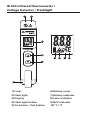
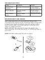
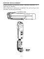
IR-500
Infrared Thermometer /
Voltage Detector /
Flashlight
Users Manual
• Mode d’emploi
• Bedienungshandbuch
• Manual d’Uso
• Manual de uso
Infrared Thermometer /
Voltage Detector /
Flashlight
Users Manual
June 2011, Rev.1
©2011 Amprobe Test Tools.
All rights reserved. Printed in Taiwan
English
IR-500
Limited Warranty and Limitation of Liability
Your Amprobe product will be free from defects in material and
workmanship for 1 year from the date of purchase, unless local laws
require otherwise. This warranty does not cover fuses, disposable
batteries or damage from accident, neglect, misuse, alteration,
contamination, or abnormal conditions of operation or handling.
Resellers are not authorized to extend any other warranty on
Amprobe’s behalf. To obtain service during the warranty period,
return the product with proof of purchase to an authorized
Amprobe Test Tools Service Center or to an Amprobe dealer or
distributor. See Repair Section for details. THIS WARRANTY IS YOUR
ONLY REMEDY. ALL OTHER WARRANTIES - WHETHER EXPRESS,
IMPLIED OR STAUTORY - INCLUDING IMPLIED WARRANTIES OF
FITNESS FOR A PARTICULAR PURPOSE OR MERCHANTABILITY, ARE
HEREBY DISCLAIMED. MANUFACTURER SHALL NOT BE LIABLE
FOR ANY SPECIAL, INDIRECT, INCIDENTAL OR CONSEQUENTIAL
DAMAGES OR LOSSES, ARISING FROM ANY CAUSE OR THEORY.
Since some states or countries do not allow the exclusion or
limitation of an implied warranty or of incidental or consequential
damages, this limitation of liability may not apply to you.
Repair
All test tools returned for warranty or non-warranty repair or
for calibration should be accompanied by the following: your
name, company’s name, address, telephone number, and proof of
purchase. Additionally, please include a brief description of the
problem or the service requested and include the test leads with
the meter. Non-warranty repair or replacement charges should be
remitted in the form of a check, a money order, credit card with
expiration date, or a purchase order made payable to Amprobe®
Test Tools.
In-Warranty Repairs and Replacement – All Countries
Please read the warranty statement and check your battery before
requesting repair. During the warranty period any defective test
tool can be returned to your Amprobe® Test Tools distributor for
an exchange for the same or like product. Please check the “Where
to Buy” section on www.amprobe.com for a list of distributors near
you. Additionally, in the United States and Canada In-Warranty
repair and replacement units can also be sent to a Amprobe® Test
Tools Service Center (see address next page).
Non-Warranty Repairs and Replacement – US and Canada
Non-warranty repairs in the United States and Canada should be
sent to a Amprobe® Test Tools Service Center. Call Amprobe® Test
Tools or inquire at your point of purchase for current repair and
replacement rates.
In USA Amprobe Test Tools Everett, WA 98203 Tel: 877-AMPROBE (267-7623) In Canada
Amprobe Test Tools
Mississauga, ON L4Z 1X9
Tel: 905-890-7600
Non-Warranty Repairs and Replacement – Europe
European non-warranty units can be replaced by your Amprobe®
Test Tools distributor for a nominalv charge. Please check the
“Where to Buy” section on www.amprobe.com for a list of
distributors near you.
European Correspondence Address*
Amprobe® Test Tools Europe
Beha-Amprobe GmbH
In den Engematten 14
79286 Glottertal, Germany
Tel.: +49 (0) 7684 8009 - 0
www.amprobe.eu
*(Correspondence only – no repair or replacement available from
this address. European customers please contact your distributor.)
IR-500 Infrared Thermometer /
Voltage Detector / Flashlight
1
2
3
4
7
8
9 10
5
6
1) Laser
6) Battery cover
2) Flash light
7) Battery indicator
3) Display
8) Laser indicator
4) Flash light button
9) NCV indicator
5) On button / Test button
10) OC / OF
CONTENTS
SYMBOLS............................................................................. 1
UNPACKING AND INSPECTION........................................... 2
INTRODUCTION................................................................... 2
OPERATING INSTRUCTIONS................................................ 3
Power On / Off................................................................ 3
Auto Power Off............................................................... 3
Auto Hold........................................................................ 3
Operating the unit.......................................................... 3
Making Temperature Measurement.............................. 4
°C / °F Selection............................................................... 5
Distance & Spot Size....................................................... 5
Reminders........................................................................ 6
Emissivity......................................................................... 7
Non-Contact Voltage...................................................... 8
SPECIFICATION..................................................................... 9
TROUBLE SHOOTING........................................................... 10
MAINTENANCE AND REPAIR.............................................. 10
BATTERY REPLACEMENT..................................................... 11
SYMBOLS
�
Caution! Refer to the explanation in this Manual
*
Laser light. Do not stare into laser beam
KY
Caution ! Non-contact voltage
M
Battery
Do not apply directly or around bare hazardous
live conductor.
�
Conform to relevant Australian standards
�
Complies with European Directives
=
Do not dispose of this product as unsorted
municipal waste. Contact a qualified recycler
�Safety Information
�Warning
• Do not stare into laser beam.
• Do not point laser directly at eye or indirectly off
reflective surfaces.
• For use by competent persons only.
• Do not leave the unit on or near objects of high
temperature.
• Non-Contact Voltage function can only test on
insulated wires. Testing on high voltage wires
should keep a distance of 20mm minimum.
• Do not use the unit to sense wire voltage higher
than 600V.
1
�Cautions
Use this unit only as specified in this manual or the
protection provided by the unit may be impaired.
The unit should be protected from the following,
• EMF (electro-magnetic fields) from arc welders,
induction heaters
• Static electricity
• Thermal shock (caused by large or abrupt ambient
temperature changes - allow 30 minutes for unit to
stabilize before use)
Unpacking and Inspection
Your shipping carton should include:
1 IR-500
1 1.5V AAA alkaline battery (installed)
1 Manual
If any of the items are damaged or missing, return
the complete package to the place of purchase for an
exchange.
INTRODUCTION
A must-have tool for everyday applications, verify
temperature, voltage presence and use it as flash light
in dark places. Compact and easy to use - just aim, press
the button, and read surface temperatures in less than a
second. You can safely measure surface temperatures of
hot, hazardous, or hard-to-reach objects without contact.
Features
• IR temperature measurement with laser pointer
• Integrated non-contact AC voltage warning
2
• Holds temperature reading for 10 seconds
• Ultra white LED flashlight
• Selectable oF / oC
• Pocket clip
OPERATING INSTRUCTIONS
Power On / Off
press
Auto Power Off
3 minutes.
Auto Hold
The unit will hold the reading for 10 sec after On button
is released.
Operating the Unit
To measure a temperature, point unit at object and press
the Test Button. Be sure to consider distance-to-spot size
ratio and field of view. The unit is equipped with a laser,
use the laser only for aiming. See “Making Temperature
Measurement”.
3
Making Temperature Measurement
Target Area
Incorrect
Make sure that the target is larger than the unit‘s spot
size. The smaller the target, the closer you should be
to it. The minimum measurement area is 3.75cm (1.5in)
diameter.
Press the
key, the unit will show the temperature
key, the LCD will
of target surface. Then release the
hold the reading for 10 seconds.
Press the
key for 3 seconds, the unit will turn into
the IR temperature continuous measurement mode.
4
°C / °F Selection
Press Test button and Flash light button for 2 sec at the
same time for switching temperature unit °C/°F .
Distance & Spot Size
As the distance (D) from the object increases, the spot
size (S) of the area measured by the unit becomes larger.
Use the unit at around 30cm to get the best measurement
accuracy.
At longer distances, the target area shall be larger than
the distance divided by 8.
Please do not put the fingers on the housing for long
period of time and cross the “B line” to prevent from
thermo effect interference of measuring accuracy.
5
Reminders
1. Changes of surrounding ambient temperature
can result in inaccurate reading, allow time for
the unit to adopt the change of ambient before
use. Specified accuracy applies after 30 minutes
when the unit changes to a different environment
ambient.
Allow time for the unit to adopt the change of
ambient from the user’s pocket to enviroment
ambient.
6
2. The unit cannot measure through transparent
surfaces such as glass. Remove the barrier between
the unit and the target surface.
3. Not recommended for use in measuring shiny or
polished metal surfaces (stainless steel, aluminum,
etc.). See Emissivity.
4. Steam, dust, smoke, etc., can prevent accurate
measurement by obstructing the unit‘s optics
Emissivity
Most organic materials and painted or oxidized surfaces
have an emissivity of 0.95 (pre-set in the unit). Inaccurate
readings will result from measuring shiny or polished
metal surfaces. To compensate, cover the surface to be
measured with masking tape or flat black paint. Allow
time for the tape to reach the same temperature as the
material underneath it. Measure the temperature of the
tape or painted surface.
7
Non-Contact Voltage
The Non-Contact Voltage function is ON automatically
when the unit in standby mode.
When Non-Contact Voltage is sensed, the LCD flashes
three dashes and flash light flashes.
The number of dashes displaying on LCD indicates the
electric field intensity. The higher electric field is sensed,
the more “-” symbols display on LCD.
Non-Contact Voltage function can only test on insulated
wires. Testing on high voltage wires should keep a
distance of 20mm minimum.
8
SPECIFICATION
Temperature
Range
-30°C to 500°C (-22°F to 932°F)
Accuracy at
23°C ±2°C
<80﹪RH
-30°C to 0°C (-22°F to 32°F): ±2°C (±4°F)
1°C to 10°C (34°F to 50°F): ±1.5°C (±3°F)
11°C to 40°C (52°F to 104°F): ±1°C (±2°F)
41°C to 500°C (106°F to 932°F): ±1.5°C
(±3°F) or ±1.5% of reading, whichever
is greater.
Best display
Resolution
0.2°C (0.5°F)
Response
Time
0.5 s
Wavelength
6.5um to 18um
Emissivity
E=0.95
D:S
8:1(calculated at 80% energy)
Repeatability
±1°C or ±0.5% of reading, whichever is
greater.
Display Hold
10 s
Non-Contact
Voltage
60VAC ~ 600VAC
Power
1.5V AAA alkaline battery
Weight
Approx. 50g (0.11lb)
Dimensions
(HxWxD)
100 x 20 x 29mm (3.94 x 0.79 x 1.14in)
Storage
Temperature
-20°C to 60°C (without battery)
CE Certification
This instrument conforms to the following standards:
• EN 61326-1 Electromagnetic Emissions and
Susceptibility
• EN 61010-1 General Safety
• EN 60825-1 Laser Safety
9
TROUBLESHOOTING
Code
Problem
Battery icon
appears
Possible low battery Check and/or
replace battery
Action
Blank display
Possible dead
battery
Check and/or
replace battery
Laser doesn‘t
work
Low or dead
battery
Replace battery
MAINTENANCE AND REPAIR
Lens Cleaning: Blow off loose particles using clean
compressed air. Gently brush remaining debris away with
a camel’s hair brush. Carefully wipe the surface with a
moist cotton swab. The swab may be moistened with
water or rubbing alcohol.
NOTE: DO NOT use solvents to clean the plastic lens.
Case Cleaning: Use soap and water on a damp sponge or
soft cloth.
NOTE: DO NOT submerge the unit in water.
10
BATTERY REPLACEMENT
Please replace the battery when “Battery indicator” is
flashing on display.
When battery is replaced / installed, the unit will go into
standby mode automatically
11