1
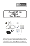
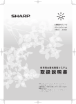
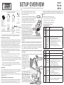
SETUP OVERVIEW
zBoost®
PRO 10K
ZBC745
You can also download the ZBC745 User Manual at www.zBoost.com/Support
Coax Cable
RG-6, 15 ft
Hardware Kit
Indoor Antenna
and TNC-F adaptor
PCS Directional
External Antenna
Dual band outdoor
PCS and CEL
combiner
CEL Directional
External Antenna
SETTING UP YOUR zBOOST® SIGNAL BOOSTER
FIRST: Install the External Antennas
Choosing the best location for installation of the External Antennas provides the best
performance and the largest area of improved signal. Determine the location which
provides the strongest signal using the signal strength indicator on your cell phone.
Find the location which provides the most bars of signal strength and place the
External Antennas at that location. This location will be typically found on the roof.
The YX699 Signal Meter (available separately) provides signal strength information. It
can be used with its supplied whip antenna to find the best location for antenna
placement. It can also identify peak antenna alignment when connected directly to
antenna using the provided cable.
Caution: Avoid placing the External Antennas near metal such as wiring, A/C ducts,
truss plates, etc. When attaching the cable to the External Antenna, run the cable
straight down from the antenna. Avoid draping the coax near the antenna.
When you have determined the location of the strongest signal, install the External
Antennas to a mast or pole (not provided). Loosely secure the antennas to the mast
to allow the antenna to be reoriented for strongest signal.
Connect the coax from the CEL antenna to the connection on the Combiner
marked CEL. Connect the supplied 18” coaxial jumper from the PCS Panel antenna
to the other Combiner port marked PCS.
Antenna Aiming
To get the maximum benefit, you will want to take special care to make sure you point
the antennas in the direction of the best signal for your wireless service provider. See
the User Manual for detailed antenna aiming instructions or visit
www.zBoost.com/Support/install-tips. You may wish to use a YX699 RF signal meter to
help during this process.
SECOND: Install the Base Unit and Indoor Antenna
The Base Unit can be easily mounted on a wall by first removing the bracket from the
Base Unit and using the provided mounting hardware to affix to wall. Connect the
Indoor Antenna to the 15 feet of RG-6. Then, using the TNC-F Adaptor, connect the
The zBoost ZBC745 requires at least 15 feet of vertical separation between the
Indoor Antenna and the External Antennas. Generally, increasing this distance (up to
40 feet) will increase the performance and decreasing the distance will limit zBoost
performance.
THIRD: Run the Coaxial Cable between the External Antennas and the Base Unit
Connect the 50’ coax cable to the Combiner then run the coax cable to the location of
the Base Unit. The recommended maximum cable length run for RG-6 is 60' and 120' for
RG-11. It is highly recommended that you refrain from securing your cable, drilling any
holes, etc. until you complete and test the installation of the Base Unit.
FOURTH: Connect the zBoost Base Unit to the provided power supply and plug into
a power outlet
When your zBoost system is in place and fully connected, walk throughout your building
and verify that you are able to
reliably place calls. If the signal
External Antennas
strength has improved, your
zBoost is working. Remember,
coverage varies based on outdoor
signal level, building construction,
and antenna placement. Coverage
in adjoining rooms (next to, above,
15 ft of
or below) will be reduced by walls
Coax Cable
vertical
and ceiling/floors.
Upon initial power up, the LED will
cycle
RED,
GREEN
and
ORANGE for 30 seconds. After, a
series of GREEN flashes will
indicate the quality of your setup.
Following this, a solid GREEN
light indicates normal conditions.
If it is not solid GREEN, follow the
instructions in the Base Unit LED
separation
Indoor Antenna
Base Unit
Power Supply
1) Move and/or adjust the angle of the Indoor Antenna.
2) Move the External Antenna to a higher location.
See LED Indicator section for more information.
Base Unit LED Indicators
During Initial Power Up
Light Status
Solution
Mode
Cycle
RED,
GREEN,
ORANGE
System is
powering
up. Please
allow up to
30 seconds.
Flashing BASE UNIT will
GREEN flash GREEN
once for every
2 dB less than
optimal system
gain. Three
flashes or less
indicates the
system will
still operate
properly.
N/A
1. Unplug the BASE UNIT power supply.
2. Relocate the EXTERNAL ANTENNA to pick up the
strongest signal from your wireless carrier.
3. Move the EXTERNAL ANTENNA as far away from the
INDOOR ANTENNA as possible, with at least 15 ft. of
vertical separation (height difference).
4. Plug the BASE UNIT power supply back in.
5. Wait 30 secs. for the BASE UNIT to power cycle on.
Solution #1
zBoost Base Unit
Coax Cable
RG-6, 50 ft
Indoor Antenna
The Indoor Antenna should be mounted on a wall facing the
direction where increased coverage is desired. Note that signal
is broadcast in a beamwidth of 70° horizontally and 60°
RG-6 (15 ft)
vertically from the front of the Indoor Antenna. Keep the Indoor
Antenna off floor and at least 3 feet away from other cords,
TNC-F Adaptor
metal objects or other wireless devices such as
zBoost Base Unit
wireless routers or wireless access points. The
zBoost performs best when there are no
Coaxial Cable
obstructions between the Indoor Antenna and
your mobile device. *The FCC requires that
this panel antenna has a minimum horizontal
separation of 6 feet (2 meters) from other CMRS
Power Supply
(commercial mobile radio service) devices.
After Initial Power Up
Light Status
Solution
Mode
SOLID
GREEN
Flashing
GREEN
SOLID
ORANGE
zBoost is
ready.
zBoost is
in use.
EXTERNAL
ANTENNA
and INDOOR
ANTENNA
are too close
together.
N/A
N/A
1. Unplug the BASE UNIT power supply.
2. Move the EXTERNAL ANTENNA as far away from the
INDOOR ANTENNA as possible, with at least 15 ft. of
vertical separation (height difference).
3. Plug the BASE UNIT power supply back in.
4. Wait 30 secs. for the BASE UNIT to power cycle on.
SOLID
Signal from the 1. Unplug the BASE UNIT power supply.
RED
carrier’s cell
2. Relocate the EXTERNAL ANTENNA to another spot.
tower is too
strong for the 3. If you have a directional antenna re-aim it to reduce
carrier signal strength.
BASE UNIT
to operate
4. Plug the BASE UNIT power supply back in.
properly.
5. Wait 30 secs. for the BASE UNIT to power cycle on.
Flashing Excessive
^ Refer to Solution #2
RED
electronic
noise in the
system – the NOTE: Ensure that the EXTERNAL ANTENNAS are not aimed
BASE UNIT will at metal surfaces. This is a common problem
not operate.
Solution #2
Power Supply
Indicators section. Adjustments may be needed to optimize performance. If you find
the increased signal coverage is acceptable, however, no additional adjustments are
needed.
Should you desire to improve coverage, you may:
Solution #3
RG-6 to the Base Unit. The Base Unit should be a minimum
distance of 4-5 feet off from the floor so there is clearance for
the Indoor Antenna extension.
PACKAGE CONTENTS
DMAN-0076 Rev 4914
zBoost PRO 10K ZBC745 Technical Specifications
Warranty Information
PCS
CEL
Frequency
1850 - 1990 MHz
824 - 894 MHz
System Gain
84 dB
75 dB
Bands Supported
ALL: A,D,B,E,F & C
ALL: A,B, A’ & B’
zBoost warrants every zBoost product to be free from defects in material and workmanship under normal use for the warranty period of 2 years.
Output Power
Uplink: 19 dBm; Downlink: 4 dBm
Uplink: 21 dBm; Downlink: 4 dBm
Who Is Covered?
Networks Supported
CDMA, GSM, TDMA, GPRS, EDGE, EVDO, HSPA, 3G
Wall Supply Input; Voltage
100-240VAC 50-60 Hz
Power Consumption
3W standby; 7W max signal - 2.0A Max
You must have proof of purchase to receive warranty service. A sales receipt or other documentation showing the product purchased and
the purchase date is considered proof of purchase. This limited warranty extends only to the original consumer purchaser or any person
receiving the product as a gift from the original consumer purchaser and to no other purchaser or transferee.
TNC Connector: 50 Ohm; F Connector: 75 Ohm
What is Covered?
Input and Output Impedance
FCC Parts 15 & 20, Industry Canada
Base Unit Size and Weight
5” x 7” x 1.25” - 9 oz.
Base Unit and Power Supply
Indoor Use Only, 40° to 105° F
Coverage (open areas)
10,000 sq. ft.
The manufacturer’s rated output power of this equipment is for single carrier operation. For situations when multiple carrier signals are present,
the rating would have to be reduced by 3.5 dB, especially where the output signal is re-radiated and can cause interference to adjacent band
users. This power reduction is to be by means of input power or gain reduction and not by an attenuator at the output of the device.
This product uses patented technology to protect the carrier network.
FCC Requirement
This is a CONSUMER device.
BEFORE USE, you MUST REGISTER THIS DEVICE with your wireless provider and have your provider’s consent. Most wireless providers consent to the use of signal
boosters. AT&T, Sprint, T-Mobile, Verizon and 90 additional carriers have already given consent for all consumers to use this device. Some providers may not consent to the
use of this device on their network. If you are unsure, contact your provider.
You MUST operate this device with approved antennas and cables as specified by the manufacturer. Antennas MUST be installed at least 20 cm (8 inches) from any person.
You MUST cease operating this device immediately if requested by the FCC or a licensed wireless service provider.
WARNING. E911 location information may not be provided or may be inaccurate for calls served by using this device.
FCC contact information: www.fcc.gov/signal-boosters/registration.
FCC Information
FCC ID: SO4ZB570-PCS-CEL
Warning: Changes or modifications to this device not expressly approved by zBoost could void the user’s authority to operate the equipment.
Note: This equipment has been tested and found to comply with the limits for a Class B digital device, pursuant to Part 15 of the FCC Rules. These limits are designed to
provide reasonable protection against harmful interference in a residential installation. This equipment generates, uses, and can radiate radio frequency energy and, if not
installed and used in accordance with the instructions, may cause harmful interference to radio communications. However, there is no guarantee that interference will not
occur in a particular installation. If the equipment does cause harmful interference to radio or television reception, which can be determined by turning the equipment off and
on, the user is encouraged to try to correct the interference by one or more of the following measures:
• Reorient or relocate the receiving antenna
• Increase the separation between the equipment and receiver
• Connect the equipment to an outlet on a circuit different from that to which the receiver is connected
• Consult the dealer or an experienced radio/TV technician for help
This equipment complies with FCC radiation exposure limits set forth for an uncontrolled environment. This transmitter must not be co-located or operating in conjunction
with any other antenna or transmitter. In accordance with FCC requirements of human exposure to radiofrequency fields, the radiating element (antenna) shall be installed
such that a minimum separation distance of 20cm (8in) is maintained from all persons.
Industry Canada Regulations
Canada IC: 5544A-ZB570PCSCEL
This Class B digital apparatus meets all requirements of the Canadian Interference Causing Equipment Regulations. Operation is subject to the following two conditions: (1)
this device may not cause harmful interference, and (2) this device must accept any interference received, including interference that may cause undesired operation.
The term “IC:” before the radio certification number only signifies that Industry Canada technical specifications were met.
RF Exposure:
The manufacturer’s rated output power of this equipment is for single carrier operation. For situations when multiple carrier signals are present, the rating would have to be
reduced by 3.5 dB, especially where the output is re-radiated and can cause interference to adjacent band users. This power reduction is to be by means of input power or
gain reduction and not by an attenuator at the output of the device.
Please note: This unit has been approved for use in Canada under RSS 131, however, consent for the use of this device to improve cellular or PCS coverage, must be
obtained through your cellular or PCS provider, prior to placing the unit in operation. Please refer to the Industry Canada document CPC 2-1-05, Section 6.1 available or
viewable at: http://www.ic.gc.ca/epic/site/smt-gst.nsf/en/sf08942e.html
Cet appareillage numérique de la classe [B] répond à toutes les exigences de l’interférence canadienne causant des règlements d’équipement. L’opération est sujette aux
deux conditions suivantes: (1) ce dispositif peut ne pas causer l’interférence nocive, et (2) ce dispositif doit accepter n’importe quelle interférence reçue, y compris
l’interférence qui peut causer l’opération peu désirée.
Le fabricant nominale de la puissance de sortie de ce matériel est simple transporteur. Pour les situations lorsque plusieurs signaux porteurs sont présents, l’évaluation
devrait être réduite de 3.5 dB, en particulier lorsque le signal de sortie est ré-émise et peut provoquer des interférences adjacentes à la bande utilisateurs. Ce pouvoir est de
la réduction par le biais de la sortie d’alimentation ou la réduction de gain et non par un atténuateur à la sortie du dispositif.
LIMITED 2 YEAR MANUFACTURER WARRANTY | WARRANTY REGISTRATION AT WWW.ZBOOST.COM
Warranty coverage begins the day you purchase the product. For one year from the original date, the zBoost Cell Phone Signal Booster will
be repaired or replaced with a new, repaired, refurbished or comparable product (whichever is deemed necessary by zBoost) if it becomes
defective or inoperative. The exchange will be made without charge to you for parts and labor. You will be responsible for the cost of shipping
to the location designated by zBoost. If zBoost cannot reasonably repair or replace the unit then zBoost may, at its sole discretion, refund
the price you paid for the product or the price of the unit. All products, including replacement products, are covered only for the original
warranty period. When the warranty on the original product expires, the warranty on the replacement product also expires.
What is Excluded?
Your warranty does NOT cover:
• Labor charges for set up of the unit.
• Product replacement because of misuse, accident, lightning damage, unauthorized repair or other cause not within the control of zBoost.
• Incidental or consequential damages resulting from the product. Some states do not allow the exclusion of incidental or consequential
damages, so the above exclusion may not apply to you.
• Any modifications or other changes to the product, including but not limited to software or hardware modifications in any way other
than as expressly authorized by zBoost will void this limited warranty.
• Product that has been modified or adapted to enable it to operate in any country other than the country for which it was designed,
manufactured, approved and/or authorized, or repair of products damaged by these modifications.
All zBoost products that are packaged with other zBoost accessory products are intended for resale and use as a single unit, and such
product kits are required to be sold to the end user or subsequent reseller as packaged. The “de-kitting” and sale as a standalone product
of any one or more components of such a product kit is in violation of zBoost’ warranty. No “de-kitted” product will be eligible for return for
any reason. The sale of separate, not-kitted cable, antennas and other accessories is allowed and fully warranted
Make sure you keep…
Please keep your sales receipt or other document showing proof of purchase. Attach it to this Setup Overview and keep both nearby. Also,
keep the original box and packing material in case you need to return your product.
Before requesting repair service…
Please see the BASE UNIT LED INDICATORS section listed in this overview for troubleshooting.
To get warranty service…
Warranty service will be provided by zBoost. If you need service for your unit, contact us at 1-800-871-1612 or [email protected]. A
representative will go through a diagnostic checklist with you. If the product needs to be returned for service or exchanged, you will receive
a return merchandise authorization (RMA) number. The representative will give you complete shipping details. Please do not return products
to zBoost without an RMA.
To get out of warranty service…
To obtain out of warranty service, contact zBoost at 1-800-871-1612 or [email protected] for information on the possibility of any costs
for repair or replacement of out-of-warranty products.
Reminder: Record the model and serial number found on the product:
Model #:
Serial #:
Purchase Date:
Customer Support
The complete zBoost ZBC745 Manual and additional product information is available at
www.zBoost.com/Support.
For questions or assistance, contact zBoost Customer Care at 1-800-871-1612 or email
[email protected].