1
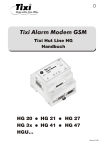
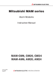
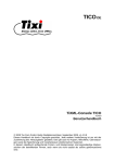
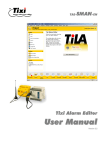
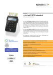
쐌
Anschluss Mitsubishi Alpha XL und Mitsubishi FX an RS232 und RS485/422
Anschlüsse
MITSUBISHI ELECTRIC
Alpha XL
쐌 direkt mit dem Kabel „AL2-GSM-CAB“ an COM1 des MAM
쐌 mit dem Kabel „AL2-GSM-CAB“ und dem „Red Adapter“ an COM2 des MAM
Mitsubishi Alarm Modem GSM
Installationsanleitung
MAM-GM6
MAM-GM20
MAM-GM24
Mitsubishi FX1S, FX1N, FX2N und FX2NC
쐌 an dem RS232-BD der FX: mit einem seriellen Kabel (1:1) und dem “Brown Adapter” an COM1
쐌 an dem RS232-BD der FX: mit einem seriellen Kabel (1:1) und dem „Red Adapter“ an COM2
쐌 der RS 485-BD / 422-BD der FX ist mit dem RS485/422-Anschluss wie folgt zu verdrahten:
SDA=R+, SDB=R-, RDB=T, RDA=+T, SG=oV
na
n
nte
A
de
m
de
Mo
ou
541034
Service Taster
für Kundenfunktion
ss
ce
Pro
sh
Pu
A
mlar
m
1 it2
0 x M
- Ro
3 s d
0 2 e
V 32m
D +G
S
C
, 6 M
m I/
a O
x. s
0
.7
er
w
Po
Alarm Modem GSM
t
ta
Da
e
Lin
e
rvic
Se
mit2x Rs232 + 6 I/Os
10 - 30 V DC, max. 0.7 A
027954
Mo
Antenna
ard
Service
-C
SIM
)
32
S2
A
10...30 V DC
Spannungsversorgung
(Buchse) über externes
Netzteil
(R
M1
0
2
CO
7
9
5
4
5
4
1
0
3
4
)
32
M2
S2
(R
Power
Process
CO
0V
10
Line
SIM-Card
...3
DC
Stecker (FME) für das
Antennenkabel
(Impedanz: 50 Ω)
-
+
+
COM2 (RS232)
Data out
Modem Mode
Push
COM1 (RS232)
-
10...30 V DC
Spannungsversorgung
(2 Schraubklemmen)
Sicherheitshinweise
COM2 (RS232) 9-poliger D-SUB-Stecker
COM2 RS485/422 5pol.Schraubklemme
(nur MAM-AM24)
COM1 (RS232)
9-polige D-SUB-Buchse
Zielgruppe Elektrofachkräfte
Diese Installationsanleitung richtet sich ausschließlich an anerkannt ausgebildete Elektrofachkräfte, die mit den Sicherheitsstandards der Elektro- und Automatisierungstechnik vertraut sind. Projektierung, Installation, Inbetriebnahme, Wartung und Prüfung der Geräte dürfen nur von einer anerkannt ausgebildeten Elektrofachkraft durchgeführt werden. Eingriffe
in die Hard- und Software unserer Produkte, soweit sie nicht in dieser Installationsanleitung oder anderen Handbüchern
beschrieben sind, dürfen nur durch Fachpersonal vorgenommen werden.
Bedeutung der LEDs
LED
Status
An
Aus
An
Aus
An
Aus
An blinkt 1x
An blinkt
An
Aus
Power (gelb)
Process (rot)
Bestimmungsgemäßer Gebrauch
Die Mitsubishi Alarm Modems sind nur für die Einsatzbereiche vorgesehen, die in der vorliegenden Installationsanleitung
beschrieben sind. Achten Sie auf die Einhaltung aller in der Installationsanleitung angegebenen Kenndaten. Unqualifizierte Eingriffe in die Hard- oder Software bzw. Nichtbeachtung der in dieser Installationsanleitung angegebenen oder am
Produkt angebrachten Warnhinweise können zu schweren Personen- oder Sachschäden führen. In solchen Fällen wird
keine Haftung übernommen und es erlischt jeder Garantieanspruch.
Line (grün)
Data Out (gelb)
Aus
Sicherheitsrelevante Vorschriften
Bei der Projektierung, Installation, Inbetriebnahme, Wartung und Prüfung der Geräte müssen die für den spezifischen Einsatzfall gültigen Sicherheits- und Unfallverhütungsvorschriften beachtet werden.
In dieser Installationsanleitung befinden sich Hinweise, die für den sachgerechten und sicheren Umgang mit dem Gerät
wichtig sind. Die einzelnen Hinweise haben folgende Bedeutung:
E
ACHTUNG:
Bedeutet eine Warnung vor möglichen Beschädigungen des Gerätes, der Software oder
anderen Sachwerten, wenn die entsprechenden Vorsichtsmaßnahmen nicht getroffen
werden.
Modem Mode (rot)
An
An
Stellen Sie nach Durchführung aller anderen Installationsarbeiten den Anschluss der Spannungsversorgung zum
Mitsubishi Alarm Modem her. Das Gerät hat zwei Stromversorgungsanschlüsse, zum einen über zwei Schraubklemmen und zum anderen über eine Netzgeräte-Einbaukupplung (Stiftdurchmesser = 2 mm, Innendurchmesser = 6 mm).
E
ACHTUNG:
Spannung U = 10 – 30 V DC!
Achten Sie auf die korrekte Polarität der Spannungsanschlüsse.
P
GEFAHR:
쎲 Verwenden Sie zum Anschluss nur Leitungen mit ausreichendem Leitungsquerschnitt.
쎲 Setzen Sie keine flexible Leitung mit verlöteten Kabelenden ein.
쎲 Beachten Sie die korrekte Polarität der Spannungsanschlüsse und Kenndaten
(10 – 30 V DC, max. 0,7 A, bei Netzgeräte-Einbaukupplung: Stift = Pluspol)
쎲 Um Beschädigungen zu vermeiden, drehen Sie die Klemmschrauben mit einem Drehmoment von 0,5–0,6 Nm fest.
쎲 Nutzen Sie die Netzgeräte-Einbaukupplung, vergewissern Sie sich, dass der Stecker
einen Innendurchmesser von 2,1 mm und einen Außendurchmesser von 6 mm hat.
쎲 Das Gerät darf nur im spannungslosen Zustand verdrahtet werden.
Inbetriebnahme
Power (gelb)
An
An
An
An
Process (rot)
Line (grün)
An
An
Data Out (gelb)
An
An
An blinkt
Modem Mode (rot)
An
Start Selbsttest
Test aller LEDs
Speichertest
MAM ist betriebsbereit.
Dauer Selbsttests
ca. 12 s
Einbau
Montieren Sie das MAM durch Aufschieben oder Aufschnappen auf einer DIN-Schiene (Hutschiene 35 mm).
Ziehen Sie die schwarze Lasche am Gerät mit einem Schraubendreher etwas heraus, damit das Gerät auf die Hutschiene
aufschnappen kann. Auf die gleiche Weise können Sie es auch
wieder von der Hutschiene entfernen. Achten Sie darauf, dass
die Arretierung des Modems sauber in die Hutschiene einschnappt.
a
tenn
An
de
Mo
dem
Mo
ta
out
Da
e
Lin
s
rvice
ces
Se
Pro
h
Pus
Ti
xxxi
xxxxAlar
- x Xxm
xx
M
X xx od
x
XX
+ em
, X
xx xxG
x. x SM
X.
X
X
P
Funktion
Gerät betriebsbereit
Keine Stromversorgung
Prozessabarbeitung: Nachrichtengenerierung, Variablenänderung, Schalten
Normalbetrieb, es wird kein Prozess ausgeführt.
GSM-Verbindung besteht.
Modem ist nicht im GSM-Netz eingebucht.
Modem ist im GSM-Netz eingebucht. (LED blinkt alle 2 s.)
Ein- oder abgehender Ruf: Verbindungsaufbau (LED blinkt 4-mal pro Sekunde.)
Nachrichten zum Versand im Gerät
Keine Nachrichten im Postausgang
TiXML-Modus
Standard-Modus für das Mitsubishi Alarm Modem
Modem-Modus
Gerät kann über COM1 lokal als Standard-Modem genutzt werden.
Transparent-Modus (Gerät hat transparente Verbindung durchgeschaltet)
Stromversorgung
er
Pow
rd
-Ca
SIM
)
85
S4
02
GEFAHR:
Bedeutet, dass eine Gefahr für das Leben und die Gesundheit des Anwenders besteht,
wenn die entsprechenden Vorsichtsmaßnahmen nicht getroffen werden.
M1
79
Bu
54
(0V)
10
34
-T
R-
M2
10.
g.
nfi
Co
5)
/ 48
S4
V
..30
DC
+T
22
R+
(R
CO
s
54
(R
CO
+
-
SPS-Treiber im Mitsubishi Alarm Modem
Die Mitsubishi Alarm Modems können mit den jeweiligen speicherprogrammierbaren Steuerungen über deren interne Protokolle kommunizieren, ohne dass ein Programm, Treiber oder Funktionsblock in die Steuerung geladen werden muss. Sie
haben damit direkten Zugriff auf alle Variablen, Merker und Ein-/Ausgänge der Steuerungen.
Mit Hilfe der optionalen Bediensoftware MX Mitsubishi Alarm Editor kann das Alarm Modem leicht parametriert werden.
Folgende Steuerungen werden unterstützt: Alpha XL und MELSEC FX1S/1N, FX2N/2NC
Zur Kommunikation zwischen einem MAM und der SPS steht zusätzlich das international gängige Feldbus-System Modbus (ASCII und RTU) zur Verfügung.
Serielle Schnittstellen
Merkmal
Weitere Informationen zur Bedienung der Modems finden Sie unter www.mitsubishi-automation.de
Modelle
Die Mitsubishi Alarm Modems für GSM der GM-Serie sind in den Grundfunktionen identisch. Sie unterscheiden sich jedoch
in der Art und Anzahl der Schnittstellen.
Schnittstellen
COM1
MAM-GM6
RS232
MAM-GM20
RS232
MAM-GM24
RS232
COM2
—
RS232
RS485/422
E
ACHTUNG:
쎲 Das Gerät darf nur in trockenen und sauberen Räumen eingesetzt werden. Schützen Sie
das Gerät vor Feuchtigkeit, Spritzwasser und Hitzeeinwirkungen und direkter Sonnenbestrahlung.
쎲 Das Gerät darf nicht in Umgebungen eingesetzt werden, in denen entzündliche Gase,
Dämpfe oder Stäube oder leitfähige Stäube vorhanden sind.
쎲 Setzen Sie das Gerät keinen starken Vibrationen aus.
Suchen Sie zunächst einen geeigneten Aufstellplatz für die GSM-Antenne außerhalb des Schaltschrankes. Zur Auffindung
eines geeigneten Standortes mit gutem Empfang können Sie sich mit der Bediensoftware MX Mitsubishi Alarm Editor die
Empfangsqualität anzeigen lassen.
Schrauben Sie den Antennenstecker in die Antennenbuchse an der Frontseite des Modem ein.
Die GSM Antenne befindet sich nicht im Lieferumfang des Modems und muss separat bestellt werden.
71
88
58
13
COM1
COM2
RS485/422
COM2
Allgemeine Daten
GSM-Antenne anschließen
Abmessungen
RS232
Daten
Nach ITU-T V.24, V.28, Hardware Handshake
D-Sub 9-polig, Buchse, FIFO 16550, max. 230.400 bps,
Signale: DTR, DSR, RTS, CTS, DCD, GND, RI, RxD, TxD, Übertragungsdistanz: 15 m
D-Sub 9-polig, Stecker, sonst wie bei COM1
Nach EIA/TIA-485
5-poliger Schraubanschluss für T+, T-, R+, R-, 0 V max. 1,5 Mb/s, nicht galvanisch getrennt
Terminierung integriert, zuschaltbar über DIP-Schalter
Übertragungsdistanz max.1200 m in Abhängigkeit von Übertragungsrate, Bussystem und Kabeltyp
ta
Daten
Netz
GSM/GPRS Class 10, Dual Band 900/1800 MHz
FME-Stecker (male), Koaxial, Impedanz 50 Ohm,
Empfangsfrequenz:
925 bis 960 MHz/
1805 bis 1880 MHz
Sendefrequenz:
880 bis 915 MHz/
1710 bis 1785 MHz
Leistung:
2 W (900 MHz)
1 W (1800 MHz)
300 bps – 14,4 kbps async., transparent/nicht transparent
ITU-T (V.21,V.22, V.22bis, V.26ter, V.32, V.34, V.110)
Fax Gruppe 3 / Class 1 und 2, 2400 bps – 14,4 kbps ITU-T (V.17, V.29, V.27ter)
Datenkompression: MNP2, V.42bis
Antenne
Datenübertragung
SIM-Karte einsetzen
Da
Merkmal
Drücken Sie den Knopf, bis die Kartenaufnahme
herausspringt.
t
ou
e
Lin
ss
ce
Pro
Faxübertragung
h
Pus
)
S2
Betrieb
Temperaturbereich
Lagerung
Zulässige Luftfeuchtigkeit
Schutzart
Verschmutzungsgrad
Abmessungen
Daten
10 – 30 V DC, max. 0,7 A, Schraubklemme 2,5 mm² und Netzgeräte-Einbaukupplung
(Stiftdurchmesser = 2 mm, Innendurchmesser = 6 mm).
Power, Process, Line (Verbindung), Data out, Modem Mode
Taster
DIN-Schienen-Gehäuse / auf Hutschiene 35 mm nach EN 50022, senkrecht, waagerecht
, EN 55022 (9:2003), EN 55024 (10:2003) EN 301489-1/7 (2000 GSM) EN 60950
3GPP TS 51.010-1 (9:2002, v5.0.0.0) GCF-CC (10:2002, v3.8.1)
0 bis +50 °C
-30 bis +70 °C
5 bis 95 % relative Feuchte, nicht betauend
IP20
Verschmutzungsgrad 2
Breite: 88 mm x Höhe: 58 mm x Tiefe: 91 mm (ohne Antennenanschluss)
Gewicht
240 g
Spannungsversorgung
32
1
OM
(R
C
46
541034
91
027954
Alarm Modem GSM
mit 2x Rs232 + 6 I/Os
10 - 30 V DC, max. 0.7 A
4
Antenna
Service
Merkmal
ard
-C
SIM
LED-Anzeige
Bedienelemente
Gehäuse/Montage
)
32
S2
(R
M2
CO
0V
..3
+
-
Power
Process Line Data out
SIM-Card
Konformität
Modem Mode
Legen Sie die SIM-Karte mit der Kontaktseite nach oben ein und
achten Sie darauf, dass die Karte exakt in der Aussparung sitzt.
Schieben Sie die Kartenaufnahme mit der SIM-Karte wieder in
das Modem zurück, bis die Kartenaufnahme einrastet.
Die SIM-Karte befindet sich nicht im Lieferumfang des Modems
und muss separat bestellt werden.
Push
a
tenn
An
DC 10...30V
de
m
Mo
de
Mo
t
ta
ou
Da
+
COM2 (RS232)
COM1 (RS232)
Lin
e
e
s
rvic
ces
Se
Pro
H
sh
Pu
G
Ti
mxi
10it2Alar
x
- Rm
30 s2
2
r
7
we
Po
rd
-Ca
M
V 32od
D + em
C,
6 G w
m I/O
ax SM ww.
s
. 0.
tix
i.c
7
om
A
SIM
)
32
M1
02
79
54
S2
(R
CO
54
10
34
)
4,3
-
32
M2
(R
CO
V
..30
DC
S2
Standards
10.
+
ard
-C
SIM
Terminals
MITSUBISHI ELECTRIC
Mitsubishi Alpha XL and Mitsubishi FX at RS232 RS232 and RS485/422
Alpha XL
쐌 directly by the “AL2-GSM-CAB” cable to COM1
쐌 by the “AL2-GSM-CAB” cable and the “Red Adapter” to COM2
Mitsubishi Alarm Modem GSM
Installation Manual
MAM-GM6
MAM-GM20
MAM-GM24
Mitsubishi FX1S, FX1N, FX2N, and FX2NC
쐌 at the RS232-BD of the FX: directly by a serial cable (1:1) to COM1
쐌 at the RS232-BD of the FX: by a serial cable (1:1) and the “Red Adapter” to COM2
쐌 the RS485-BD/422-BD of the FX is to be connected with the RS485/422 interface as follows:
SDA=R+, SDB=R-, RDB=T, RDA=+T, SG=oV
na
n
nte
A
de
m
de
Mo
ou
541034
Service Button
for customer specific
functions
ss
ce
Pro
sh
Pu
A
mlar
m
1 it2
0 x M
- Ro
3 s d
0 2 e
V 32m
D +G
S
C
, 6 M
m I/
a O
x. s
0
.7
er
w
Po
ard
Alarm Modem GSM
t
ta
Da
e
Lin
e
rvic
Se
mit2x Rs232 + 6 I/Os
10 - 30 V DC, max. 0.7 A
027954
Mo
Plug (FME) for Antenna cable
(Impedance: 50Ω)
Antenna
)
32
S2
A
10...30V DC
Power supply (jack) for
external power supply
(R
M1
0
2
CO
7
9
5
4
5
4
1
0
3
4
Power
Process
)
32
M2
S2
...3
DC
10
Data out
Modem Mode
Push
(R
CO
0V
Line
SIM-Card
-
+
+
COM2 (RS232)
COM1 (RS232)
-
10...30V DC
Power supply
(2 screw terminals)
COM2 (RS232) 9pin D-Sub plug
COM2 RS485/422 5-pole screw terminal
(only MAM-GM24)
COM1 (RS232)
9pin D-Sub jack
Security Advice
Intended Target Audience
Meaning of the LEDs
This installation manual is aimed exclusively at suitably qualified electrical engineering specialists that are familiar with the
safety standards required for electrical engineering and automation. The engineering, installation, commissioning, maintenance and testing of devices must only be carried out by qualified electrical technicians. Unless otherwise stated in this
installation manual or other manuals, any intervention in the hardware and software of our products must only be carried
out by specialists.
LED
Status
On
Off
On
Off
On
Off
On flashes 1x
On flashes
On
Off
Power (yellow)
Process (red)
Proper use
Mitsubishi Alarm Modems are only designed for use in the application fields described in this installation manual. Ensure
that all the specifications stated in this installation manual are observed. Unqualified interventions in the hardware or software, and failure to observe the warnings stated in this installation manual or on the product may lead to serious injury or
material damage. No liability is accepted in such cases and any warranty claims become invalid.
Line (green)
Data Out (yellow)
Off
Safety instructions
The safety and accident prevention regulations specified for the application concerned must be observed during the engineering, installation, maintenance and testing of devices.
This installation manual contains special instructions that are important for the safe and proper handling of the device. The
warning symbols of the individual instructions have the following meaning:
E
ATTENTION:
Is a warning of possible damage to the device, software or other material damage if the relevant safety measures are not taken.
Modem Mode (red)
On
On
Funktion
Device operational
No power supply
Processing in progress: message generation, variable changes etc.
Normal Operation, no processing in progress.
GSM connection present.
Modem is not logged onto the GSM network.
Modem is logged onto the GSM network. (LED flashes every 2 s.)
Incoming or outgoing call: Establishing connection (LED flashes 4 times per second.)
Message ready to send waits inside the device.
No message in outbox.
TiXML Mode
Standard mode for the Mitsubishi Alarm Modem.
Modem Mode
Device usable as generic modem via COM1.
Transparent Mode (device provides transparent connection)
E
ATTENTION:
Power U = 10 – 30VDC!
Ensure the correct polarity of the power supply terminals.
P
DANGER:
쎲 Use leads with sufficient diameter only.
쎲 Do not use flexible leads with soldered tips.
쎲 Watch the polarity and currency parameters (10 ... 30 VDC, max. 0.7A,
Power supply jack: pin = positive)
쎲 In order to avoid damage, fasten the terminal screws with a torque momentum of 0.5 ... 0.6 Nm.
쎲 When using the power supply jack, make sure the plug got an inner/outer diameter of
2,1/6mm.
쎲 Wiring must be done with power off only.
Operation
Power (yellow)
Process (red)
Line (green)
Data Out (yellow)
On
On
Modem Mode (red)
On
On
On
On
On flashes
On
On
Starting Self-test
On
Testing LEDs
Testing memory
Modem is fully operational
Duration: approx. 12 sec
Mounting
Mount the modem by pushing or snap fitting it onto a DIN rail (top-hat rail 35mm).
Pull out the black tab on the device using a screwdriver and so
the device can snap fit to the DIN rail. You can remove the
device from the rail in the same way. Ensure that the retaining
machanism of the modem snaps cleanly and securely into the
DIN rail.
a
tenn
An
de
Mo
dem
Mo
ta
out
Da
e
Lin
s
rvice
ces
Se
Pro
h
Pus
Ti
xxxi
xxxxAlar
- x Xxm
xx
M
X xx od
x
XX
+ em
, X
xx xxG
x. x SM
X.
X
X
P
Power supply
After all other installation steps are completed, switch on the power supply to the Mitsubishi Alarm Modem. The modem has
two power supply connectors: two screw terminals and a power supply jack (pin diameter 2mm, inner diameter 6mm).
Service
-C
SIM
er
Pow
rd
-Ca
SIM
)
85
S4
02
M1
79
DANGER:
Means that there is a danger to the life and health of the user if the relevant safety measures are not taken.
Bu
54
10
34
-T
R-
M2
10.
(0V)
g.
nfi
Co
5)
/ 48
S4
V
..30
DC
+T
22
R+
(R
CO
s
54
(R
CO
+
-
PLC driver in the Mitsubishi Alarm Modem
Mitsubishi Alarm Modems can communicate with the relevant PLCs using their internal protocols without having to load a
program, driver or function block into the PLC concerned. They then have direct access to all variables, markers and I/O on
the PLCs. The Alarm Modem can easily be set with parameters using the software MX-Mitsubishi Alarm Editor.
These PLCs are supported:
Alpha XL and MELSEC FX1S/1N, FX2N/2NC
For MAM-PLC communication, the internationally standardized fieldbus system Modbus (ASCII and RTU) may also be
utilized.
Serial interfaces
Interface
For further information about the modems please refer to the Mitsubishi homepage. ( www.mitsubishi-automation.com)
Models
The basic functions of HG series Mitsubishi Alarm Modems are identical. Only the type and number of interfaces vary
according to the model used.
Interfaces
COM1
MAM-GM6
RS232
MAM-GM20
RS232
MAM-GM24
RS232
COM2
—
RS232
RS485/422
E
ATTENTION:
쎲 The device must only be used in rooms that are dry and clean. Protect the device from humidity,
water splashes or heat.
쎲 The device must not be used in environments containing flammable gases, fumes or dust.
쎲 Do not subject the device to severe vibration.
Connecting the GSM antenna
First of all find a suitable location for mounting the GSM antenna outside of the control cabinet. In order to find a suitable
location with a good reception quality you may use the software MX Mitsubishi Alarm Editor to display the signal quality.
Screw the antenna plug into the antenna socket on the front of the modem.
The GSM antenna is not supplied with the modem and has to be ordered separately.
Dimensions
71
88
58
RS232
COM1
COM2
RS485/422
COM2
General Data
Feature
Net
Data
GSM/GPRS Class 10, Dual Band 900/1800 MHz (GSM-Serie)
FME plug (male), coaxial, Impedance: 50 Ohm,
Reception frequency:
925 ... 960 MHz/
1805 ... 1880 MHz
Transmission frequency:
880 ... 915 MHz/
1710 ... 1785 MHz
Output:
2 W (900 MHz)
1 W (1800 MHz)
300 bps – 14,4 kbps async., transparent/nicht transparent
ITU-T (V.21,V.22, V.22bis, V.26ter, V.32, V.34, V.110)
Fax Group 3 / Class 1 and 2. 2400 bps – 14,4 kbps ITU-T (V.17, V.29, V.27ter)
Data compression: MNP2, V.42bis
Antenna
Inserting the SIM card
13
Push down the button until the card holder is released.
t
ta
Da
ou
Data transmission
e
Lin
ss
ce
Pro
Fax transmission
h
Pus
Data
To ITU-T V.24, V.28, Hardware-Handshake
D-Sub 9-pole, Socket, FIFO 16550, max. 230.400bps,
Signals: DTR, DSR, RTS, CTS, DCD, GND, RI, RxD, TxD, Transmission distance: 15m
D-Sub 9-pole, plug, otherwise as for COM1
To EIA/TIA-485
5-pole screw terminal for T+, T-, R+, R-, 0 V
max. 1,5Mb/s, not isolated, Termination integrated, activated via DIP switches
Transmission distance max.1200m depending on the transmission rate, bus system and cable type
ard
-C
SIM
)
32
M1
Feature
+
-
Insert the SIM card with the contact side facing upwards and
ensure that the card is seated correctly in the recess.
Then push the SIM card holder back into the modem until it
snaps into position.
The SIM card is not supplied with the modem and has to be
ordered separately.
a
de
m
Mo
de
Mo
Push
t
ta
ou
Da
e
Lin
e
s
rvic
ces
Se
Ti
sh
Pu
G
2
mxi
10it2Alar
x
- R
r
7
we
Po
COM2 (RS232)
rd
-Ca
SIM
od
D + em
C,
6 G w
m I/O
ax SM ww.
s
. 0.
tix
i.c
7
om
A
COM1 (RS232)
)
32
M1
02
79
54
S2
(R
CO
54
10
34
)
32
M2
S2
(R
CO
V
..30
DC
10.
+
ard
-C
SIM
4,3
+
Pro
H
m
30 s2 M
V 32
-
Weight
240g
0V
..3
Modem Mode
DC 10...30V
Operation
Storage
Permissible air humidity
Degree of protection
Degree of pollution
Dimensions
Power supply
tenn
An
SIM-Card
Data
10 – 30V DC, max. 0.7A, screw terminal 2.5mm² und power supply jack
(pin diameter 2mm, inner diameter 6mm).
Power, Process, Line (connection), Data out, Modem Mode
Button
DIN-Rail Casing, for rail 35mm to EN50022, vertical or horizontal
, EN 55022 (9:2003), EN 55024 (10:2003) EN 301489-1/7 (2000 GSM) EN 60950
3GPP TS 51.010-1 (9:2002, v5.0.0.0) GCF-CC (10:2002, v3.8.1)
0 ... +50°C
-30 ... +70°C
5 to 95% relative humidity, non-condensing
IP20
Pollution degree 2
Width: 88mm x Height: 58mm x Depth: 91mm (without antenna connection)
)
32
S2
2 (R
M
CO
46
541034
Process Line Data out
91
027954
Power
Alarm Modem GSM
mit 2x Rs232 + 6 I/Os
10 - 30 V DC, max. 0.7 A
4
Antenna
Service
S2
(R
CO
LEDs
Operating elements
Housing/mounting
Conformity
Temperaturrange
Standards