1
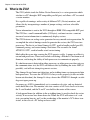
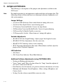
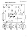
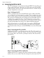
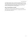
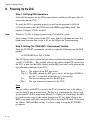
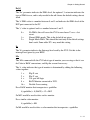
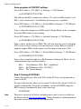
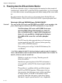
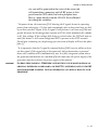
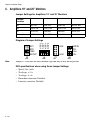
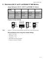
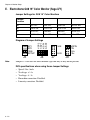
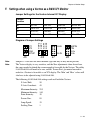
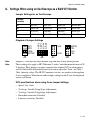
C h a p t e r
1
Overview of the ZVG
A quick overview of the ZVG
• A Short Description of the ZVG.
• ZVG Specifications.
• An Overview of Jumper Setting and Controls.
7/7/06
Rev 0.5
1–1
Chapter 1: Overview of the ZVG
A. What is the ZVG?
The ZVG (which stands for Zektor Vector Generator) is a vector generator which
attaches to a PC through a ECP compatible parallel port, and allows a PC to control
a vector monitor.
It is capable of running a wide variety of different X/Y (Vector) monitors, and
allows this by incorporating a number of jumper settings, and user selectable
parameters.
Vector information is sent to the ZVG through an IEEE 1284 compatible ECP port.
The ZVG has a small command buffer (255 bytes), and must receive a constant
stream of vector information to continuously display vectors.
The ZVG features an analog vector generator for very smooth vector generation. To
accomplish the critical timings needed to generate the vectors, the ZVG uses two
processors. The first is an Atmel Atmega16 CPU, used to handle parallel port I/O,
command parsing, and vector timing calculations. The second is an Atmel
AT90S2313 CPU, used to handle actual vector timing.
Much effort has gone into assuring the ZVG operates safely. A power on selftest is
run on both processors. These tests include calculating a Fletcher’s Checksum on all
firmware, and testing the ability of both processors to communicate properly.
If a checksum error is detected in either processor, or either processor does not pass
the communications test, the ZVG will indicate this by blinking the status LED (if
possible), and will not attempt to generate vectors.
The Atmega16 uses brown out detection, and watchdog timers are incorporated into
both processors. To assure the AT90S2313 always resets properly (it does not offer
brown out detection), the Atmega16 always forces the AT90S2313 through a watchdog reset upon power up.
On power up, all I/O is immediately set to a monitor safe state, and any detected
errors holds this state. The monitor safe state consists of all Z-axis levels set to zero,
the Z-axis blanked, and the X and Y axes held to the center of the screen.
A background timer (in addition to the watchdog timer) is used to check for vector
activity. If no vectors have been drawn for 250ms the ZVG will return to it’s safe
state, preventing burn in, and / or the overheating of the monitor’s X/Y driver transistors, in the case of a PC lockup or loose cable.
1–2
Chapter 1: Overview of the ZVG
B. Specifications
X and Y Output Voltages
Jumper selectable to between 6v full scale and 12v full scale. On board adjustments
for individual control of X and Y sizing, along with individual centering of the X
and Y axes. A software adjustable scale setting is available using ZVGTWEAK.EXE.
Z Axis Output Voltage
Factory settings: 1v minimum intensity, 4v maximum intensity. 0v used for blanking. Minimum and Maximum values are user adjustable using ZVGTWEAK.EXE to
between 0v and 4.8 volts.
Pincushion Correction
Jumper selectable to enable / disable Y axis pincushion correction. Pincushion correction is designed to correct for the WG 6101 series color X/Y monitors. When
pincushion correction is enabled, a vertical trapezoid adjustment is also available.
Linearity Correction (Edge Bloom)
Jumper selectable to enable / disable X and Y axis linearity correction. Linearity
correction is designed to correct for the WG 6101 series color X/Y monitors.
Drawing Speeds
Four pre-defined, jumper selected, drawing speeds are factory programmed into the
ZVG.
Note:
• 15us per inch. Used for the G05, WG2000, G08, and Amplifone monitors.
• 30us per inch. Used for the WG 6101 series monitors. Can also be used to run
the Vectrex at high speeds. (Should work but may cause some tearing, this will
not hurt the Vectrex or ZVG.)
• 40us per inch. Running Vectrex at lower speeds, if 30us causes too much tearing.
• 50us currently unused.
Microseconds per inch refer to the speed the trace moves one inch on a 19” monitor.
Since vector monitors come in different sizes, and with different voltage requirements, it’s difficult to define a standard for draw speeds. We’ve chosen the speed a
trace moves one inch on a 19” display as a standard rating for setting the ZVG
jumpers. For screens like the Vectrex, the G05-802 15” B&W monitor, and the 25”
Amplifone, this actual speed would have to be scaled according to the size of the
screens. But note the length of time it takes to move the trace the full width of the
display will remain a constant, per jumper setting, regardless of screen size.
1–3
Chapter 1: Overview of the ZVG
C. Jumpers and Indicators
The following is a descriptions of the jumpers and adjustments available on the
ZVG board.
Note:
For simple operation it is not important to understand what each jumper does. The
following sections will describe how to set them up for the most commonly available vector monitors.
Jumper Settings
• (J3) Vector Table Selection. Select which firmware timing table to use.
• (J4) Vector Draw Speed. Select vector drawing speed.
• (J7) Linearity Correction Enable. Corrects for edge bloom.
• (J8) Pincushion Correction Enable/Disable. Corrects for pincushioning.
• (J8) Screen Size 2x Enable. Doubles screen size.
• (J3) Setup enable / disable. Allows firmware / timing table updates.
Variable Adjustments
• (R54,R42) X/Y Line Length Settings. Adjusts proper line length of vectors.
• (R96,R69) X/Y Size Adjustments. Sets the screen size.
• (R86,R78) X/Y Centering. Allows screen centering.
• (R76) Trapezoid adjustment. In effect only if Pincushion is enabled, adjust for
proper vertical Trapezoid alignment.
LED Indicators
• (D3) Power.
• (D4) Vector Draw Indicator / Error Blink Indicator.
Additional Software Adjustments (using ZVGTWEAK.EXE)
• Starting and Ending point intensities.
• Vector “Jump” speed. This is the time allowed to “Jump” from the endpoint of
one vector, to the start of the next.
• Point Intensity. Sets the intensity of a point in relation to the intensity of vectors.
• Minimum and Maximum Vector Brightness. Allows setting of Brightness and
Contrast levels.
• Scaling. Sets the software controllable screen size value.
1–4
Chapter 1: Overview of the ZVG
Jumper and Adjustment Locations
Y-LIN
X-LIN
J2
Y-SP2
Y-SP1
X-SP1
X-SP2
J4
Y-LEN
R42
J8
R54
ZEKTOR
TM
J3
Y-SP2
Y-SP1
X-SP1
X-SP2
J4
X-SIZE
J9
www.zektor.com
SP1
SP2
1284
SETUP
X-CENTER
J3
J1
NOPIN
PIN
X-2x
Y-2x
R69 R78 R86 R96
Y-SIZE
SP1
SP2
1284
SETUP
X-LEN
Y-CENTER
D3 D4
TRAPEZOID
R76
STATUS
POWER
J7
Y-LIN
X-LIN
J7
NOPIN
PIN
X-2x
Y-2x
J8
1–5
Chapter 1: Overview of the ZVG
1–6
Chapter 2: Getting Started
C h a p t e r
2
Getting Started
ZVG Operations
•
•
•
•
Connecting the ZVG to the PC, Monitor.
Powering up the ZVG and using ZVGTWEAK.EXE.
Powering down the ZVG and Monitor.
Emulators.
2–7
Chapter 2: Getting Started
A. Connecting the ZVG to the PC
The ZVG communicates vector information through a IEEE 1284 compatible parallel port, using the ECP mode. The current state of the software does not use DMA
or IRQs, but future software will. The current software does not “autofind” the parallel port, though future versions will.
Step 1: Setting up the PC
The PC’s parallel port must be set to the ECP mode, and it’s address noted. They
ways of doing this varies from computer to computer. There is usually some type of
power on button sequence that must be performed to get into the BIOS setup mode.
This could consist of holding down a key during power up, like the DEL or F12 key,
or holding down a combination of keys. Usually during power up, there will be
something on the BIOS boot screen that indicates what sequence should be done to
boot into the Setup Mode. If not, the PC User’s Manual should be referenced.
The Parallel port must be set to the ECP mode. It may work in a ECP/EPP mode
configuration, but this has not been thoroughly tested. While in the Setup Mode
write down the address of the port, and what DMA/IRQs it uses, this will be needed
later.
Step 2: Connecting the PC to the ZVG
Supplied with the ZVG is a parallel port extension cable. This cable is used to connect the PC to the ZVG, connect the “Female” side of the cable to the ZVG connector J1 and the “Male” side to the PC’s parallel port connector. The cable will only
go on one way.
Y-LIN
J2
J4
Y-LEN
ZEKTOR
R42
X-LEN
J8
R54
NOPIN
PIN
X-2x
Y-2x
www.zektor.com
X-SIZE
Y-SIZE
R69 R78 R86 R96
TM
X-CENTER
J1
SP1
SP2
1284
SETUP
Y-CENTER
J3
TRAPEZOID
Y-SP2
Y-SP1
X-SP1
X-SP2
D3 D4
X-LIN
R76
STATUS
POWER
J7
J9
Step 3: Connecting the ZVG to the Monitor
Supplied with the ZVG is a monitor cable chosen at the time of purchase, additional
monitor cables are also available. The cable is designed to easily connect the ZVG
2–8
Chapter 2: Getting Started
to the monitor of choice. In some cases the cable is simply connected to J9 of the
ZVG, and the appropriate connector on the vector monitor. In some cases an additional connection to the monitor’s power supply is needed. See “Chapter 2 - Monitor Setup” and refer to the section dealing with your chosen monitor for more
details on connecting the ZVG to your vector monitor.
Step 4: Connecting Power to the ZVG
To supply power to the ZVG each board is shipped with a wall transformer.
Find a suitable outlet to plug the transformer into, and plug the power cable from
the transformer into J2 of the ZVG.
2–9
Chapter 2: Getting Started
B. Powering Up the ZVG
Step 1: Verifying ZVG Operations
Start with the monitor and the ZVG powered down, and the parallel port cable disconnected from the ZVG.
To verify the ZVG is operating properly we will run the program ZVGTWEAK.
requires that the ZVG is run in the IEEE compatibility mode. This
requires J3 jumper 1284 be installed.
ZVGTWEAK
Note:
Whenever J3-1284 is changed, power to the ZVG must be cycled.
After setting J3-1284, power on the ZVG, status light D4 will blink one time. If it
blinks more than one time, or not at all, see the Chapter on Troubleshooting.
Step 2: Setting The 'ZVGPORT=' Environment Variable
Setup the ZVGPORT environment variable by typing the following from the DOS
prompt:
set ZVGPORT=Pxxx Dx[,x] Ix Mx
The ZVG device drivers obtain their parallel port information from the environment
variable 'ZVGPORT='. This variable indicates the address of the ECP connected to
the ZVG, it indicates the DMA channel and the IRQ level used, and it indicates the
type of monitor connected to the ZVG.
Pxxx = The address of the ECP port in hex.
Dx[,t] = The DMA channel the ECP port is set to, and the type of DMA to
use (the ',t' is optional and defaults to '1' if not given).
Ix =
The level of interrupt used by the ECP port.
Mx =
The type of monitor connected to the ZVG.
Pxxx
The port address of the ECP is given by the 'Pxxx' parameter. 'xxx' is the address
used by the ECP port in hexidecimal. The best way to determine the address is to
go into your PC's BIOS setup menu (Many PC's require you to hold down the DEL
key while booting to get to this screen, though your PC may differ.) Once in the
BIOS setup menu verify that your parallel port is set to the ECP mode. Write down
the address, DMA and IRQ settings. Use these setting to setup the 'ZVGPORT='
parameters.
2 – 10
Chapter 2: Getting Started
Dx[,t]
The 'Dx' parameter indicates the DMA level, the optional ',t' extension indicates the
type of DMA to use, and is only needed in the off chance the default settings do not
work.
The 'x' DMA value is a number between 0 and 3 and indicates the DMA level of the
ECP port connected to the PC.
The ',t' value is optional and is a number between 0 and 2.
0=
1=
2=
No DMA, this will cause the ZVG to run slower. Use as a last
resort.
Normal DMA mode. This is the default if not given.
Single Mode DMA. This should be tried only if the default settings
don't work. Some older PC's may need this setting.
Ix
The 'Ix' parameter indicates the Interrupt level used by the ZVG. Set this to the
interrupt level given by your BIOS.
Mx
The 'Mx' command tells the ZVG what type of monitor you are using so that it can
do Color to B&W conversions, and flip the screen if necessary.
The 'x' value indicates the type of monitor is determined by adding the following
values together:
1 =
2 =
4 =
8 =
16 =
Flip X axis
Flip Y axis
Use spot kill logic
B&W Monitor connected to ZVG.
Disable Overscanning.
For a B&W monitor that incorporates a spotkiller:
4 (spotkiller) + 8 (B&W) = 12 = M12
So M12 would be used to drive such a monitor.
For a similar color monitor:
4 (spotkiller) = M4
So M4 would be used to drive a color monitor that incorporates a spotkiller.
2 – 11
Chapter 2: Getting Started
Some examples of ZVGPORT settings:
Given: ECP Address = 378, DMA = 3, Interrupt = 7, WG Monitor:
set ZVGPORT=P378 D3 I7 M4
This indicates the ECP is connected to address 378, and uses DMA channel 3, and
IRQ 7, and is connected to a color Monitor that incorporates a spotkiller.
Given: ECP Address = 378, DMA = 3 (Default Mode), Interrupt = 7, WG Monitor
set ZVGPORT=P378 D3,2 I7 M4
Same as above, but attempts to use DMA mode 2 (Single Mode), on the assumption
the default DMA mode was not working.
Given: ECP Address = 378, DMA = 3 (disabled), Interrupt = 7, WG Monitor
set ZVGPORT=P378 D3,0 I7 M4
Same as above, but does not use DMA. This will slow down the speed at which the
ZVG can draw vectors and may cause the framerates to drop. However some PC's
might not support DMA and this option can allow them to work with a ZVG.
Given: ECP Address = 378, DMA = 3 (Default Mode), Interrupt = 7, G05 Monitor
set ZVGPORT=P378 D3 I7 M12
Same as first example but indicates a B&W monitor is being used. Here's a list of
common monitor types and their numbers:
M4 =
M12 =
M29 =
Color Monitors (G08's, WG's, Amplifones)
B&W Monitors (G05's, 19V2000's)
The Vectrex Monitor.
Step 3: Running ZVGTWEAK
Connect the parallel port cable to the ZVG and the PC. If not already powered on,
power on the PC.
Navigate to the directory where you’ve copied ZVGTWEAK.EXE and run ZVGTWEAK
from the command line. Set up the environment variable ZVGPORT using your
BIOS settings to determine the above values, then type:
ZVGTWEAK
Note:
2 – 12
The newest version of ZVGTWEAK (including source code) is always available on
the Zektor website: http://www.zektor.com. Click on Downloads and then download
the newest version of the Software Development Kit.
Chapter 2: Getting Started
ZVGTWEAK will start by reading and displaying the version information of the ZVG.
It will then begin displaying a Zektor logo on the vector monitor. Since the monitor
is not powered on, the only indication of anything being displayed is the status light
D4. This light should be lit, and may be a bit dimmer than the power indicator D3.
The status light D4 blinks each time a vector is being drawn, and so appears to be
dimmer than D3 which is always on.
Step 4: Powering on the Vector Monitor
Assuming all has gone well, turn on the Vector Monitor. You will possibly hear the
sound of vector chatter (depending upon you monitor), and upon power up you
should see the Zektor logo test screen.
The ZVGTWEAK Version 1.0 Command Set.
ZVGTWEAK allows one to “tweak” the internal timing values used by the ZVG while
drawing vectors. A frame of vectors will be continuously drawn. By pressing command keys, the timing values can in incremented/decremented.
After the values are changed, the new values reside in RAM in the ZVG and are in
effect until power is cycled. On power up all timing values are read from an internal
EEPROM.
After changing the timing values, ZVG tweak allows you to write these values into
the internal EEPROM to allow them to remain in effect after power is cycled.
If one accidently writes bad values into the EEPROM, there is a Restore factory
default command which set the values to the generic values shipped with the ZVG.
These values are not automatically written back to EEPROM, the write to EEPROM
command must be issued separately if you wish to save the factory default values to
EEPROM.
Each monitor speed has its own internal EEPROM area, so changing values for a
15us G05 monitor will not effect the values of the WG6101 30us settings. ZVG
tweak only allows you to adjust the values of the current speed settings. The different speed settings are set by J3-SP1 and J3-SPD2. These jumpers must match the
settings of J4. (See Chapter on Monitor Settings.)
The program is menu driven, use the UP/DOWN arrows to select the desired parameter, then use the LEFT/RIGHT arrows to update the value.
2 – 13
Chapter 2: Getting Started
C. Powering down the ZVG and Vector Monitor
For reasons of monitor safety it is important that the monitor be either turned off
simultaneously with the ZVG, or that the ZVG be turned off first, or at least brought
to a state where vectors are not being generated, before turning off the vector monitor.
For color monitors this is the safest way of powering down. For the G05 and
WG2000 monitors, THIS IS ABSOLUTELY MANDATORY to prevent phosphor burn!
Warning to G05 and WG2000 Users PLEASE READ!!
CAUTION!!
For users of the G05 series and WG2000 series B&W vector monitors, the
power down sequence between the ZVG and monitor is very critical!
The Electrohome G05 series and WG2000 Series monitors have High Voltages that turn off very slowly. If
they are being driven by a signal while being powered
down, it is very possible for a bright spot to develop in
the middle of the screen that can lead to phosphor
burn!!
The ZVG must be either powered down, or all vector generation turned off (exit all PC software) before powering
down a G05 or WG2000 monitor!
This warning exists on Page 2 of the G05 Preliminary Service Manual:
“CAUTION: REMOVE INPUT SIGNAL FROM GAME BOARD TO DEFLECTION AMPLIFIER BOARD IN MONITOR BEFORE REMOVING POWER TO
REGULATOR BOARD IN MONITOR.”
Which is a cryptic way of saying “Turn the game off
before the monitor”.
Simultaneous powering down of the ZVG and monitor is
also acceptable, and the ZVG has been designed with this
in mind.
This problem is a problem with the spot killer design in
the G05 and WG2000 monitors. When power is lost on
these monitors, the deflection circuits and the spot killers
no longer operate, yet the HV on the monitor can be
present for some time after power is shut down. During
this time if a signal is present on the Z-axis, a high inten-
2 – 14
Chapter 2: Getting Started
sity spot will be generated in the center of the screen and
will remain there, unmoving, until all HV power is dissipated from the CRT, which can lead to phosphor burn.
Here is a quote directly from the G05-801 Service Manual
describing this condition:
“On power down, the transistor Q502 shorting the Z signal, draws its operating
power from a decaying +25v line and consequently after a short time loses its ability to short out the Z signal. If the Z signal is still present, it will turn on Q504 and
greatly decrease the discharge time constant of C506, which maintains the cathode
to G1 bias voltage. If this voltage falls below a critical value, the CRT will turn on
and if the heater is still warm enough and EHT is present on the CRT, an undeflected spot containing very high energy per unit area of display will burn the phosphor.[!]
“It is imperative that the Z signal be removed before Q503 loses its ability to short
out this signal. If the signal plug is disconnected, before the monitor is powered
down, this condition will be automatically met. In a fully integrated system where
the generator and monitor are switched off at the same time, the power supply of the
generator must decay before the power supply of the monitor.”
WARNING!
SO HEAD THIS WARNING: WHETHER YOUR RUNNING YOUR MONITOR FROM AN
ORIGINAL ASTEROIDS GAME BOARD, OR THE ZVG, POWERING DOWN YOUR G05
MONITOR BEFORE STOPPING VECTOR GENERATION CAN BURN A HOLE IN YOUR
PHOSPHOR!
2 – 15
Chapter 2: Getting Started
2 – 16
Chapter 3: Monitor Setup
C h a p t e r
3
Monitor Setup
Jumper Settings and Wiring
•
•
•
•
•
•
•
J9 Pinout Defined.
Wells Gardner 6101 19” and Amplifone 13” Color X/Y Monitors.
Amplifone 19” and 25” Color X/Y Monitors.
Electrohome G05 and Wells Gardner WG2000 B&W X/Y Monitors.
Electrohome G08 (Used by Sega X/Y games) Color X/Y Monitors.
Jumper Settings for using a Vectrex as an X/Y Monitor.
Jumper Settings for using an Oscilloscope as an X/Y Monitor.
3 – 17
Chapter 3: Monitor Setup
A. J9 Pinout Defined
Location of J9
Y-LIN
X-LIN
J2
Y-SP2
Y-SP1
X-SP1
X-SP2
J4
Y-LEN
R42
J8
R54
ZEKTOR
TM
X-SIZE
X-CENTER
J3
J1
J9
www.zektor.com
Side view of ZVG, looking at front of J9
Pin Numbers
12
11
10
9
8
7
6
5
4
3
2
1
Signal Descriptions
Pin
1
2
3
4
5
6
7
8
9
10
11
12
3 – 18
NOPIN
PIN
X-2x
Y-2x
R69 R78 R86 R96
Y-SIZE
SP1
SP2
1284
SETUP
X-LEN
Y-CENTER
D3 D4
TRAPEZOID
R76
STATUS
POWER
J7
Description
X-Axis
Y-Axis
Red
Green or Z-Axis
Blue
GND
X-Axis Return (GND)
Y-Axis Return (GND)
Red Return (GND)
Green or Z-Axis Return (GND)
Blue Return (GND)
GND
J9
Chapter 3: Monitor Setup
B. Wells Gardner 6101 and Amplifone 13” Monitors
Jumper Settings for WG6101 and Amplifone 13” Monitors
Jumper
Location
J3
SP1: ON
SP2: OFF
1284: N/A
SETUP: N/A
J4
Y-SP2: OFF
Y-SP1: ON
X-SP1: ON
X-SP2: OFF
J7
Y-LIN: ON
UNUSED
UNUSED
X-LIN: ON
J8
NOPIN: OFF
PIN: ON
X-2x: ON
Y-2x: ON
SP1
SP2
1284
SETUP
J3
Note:
Y-SP2
Y-SP1
X-SP1
X-SP2
Diagram of Jumper Settings
NOPIN
PIN
X-2x
Y-2x
Y-LIN
X-LIN
J4
J7
J8
Jumper J3-1284 does not effect monitor type and may or may not be present.
ZVG specifications when using these Jumper Settings
• Speed: 30us / inch.
• X-voltage: +/- 8v.
• Y-voltage: +/- 6v.
• Pincushion correction: Enabled.
• Linearity correction: Enabled.
3 – 19
Chapter 3: Monitor Setup
C. Amplifone 19” and 25” Monitors
Jumper Settings for Amplifone 19” and 25” Monitors
Jumper
Location
J3
SP1: OFF
SP2: OFF
1284: N/A
SETUP: N/A
J4
Y-SP2: ON
Y-SP1: ON
X-SP1: ON
X-SP2: ON
J7
Y-LIN: OFF
UNUSED
UNUSED
X-LIN: OFF
J8
NOPIN: ON
PIN: OFF
X-2x: ON
Y-2x: ON
SP1
SP2
1284
SETUP
J3
Note:
Y-SP2
Y-SP1
X-SP1
X-SP2
Diagram of Jumper Settings
NOPIN
PIN
X-2x
Y-2x
Y-LIN
X-LIN
J4
J7
J8
Jumper J3-1284 does not effect monitor type and may or may not be present.
ZVG specifications when using these Jumper Settings
• Speed: 15us / inch.
• X-voltage: +/- 8v.
• Y-voltage: +/- 6v.
• Pincushion correction: Disabled.
• Linearity correction: Disabled.
3 – 20
Chapter 3: Monitor Setup
D. Electrohome G05 15” and 19” and WG2000 19” B&W Monitors
Jumper Settings for GO5 15”, GO5 19” and WG2000 19” Monitors
Jumper
Location
J3
SP1: OFF
SP2: OFF
1284: N/A
SETUP: N/A
J4
Y-SP2: ON
Y-SP1: ON
X-SP1: ON
X-SP2: ON
J7
Y-LIN: OFF
UNUSED
UNUSED
X-LIN: OFF
J8
NOPIN: ON
PIN: OFF
X-2x: ON
Y-2x: ON
SP1
SP2
1284
SETUP
J3
Note:
Y-SP2
Y-SP1
X-SP1
X-SP2
Diagram of Jumper Settings
NOPIN
PIN
X-2x
Y-2x
Y-LIN
X-LIN
J4
J7
J8
Jumper J3-1284 does not effect monitor type and may or may not be present.
ZVG specifications when using these Jumper Settings
• Speed: 15us / inch.
• X-voltage: +/- 10v.
• Y-voltage: +/- 7.5v.
• Pincushion correction: Disabled.
• Linearity correction: Disabled.
3 – 21
Chapter 3: Monitor Setup
E. Electrohome G08 19” Color Monitor (Sega X/Y)
Jumper Settings for GO8 19” Color Monitors
Jumper
Location
J3
SP1: OFF
SP2: OFF
1284: N/A
SETUP: N/A
J4
Y-SP2: ON
Y-SP1: ON
X-SP1: ON
X-SP2: ON
J7
Y-LIN: OFF
UNUSED
UNUSED
X-LIN: OFF
J8
NOPIN: ON
PIN: OFF
X-2x: OFF
Y-2x: OFF
SP1
SP2
1284
SETUP
J3
Note:
Y-SP2
Y-SP1
X-SP1
X-SP2
Diagram of Jumper Settings
NOPIN
PIN
X-2x
Y-2x
Y-LIN
X-LIN
J4
J7
J8
Jumper J3-1284 does not effect monitor type and may or may not be present.
ZVG specifications when using these Jumper Settings
• Speed: 15us / inch.
• X-voltage: +/- 4v.
• Y-voltage: +/- 3v.
• Pincushion correction: Disabled.
• Linearity correction: Disabled.
3 – 22
Chapter 3: Monitor Setup
F. Settings when using a Vectrex as a B&W X/Y Monitor
Jumper Settings for the Vectrex Internal X/Y Display
Jumper
Location
J3
SP1: ON
SP2: OFF
1284: N/A
SETUP: N/A
J4
Y-SP2: OFF
Y-SP1: ON
X-SP1: ON
X-SP2: OFF
J7
Y-LIN: OFF
UNUSED
UNUSED
X-LIN: OFF
J8
NOPIN: ON
PIN: OFF
X-2x: OFF
Y-2x: OFF
SP1
SP2
1284
SETUP
J3
Y-SP2
Y-SP1
X-SP1
X-SP2
Diagram of Jumper Settings
NOPIN
PIN
X-2x
Y-2x
Y-LIN
X-LIN
J4
J7
J8
Note:
Jumper J3-1284 does not effect monitor type and may or may not be present.
Note:
The Vectrex display is very sensitive, and the Size adjustments alone do not have
the range needed to shrink the screen enough to be usable by the Vectrex. The utility
ZVGTWEAK.EXE will need to be run, and the ‘Screen Size’ parameter lowered in
order for a Vectrex to be usable as an X/Y display. The ‘Min’ and ‘Max’ values will
also have to be adjusted using ZVGTWEAK.EXE.
The following ZVGTWEAK.EXE settings work well with the Vectrex:
Z-Axis Shift:
Z-Axis Overshoot:
50
45
Maximum Intensity: 255
Minimum Intensity: 140
Point Intensity:
30
Screen Size:
85
Jump Speed:
Settling Time:
35
1
3 – 23
Chapter 3: Monitor Setup
Note:
After using zvgtweak.exe you will have to re-adjust the Vectrex brightness control
to run MAME. MAME and ZVGTWEAK.EXE use different defaults for their vector
intensities.
ZVG specifications when using these Jumper Settings
• Speed: 15us / inch.
• X-voltage: TBD.
• Y-voltage: TBD.
• Pincushion correction: Disabled.
• Linearity correction: Disabled.
3 – 24
Chapter 3: Monitor Setup
G. Settings When using an Oscilloscope as a B&W X/Y Monitor
Jumper Settings for an Oscilloscope
Jumper
Location
J3
SP1: OFF
SP2: OFF
1284: N/A
SETUP: N/A
J4
Y-SP2: ON
Y-SP1: ON
X-SP1: ON
X-SP2: ON
J7
Y-LIN: OFF
UNUSED
UNUSED
X-LIN: OFF
J8
NOPIN: ON
PIN: OFF
X-2x: OFF
Y-2x: OFF
SP1
SP2
1284
SETUP
J3
Y-SP2
Y-SP1
X-SP1
X-SP2
Diagram of Jumper Settings
NOPIN
PIN
X-2x
Y-2x
Y-LIN
X-LIN
J4
J7
J8
Note:
Jumper J3-1284 does not effect monitor type and may or may not be present.
Note:
These settings also apply to HP / Tektronix / Leader / and other manufacturers of X/
Y displays. These displays are more sensitive than standard X/Y arcade monitors,
and ZVGTWEAK.EXE will probably need to be run to adjust the ‘Scale’ and ‘Min’ /
‘Max’ intensity values. The HP X/Y monitors, for one, are sensitive to having their
Z-axes overdriven. When driven with too high a voltage on the Z-axis, the displayed
vectors will distort.
ZVG specifications when using these Jumper Settings
• Speed: 15us / inch.
• X-voltage: Variable Using Scope Adjustments.
• Y-voltage: Variable Using Scope Adjustments.
• Pincushion correction: Disabled.
• Linearity correction: Disabled.
3 – 25
Chapter 3: Monitor Setup
3 – 26