1
2008 Wood,
Electric & Pellet
Class Guide
Name: _________________
TRAVIS INDUSTRIES
WOOD PRODUCTS
Wood Line-Up by Brand
Wood As Fuel
Emissions
Wood Venting
Wood Stove Placement
Wood Accessories
Wood Maintenance
Copyright © 3/17/2008 - Travis Industries Certified Factory Training Program
1
TRAVIS INDUSTRIES
WOOD PRODUCTS
AVALON
• Spokane 1250
• Spokane 1750
• Pendleton Wood Stove
• Rainier Wood Stove
• Olympic Wood Stove
• Arbor Cast Wood Stove
Lopi
• Republic 1250
• Republic 1750
• Answer Wood Stove
• Liberty Wood Stove
• Leyden Cast Wood Stove
• Pendleton Wood Insert
• Perfect Fit Wood Insert
• Rainier Wood Insert
• Olympic Wood Insert
• Answer Wood Insert
• Endeavor Wood Stove
• Revere Wood Insert
• Declaration Wood Insert
• Freedom Wood Insert
• Freedom Bay Wood Insert
FPX
• 33 Elite Wood Insert
• 36 Elite Wood Fireplace
• 44 Elite Wood Fireplace
Copyright © 3/17/2008 - Travis Industries Certified Factory Training Program
2
TRAVIS INDUSTRIES
WOOD PRODUCTS
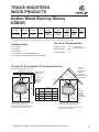
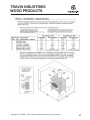
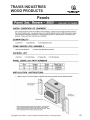
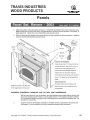
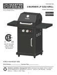
Avalon Wood Burning Stoves
SPOKANE
Model 1250
Model 1750
Height - Legs 26 1/2
Height - Pedestal 29 3/4
Width - 23 5/8
Depth - 14 5/8
Flue Center From Back - 4 1/8
Height - Legs 26 1/2
Height - Pedestal 30 5/8
Width - 24
Depth - 23 1/2
Flue Center From Back - 5 3/4
EPA
Emissions
4.4 Grams/Hr.
Efficiency
Up To 79.6 %
Maximum
Heating Capacity*
Burn Time**
600 to
Up to 8 Hours
1,200 Sq. Ft.
Maximum
Btu s/Hour**
66,800
Firebox
Size
1.6 Cu. Ft.
Maximum
Log Length
Up to 18 inches
Weight
243 Lbs.
EPA
Emissions
1.9 Grams/Hr.
Efficiency
Up To 79.6 %
Maximum
Btu s/Hour**
72,400
Firebox
Size
2.2 Cu. Ft.
Maximum
Heating Capacity* Maximum
Log Length
Burn Time**
1.200 to
2,000 Sq. Ft. Up to 10 Hours Up to 18 inches
Weight
430 Lbs.
* Heating Capacity may vary depending on the degree of home insulation, floor plan, ambient temperature zone of the area in which you live.
* * BTU Output and Burn Times may vary depending on moisture content of wood, wood type, chimney draft and oxygen supply.
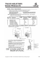
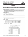
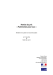
Clearances To Combustibles
Side Wall
Back Wall
A
6
Min.
B
6
16
Floor
Protection
Min.
Model
1250
Single Wall
Connector
Double Wall
Connector
A=
B=
C=
D=
19 1/4
10
11 1/4
26 1/2
17 1/4
10
Single Wall
Connector
Double Wall
Connector
Model
1750
A=
B=
C=
D=
27
17 3/4
15
15
24
15
4 1/4
13
15
6 1/2
Measure rear and side clearances (A)
(B) & (C) from edge of the stove
flue. Measure corner clearance (D)
from the top corner of stove.
6
C
Min.
D
6
16
Min. Floor
Min.
Note: Vent diameter
may vary
depending
on brand and
model.
Protection
Measure front, rear and side Hearth Pad clearances from edges of the stove top. Floor protection must be non-combustible and at least .018 thick
(26 gauge). Minimum Hearth Pad Sizes: Model 1250 - 36 Wide x 37 Depth
Model 1750 - 36 Wide x 45 1/2 Depth
For all installation and clearance information please consult the Owner s Manual or visit www.avalonfirestyles.com.
Copyright © 3/17/2008 - Travis Industries Certified Factory Training Program
3
TRAVIS INDUSTRIES
WOOD PRODUCTS
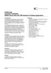
Avalon Wood Burning Stoves
28 5/8”*
29 3/4”*
30”*
32 1/8”*
33 1/4”*
33 3/8”*
16 1/8”
285 lbs.
260 lbs.
345 lbs.
305 lbs.
465 lbs.
* Includes flue collar
Copyright © 3/17/2008 - Travis Industries Certified Factory Training Program
4
TRAVIS INDUSTRIES
WOOD PRODUCTS
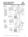
Avalon Wood Burning Stoves
ARBOR
EPA
Emissions
Overall
Efficiency
Maximum
Btu s/Hour**
Firebox
Size
Heating
Capacity*
Maximum
Burn Time**
Maximum
Log Length
Wood
Capacity
Weight
2.4 Grams/Hr.
70 %
73,100
2.3 Cu. Ft.
Up to
2,000 Sq. Ft.
Up to
12 to 18 Hours
Up to
21 inches
45-65
Pounds
375 Lbs.
* Heating Capacity may vary depending on the degree of home insulation, floor plan, ambient temperature zone of the area in which you live.
¥¥ BTU Output and Burn Times may vary depending on moisture content of wood, wood type, chimney draft and oxygen supply.
Alcove Clearances
Dimensions
27 1/4 WIDE
Maximum Depth
48
22 7/8 DEEP
Maximum Width
63 1/4
27 3/4 HEIGHT
Minimum Height
84
Measured From
Combustible Surfaces
25 1/4 HEIGHT TO FLUE CENTER (REAR VENT)
2 5/8 DEPTH TO FLUE CENTER FROM BACK (TOP VENT)
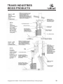
Close Clearances To Combustibles
Typical flue
center
Single Wall 26
(Rear heat shield is a standard feature)
Minimum Flue Center 31-3/4
Side Wall
Back Wall
A
6 Min.
B
6 Min.
16 Min.
Floor Protection
Typical flue center
Single Wall 24
Reduced
Clearance 21
Reduced
Clearance 17.5
Single Wall
with Pipe
Shield 14
Single Wall
Connector
21
A=
B = 28 3/4
23
C=
19
D=
Single Wall with
Pipe Shield 21
6 Min.
C
D
Single Wall
Connector
w/Pipe Shield
11
28 3/4
18
14
6 Min.
Double Wall
Connector
14
28 1/4
17 1/2
14
16 Min.
Floor Protection
Note: Vent
diameter
may vary
depending
on brand and
model.
Measure front clearances from the face
of the stove (door opening).
Measure rear and side clearances from
the nearest edge of the stove top.
Measure rear and side clearances from
the nearest edge of the stove top.
Measure front clearances from the face of
the stove (door opening).
Copyright © 3/17/2008 - Travis Industries Certified Factory Training Program
5
TRAVIS INDUSTRIES
WOOD PRODUCTS
Avalon Wood Burning Inserts
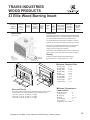
RAINIER
PERFECT-FIT
OLYMPIC
For smaller homes and for zonal heating needs.
45˚ Flue or 90˚ Flue Models
For mid-sized homes and for zonal heating needs.
45˚ Flue or 90˚ Flue Models
Flush wood insert for mid-sized
homes and for zonal heating.
For larger homes and those who
need a primary heat source.
Heating Capacity*:
Heat Output:
Overall Efficiency*:
Max, Burn Time:
Max. Log Size:
Fuel Capacity:
Weight:
Firebox Size:
Flue Diameter:
600 to 1,200 SQ. FT.
64,200 BTU’s/HR
68%
Up to 8 Hours
Up to 17”
16 Lbs. of Wood
285 Lbs.
1.3 Cu. In.
6”
45˚ Flue
90˚ Flue
800 to 1,800 SQ. FT.
71,800 BTU’s/HR
71.7%
Up to 9 Hours
Up to 20”
22 Lbs. of Wood
345 Lbs.
1.8 Cu. In.
6”
45˚ Flue
90˚ Flue
1,200 to 2,000 SQ. FT.
73,300 BTU’s/HR
71.7%
Up to 12 Hours
Up to 24”
22 Lbs. of Wood
450 Lbs.
2.9 Cu. In.
6”
90˚ Flue
1,500 to 2,500 SQ. FT.
74,300 BTU’s/HR
70%
Up to 12 Hours
Up to 24”
24 Lbs. of Wood
465 Lbs.
3.1 Cu. In.
6”
90˚ Flue
Height:
Width in Front:
Width in Back:
Overall Depth:
Depth on Hearth:
Depth Into Fireplace:
20 ”
23 3/4”
23 3/4”
16 1/8”
4 3/4”
11 3/8”
20 3/4”
23 3/4”
23 3/4”
16 3/8”
4 7/8”
21 1/8”
25 3/4”
25 3/4”
19 3/8”
10”
21 7/8”
25 3/4”
25 3/4”
19 3/8”
5 1/8”
11 5/8”Masonry 12 5/8” ZC
9 1/2”Masonry 10 1/2” ZC
14 1/2”Masonry 15 1/2” ZC
21 1/2”
28 7/8”
21 1/4”
21 3/4”
1 1/4”
20 1/2”
22 1/8”
29 3/8”
29 3/8”
20 1/2”
6 3/8” FL 8 7/8” EXT
14 1/8” FL 11 5/8” EXT
PENDLETON
* Wood appliance performance can be affected by negative pressure in the home and by prevailing atmospheric conditions. Contact local building or fire officials about restrictions and installation requirements in your area.
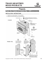
SURROUND FACING Select the panels to enclose your fireplace opening. Measurements indicate maximum coverage area.
OUTSIDE FIT PANELS - Designed to fit over the existing fireplace opening. Comes standard with black trim.
8” x 8” Panels:
10” x 10” Panels:
12” x 12” Panels:
39 3/4” W x 28” H
43 3/4” W x 30” H
47 3/4” W x 32” H
41 3/4” W x 28 7/8” H
45 3/4” W x 30 7/8” H
49 3/4” W x 32 7/8” H
45 1/2” W x 29 1/2” H
49 1/2” W x 31 1/2” H
53 1/2” W x 33 1/2” H
45 1/4” W x 28 7/8” H
49 1/4” W x 30 7/8” H
53 1/4” W x 32 7/8” H
INSIDE FIT PANELS - All Avalon panels sets can be cut down for a custom fit to the inside edges of your existing fireplace opening. It is the least obtrusive panel system and showcases your Avalon insert.
CLEARANCES TO COMBUSTIBLES Complete installation information is avaialbe
A = To Mantle
A = To Mantle
B = w/Shield*
B = To Top Facing
B = To Top Facing
D = w/Shield*
C = To Sidewall
D = To Side Facing
E = Hearth Depth
F = Hearth Sides
at your local Avalon dealer or on our website at www.avalonstyle.com.
Masonry
Fireplace
Metal (ZC)
Fireplace
Masonry
Fireplace
Metal (ZC)
Fireplace
Masonry
Fireplace
Metal (ZC)
Fireplace
Masonry
Fireplace
Metal (ZC)
Fireplace
Metal (ZC) Fireplace
22”
16 1/2”
24”
N/A
22”
16 1/2”
24”
N/A
31 1/2”
16 1/2”
24”
N/A
31 1/2”
16 1/2”
24”
N/A
41 1/2” (Measured From Floor)
20”
14 1/2”
12”
N/A
20”
14 1/2”
12”
N/A
29 1/2”
14 1/2”
12”
N/A
29 1/2”
14 1/2”
12”
N/A
10”
9”
20 3/4“
8”
30”
12”
20 3/4“
8”
14”
13”
26 “
8”
30”
12”
26 “
8”
30”
14”
12”
13”
21 1/8 “ 21 1/8 “
8”
8”
30”
10”
12”
9”
20 3/4“ 20 3/4“
8”
8”
Metal (ZC) Fireplace
Flush
Extended
N/A
32”
19”
33”
20”
39” (Measured From Floor)
N/A
30”
17”
31”
18”
9”
9”
17 1/4 “
8”
15”
13 1/2”
22 3/8 “
8”
15”
13 1/2”
24 7/8 “
8”
* Mantle and Top Facing clearances can be reduced with the optional Mantle Shield
SIZING YOUR EXISTING FIREPLACE
Minimum
Requirements:
G = Height
H = Front Width
I = Back Width
J = Depth
K = Min. Lintel Depth
A
45˚ Flue
90˚ Flue
45˚ Flue
90˚ Flue
90˚ Flue
Flush
Extended
20 1/2”
24”
24”
11 3/8”
6 1/2”
21 1/4”
24”
24”
21 1/2”
26”
26”
22 1/4”
26”
26”
21 1/2”
30 7/8”
21 1/4”
20 1/2
11”
22 1/4”
29 1/2”
29 1/2
14 1/8”
5”
22 1/4”
29 1/2”
29 1/2”
11 5/8”
2 1/2”
11 5/8”Masonry 12 5/8” ZC
4 1/2”
B
D
J
G
I
F
9 1/2”Masonry 10 1/2” ZC 14 1/2”Masonry 15 1/2” ZC
3 1/4”
K
C
E
Minimum fireplace measurements required for installation
H
7”
Write In Your Fireplace Dimensions:
G = Height
_________
H = Front Width
_________
I = Back Width
_________
APPROVED ZERO CLEARANCE (METAL) FIREPLACES
Both the Pendleton and Rainier Inserts are approved for installation
in the following zero clearance fireplaces. See the Owner’s Manual
for details.
MARCO
MAJESTIC
TEMPCO
Copyright © 3/17/2008 - Travis Industries Certified Factory Training Program
HEATILATOR PREWAY
SUPERIOR
6
TRAVIS INDUSTRIES
WOOD PRODUCTS
Lopi Wood Burning Stoves
Republic
Republic
1250
1750
Small
Medium
ANSWER
ENDEAVOR
LIBERTY
Small
Medium
Large
SPECIFICATIONS
Width
Height (All Legs)
Height (Pedestal)
Depth
Flue Size
Construction
(plate steel)
Weight (body w/legs)
23 5/8"
26 3/4"
29 3/4"
14 5/8"
6"
24"
26 1/2"
30 5/8"
23 1/2"
6"
23 5/8"
27 7/8"
31 7/8"
16 1/4"
6"
24"
30 5/8"
34 5/8"
23 1/2"
6"
30"
32 1/4"
36 1/4"
21"
6"
1/4" to 3/16"
243 lbs.
5/16" to 3/16"
430 lbs.
1/4" to 3/16"
300 lbs.
5/16" to 3/16"
448 lbs.
5/16" to 3/16"
490 lbs.
4.4 Grams/Hr.
750 to 1,400
66,800 BTU's/Hr.
Up To 79.6%
Up To 8 Hours
1.6 Cubic Ft.
Up To 18"
1.9 Grams/Hr.
1,200 to 2,000
72,400 BTU's/Hr.
Up To 78.8%
Up To 10 Hours
2.2 Cubic Ft.
Up To 18"
2.6 Grams/Hr.
1,500 to 2,500
74,300 BTU's/Hr.
Up To 76.9%
Up To 12 Hours
3.1 Cubic Ft.
Up To 24"
Single Wall
Connector
Single Wall
Connector
Double Wall
Connector
PERFORMANCE
Emissions
Heating Cap. (Sq Ft.)
Heat Output
Efficiency (DEQ)
Maximum Burn Time
Firebox Size
Maximum Log Size
4.4 Grams/Hr.
600 to 1,200
66,800 BTU's/Hr.
Up To 79.6%
Up To 8 Hours
1.6 Cubic Ft.
Up To 18"
CLEARANCES
Single Wall
Connector
A= Stove to Side wall
B= Stove to Back wall
C= Stove to Corner Wall
D= Connector to
Side Wall
E= Connector to
Back wall
F= Connector to
Corner Wall
18"
18"
10"
1.9 Grams/Hr.
1,200 to 2,000
72,400 BTU's/Hr.
Up TO 78.8%
Up To 10 Hours
2.2 Cubic Ft.
Up To 18"
Double Wall
Connector
Double Wall
Connector
Single Wall
Connector
Double Wall
Connector
Single Wall
Connector
18"
10 1/2"
10"
15"
15"
15"
13"
4 1/4"
6 1/2"
18"
16 1/2"
10"
13"
9"
7 1/2"
15"
15"
15"
13"
4 1/4"
6 1/2"
16"
15"
9 1/2"
16"
10"
7 1/2"
27"
26 1/2"
24"
21 1/2"
27"
21 1/2"
24"
21 1/2"
28"
27 1/2"
19 1/4"
11 1/4"
17 3/4"
6 1/2"
19 1/2"
11 1/2"
17 3/4"
6 1/2"
18 1/4"
12 3/4"
17 3/4"
17 1/4"
24"
15"
19 1/2"
16 1/2"
24"
15"
21"
18 1/2"
Double Wall
Connector
Hearth Protection
G= Front
H= Sides
I= Back
16"
6"
6"
16"
6"
6"
16"
6"
6"
16"
6"
6"
16"
6"
6"
59 5/8"
48"
84"
54"
48"
84"
49 5/8"
48"
84"
54"
48"
84"
62"
48"
84"
ALCOVE
J= Maximum Width
K= Minimum Depth
L= Minimum Height
Clearances to Unprotected
Combustibles
INSTALLATIONS
STRAIGHT WALL
CORNER WALL
ALCOVE
Use these illustrations in conjunction with
the information under the "Clearance" &
"Alcove" headings above.
*Heating Capacity may vary depending on degree of home insulation, floor plan and ambient temperature zone of the area in which you live.
Copyright © 3/17/2008 - Travis Industries Certified Factory Training Program
7
TRAVIS INDUSTRIES
WOOD PRODUCTS
Lopi Wood Burning Stoves
LEYDEN
EPA
Emissions
Overall
Efficiency
Maximum
Btu s/Hour**
Firebox
Size
Heating
Capacity*
Maximum
Burn Time**
Maximum
Log Length
Wood
Capacity
Weight
2.4 Grams/Hr.
70 %
73,100
2.3 Cu. Ft.
Up to
2,000 Sq. Ft.
Up to
12 to 18 Hours
Up to
21 inches
45-65
Pounds
375 Lbs.
* Heating Capacity may vary depending on the degree of home insulation, floor plan, ambient temperature zone of the area in which you live.
¥¥ BTU Output and Burn Times may vary depending on moisture content of wood, wood type, chimney draft and oxygen supply.
Alcove Clearances
Dimensions
A = Maximum Depth
27 1/4”
22 7/8”
17”
48
B = Maximum Width 63 1/4
2 5/8”
C = Minimum Height
Measured From
Combustible Surfaces
84
5 3/4”
27 3/4”
C
25 1/4”
B
Measure side, corner, and back
clearances from the stove top.
A
Close Clearances To Combustibles
Typical flue
center
Single Wall 26
(Rear heat shield is a standard feature)
Minimum Flue Center 31-3/4
Side Wall
Back Wall
A
6 Min.
B
6 Min.
16 Min.
Floor Protection
Typical flue center
Single Wall 24
Reduced
Clearance 21
Reduced
Clearance 17.5
Single Wall
with Pipe
Shield 14
Single Wall
Connector
21
A=
B = 28 3/4
23
C=
19
D=
Single Wall with
Pipe Shield 21
6 Min.
C
D
Single Wall
Connector
w/Pipe Shield
11
28 3/4
18
14
6 Min.
Double Wall
Connector
14
28 1/4
17 1/2
14
16 Min.
Floor Protection
Note: Vent
diameter
may vary
depending
on brand and
model.
Measure front clearances from the face
of the stove (door opening).
Measure rear and side clearances from
the nearest edge of the stove top.
Measure rear and side clearances from
the nearest edge of the stove top.
Measure front clearances from the face of
the stove (door opening).
Copyright © 3/17/2008 - Travis Industries Certified Factory Training Program
8
TRAVIS INDUSTRIES
WOOD PRODUCTS
Lopi Wood Burning Inserts
ANSWER
REVERE
Zero Clrarance Approved
Zero Clrarance Approved
FREEDOM
DECLARATION
Large
Medium
Small
FREEDOM BAY
SPECIFICATIONS
Width
Height
Depth (overall)
Depth on Hearth
Depth into Fireplace
Flue Size
Construction (plate steel)
Weight (body)
23 5/8"
20 3/4"
16 1/4"
3"
13 1/2"
6"
5/16" to 3/16"
300 lbs.
24 1/4"
19 3/4"
23 1/8"
10"
13 1/8"
6"
5/16" to 3/16"
380 lbs.
28 7/8"
21 1/2"
21 3/4"
1 1/4"
20 1/2"
6"
5/16" to 1/4"
450 lbs.
Emissions
Heating Capacity
4.4 Grams/Hr.
750 to 1,200 Sq. Ft.
1.9 Grams/Hr.
1,200 to 2,000
Heat Output (Cord Wood)
Efficiency (DEQ)
Maximum Burn Time
Firebox Size
Maximum Log Size
66,800 BTU's/Hr.
Up To 79.6%
Up To 8 Hours
1.6 Cubic Ft.
18"
72,400 BTU's/Hr.
Up To 78.8%
Up To 10 Hours
2.2 Cubic Ft.
18"
73,300 BTU's/Hr.
Up To 76.9%
Up To 12 Hours
2.9 Cubic Ft.
24"
Masonry
Fireplace
Masonry
Fireplace
Masonry
Fireplace
29 1/4"
21 3/4"
20 1/2"
7" (Ext) - 1 5/8" (Flush)
13 1/2"(Ext)-18 7/8"(Flush)
6"
5/16" to 3/16"
455 lbs.
43 3/4"
21 3/4"
20 1/2"
4 3/4"
15 3/4"
6"
5/16" to 3/16"
470 lbs.
3.2 Grams/Hr.
1,200 to 2,250 Sq. Ft. (ext.)
1,200 to 2,000 Sq. Ft. (fl.)
73,300 BTU's/Hr.
Up To 76.9%
Up To 12 Hours
2.9 Cubic Ft.
24"
2.6 Grams/Hr.
1,200 to 2,250
Masonry
Fireplace
Extended
Masonry
Fireplace
PERFORMANCE
CLEARANCES
Metal (ZC)
Fireplace
Sq. Ft.
Metal (ZC)
Fireplace
4.1 Grams/Hr.
1,200 to 2,000
Sq. Ft.
Masonry
Fireplace
w/flush kit
74,300 BTU's/Hr.
Up To 76.9%
Up To 12 Hours
3.1 Cubic Ft.
24"
A= Firebox to Mantel
A= With Mantel Shield
15 1/2"
N/A
24"
N/A
30 1/2"
22 1/2"
24"
N/A
41 1/2" (measured from floor) 32"
19"
N/A
20"
N/A
32"
19"
B= Firebox to Top Facing
B= With Mantel Shield
12"
N/A
12"
N/A
28 1/2"
20 1/2"
12"
N/A
39" (measured from floor)
N/A
30"
17"
20"
N/A
30"
17"
C= Firebox Side to
B= Side Facing
9 1/2"
12"
13"
12"
9"
13 1/2"
13 1/2"
13 1/2"
D= Firebox Side to
B= Side Wall
13"
30"
15"
30"
9"
15"
15"
15"
FIREPLACE SIZING
E= Minimum Depth
F= Minimum Front Width
G= Minimum Back Width
H= Minimum Height
Masonry
Fireplace
Metal (ZC)
Fireplace
Masonry
Fireplace
13 1/2"
23 5/8"
23 5/8"
20 3/4"
14 1/2"
25 5/8"
25 5/8"
20 3/4"
13
24
21
19
1/8"
1/4"
5/8"
3/4"
Metal (ZC)
Fireplace
14
26
23
19
1/8"
1/4"
5/8"
3/4"
Masonry
Fireplace
Masonry
Fireplace
Extended
Masonry
Fireplace
w/flush kit
Masonry
Fireplace
20 1/2"
30 7/8"
21 1/4"
21 1/2"
13
29
21
21
18
29
21
21
15
29
29
21
PANEL SIZES
7/8"
1/4"
1/4"
3/4"
3/4"
1/4"
1/4"
3/4"
Ask Your Dealer For Sizing
On Arched Panels. (Freedom
Only)
Rectangular Panels Listed.
8" x 8"
10" x 10"
12" x 12"
1/2"
1/4"
1/4"
3/4"
Sq. Ft.
28 1/4" H x 40 1/8" W
30 1/4" H x 44 1/8" W
N/A
27 5/8" H x 40 3/8" W
29 5/8" H x 44 3/8" W
31 5/8" H x 48 3/8" W
29 1/2" H x 45 1/2" W
31 1/2" H x 49 1/2" W
33 1/2" H X 53 1/2" W
29 1/2" H x 45 3/8" W
31 1/2" H x 49 3/8" W
33 1/2" H x 53 3/8" W
Clearances to Unprotected Combustibles:
Sizing Your Fireplace for an Insert:
Use these illustrations in conjunction with the
information under the "Clearance" & "Alcove"
headings above.
Use these illustrations in conjunction with the informtion under
the "Fireplace Sizing" headings above.
All Inserts except the
Declaration must have a noncombustible hearth pad that
extends a minimum of 16" in
front of the insert and 6"
to the sides.
Please use the provided chart on the right
to mark down your fireplace dimensions.
This will assist you in determining the
right Lopi insert for your fireplace.
29 1/2" H x 45 3/8" W
31 1/2" H x 49 3/8" W
33 1/2" H x 53 3/8" W
Approved ZC Fireplaces:
The Declaration must have a
noncombustible hearth pad that extends a minimum of
17 1/4" in front of the Lopi insert and 8" to the sides.
The Answer and Endeavor inserts are
approved for Marco, Majestic, Heatilator, Superior, Preway and Tempco
zero clearance fireplaces. See the Owner's Manual for details.
Copyright © 3/17/2008 - Travis Industries Certified Factory Training Program
Your Fireplace
measurements
E.
Depth
F.
Front Width
G.
Back Width
H.
Height
9
TRAVIS INDUSTRIES
WOOD PRODUCTS
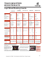
33 Elite Wood Burning Insert
EPA Phase II
Approved
4.1
Grams/Hour
Maximum
Btu’s
Per Hour
73,300
Overall
Efficiency
71.1%
Heating
Up To
Capacity
12 Hour
Burn
1,200 to
2,000 Sq. Ft. Time
2.9
Cubic
Foot
Firebox
Accepts
24”
Wood
Heavy Gauge
Plate Steel
Construction
5/16” & 1/4”
Heavy-Duty
Masonry
Lined Firebox
& Baffle
180 CFM
Convection
Blower
Standard
Installation
Dimensions
We suggest that you have an authorized Fireplace Xtrordinair dealer
install your fireplace insert. If you install the fireplace insert yourself,
your authorized dealer should review your installation plans.
The 33 Elite Wood Insert is designed for installation in masonry
fireplaces. Do not install into a factory-built metal (Z.C.) fireplace.
Check with your local building officials for any permits required for
installation of this fireplace insert and notify your insurance
company before proceeding with installation.
The 33 Elite must be installed with either Positive Flue (full chimney
reline) or Direct Connect Flue (See Owner’s Manual for details).
Testing
Tested and certified by OMNI-Testing Laboritories Inc.
Report # 028-S-54-2 Safety Tested to U. L. 1482
Minimum Fireplace Size
J
H
A
L
B
K
N
D
E
C
M
I
F
G
P
21 1/2”
21 1/2”
30 7/8”
21 1/4”
20 1/2”
17 1/4”
44 7/8”
46 7/8”
39”
41 1/2”
O
Surround Panels
The surround panels are designed to finish off the fireplace opening. Surround panels
can also be custom cut to fit the inside dimensions of your fireplace opening.
8” Panel Set - Covers 45 1/2” Wide x 29 1/2” Height
10” Panel Set - Covers 49 1/2” Wide x 31 1/2” Height
12” Panel Set - Covers 53 1/2” Wide x 33 1/2” Height
A - Height (Front)
B - Height (Rear)
C - Width (Front)
D - Width (Rear)
E - Depth
F - Hearth Depth
G - Hearth Width
H - Facing Width
I - Facing Height
J - Mantel Height
Minimum Clearances to
Combustibles
K - Sidewall To Insert
L - Side To Facing
M - Top Facing
N - Mantle
O - Hearth (Side)
P - To Any Room
Combustible (i.e. chair, curtains)
Copyright © 3/17/2008 - Travis Industries Certified Factory Training Program
9”
9”
39”
41 1/2”
8”
36”
10
TRAVIS INDUSTRIES
WOOD PRODUCTS
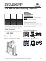
36 & 44 Elite Wood Burning Fireplaces
Features &
Specifications
EPA Phase II Approved
Overall Efficiency*
Heating Capacity
Emissions**
Maximum Burn Time^
Flue
Overall Width
Overall Depth
Firebox Capacity
Wood Size
BTU Output Cordwood
Model 36 Elite
Zero Clearance
YES
73%
Up to 2,500 Sq./Ft.
2.3 Grams/Hour
10 Hours
8" Opening I.D.
42"
27"
3.7 Cubic Feet
24"
10,300 to 66,000 Per/Hr.
*DEQ Method **EPA Method
Model 44 Elite
Zero Clearance
YES
72%
Up to 3,000 Sq./Ft.
2.5 Grams/Hour
12 Hours
8" Opening I.D.
48"
27"
4.3 Cubic Feet
32"
10,700 to 76,700 Per/Hr.
Not Including Faceplate
^ Emissions, Efficiency, Heating Capacity and Burn Time may very
depending on actual home floor plan, type of fuel used, and moisture
content. Emissions numbers are those that have been certified by the U.S.
E.P.A. BTU output based on burning cordwood. Efficiency numbers are
based on Oregon Dept. of Environmental quality test standards.
Framing Specifications
Clearance
Specifications
To Combustible Mantle:
23" from fireplace face.
To Combustible Facing:
Top Facing 12 - Side Facing 2 1/2 from fireplace face.
Hearth:
Requires a 20" non-combustible hearth.
Approved Air-Cooled Chimney:
FMI 8HT & Firecraft FTF8 A
Improper installation of your wood burning fireplace or failure to
operate it according to the guidelines detailed in the Owner s
Manual, may negate your warranty and endanger your home and
family. Contact your local building or fire officials about restrictions
and installation requirements in your area.
Model 36 Elite Zero Dimensions
Please consult your Owner s Manual for Framing Specs.
1 1/2"
Flange
A=
B=
C=
36 Elite 44 Elite
45 1/2
50 1/2
26
26
43
50
4 1/2"
4"
42"
4 1/2"
41"
11
26"
7"
20 1/2"
6 1/2"
FACE
3"
42"
NOTE: Make sure the enclosure is wide enough to
accommodate the blower (see Owner s Manual for
details).
Model 44 Elite Zero Dimensions
1 1/2"
Flange
3 7/8"
5"
49"
4 1/2"
8 1/8"
46"
6 1/2"
49"
11 5/8"
26 1/8"
24 1/2"
3 1/4"
FACE
Blower
Copyright © 3/17/2008 - Travis Industries Certified Factory Training Program
11
TRAVIS INDUSTRIES
WOOD PRODUCTS
• Unibody construction
• Single Air Control
• Minimum clearances to combustibles
• Operation/Care manual and touch-up paint
• Easy start-up and refueling with bypass damper
(most models)
• Non-Catalytic EPA Phase II clean burning
• 6” flue on all models
• 3/16” - 1/4” - 5/16” steel construction
• Long burn times
• Easy operation cam lever door lock
Copyright © 3/17/2008 - Travis Industries Certified Factory Training Program
12
TRAVIS INDUSTRIES
WOOD PRODUCTS
• One out of every five woodstoves sold in North
America is a Travis product
• “Real World” seven year warranty
• Clean burn airwash
• Replaceable air tubes, firebrick baffle
• and baffle retainers
• Radiant and convection heaters (3 and 5 sides to
convection chamber)
• Heats up to 2,500 Sq. Ft.
• Clearview ceramic glass
• Clay, kiln fired firebrick
Copyright © 3/17/2008 - Travis Industries Certified Factory Training Program
13
TRAVIS INDUSTRIES
WOOD PRODUCTS
Wood As Fuel
• Wood is renewable natural resource.
OX
AT
YG
HE
EN
• Wood is a hydrocarbon, or in other words - it is made up
• of hydrogen and carbon atoms.
FIRE
FUEL (WOOD)
• Combustion of wood takes place when we mix the right
• quantities of fuel (wood), heat & oxygen.
• When proper balance exist between these items complete
• combustion takes place and produces:
- Water Vapor
- Carbon Dioxide
- Heat
- Non-Combustible Ash
Copyright © 3/17/2008 - Travis Industries Certified Factory Training Program
14
TRAVIS INDUSTRIES
WOOD PRODUCTS
Wood As Fuel
STAGES OF WOOD COMBUSTION
STAGE 1 - Moisture Evaporation
• The wood is heated and the contained moisture evaporates
• to form steam.
• NO HEAT is given off - it is all absorbed in drying out
the wood.
STAGE 2 - Vaporization of Hydrocarbon Compounds
• The chemical structure of wood molecules begin to
• breakdown and hydrocarbons begin to vaporize. This • •
• process is known as pyrolysis.
• During pyrolysis liquid tar droplets and combustible gas
• are produced from the hydrocarbons.
• This stage is still absorbing heat rather than giving
• off heat.
Copyright © 3/17/2008 - Travis Industries Certified Factory Training Program
15
TRAVIS INDUSTRIES
WOOD PRODUCTS
Wood As Fuel
STAGES OF WOOD COMBUSTION
STAGE 3 - Gas Vapor Ignition & Combustion
• Gases and tar droplets produced in stage two, ignite in •
• stage 3. They ignite between the temperatures of 540˚F
• to1225˚F.
• Temperatures in the firebox may reach upwards of 2000˚F
• during this stage of burning.
STAGE 4 - Char Burning
• After pyrolysis, moisture evaporation, and the release of
• gases have subsided (about 950˚F), the char burning
• stage begins.
• The carbon in charcoal is the only remaining combustible
• material. Charcoal burns with little or no flame and • •
• produces temperatures of about 1100˚F.
Copyright © 3/17/2008 - Travis Industries Certified Factory Training Program
16
TRAVIS INDUSTRIES
WOOD PRODUCTS
Emissions
• Over the years, air quality has become an issue and
wood burning products were sited as contributing to
poor air quality.
• In 1990, EPA (Environmental Protection Agency) became
the agency to regulate the emissions of wood products.
• Today’s EPA particulate emission standards are:
- Catalytic products
- 4.1 Grams/Hour
- Non-Catalytic products:
- 7.5 Grams/Hour
• Most states follow the EPA standard however states may
have more stringent requirements.
• Washington State is one of those States:
- Catalytic products
- 2.5 Grams/Hour
- Non-Catalytic products:
- 4.5 Grams/Hour
Copyright © 3/17/2008 - Travis Industries Certified Factory Training Program
17
TRAVIS INDUSTRIES
WOOD PRODUCTS
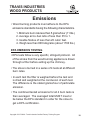
Emissions
• Wood burning products must adhere to the EPA
• emissions standards having the following characteristics.
1. Minimum burn rate less than 5 grams/hour (11 lbs.)
2. Average air-to-fuel ratio of less then 35 to 1.
3. Usable firebox of less than 20 cubic feet.
4. Weigh less than 800 kilograms (about 1760 lbs.)
EPA EMISSION TESTING
• EPA tests follow a very specific, stringent protocol. All
• of the smoke from the wood burning appliance is drawn
• through a filter before exiting up the chimney.
• The stove is burned in a series of 4 tests all at different
• burn rates.
• In each test the filter is weighed before the test and •
• is dried and weighted at the conclusion of each test.•
• The difference is the stated grams/hour of particulate
• emission.
• The combined tested emissions for all 4 burn tests is
• then averaged. The averaged total MUST meet or •
• be below the EPA standard in order for the stove to
• get a EPA certification.
Copyright © 3/17/2008 - Travis Industries Certified Factory Training Program
18
TRAVIS INDUSTRIES
WOOD PRODUCTS
EPA Hang Tag
• EPA hang tags must be present ON each woodburning
• in your showroom.
• Non-compliance may result in a $5,000 fine per unit.
Copyright © 3/17/2008 - Travis Industries Certified Factory Training Program
19
TRAVIS INDUSTRIES
WOOD PRODUCTS
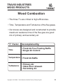
Wood Combustion
• The three T’s are critical to high efficiencies.
• Time, Temperature and Turbulence of the flue gases.
• Our stoves are designed and constructed to provide
• maximum residence time of the flue gas at a good •
• mix of primary and secondary air.
“T” Factor
Accomplished By:
Time
• Firebrick Free Floating Baffle
• Single Air Control
Temperature • Firebrick Baffle
Turbulence
• Primary Air
• Glass Door Airwash
• Secondary Air
Copyright © 3/17/2008 - Travis Industries Certified Factory Training Program
20
TRAVIS INDUSTRIES
WOOD PRODUCTS
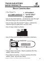
Stove Construction
• The Three T’s
1. EFFICIENCY
ACCOMPLISHED BY 2. “GOOD HEAT”
3. TRANSFER
• Use of clay fired firebrick - conducts the heat through
• the brick lining to the convection chambers.
• Use of clear view Neoceram™ glass - reflects the • •
• heat through the glass door into the room.
• Use of large radiant surfaces.
• Use of three and five-sided convection chambers.
Heated Air
HOT!
CONVECTION
Cool Air
• Three-sided convection- Heat is washed off of the
• bottom, back and top.
• Five-sided convection - Heat is washed off of the
• bottom, back, top and two sides.
Copyright © 3/17/2008 - Travis Industries Certified Factory Training Program
•
21
TRAVIS INDUSTRIES
WOOD PRODUCTS
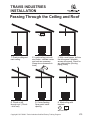
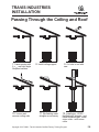
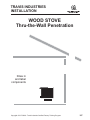
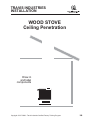
Wood Stove Venting
• The pipe which connects the stove to the chimney
is called a connector.
• The stove connector must connect to a masonry
chimney or a metal factory built type UL103 HT
chimney.
• Connectors must never pass through a wall or ceiling.
• Stove connectors may be single wall pipe or double •
wall pipe with an air space between the inner and •
outer wall.
• The system shall not have more than 180˚ of turn
• (2-90˚ elbows or 1-90˚ elbow and 2-45˚ elbows).
• Chimney must be masonry constructed in accordance
• with NFPA 211 standards or factory built chimney • •
tested to the UL103 HT standard.
Copyright © 3/17/2008 - Travis Industries Certified Factory Training Program
22
TRAVIS INDUSTRIES
WOOD PRODUCTS
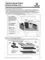
Single Wall Connector
Single Wall
Pipe
Single Wall Slip
Connector
Single Wall
Elbow
• Single Wall Connector
Construction
• 24 MSG Black or 26 MSG Blued Steel
Lengths
• 12”-24”- 48”
• Slip connector which allows for 10”
• adjustment
Advantages
• Radiates heat into room
• Inexpensive
Disadvantages • Requires 18” clearance to combustibles
• Removes too much heat potentially
• creating creosote build-up and harder
start-up
Copyright © 3/17/2008 - Travis Industries Certified Factory Training Program
23
TRAVIS INDUSTRIES
WOOD PRODUCTS
Double Wall Connector
Double Wall
Pipe
Double Wall
Telescoping
Double Wall
Elbow
• Double Wall Connector
Construction
• Stainless steel inner liner - Galvanized
outer shell
Lengths
• 6”-12”-18”-24”- 48”
• Telescoping 29”to48’ & 40’ to 68”
Advantages
• Close clearance reduction
NOTE: Only listed, tested close clearance
• connectors may be used on Travis wood
• products. Must be used for close clearance,
alcove and mobile home installations.
• Keeps chimney cleaner as flue stays hotter.
• Makes for easier start-up of the fire
Disadvantages • More expensive
Copyright © 3/17/2008 - Travis Industries Certified Factory Training Program
24
TRAVIS INDUSTRIES
WOOD PRODUCTS
Factory Built Chimney
• Factory Built Chimney
Construction
• Stainless steel inner and stainless steel
or galvanized outer with blanket
insulation in between inner and outer and
or air space
Lengths
• 6”-12”-18”-24”-36”-48”
Listings
• UL103 HT listing 2100˚
Copyright © 3/17/2008 - Travis Industries Certified Factory Training Program
25
TRAVIS INDUSTRIES
WOOD PRODUCTS
Copyright © 3/17/2008 - Travis Industries Certified Factory Training Program
26
TRAVIS INDUSTRIES
WOOD PRODUCTS
Copyright © 3/17/2008 - Travis Industries Certified Factory Training Program
27
TRAVIS INDUSTRIES
WOOD PRODUCTS
Copyright © 3/17/2008 - Travis Industries Certified Factory Training Program
28
TRAVIS INDUSTRIES
WOOD PRODUCTS
Copyright © 3/17/2008 - Travis Industries Certified Factory Training Program
29
TRAVIS INDUSTRIES
WOOD PRODUCTS
Copyright © 3/17/2008 - Travis Industries Certified Factory Training Program
30
TRAVIS INDUSTRIES
WOOD PRODUCTS
Rear Blower
Copyright © 3/17/2008 - Travis Industries Certified Factory Training Program
31
TRAVIS INDUSTRIES
WOOD PRODUCTS
Front Blower
Copyright © 3/17/2008 - Travis Industries Certified Factory Training Program
32
TRAVIS INDUSTRIES
WOOD PRODUCTS
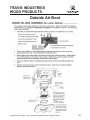
Outside Air Boot
Copyright © 3/17/2008 - Travis Industries Certified Factory Training Program
33
TRAVIS INDUSTRIES
WOOD PRODUCTS
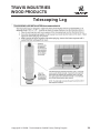
Telescoping Leg
Copyright © 3/17/2008 - Travis Industries Certified Factory Training Program
34
TRAVIS INDUSTRIES
WOOD PRODUCTS
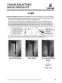
Legs
Cast Solid Brass
Cast Black
Copyright © 3/17/2008 - Travis Industries Certified Factory Training Program
Sculptured Black
Steel
or
Pewter*
*Lopi only
35
TRAVIS INDUSTRIES
WOOD PRODUCTS
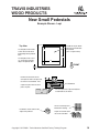
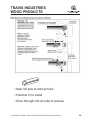
New Small Pedestals
Example Shown - Lopi
Pedestal Attachment
NOTE: If using outside air, install it prior to attaching the pedestal (see Outside Air Installation on page 2 and 3).
Stove
9/16" Wrench
Two pedestal bolts
attach the pedestal to
the bottom of the
stove.
The lag bolts and washers
may be inserted through
these holes to anchor the
pedestal to the floor.
Pedestal
Copyright © 3/17/2008 - Travis Industries Certified Factory Training Program
36
TRAVIS INDUSTRIES
WOOD PRODUCTS
New Small Pedestals
Example Shown - Lopi
Outside Air Installation – Using the Outside Air Kit (99200139)
a
Tuck insulation (included with the
pedestal) under both sides of the
pedestal and under the holes on the
base of the pedestal. This prevents air
from being
drawn from below
the pedestal.
Select a location between
framing members for the
wall penetration.
b Remove the cover
plate on the pedestal.
NOTE: If wall is thicker
than 8", attach the flex duct
to the hood then slide the
hood into place.
Seal the area around
the tube to prevent
air from entering
through the wall.
c
Slide the hood
through the wall and
secure to the outside
wall with the two
Cover Plate
included screws.
Sil
ico
ne
Silico
ne
3" Dia. Flex Duct
(4' max. length)
e
Secure the flex duct to the
air duct assembly using
the included hose clamp.
Attach the outside air duct
assembly to the pedestal
with the same screws that
held the cover plate in
place.
Min. 3"
Dia. Hole
d
Slide the cover plate over the flex duct
then attach the flex duct to the hood with
the included hose clamp. Secure the
cover plate to the wall with the included
screws (and drywall anchors if needed).
8"
HINT: The flex must be fully stretched and
the ends cut square and flatted for it to fit
properly. The tube on the hood and air
duct may be crimped if necessary.
Hood with Rodent Screen
Answer Outside Air Cover Plate
The Answer wood stove can draw combustion air from the inlet near the air control. When using outside air
you will need to install the included cover plate so all of the air is drawn from below. See the directions below.
Remove the two screws on the
cover plate to remove the piece that
fits over the air control rod. Then
replace the piece when the cover
Air Control Rod
plate is in place.
The cover plate has a clip which attaches
it underneath the air control.
Copyright © 3/17/2008 - Travis Industries Certified Factory Training Program
37
TRAVIS INDUSTRIES
WOOD PRODUCTS
New Small Pedestals
Example Shown - Lopi
Outside Air Installation – Through the Pedestal into the Crawl Space
This pedestal has an internal air duct that may be used to direct air to the firebox. Outside air is then drawn from
the crawl space under the stove (check with local building codes for requirements in your area). See the
directions below for installation details.
1
Determine the location of the hole placed under the pedestal. The illustration below details the location of the
pedestal in relation to the front of the stove. The hole should be at least 16 square inches.
Top View
23 1/2"
The faceplate of the Answer
is flush with the front of the
forward edge of the pedestal
base.
Outside air may be drawn
from this area underneath
the pedestal
(min. 16 square inches)
12"
16"
The faceplate of the 1250 is
1/4" in front of the forward
edge of the pedestal base.
15
FRONT
2
The Answer wood stove can draw combustion air from the inlet near the air control. When using outside air
you will need to install the included cover plate so all of the air is drawn from below. See the directions below.
Remove the two screws on the
cover plate to remove the piece that
fits over the air control rod. Then
replace the piece when the cover
Air Control Rod
plate is in place.
The cover plate has a clip which attaches
it underneath the air control.
3
Attach the included screen over the hole (staples are included with the pedestal). Place the pedestal in place
and tuck insulation under both sides of the pedestal and under the holes in the base of the pedestal (see step
“a” on the previous page). This prevents air from entering under the pedestal.
Screen is used to prevent
Insulation is used to seal the side
edges of the pedestal .
rodents from entering.
Staples are used to attach
the screen to the floor.
4
Attach the stove to the pedestal.
Copyright © 3/17/2008 - Travis Industries Certified Factory Training Program
38
TRAVIS INDUSTRIES
WOOD PRODUCTS
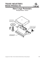
New Large Pedestals
Example Shown - Avalon
Pedestal Attachment
NOTE: If using outside air, install it prior to attaching the pedestal (see Outside Air Installation on page 2 and 3).
Stove
9/16" Wrench
Two pedestal bolts
attach the pedestal to
the bottom of the stove.
The dowels insert onto
the front and back edge
of the pedestal base.
The lag bolts and washers
may be inserted through
these holes to anchor the
pedestal to the floor.
Pedestal
Copyright © 3/17/2008 - Travis Industries Certified Factory Training Program
39
TRAVIS INDUSTRIES
WOOD PRODUCTS
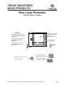
New Large Pedestals
Example Shown - Avalon
Using Outside Air with the Rainier & Olympic Wood Stoves
The following outside air knock-out must be removed and the cover plate installed when using outside air with
the Rainier or Olympic wood stoves.
The outside air knock-out must be removed on the Rainier (45 or 90) and Olympic. See the illustration below.
Knock-Out for
FRONT OF STOVE
Outside Air Knock-Out for
Standard Pedestals
the Ash Pan
Pedestal Drop
Chute
Outside Air Knock-Out for Stoves on Legs
or Stoves Using Ash Pan Pedestal
Rear Blower Knock-Outs
Install the included cover plate so air is drawn from below, not the front. See the directions below.
Remove the two screws on the
cover plate to remove the piece that
fits over the air control rod. Then
replace the piece when the cover
Air Control Rod
plate is in place.
The cover plate has a clip which attaches
it underneath the air control.
Copyright © 3/17/2008 - Travis Industries Certified Factory Training Program
40
TRAVIS INDUSTRIES
WOOD PRODUCTS
New Large Pedestals
Example Shown - Avalon
Outside Air Installation – Using the Outside Air Kit (99200139)
a
Tuck insulation (included with the
pedestal) under both sides of the
pedestal and under the holes on the
base of the pedestal. This prevents air
from being
drawn from below
the pedestal.
Select a location between
framing members for the
wall penetration.
NOTE: If wall is thicker
than 8", attach the flex duct
to the hood then slide the
hood into place.
b Remove the cover
plate on the pedestal.
Seal the area around
the tube to prevent
air from entering
through the wall.
c
Slide the hood
through the wall and
secure to the outside
Cover Plate
wall with the two
included screws.
Sil
ico
ne
Silico
ne
3" Dia. Flex Duct
(4' max. length)
e
Secure the flex duct to the
air duct assembly using
the included hose clamp.
Attach the outside air duct
assembly to the pedestal
with the same screws that
held the cover plate in
place.
Min. 3"
Dia. Hole
d
Slide the cover plate over the flex duct
then attach the flex duct to the hood with
the included hose clamp. Secure the
cover plate to the wall with the included
screws (and drywall anchors if needed).
HINT: The flex must be fully stretched and
the ends cut square and flatted for it to fit
properly. The tube on the hood and air
duct may be crimped if necessary.
8"
Hood with Rodent Screen
Copyright © 3/17/2008 - Travis Industries Certified Factory Training Program
41
TRAVIS INDUSTRIES
WOOD PRODUCTS
New Large Pedestals
Example Shown - Avalon
Outside Air Installation – Through the Pedestal into the Crawl Space
This pedestal has an internal air duct that may be used to direct air to the firebox. Outside air is then drawn from
the crawl space under the stove (check with local building codes for requirements in your area). See the
directions below for installation details.
1
Determine the location of the hole placed under the pedestal. The illustration below details the location of the
pedestal in relation to the front of the stove. The hole should be at least 16 square inches.
Top View
26"
The faceplate of the Rainier (45/90) is
1-1/2" behind the forward edge of the
pedestal base.
Outside air may be drawn
from this area underneath
the pedestal
(min. 16 square inches)
16"
The faceplate of the Olympic is 1/4" in
front of the forward edge of the
pedestal base.
The faceplate of the 1750 is 2-1/2" in
front of the forward edge of the
pedestal base.
2
19-3/4"
Pedestal Base
(with dowels)
17"
FRONT
Attach the included screen over the hole (staples are included with the pedestal). Tuck insulation under both
sides of the pedestal and under the holes in the base of the pedestal (see step “a” on the page 2). This
prevents air from entering under the pedestal.
Screen is used to prevent
Insulation is used to seal the side
edges of the pedestal .
rodents from entering.
Staples are used to attach
the screen to the floor.
3
Attach the stove to the pedestal.
Copyright © 3/17/2008 - Travis Industries Certified Factory Training Program
42
TRAVIS INDUSTRIES
WOOD PRODUCTS
Pedestal - Avalon Ashpan
Copyright © 3/17/2008 - Travis Industries Certified Factory Training Program
43
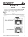
TRAVIS INDUSTRIES
WOOD PRODUCTS
Mantle Shield
Copyright © 3/17/2008 - Travis Industries Certified Factory Training Program
44
TRAVIS INDUSTRIES
WOOD PRODUCTS
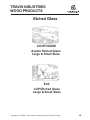
Etched Glass
LIGHTHOUSE
Avalon Etched Glass
Large & Small Sizes
ELK
LOPI Etched Glass
Large & Small Sizes
Copyright © 3/17/2008 - Travis Industries Certified Factory Training Program
45
TRAVIS INDUSTRIES
WOOD PRODUCTS
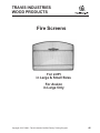
Fire Screens
For LOPI
in Large & Small Sizes
For Avalon
in Large Only
Copyright © 3/17/2008 - Travis Industries Certified Factory Training Program
46
TRAVIS INDUSTRIES
WOOD PRODUCTS
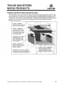
Panels
Copyright © 3/17/2008 - Travis Industries Certified Factory Training Program
47
TRAVIS INDUSTRIES
WOOD PRODUCTS
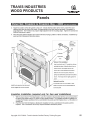
Panels
Copyright © 3/17/2008 - Travis Industries Certified Factory Training Program
48
TRAVIS INDUSTRIES
WOOD PRODUCTS
Panels
Copyright © 3/17/2008 - Travis Industries Certified Factory Training Program
49
TRAVIS INDUSTRIES
WOOD PRODUCTS
Panels
Copyright © 3/17/2008 - Travis Industries Certified Factory Training Program
50
TRAVIS INDUSTRIES
WOOD PRODUCTS
Panels
Copyright © 3/17/2008 - Travis Industries Certified Factory Training Program
51
TRAVIS INDUSTRIES
WOOD PRODUCTS
Panels
Copyright © 3/17/2008 - Travis Industries Certified Factory Training Program
52
TRAVIS INDUSTRIES
WOOD PRODUCTS
Panels
Copyright © 3/17/2008 - Travis Industries Certified Factory Training Program
53
TRAVIS INDUSTRIES
WOOD PRODUCTS
Panels
Copyright © 3/17/2008 - Travis Industries Certified Factory Training Program
54
TRAVIS INDUSTRIES
WOOD PRODUCTS
Panels
Copyright © 3/17/2008 - Travis Industries Certified Factory Training Program
55
TRAVIS INDUSTRIES
WOOD PRODUCTS
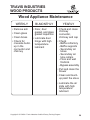
Wood Appliance Maintenance
WEEKLY
BI-MONTHLY
YEARLY
• Remove ash
• Door, door
• gasket, and glass
• gasket inspection
• Check and clean
• chimney • • • • • •
• connector, • • • • •
• chimney and cap
• Clean glass
• Clean brass
• Check for
• creosote build• up in the • • •
• connector and
chimney
• Lubricate door •
• hinge with high
• temperature • • •
• lubricant
• Check
- Baffle refractory
- Baffle supports
- Secondary air
- tubes
- Secondary air
- tube collars
- Floor and wall
- firebrick
- Bypass assembly
• Pull and clean the
• blower
• Clean and touch• up paint the stove
• Lubricate the air •
• slide with high •
• temperature • • •
• lubricant
Copyright © 3/17/2008 - Travis Industries Certified Factory Training Program
56
TRAVIS INDUSTRIES
WOOD PRODUCTS
Copyright © 3/17/2008 - Travis Industries Certified Factory Training Program
57
TRAVIS INDUSTRIES
WOOD PRODUCTS
Copyright © 3/17/2008 - Travis Industries Certified Factory Training Program
58
TRAVIS INDUSTRIES
WOOD PRODUCTS
Copyright © 3/17/2008 - Travis Industries Certified Factory Training Program
59
TRAVIS INDUSTRIES
WOOD PRODUCTS
Copyright © 3/17/2008 - Travis Industries Certified Factory Training Program
60
TRAVIS INDUSTRIES
WOOD PRODUCTS
Copyright © 3/17/2008 - Travis Industries Certified Factory Training Program
61
TRAVIS INDUSTRIES
WOOD PRODUCTS
Copyright © 3/17/2008 - Travis Industries Certified Factory Training Program
62
TRAVIS INDUSTRIES
WOOD PRODUCTS
Copyright © 3/17/2008 - Travis Industries Certified Factory Training Program
63
TRAVIS INDUSTRIES
WOOD PRODUCTS
• New roll pins to hold air tube
• Hammer in to install
• Drive through into air tube to remove
Copyright © 3/17/2008 - Travis Industries Certified Factory Training Program
64
TRAVIS INDUSTRIES
WOOD PRODUCTS
Copyright © 3/17/2008 - Travis Industries Certified Factory Training Program
65
TRAVIS INDUSTRIES
WOOD PRODUCTS
Copyright © 3/17/2008 - Travis Industries Certified Factory Training Program
66
FPX
WOOD FIREPLACES
Wood Burning Fireplaces
Catalytic Maintenance
Wood Fireplace Installation
Copyright © 3/17/2008 - Travis Industries Certified Factory Training Program
67
FPX
WOOD FIREPLACES
Copyright © 3/17/2008 - Travis Industries Certified Factory Training Program
68
FPX
WOOD FIREPLACES
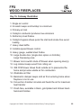
Key To Cutaway Illustration
1. Single air control
2. Air wash keeps soot buildup to a minimum
3. Primary air inlet
4. Catalytic combustor produces low emissions
5. Refractory lined firebox
6. Catalytic bypass allows quick fire start and smoke free wood
loading
7. Heavy steel baffle
8. Variable speed blower control
9. Heavy gauge, welded steel firebox
10. Large double door (single door option on 36 Elite)
10. Large fireviewing area
11. Blower micro switch shuts off blower when opening door(s)
12. Log retainer keeps wood from rolling out
13. 388 CFM blower draws fresh outside air to pressurize the
13. home and provide outside air for combustion
14. Washable air filter
15. Barometric damper keeps cold air from entering home when
15. fireplace is not in use
16. Convection chamber circulate and heats the air for maximum
heat transfer
17. Finish face, available in black, gold plated and Artisan hand17. hammers finishes
Copyright © 3/17/2008 - Travis Industries Certified Factory Training Program
69
FPX
WOOD FIREPLACES
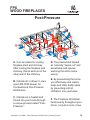
Posi-Pressure
A. Cool air intake for cooling
fireplace shell and chimney.
After cooling the fireplace and
chimney, this air exits out of the
other wall of the chimney.
D. The pressurized heated
air naturally "seeks out" and
penetrates cold spaces,
warming the entire home
evenly.
B. Outside Air is drawn in via a
quiet 388 CFM blower, for
Combustion & Posi-Pressure
Distribution.
E. By pressurizing the home
you effectively seal cracks,
leaks and other drafty spots
by preventing cold air
infiltration into your home.
C. Outside air is heated and
forced into your home through
a unique process called "PosiPressure.”
F. The Fireplace Xtrordinair
heats evenly throughout your
home, not just a room or two.
Copyright © 3/17/2008 - Travis Industries Certified Factory Training Program
70
FPX
WOOD FIREPLACES
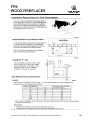
Catalytic Combustor
Catalytic
Combustor
• Honeycomb • • •
• Ceramic
• Due to the huge firebox size, •
• a catalytic combustor is used to
• clean up the smoke as it leaves
• the fireplace.
• Coated With
• Noble Metal
• Combustors are a honey-• • • •
• combed ceramic material.
• Reduces Ignition
• Temperature of •
• Smoke By 50%
• The ceramic is coated with a •
• noble metal which decreases •
• the ignition temperature of the
• smoke passing through it by • •
• 50%.
• The metal that is used for the •
• coating is Platinum or Palladium.
NEVER BURN
WOOD WITH
GALVANIZED
NAILS!
Will Cause the
combustor to
explode
• Care must be taken not to burn
• colored newsprint, foam cups,
• paper plates, trash, etc.
••
These material will quickly plug
up and damage the combustor.
• CAUTION: The combustor will
• become brittle with time. • • • •
• Handle it with care.
Copyright © 3/17/2008 - Travis Industries Certified Factory Training Program
71
FPX
WOOD FIREPLACES
Copyright © 3/17/2008 - Travis Industries Certified Factory Training Program
72
FPX
WOOD FIREPLACES
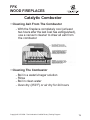
Catalytic Combustor
• Cleaning Ash From The Combustor
- With the fireplace completely cool (at least
two hours after the last coal has extinguished),
use a vacuum cleaner to draw all ash from
the combustor
• Cleaning The Combustor
- Boil in a water/vinegar solution
- Rinse
- Boil in clean water
- Oven dry (350˚F) or air dry for 24 hours
Copyright © 3/17/2008 - Travis Industries Certified Factory Training Program
73
FPX
WOOD FIREPLACES
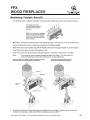
Replacing Catalytic Combustor
36 Elite & 44 Elite
Copyright © 3/17/2008 - Travis Industries Certified Factory Training Program
74
FPX
WOOD FIREPLACES
Copyright © 3/17/2008 - Travis Industries Certified Factory Training Program
75
FPX
WOOD FIREPLACES
Copyright © 3/17/2008 - Travis Industries Certified Factory Training Program
76
FPX
WOOD FIREPLACES
Mantel Requirements
•
•
•
The optional mantel must be a minimum 23" above the top of the faceplate (61" above the base)
The mantel must not extend more than 8-1/2" in front of the faceplate.
Mantel side columns that protrude more than 3/4" must maintain an 18" clearance to the faceplate
Hearth Requirements
?
•
•
•
•
Local building codes may require a minimum
hearth requirement different of what this
manual states
Hearth must extend 20" in front of the
faceplate when it is not elevated (see local
building codes). Hearths raised 6-1/2" must
extend a minimum 18".
Hearth must extend a minimum 8" to both
sides of the faceplate (60" wide)
Hearth must be a minimum 1" thick of
cement board (or equivalent)
Hearth must not rise more than 6-1/2" above
the base of the fireplace
23"
Mantel (may be
combustible)
Minimum
Mantel
Clearance
Minimum
Hearth
Width = 60"
20" (18" in
some cases)
8" Min.
Minimum 1" cement board
Faceplate
Fireplace
Tile or
marble
No combustible material
permitted above this point
Fireplace
Elevated hearths must be
constructed of non-combustible
materials such as cement blocks
(6-1/2” Max.).
Tile or
marble
2 x 4 Framing
Ember
Strip
Header height will
need to be increased
this dimension.
3/4"
Plywood
15"
Raised
hearth
Ember
Strip
Header height needs to be
increased this dimension.
3/4"
Plywood
15"
Raised
hearth
2 x 8 Framing
Faceplate
Fireplace
Faceplate
18" Min.
(Check Local Building Codes)
Fireplace
Combustible Floor
20" Min.
(Check Local Building Codes)
6 1/2"
Max.
Ember
Strip
No hearth material can
go above this point
Combustible
Floor
Ember
Strip
Min. 1" cement board
(or equivalent)
Copyright © 3/17/2008 - Travis Industries Certified Factory Training Program
Tile or
marble
77
FPX
WOOD FIREPLACES
Raised Fireplaces
•
If the fireplace is raised more than 15” above the sub-floor, the fireplace
enclosure will have to be raised accordingly (see “Minimum Framing
Dimensions” on page 3).
+ The fireplace may be placed on a platform designed to support the fireplace and vent
(Approximately 600 Lbs.).
Minimum 1" cement board
Faceplate
Fireplace
Tile or
marble
No combustible material
permitted above this point
Fireplace
Elevated hearths must be
constructed of non-combustible
materials such as cement blocks
(6-1/2” Max.).
Tile or
marble
2 x 4 Framing
Ember
Strip
Header height will
need to be increased
this dimension.
3/4"
Plywood
15"
Raised
hearth
Ember
Strip
Header height needs to be
increased this dimension.
3/4"
Plywood
15"
Raised
hearth
2 x 8 Framing
Facing Requirements
NOTE:
•
•
•
•
•
Artisan faces vary in size. If the facing is over 1” thick (brick, riverrock, etc.) use the face being installed to create a template.
The fireplace is shipped with a set-up face that is 1/16" larger on the top, bottom and each side than
the faceplate. Leave the set-up face in place to act as a template when installing the facing.
The fireplace requires 1/2" thick concrete-board or other non-combustible to extend from the header
to the base of the fireplace and to the framing members on both sides (do not use sheetrock or
drywall).
The non-combustible facing must extend a minimum of 12" above and 2-1/2" to each side of the
faceplate.
The non-combustible facing must be a minimum 1" thick
The facing may be attached to the front of the fireplace with screws. Do not penetrate the fireplace
more than 3/4”.
Cement-board must
extend from the header
to the floor and to the
framing members on
both sides.
12" (min.)
Non-combustible
Facing
2-1/2"
(min.)
•
Keep the set-up face
on the fireplace when
installing the facing.
Facing may be installed so it inserts behind the faceplate. NOTE: the faceplate protrudes 1" from the
front of the fireplace, has a 1/8" overlap on the sides, and 1/4" overlap on top.
Copyright © 3/17/2008 - Travis Industries Certified Factory Training Program
78
FPX
WOOD FIREPLACES
Copyright © 3/17/2008 - Travis Industries Certified Factory Training Program
79
FPX
WOOD FIREPLACES
Copyright © 3/17/2008 - Travis Industries Certified Factory Training Program
80
FPX
WOOD FIREPLACES
Copyright © 3/17/2008 - Travis Industries Certified Factory Training Program
81
FPX
WOOD FIREPLACES
Copyright © 3/17/2008 - Travis Industries Certified Factory Training Program
82
FPX
WOOD FIREPLACES
Copyright © 3/17/2008 - Travis Industries Certified Factory Training Program
83
FPX
WOOD FIREPLACES
Copyright © 3/17/2008 - Travis Industries Certified Factory Training Program
84
TRAVIS 564
ELECTRIC FIREPLACE FACES
Avalon Electric Fireplace -Seattle E
Basic Frame or choose from one of these designer faces
Victorian Lace
Face
Black Painted
Victorian Lace
Face
Black Nickel
Palted with
Nickel Accents
Bungalow Face
Black
Textured Steel
Lopi Electric Fireplace -Bostonian E
Basic Frame or choose from one of these designer faces
Wilmington Face
Black Painted
Wilmington Face
BlackPainted
Arabesque Grills
WilmingtonFace
PewterPlated
Wilmington Face
PewterPlated
Arabesque Grills
FPX Electric Fireplace -Model 564 E
Basic Frame or choose from one of these designer faces
Classic Arch
Black
Metropolitan
Black Painted
French Country
Antique Gold
Artisan
Charcoal Painted
Copyright © 3/17/2008 - Travis Industries Certified Factory Training Program
Matrix
Brushed Nickel
85
TRAVIS
ELECTRIC FIREPLACES
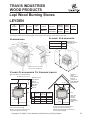
564 E
ELECTRIC FIREPLACES
• Dimplex™ licensed technology with Travis Industries face designs
• Fabricated steel firebox featuring patented flame technology
• Realistic wood-like flame
• Instant ambiance of a real fireplace to any living area in just minutes
• Safe clean operation - stay cool glass, no combustibles to vent
• Effective heat - Thermostatically controlled 1500W fan provides
supplemental heat for up to 400 sq. ft.
• Plug and Play - simply plug into any 110v outlet
• Clean air purification system - filters your rooms (12’ x 14’) air
four time per hour
• Variable speed flame image
• Pulsing, glowing logs and ember bed
• Brick liner appearance
• Variable interior light
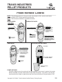
• Multi-function Remote Control:
1. Flame On/Off
2. Clean Air On/Off
3. Flame Speed
4. Interior Accent Light
5. Room Temperature Monitor
6. Set Temperature
7. Sleep Timer
• Year-round enjoyment of the fire
Copyright © 3/17/2008 - Travis Industries Certified Factory Training Program
86
TRAVIS
ELECTRIC FIREPLACES
564 E FIREPLACES
Copyright © 3/17/2008 - Travis Industries Certified Factory Training Program
87
TRAVIS
ELECTRIC FIREPLACES
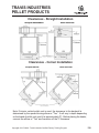
564 E FIREPLACE FRAMING
Copyright © 3/17/2008 - Travis Industries Certified Factory Training Program
88A
TRAVIS
ELECTRIC FIREPLACES
564 E FIREPLACE MANTELS
Avaliable From Travis Industries
Mantel, 564 E Oak Finish
Sku # 96900911
Mantel, 564 E Walnut Finish
Sku # 96900913
Mantel, 564 E Cherry Finish
Sku # 96900915
Copyright © 3/17/2008 - Travis Industries Certified Factory Training Program
88B
TRAVIS
ELECTRIC FIREPLACES
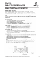
564 E FIREPLACE OPERATION
Copyright © 3/17/2008 - Travis Industries Certified Factory Training Program
89
TRAVIS
ELECTRIC FIREPLACES
564 E FIREPLACE REMOTE
Copyright © 3/17/2008 - Travis Industries Certified Factory Training Program
90
TRAVIS
ELECTRIC FIREPLACES
564 E FIREPLACE REMOTE
Copyright © 3/17/2008 - Travis Industries Certified Factory Training Program
91
TRAVIS
ELECTRIC FIREPLACES
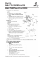
564 E FIREPLACE ACCESS
Copyright © 3/17/2008 - Travis Industries Certified Factory Training Program
92
TRAVIS
ELECTRIC FIREPLACES
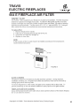
564 E FIREPLACE AIR FILTER
Copyright © 3/17/2008 - Travis Industries Certified Factory Training Program
93
TRAVIS INDUSTRIES
PELLET PRODUCTS
Pellet Stoves & Inserts
Pellet Venting
Pellet Restrictors
Pellet Maintenance
Wood & Pellet Installation
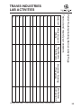
Wood & Pellet Lab Activities
Installation Lab Activities
Copyright © 3/17/2008 - Travis Industries Certified Factory Training Program
94
TRAVIS INDUSTRIES
PELLET PRODUCTS
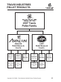
2007 Travis
Pellet Family
AVALON
Pellet Stoves &
Inserts
AVALON
Newport Bay
Mid-Sized
Pellet
AVALON
Newport
Mid-Sized
Pellet Stove
AVALON
Astoria Bay
Large
Pellet Insert
AVALON
Astoria
Large Pellet
Stove
Avalon
Arbor
Mid-Sized
Cast Pellet
Stove
LOPI
Pellet Stoves &
Inserts
LOPI
Pioneer Bay
Mid-Sized
Pellet Insert
LOPI
Pioneer
Mid-Sized
Pellet Stove
LOPI
Yankee Bay
Large Pellet
Insert
LOPI
Yankee
Large Pellet
Stove
Copyright © 3/17/2008 - Travis Industries Certified Factory Training Program
LOPI
Leyden
Mid-Sized
Cast Pellet
Stove
95
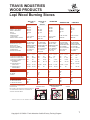
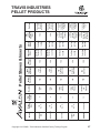
800 1,600
Sq. Ft
NEWPORT
Copyright © 3/17/2008 - Travis Industries Certified Factory Training Program
ARBOR
ASTORIA
BAY
ASTORIA
800 1,600
Sq. Ft
NEWPORT
BAY
800 - 2,250
Sq. Ft
800 - 2,250
Sq. Ft
800 - 2,250
Sq. Ft
Square
Feet
Heating
Space
Pellet
Appliance
Low
9,600
High
28,000
Low
13,940
High
45,100
Low
13,940
High
45,100
Low
13,940
High 3.5
Lbs./Hr.
Low 1.2
Lbs./Hr.
High 5.5
Lbs./Hr.
Low 1.7
Lbs./Hr.
High 5.5
Lbs./Hr.
Low 1.7
Lbs./Hr.
High 5.5
Lbs./Hr.
High
45,100
High
28,000
Low 1.2
Lbs./Hr.
Low 1.7
Lbs./Hr.
High
10 Hours
Low
9,600
High 3.5
Lbs./Hr.
High
15 Hours
Low
47 Hours
High
10 Hours
Low
32 Hours
High
21 Hours
Low
67 Hours
High
15 Hours
Low
50 Hours
Low
29 Hours
BTU’s
Range
Burn
Rate
Burn
Time
Up to 82%
Up to 82%
Up to 82%
Up to 82%
Up to 82%
Efficiency
96
3.6 AMPS
180 W Operation
400 W - Start
Up
3.6 AMPS
180 W Operation
400 W - Start
Up
3.6 AMPS
180 W Operation
400 W - Start
Up
3.6 AMPS
180 W Operation
400 W - Start
Up
3.6 AMPS
180 W Operation
400 W - Start
Up
Electrical
Usage
YES
1,500˚ F
YES
1,500˚ F
YES
1,500˚ F
YES
1,500˚ F
YES
1,500˚ F
Automatic
Igniter
Pellet Stoves & Inserts
47 Lbs.
55 Lbs.
115 Lbs.
55 Lbs.
35 Lbs.
Hopper
Capacity
Class A Retro
Mobile Home
Horizontal &
Vertical
Class A
Retro
Mobile Home
Horizontal &
Vertical
Class A
Retro
Mobile Home
Horizontal &
Vertical
Class A Retro
Mobile Home
Horizontal &
Vertical
4”
4”
4”
4” at High
Elevations or
Tall Vertical
Terminations
3”
4” at High
Elevations or
Tall Vertical
Terminations
3”
Horizontal &
Vertical
Class A Retro
Masonry
ZC
Mobile Home
Venting
Size
Installation
Approvals
TRAVIS INDUSTRIES
PELLET PRODUCTS
Heat
Exchanger
Tubes
6
6
10
12
12
Glass
Viewing
Area
167
Sq. In.
167
Sq. In.
321
Sq. In.
321
Sq. In.
308 Sq. In.
Model
NEWPORT
BAY
NEWPORT
ASTORIA
ASTORIA
Bay
Copyright © 3/17/2008 - Travis Industries Certified Factory Training Program
ARBOR
YES
Intake
Air &
Exhaust
Exhaust
YES
YES
Intake
Air &
Exhaust
Intake Air
and
YES
YES
Manual
Operation
Intake
Air
Intake
Air
Restrictor
YES
YES
Optional
YES
Standard
YES
Standard
with Astoria
YES
YES
YES
YES
YES
Optional
YES
Standard
with Astoria
Remote
Operation
Wall
Thermostat
Operation
75 CFM
130 CFM
92 CFM
165 CFM
Gold or Nickel
Door, Gold
Convection
Grill, Log Set
Gold or Nickel
Door, Gold
Convection
Grill, Log Set
Options
Universal Log
with Modified
Holder
YES
Gold or Nickel
Door &
Curved
Convection Grill,
Bottom
Universal Log
Wide Flame with Modified
Holder
Dispersal
YES
Gold or Nickel
Curved
Door &
Bottom
Convection Grill,
Wide Flame Universal Log
with Modified
Dispersal
Holder
YES
YES
3/16”
309
Stainless
Steel Burn
Pot
YES
Curved
Centrifugal Centrifugal
Bottom for
92 CFM
165 CFM
Wide Flame
Dispersal
Centrifugal
92 CFM
Centrifugal
165 CFM
Centrifugal
Centrifugal
Cross Flow
Transaxial
Centrifugal
75 CFM
Centrifugal
Cross Flow
Transaxial
130 CFM
Exhaust
Blower
Convection
Blower
Pellet Stoves & Inserts
TRAVIS INDUSTRIES
PELLET PRODUCTS
97
800 1,600
Sq. Ft
PIONEER
BAY
PIONEER
Copyright © 3/17/2008 - Travis Industries Certified Factory Training Program
LEYDEN
YANKEE
BAY
YANKEE
800 1,600
Sq. Ft
800 - 2,250
Sq. Ft
800 - 2,250
Sq. Ft
800 - 2,250
Sq. Ft
Square
Feet
Heating
Space
Pellet
Appliance
High
10 Hours
Low
9,600
High
28,000
Low
9,600
High
28,000
Low
13,940
High
45,100
Low
13,940
High
45,100
Low
13,940
High
45,100
High 3.5
Lbs./Hr.
Low 1.2
Lbs./Hr.
High 3.5
Lbs./Hr.
Low 1.2
Lbs./Hr.
High 5.5
Lbs./Hr.
Low 1.7
Lbs./Hr.
High 5.5
Lbs./Hr.
Low 1.7
Lbs./Hr.
High 5.5
Lbs./Hr.
Low 1.7
Lbs./Hr.
High
15 Hours
Low
47 Hours
High
10 Hours
Low
32 Hours
High
15 Hours
Low
47 Hours
High
15 Hours
Low
50 Hours
Low
29 Hours
BTU’s
Range
Burn
Rate
Burn
Time
Up to 82%
Up to 82%
Up to 82%
Up to 82%
Up to 82%
Efficiency
3.6 AMPS
180 W Operation
400 W - Start
Up
3.6 AMPS
180 W Operation
400 W - Start
Up
3.6 AMPS
180 W Operation
400 W - Start
Up
3.6 AMPS
180 W Operation
400 W - Start
Up
3.6 AMPS
180 W Operation
400 W - Start
Up
Electrical
Usage
Pellet Stoves & Inserts
YES
1,500˚ F
YES
1,500˚ F
YES
1,500˚ F
YES
1,500˚ F
YES
1,500˚ F
Automatic
Igniter
Wood
Pellets
or 50/50 Mix
Wood and
Corn
Wood
Pellets
Wood
Pellets
Wood
Pellets
Wood
Pellets
Approved
Fuel
47 Lbs.
55 Lbs.
80 Lbs.
55 Lbs.
35 Lbs.
Hopper
Capacity
Class A Retro
Mobile Home
Horizontal &
Vertical
Class A Retro
Mobile Home
Horizontal &
Vertical
Class A Retro
Mobile Home
Horizontal &
Vertical
Class A Retro
Mobile Home
Horizontal &
Vertical
Class A Retro
Masonry
ZC
Mobile Home
3”
Horizontal &
Vertical
4”
4”
4”
4” at High
Elevations or
Tall Vertical
Terminations
3”
4” at High
Elevations or
Tall Vertical
Terminations
Venting
Size
Installation
Approvals
TRAVIS INDUSTRIES
PELLET PRODUCTS
98
Copyright © 3/17/2008 - Travis Industries Certified Factory Training Program
12
308 Sq. In.
LEYDEN
Exhaust
Intake Air
and
Exhaust
YES
YES
10
252 Sq. In.
YANKEE
BAY
Intake Air
and
Exhaust
YES
12
252 Sq. In.
YANKEE
Intake Air
and
YES
Manual
Operation
YES
Intake Air
Restrictor
Intake Air
167 Sq. In.
PIONEER
6
Heat
Exchanger
Tubes
6
167 Sq. In.
Glass
Viewing
Area
PIONEER
BAY
Pellet
Appliance
YES
Standard
YES
Standard
YES
Standard
YES
YES
YES
YES
YES
YES
Optional
YES
Optional
Remote
Contrl
Operation
Wall
Thermostat
Operation
Pellet Stoves & Inserts
Centrifugal
165 CFM
Centrifugal
165 CFM
Centrifugal
165 CFM
Crossflow
Transaxial
130 CFM
Crossflow
Transaxial
130 CFM
Convection
Blower
Centrifugal
92 CFM
Centrifugal
92 CFM
Centrifugal
92 CFM
Centrifugal
75 CFM
Centrifugal
75 CFM
Exhaust
Blower
Gold or Pewter
Door &
Convection Grill,
Universal Log
with Modified
Holder
Gold or Pewter
Door &
Convection Grill,
Universal Log
with Modified
Holder
Universal Log
with Modified
Holder
YES
Curved
Bottom for
Wide Flame
Dispersal
YES
Curved
Bottom for
Wide Flame
Dispersal
Gold or Pewter
Door &
Convection Grill,
Universal Log
with Modified
Holder
Gold or Pewter
Door &
Convection Grill,
Universal Log
with Modified
Holder
Options
YES
Curved
Bottom for
Wide Flame
Dispersal
YES
YES
3/16” 309
Stainless
Steel Burn
pot
TRAVIS INDUSTRIES
PELLET PRODUCTS
99
TRAVIS INDUSTRIES
PELLET PRODUCTS
Features of Travis Brand Pellet
Stoves and Inserts
• “Real World” Seven Year Warranty
• Small and Large Heating
• Capacities
• 800 to 1,600 Sq. Ft. Heating
• Capacity
•
• Large Hopper Capacity
• Horizontal or Vertical
••••••
• Termination Flue Options
• Outside Air kit
• Gravity Flow Feed
• Minimal Clearances to
• Combustibles
• Heavy-Duty Auger Shaft
• and Flight
• Minimal Floor Protection
• Requirements
• Removable Auger Cover
• Easy Access Components
• Self-Lubricating Bronze Auger
• Bearings
• Fuse Protected Systems
• Heavy-Duty Auger Motor
• Heat Exchanger Ash Rake • • •
• Cleaner
• No Tools Requires for Cleaning
• 3/16” Stainless Steel Firepot
• Cast Iron Fireback
• Air Tight Door Seal
• Airwash Keeps Glass Clear
• Options of Black, Gold Door &
• Nickel Door - Avalon
Pewter Door - Lopi
• Operation Instructions on Inside
of Lid
•••••
• Inserts Masonry and ZC
• Approved
•••
••••
• Adjustable Door
• Spring Loaded Rails on
Ash Dump
• Hopper Safety Snap Disc
• Flow Safety Snap Disk
• Quiet Operation
• Automatic ignition
• Thermostat/Remote Control
• Option
• Auto or Manual Operation
• Option
•
••
• Single Control Feed/Air Control
Copyright © 3/17/2008 - Travis Industries Certified Factory Training Program
100
TRAVIS INDUSTRIES
PELLET PRODUCTS
Features of Avalon Arbor
Cast Iron Pellet Stove
Features:
• Medium-size pellet stove.
• Black painted cast iron design of the wood • •
• burning Leyden
• Organic tree cast iron detail.
• Unique burn pot designed to burn wood pellets
• or a 50/50 mix of wood pellets and corn.
• Most efficient heat exchange system of any •
• Avalon pellet stove.
• Cast double doors with large fireview.
• Self-starting ignitor standard.
• Ash Glide Ash Pan:
• Whisper quiet performance - variable • • • • • •
• combustion fan synchronized with adjustable
• burn rate.
- Most convenient ash removal system on
- the market, no special tool needed.
- Large ash holding capacity.
• Wall thermostat standard.
• Uses a 4” chimney.
• EPA Exempt.
• Stay clean airwash.
• Uses same pellet components found in the
• Yankee pellet stove.
• Stainless-steel burn pot removes easily for • •
• cleaning.
• Will have same performance statistics as
• the Astoria.
• Electronic control board for manual or automatic
• operation with use of low voltage thermostat or
• programmable wall thermostat or remote control.
• 47 lbs. hopper.
Copyright © 3/17/2008 - Travis Industries Certified Factory Training Program
101
TRAVIS INDUSTRIES
PELLET PRODUCTS
Features of LOPI Leyden Cast Iron Pellet Stove
Features:
• Medium-size pellet stove.
• Black painted cast iron design of the wood • •
• burning Leyden
• Early-American architectural cast iron detail.
• Unique burn pot designed to burn wood pellets
• or a 50/50 mix of wood pellets and corn.
• Most efficient heat exchange system of any •
• Lopi pellet stove.
• Cast double doors with large fireview.
• Self-starting ignitor standard.
• Ash Glide Ash Pan:
• Whisper quiet performance - variable • • • • • •
• combustion fan synchronized with adjustable
• burn rate.
- Most convenient ash removal system on
- the market, no special tool needed.
- Large ash holding capacity.
• Wall thermostat standard.
• Uses a 4” chimney.
• EPA Exempt.
• Stay clean airwash.
• Uses same pellet components found in the
• Yankee pellet stove.
• Stainless-steel burn pot removes easily for • •
• cleaning.
• Will have same performance statistics as
• the Yankee.
• Electronic control board for manual or automatic
• operation with use of low voltage thermostat or
• programmable wall thermostat or remote control.
• 47 lbs. hopper.
Copyright © 3/17/2008 - Travis Industries Certified Factory Training Program
102
TRAVIS INDUSTRIES
PELLET PRODUCTS
Pellet Appliance Components
When designing pellet appliances the following
considerations need to take place.
Safety - The appliance must be designed to contain fire
and keep the fuel in the pellet hopper from catching on
fire.
Efficiency - Today’s heating costs push the public to
demand efficient economical appliance operation.
Styling - Appliance appearance and customer choice are
an important consideration of the appliance purchase.
Quality - Today’s consumer expects top quality for many
years of operation.
Easy to operate - Consumers want simple easy-to-operate
(consumer friendly) appliances.
Easy to service and maintain - Consumers and service
people demand simple easy serviceability.
Quiet operation - A pellet appliance has the potential of
being very noisy. Two blowers, auger motor, auger flight
and dropping pellets can be very distracting. Therefore,
dampening vibration devices have to be incorporated into
the appliance design.
Copyright © 3/17/2008 - Travis Industries Certified Factory Training Program
103
TRAVIS INDUSTRIES
PELLET PRODUCTS
Pellet Appliance Components
• Pellet Hopper
- Angled to ensure
- non-bridging gravity feed
- Aluminized steel
- construction
- Large capacities
• Auger
- 3/4” steel shaft
- 1 1/4” pitch spacing
- (small stoves)
- 2” pitch
- spacing (large stoves)
- Easy, removable access
- cover
- Sintered bronze bearings
• Auger Motor
- Merkl Korff motor
- Turns at 1 RPM
- Impedance
- protected to prevent burnout
- if the auger freezes up
- Rubber stops for
- quiet operation
When looking at output
shaft, it turns clockwise
Copyright © 3/17/2008 - Travis Industries Certified Factory Training Program
104
TRAVIS INDUSTRIES
PELLET PRODUCTS
Pellet Appliance Components
• Control Board
- Remote, automatic, and manual selection
- Remote and thermostat ready
- Single control air/feed rate
- LED panel display
- Fuse protected
• Flow Switch
- Senses vacuum from
- exhaust blower
- N.O. switch
- Wires in series with
- the auger circuit
• Snap Disk
System
Snap Disc
Hopper Snap Disc
- Set point 200˚ F
- N.C. switch
- Large stove uses (2)
- Wires in series with
- auger circuit
- Senses heat (pellets are burning)
- Large stove - mounted on exhaust blower
- Small stove mounted on horizontal
- exhaust port
- Set point 120˚ F
- N.O. switch
- Large stove uses (2)
Copyright © 3/17/2008 - Travis Industries Certified Factory Training Program
105
TRAVIS INDUSTRIES
PELLET PRODUCTS
Pellet Appliance Components
• Convection Blower
Small Pellet Stoves
- 130 CFM
- Cross flow transaxial blower
- Cushion mounting vibration control
• Exhaust Blower
Large Pellet Stoves
- 165 CFM
- Centrifugal blower
- Cushion mounting for vibration
control
Small Pellet Stoves
- 75 CFM
- Centrifugal blower
- Cushion
- mounting for
- vibration control
Large Pellet Stoves
- 92 CFM
- Centrifugal blower
- Cushion
- mounting for
- vibration control
• Igniter
- 110 volt
- Heats to 1500˚ F
- Sheath on large
-stoves 1/2” longer
Copyright © 3/17/2008 - Travis Industries Certified Factory Training Program
10-6
TRAVIS INDUSTRIES
PELLET PRODUCTS
Pellet Appliance Components
• Log Set
- Optional universal
- cast log
- Large stoves use
-a modified holder
• Burn Pot
- Stainless steel burn pot
- Bottom 3/16” - Type 309 Stainless Steel
- Large burn pot features arched bottom
- Easily removed for maintenance
- One way fit up
The M ulti-FuelFire Pothas 14
holes and 6 largerholes on the
side
FuelFire Pothas
oles and 1 large
e back side.
hole m ustface toertube atback of
Small Pellet Stoves
Large Pellet Stoves
& Cast Iron Stoves
Multi-Fuel Burn Pot
Copyright © 3/17/2008 - Travis Industries Certified Factory Training Program
The M
Fire P
sm all
each e
107
TRAVIS INDUSTRIES
PELLET PRODUCTS
Configuring the Control Board
Overview
The new AVR control board is the next generation control board that is
compatible with all pellet stoves and inserts, large and small manufactured
from 1997 to today. Circuitry on the board allows it to be programmed for
either the large or small pellet heaters (these heaters use different voltage
settings). See ““ for details. It also includes a diagnostic feature that allows
a service person to diagnose a fault without having to inspect the wiring or
components. The indicator lights on the control board will display a fault
code after a fault has been detected. This allows the service person to
determine which component caused the fault. See “Diagnostic Codes” for
details. NOTE: the new wiring harness (250-00017) is required to utilize this
feature.
Configuring for Large or Small Heaters
The control board is initially configured for the large heaters (Astoria and
Yankee models). To change the configuration the control board must be in
the off position plugged into a cold stove, (no lights or running components)
with the jumper molex removed (see the illustration below). In this condition
press and hold the manual auger button down and press both fan up and
fan down arrow keys at the same time. All heat output lights will flash. One
flash denotes the large pellet heater configuration. Two flashes denote the
small pellet heater configuration (Newport and Pioneer models). Repeat
pressing the keys until the correct configuration is obtained.
Copyright © 3/17/2008 - Travis Industries Certified Factory Training Program
108
TRAVIS INDUSTRIES
PELLET PRODUCTS
Configuring the Control Board
Using this Control Board with Older Wiring Harnesses
When the control board is installed on an older wire harness the 4 pin molex jumper plug on the back
of the control board next to the stock wire harness must be installed. This jumper replaces the
diagnostic wires (see “”) that are present on the new wiring harness. The control board will work
normally, but the diagnostic capabilities will not function.
Technical Notes for Operation
The new pellet control board is essentially the same as our old board. The biggest difference between
them is that buttons were used in place of knobs on the heat and fan controls.
Make sure to give the home owner the “Pellet Heater Operating Instructions” if you are replacing
an older board (the final 4 pages of this instruction sheet). It contains the new operating
instructions for this control board.
A few changes were made to accommodate the new control board. The start up cycle indicator on
the old board illuminates all heat output indicator lights to show the unit is in a start-up cycle and
adjusting the heat setting knob would not change them. On the new board to enable adjusting the run
settings during start-up we made the start-up indicator the blinking #1 heat output light. If the #1 heat
output light is blinking the board is in a start-up mode and the blower and auger outputs can not be
adjusted. The run settings the unit will go to after start-up are displayed on the heat output indictor.
These settings can be adjusted any time during start up by pushing the up or down heat buttons on
the panel. When the fan setting is adjusted up or down the heat output indicators will turn off and the
fan setting will display.
Another feature we added to the control board is a manual auger feed. This button can be used to
prime and empty the auger or speed the initial delivery of pellets to the burn pot. All start-up timing
remains the same and the stove will still self prime the auger tube – this option allows the operator
an additional option. It is not needed for normal operation.
All voltage outputs and feed rates remain the same as the old board. There is a difference in respect
to the auger on/off times. The auger timing was changed to shorten the interval between pellet drops
to the burn pot. For example, on low the auger used to turn for 3 seconds and remain off for 13
seconds, for this same condition this control board turns the auger for 2.5 seconds and remains off
for 10.7 seconds. This produces the same amount of time the auger is turning and not turning but
gives a steadier flame height and less incidental outages on low.
Copyright © 3/17/2008 - Travis Industries Certified Factory Training Program
109
TRAVIS INDUSTRIES
PELLET PRODUCTS
Configuring the Control Board
Diagnostic Codes (Qualified Service Personnel Only)
• Fault and #2 (LOW) Light Flash = Flow Switch Fault
• Fault and # 4 (MED) Light Flash = System Snap Disk Fault (pellets run
out & stove goes cold)
• Fault and # 6 (HIGH) Light Flash = Safety or Hopper Snap Disk Fault
Flow Switch Fault
Fault light and #2 heat indicator blinking.
This fault code indicates pressure/flow switch opened or broke its electrical
connection during operation.
Likely causes:
• Pinched, cracked or broken pressure tubing.
• Plugged tubing nipple on blower housing.
• Heavy ash build up in the exhaust fan housing,
• Faulty wiring, bad or broken connection of flow switch gray wires.
• Weak or bad combustion blower
• Faulty pressure switch.
Copyright © 3/17/2008 - Travis Industries Certified Factory Training Program
110
TRAVIS INDUSTRIES
PELLET PRODUCTS
Configuring the Control Board
Diagnostic Codes (Qualified Service Personnel Only) Continued
System Snap Disk Fault
Fault light and #4 heat indicator blinking.
This fault code is caused by a heat sensitive switch that tells the control
board if the appliance is hot or cold. During operation if the unit runs
out of pellets or looses its fire this switch will communicate to the control
board that the stove is getting cold. The control board will shut off the
auger functions and initiate a twenty minute combustion fan safety cool
down. Another condition that will trigger this fault code is a failed start.
When the appliance is started the control board initiates a 30 minute
timer, if the appliance is cold at the end of this 30 minute start up timer
the control board will indicate a #4 fault and initiate a 20 minute
combustion fan cool down.
Likely causes:
• Unit ran out of pellets.
• Fire went out during operation.
• Unit was cold at the end of a start cycle (fire did not light).
• Faulty snap disk.
Copyright © 3/17/2008 - Travis Industries Certified Factory Training Program
111
TRAVIS INDUSTRIES
PELLET PRODUCTS
Configuring the Control Board
Diagnostic Codes (Qualified Service Personnel Only) Continued
Safety or Hopper Snap Disk Fault
Fault light and #6 heat indicator blinking.
This fault code is caused by the safety or hopper snap disk registering
an over-heated appliance during operation. The control board then shuts
down the auger and the convection and combustion blower will run at
maximum output for a 40 minute safety cool down cycle. The only way
to stop this cool down is to unplug the appliance to reset the control
board.
Likely causes:
• Faulty snap disk
• Corroded, loose or broken Snap Disk wiring.
• Failed, plugged or blocked convection blower.
• Reduced air flow into the motor compartment such as blocked air vents
• on panels or doors.
• Missing refractory.
• Improper fuel type.
• Unauthorized parts used in the pellet feed system.
Copyright © 3/17/2008 - Travis Industries Certified Factory Training Program
112
TRAVIS INDUSTRIES
PELLET PRODUCTS
Wiring Diagram
(New, 2005 Version - 250-00017)
Copyright © 3/17/2008 - Travis Industries Certified Factory Training Program
113
TRAVIS INDUSTRIES
PELLET PRODUCTS
Wiring Diagram
(Old Version - 100-00393B)
NOTE: Wire coloring may not be identical to this diagram
Copyright © 3/17/2008 - Travis Industries Certified Factory Training Program
114
TRAVIS INDUSTRIES
PELLET PRODUCTS
Control Board Operation
The Two Modes of
Operation:
Manual
Manual mode requires the user
to turn the heater on and off
manually.
Auto (requires a thermostat)
Auto mode allows you to use a
thermostat to control room
temperature. The stove
automatically turns on when the
temperature drops below the
thermostat setting. Once the
stove reaches operating
temperature, the stove then
turns off at the heat output
setting selected.
Switching
Modes While in Operation
Whenever the stove is switched
from one mode to another while
in operation, the stove will enter
the "start-up" sequence for a
minimum of 20 minutes.
Copyright © 3/17/2008 - Travis Industries Certified Factory Training Program
115
TRAVIS INDUSTRIES
PELLET PRODUCTS
Control Board Operation
Manual Mode
Manual mode requires the user to turn the heater on and off manually.
To Start
Press the "Manual Start" button. That's it. The stove automatically
goes to a medium burn rate and high fan while the igniter starts the fire
burning within 10 minutes. During this period the lowest “HEAT
OUTPUT” light will flash. If the stove does not start in 30 minutes, the
stove turns off.
Once up to temperature, the stove will then run at the heat output setting
selected on the control panel (see “To Adjust the Heat” below).
Copyright © 3/17/2008 - Travis Industries Certified Factory Training Program
116
TRAVIS INDUSTRIES
PELLET PRODUCTS
Control Board Operation
To Shut Down
Move the mode switch to "OFF". The
exhaust blower will still run until the
heater cools down.
To Adjust the Heat
Press the "Heat” buttons to adjust
the heat output.
NOTE: During start-up you may
adjust the heat setting. This heat
setting will take affect once the startup sequence is complete.
Copyright © 3/17/2008 - Travis Industries Certified Factory Training Program
117
TRAVIS INDUSTRIES
PELLET PRODUCTS
Control Board Operation
Auto Mode
Auto mode allows you to use a thermostat to control
room temperature. The stove automatically turns on
when the temperature drops below the thermostat
setting. Once the stove reaches operating temperature,
the stove then runs at the heat output setting selected.
To Adjust Room Temperature
(or Start the Stove)
Move the thermostat to the heat setting desired. If the
room is cooler than the setting, the stove will go through
the start-up sequence for approximately 10 minutes.
During this period the lowest “HEAT OUTPUT” light will
flash. Once up to temperature, the stove will then run
at the heat output setting selected on the control panel.
If the room is too hot, move the thermostat to a lesser
setting.
To Adjust the Heat
Press the "Heat” buttons to adjust the heat output.
HINT:
If you find that the stove turns on and off repeatedly,
you may wish to turn the heat output to a lesser
setting. The lower setting will provide a more
consistent heat output over time, eliminating the need
for the thermostat to repeatedly turn the stove off.
NOTE:
If the thermostat calls for heat while the stove is still
cooling down, the stove will go through the start-up
sequence (for a minimum of 20 minutes).
Copyright © 3/17/2008 - Travis Industries Certified Factory Training Program
118
TRAVIS INDUSTRIES
PELLET PRODUCTS
Control Board Operation
To Shut Down
Move the mode switch to "OFF". The exhaust
blower will still run until the heater cools down.
Adjusting the Fan Speed
NOTE: When you press the Fan speed
buttons the “Heat Output” lights will
indicate fan speed (not “Heat Output”).
After a few seconds the “Heat Output”
lights will go back to displaying the heat
output setting.
Copyright © 3/17/2008 - Travis Industries Certified Factory Training Program
119
TRAVIS INDUSTRIES
PELLET PRODUCTS
Control Board Operation
"FAULT" Light
This light comes on when an error occurs:
• The stove runs out of pellets
• During initial start-up (for a split second) or for improper electrical
• frequency
• A start-up sequence that does not result in the heater coming up
• to temperature
• To reset the fault light, turn the mode switch to off and re-start
• the stove.
Copyright © 3/17/2008 - Travis Industries Certified Factory Training Program
120
TRAVIS INDUSTRIES
PELLET PRODUCTS
Pellet Appliance Operation Sequence
• Pellet appliance operation sequence is important to understand
• when servicing pellet appliances.
• Below are the steps our pellet appliances go through. The following
page provides a detailed flow chart of what happens in each step.
START UP MODE
RUN
MODE
SHUT DOWN
MODE
Until Heat
Needs Are
Satisfied
FAULT
COOL
DOWN MODE
Copyright © 3/17/2008 - Travis Industries Certified Factory Training Program
121
TRAVIS INDUSTRIES
PELLET PRODUCTS
START UP MODE
30 Minutes Maximum
Exhaust blower on high
Auger feed on medium
Pellets
are burning
and the snap
disc closes
RUN MODE
NO
YES
SHUT DOWN
MODE
• Igniter turns OFF
• Auger feed
• turns OFF
• Convection blower -ON at control board
• setting
• Exhaust blower
• runs for 20 minutes
• Exhaust blower and auger feed rate mode
• operating at control board setting
HEAT NEEDS ARE SATISFIED
FAULT
LIGHT ON
Manual - OFF, Automatic -Thermostat - OFF
& Remote - OFF
COOL DOWN
MODE
• Convection blower and Exhaust blower run
• until system disc cools down and opens
Copyright © 3/17/2008 - Travis Industries Certified Factory Training Program
122
TRAVIS INDUSTRIES
PELLET PRODUCTS
Power Outage
In manual operation or remote (but is not remote thermostat)
Power Outage
Pellet Appliance Stops
Power Comes On
System
Disk Still
Hot
“Closed”
NO
Fault
Light
Comes
On
YES
Pellets Feed
• Pellets Pile Up
Enough
coals in the
burnpot to
ignite new
pellets
NO
• System Disc
• Cools “Open”
• Fault Light
• Comes On
YES
Pellet Appliance Continues To Run
Copyright © 3/17/2008 - Travis Industries Certified Factory Training Program
123
TRAVIS INDUSTRIES
PELLET PRODUCTS
Power Outage
In automatic operation or remote thermostat (but is not remote
thermostat)
Power Outage
Pellet Appliance Stops
Power Comes On
Thermostat
Still Calling
For Heat
NO
Thermostat
Eventually
Closes Calling
For Heat
YES
System
Disk Still Hot
“Closed”
NO
System Goes
Into Relight
Mode
Pellets
Light
& System
Disc
Closes
YES
Pellets Feed
System Goes
Into Re-Light
Mode
NO
Fault
Light
Comes
On
Pellets
Light
& System
Disc
Closes
NO
Fault
Light
Comes
On
YES
YES
Enough
coals in the
burnpot to
ignite new pellets
• Pellets Pile Up
NO
YES
• System Disc
• Cools “Open”
• Fault Light • • •
• Comes On
Pellet Appliance Continues To Run
Copyright © 3/17/2008 - Travis Industries Certified Factory Training Program
124
TRAVIS INDUSTRIES
PELLET PRODUCTS
HIGH
3 Seconds ON
OFF 2 Seconds
RED
LIGHT
MED.
3 Seconds ON
OFF 6 - 9 Seconds
YELLOW
LIGHT
LOW
3 Seconds ON
OFF 12 - 15 Seconds
GREEN
LIGHT
Copyright © 3/17/2008 - Travis Industries Certified Factory Training Program
125
TRAVIS INDUSTRIES
PELLET PRODUCTS
HIGH
RED
LIGHT
MED.
YELLOW
LIGHT
LOW
GREEN
LIGHT
ON
OFF
6
2.5
2.2
5
2.5
2.9
4
2.5
3.8
3
2.5
4.6
2
2.5
7.5
1
2.5
10.7
Copyright © 3/17/2008 - Travis Industries Certified Factory Training Program
126
TRAVIS INDUSTRIES
PELLET PRODUCTS
Thermostats & Remotes
• Thermostats and remotes make for convenient and
automatic operation of the pellet appliance.
• Our large pellet stoves and inserts ship with a wall
thermostat.
• A wall thermostat is the best automatic device for
customers who desire a more constant room temperature
comfort.
• Not all people are qualified to operate remotes, some will
always have problems with their remote.
• Remote operation will not show an immediate fire change
(like channel changing on a TV)
• Our modulating remote has 6 fire and fan settings.
Copyright © 3/17/2008 - Travis Industries Certified Factory Training Program
127
TRAVIS INDUSTRIES
PELLET PRODUCTS
Pellet Wall Thermostat
COMPATIBILITY
• All Travis Gas Stoves & Inserts
• Newport Pellet Stoves & Inserts
• Pioneer Pellet Stoves & Inserts
• Astoria Pellet Stoves & Inserts
• Yankee Pellet Stoves & Inserts
ITEMS NEEDED FOR ASSEMBLY
• Standard Screwdriver
• Additional tools may be required for laying the thermostat wire
• You may need additional tools to access the on/off switch on certain gas heaters - refer to the
instructions in the owner's manual.
PACKING LIST
• Thermostat
• Thermostat wire (20' long)
• 2 Screws (for attaching the thermostat to wall)
INSTALLATION INSTRUCTIONS
! This kit must be installed by a qualified technician.
! Do not connect 110 VAC to the
gas control valve or on/off switch
on gas heaters or the thermostat
posts on pellet heaters.
a
Open the hopper lid and remove the
screw holding the right panel in place.
Phillips
Screwdriver
Swing the
panel
open.
Pellet Heater Installation
Attach the thermostat
wire to the circuit board.
c
Attach the quickconnects to the
thermostat posts
on the circuit
board (orientation
does not mater).
b
Thread the thermostat wire, quickconnect end first, through the hole in the
rear panel.
d
Copyright © 3/17/2008 - Travis Industries Certified Factory Training Program
Pull on the thermostat
wire to allow just enough
slack to allow the right
side panel to open.
128
TRAVIS INDUSTRIES
PELLET PRODUCTS
Pellet Wall Thermostat
Thermostat Placement and Installation
1. Determine a location for the thermostat that is within range of the 20' length of
thermostat wire. It should be centralized in the room and away from the heater. The
wire may be routed externally on the wall or behind the wall (preferred). Run the
thermostat wire to this location. Use nylon ties, if necessary to keep the wire from
contacting any hot portions of the heater.
2. Follow the directions below to attach the thermostat and thermostat wires.
Pull the cover off the thermostat
50
60
70
80
90
50 60 70 80 90
Run the thermostat wires
through the wall (cut off excess
wire, leaving 6” of slack).
Robertshaw
Expose 1/2” of wire and
attach to these two posts.
Standard
Screwdriver
Attach the thermostat to
the wall through these
two holes.
Copyright © 3/17/2008 - Travis Industries Certified Factory Training Program
129
TRAVIS INDUSTRIES
PELLET PRODUCTS
Pellet Remote Control
&+(&.&21',7,212)6+,30(17
8SRQUHFHLSWRIWKLVNLWFKHFNWKHFRQGLWLRQRIWKHSDFNDJLQJ'DPDJHWRWKHSDFNDJHVKRXOGEHQRWHGRQWKHFDUULHU
VIUHLJKW
UHFHLSW$Q\GDPDJHFODLPVDVDUHVXOWRIVKLSSLQJPXVWEHKDQGOHGWKURXJKWKHVKLSSHU7UDYLV,QGXVWULHVZLOOSURYLGHDVVLVWDQFH
LQUHVROYLQJVKLSSLQJFODLPVRUUHSODFLQJLWHPVQRWLQFOXGHGLQWKHSDFNDJH3OHDVHUHSRUWDQ\PLVVLQJLWHPVLPPHGLDWHO\
&203$7,%,/,7<
$OO7UDYLV*DV6WRYHV,QVHUWV1HZSRUW$YDQWL3HOOHW6WRYHV,QVHUWV3LRQHHU+HULWDJH%D\3HOOHW6WRYHV,QVHUWV
,7(061(('(')25$66(0%/<
<RXPD\QHHGWRROVIRUWRDFFHVVWKHRQRIIVZLWFKRQJDVKHDWHUVUHIHUWRWKHLQVWUXFWLRQVEHORZDQGLQWKHRZQHU
VPDQXDO
3$&.,1*/,67
5HFHLYHU7UDQVPLWWHU5HFHLYHU+DQJHU3HOOHW6WRYH&RQQHFWRU:LUHV*DV6WRYH&RQQHFWRU:LUHV$$$%DWWHULHV
)&&5(48,5(0(176
:DUQLQJ&KDQJHVRUPRGLILFDWLRQVWRWKLVXQLWQRWH[SUHVVO\DSSURYHGE\WKHSDUW\UHVSRQVLEOHIRUFRPSOLDQFHFRXOGYRLGWKH
XVHU
VDXWKRULW\WRRSHUDWHWKHHTXLSPHQW7KLVHTXLSPHQWKDVEHHQWHVWHGDQGIRXQGWRFRPSO\ZLWKWKHOLPLWVIRUD&ODVV%GLJLWDO
GHYLFHSXUVXDQWWR3DUWRIWKH)&&5XOHV7KHVHOLPLWVDUHGHVLJQHGWRSURYLGHUHDVRQDEOHSURWHFWLRQDJDLQVWKDUPIXO
LQWHUIHUHQFHLQDUHVLGHQWLDOLQVWDOODWLRQ7KLVHTXLSPHQWJHQHUDWHVXVHVDQGFDQUDGLDWHUDGLRIUHTXHQF\HQHUJ\DQGLIQRWLQVWDOOHG
DQGXVHGLQDFFRUGDQFHZLWKWKHLQVWUXFWLRQVPD\FDXVHKDUPIXOLQWHUIHUHQFHWRUDGLRFRPPXQLFDWLRQV+RZHYHUWKHUHLVQR
JXDUDQWHHWKDWLQWHUIHUHQFHZLOOQRWRFFXULQDSDUWLFXODULQVWDOODWLRQ,IWKLVHTXLSPHQWGRHVFDXVHKDUPIXOLQWHUIHUHQFHWRUDGLRRU
WHOHYLVLRQUHFHSWLRQZKLFKFDQEHGHWHUPLQHGE\WXUQLQJWKHHTXLSPHQWRIIDQGRQWKHXVHULVHQFRXUDJHGWRWU\WRFRUUHFWWKH
LQWHUIHUHQFHE\RQHRUPRUHRIWKHIROORZLQJPHDVXUHV
5HRULHQWRUUHORFDWHWKHUHFHLYHU
,QFUHDVHWKHVHSDUDWLRQEHWZHHQWKHHTXLSPHQWDQGUHFHLYHU
&RQQHFWWKHHTXLSPHQWLQWRDQRXWOHWRQDFLUFXLWGLIIHUHQWIURPWKDWWRZKLFKWKHUHFHLYHULVFRQQHFWHG
&RQVXOWWKHGHDOHURUDQH[SHULHQFHGUDGLR79WHFKQLFLDQIRUKHOS
&$1$',$1(48,30(175(48,5(0(176
7KLVGLJLWDODSSDUDWXVGRHVQRWH[FHHGWKH&ODVV$&ODVV%OLPLWVIRUUDGLRQRLVHHPLVVLRQVIURPGLJLWDODSSDUDWXVVHWRXWLQWKH
5DGLR,QWHUIHUHQFH5HJXODWLRQVRIWKH&DQDGLDQ'HSDUWPHQWRI&RPPXQLFDWLRQV/HSUHVHQWDSSDUHLOQXPHULTXHQ
HPHWSDVGH
EUXLWVUDGLRHOHFWULFTXHVGHSDVVDQWOHVOLPLWHVDSSOLFDEOHVDX[DSSDUHLOVQXPHULTXHVGHODFODVV$GHODFODVV%SUHVFULWHVGDQVOH
5HJOHPHQWVXUOHEURXLOODJHUDGLRHOHFWULTXHHGLFWHSDUOHPLQLVWHUHGHV&RPPXQLFDWLRQVGX&DQDGD
7KLVGHYLFHFRPSOLHVZLWK566RI,QGXVWU\DQG6FLHQFH
7UDQVPLWWHU
&DQDGD2SHUDWLRQLVVXEMHFWWRWKHIROORZLQJWZRFRQGLWLRQV
WKLVGHYLFHPD\QRWFDXVHLQWHUIHUHQFHDQGWKLVGHYLFH
6OLGHWKH
5HFHLYHU
DFFHVV
PXVWDFFHSWDQ\LQWHUIHUHQFHLQFOXGLQJLQWHUIHUHQFHWKDWPD\
FRYHURII
FDXVHXQGHVLUHGRSHUDWLRQRIWKHGHYLFH
$$$%DWWHU\
$$$%DWWHU\
6KXWRIISRZHUWRWKHDSSOLDQFHDQGDOORZLWWRFRROSULRUWR
LQVWDOODWLRQ
7KLVNLWPXVWEHLQVWDOOHGE\DTXDOLILHGWHFKQLFLDQ
$OO9$&ZLULQJPXVWEHGRQHE\DTXDOLILHGHOHFWULFLDQ
DQGVKDOOEHLQFRPSOLDQFHZLWKORFDOFRGHVDQGWKH1DWLRQDO
(OHFWULF&RGH$16,1)3$1RLQWKH8QLWHG6WDWHVRU
ZLWKWKHFXUUHQW&6$&&DQDGLDQ(OHFWULF&RGHLQ
&DQDGD
'RQRWFRQQHFW9$&WRWKHJDVFRQWUROYDOYHRURQRII
VZLWFKRQJDVKHDWHUVRUWKHWKHUPRVWDWSRVWVRQSHOOHW
KHDWHUV
5HPRYHWKHFRYHUIURPWKHEDFNRIWKHWUDQVPLWWHUDQG
UHFHLYHU6OLGHWKHFRGHVZLWFKHVWRDUDQGRPSRVLWLRQRQ
WKHUHFHLYHU7KHQSRVLWLRQWKHVZLWFKHVRQWKHWUDQVPLWWHU
WRPDWFKWKHGLSVZLWFKSRVLWLRQVRQWKHUHFHLYHU3ULRUWR
UHSODFLQJWKHFRYHUSODFHWKUHH$$$EDWWHULHVLQVLGHWKH
WUDQVPLWWHU
$$$%DWWHU\
,167$//$7,21,16758&7,216
',321
21',3
21',3
7UDQVPLWWHU
'LS6ZLWFKHV
',321
5HFHLYHU'LS
6ZLWFKHV
6OLGHWKH
DFFHVV
FRYHURII
1RWHKRZWKHIDFWRU\VHWWLQJKDV
DOOGLSVZLWFKHVWR´2))µ
Copyright © 3/17/2008 - Travis Industries Certified Factory Training Program
130
TRAVIS INDUSTRIES
PELLET PRODUCTS
Pellet Remote Control
*DV6WRYH,QVWDOODWLRQ
3ODFHWKHUHFHLYHUZLWKKROGHURQ
WKHEDFNRIWKHKHDWHUDQGURXWH
WKHUHFHLYHUZLUHVWRWKHRQRII
VZLWFKVHHWKHLOOXVWUDWLRQEHORZ
&RQQHFWWKHUHFHLYHUSRZHUFRUG
WRD9$&RXWOHW
*DV)LUHSODFH,QVHUW
,QVWDOODWLRQ
3ODFHWKHUHFHLYHUZLWK
KROGHURQWKHEDFNRIWKH
ULJKWVLGHVXUURXQGSDQHO
DQGURXWHWKHUHFHLYHU
ZLUHVWRWKHRQRIIVZLWFK
VHHWKHLOOXVWUDWLRQWRWKH
ULJKW&RQQHFWWKH
UHFHLYHUSRZHUFRUGWRD
9$&RXWOHW
D
7ULP
D
E
5HPRYHWKHMXPSHU
ZLUHDQGGLVFDUG
E
3ODFHWKHKROGHUDJDLQVWWKHUHDUSDQHO
5RXWHWKHSRZHUFRUGWRD9$&RXWOHW
F
6WRYHVZLWKWKHRQRIIVZLWFKLQEDFN
5RXWHWKHWKHUPRVWDWZLUHVWKURXJKWKH
UHDUSDQHOWRWKHRQRIIVZLWFKUHIHUWRWKH
RZQHU
VPDQDOIRUGHWDLOVRQDFFHVVLQJWKH
EDFNRIWKHRQRIIVZLWFK
/LIWWKHWULPRIIRIWKHVXUURXQGSDQHOV\RXPD\QHHGWRSHHOWKHWULPRIIWKH
GRXEOHEDFNWDSHDWWKHERWWRPRIWKHSDQHOV/LIWWKHWRSSDQHORIIWKHVLGH
SDQHOV
7RS3DQHO
3ODFHWKHUHFHLYHURQWKHIORRURI
WKHILUHER[DVIDUDZD\IURPWKH
LQVHUWDVSRVVLEOH
E
5HFHLYHU
:$51,1*
7KHUHFHLYHUPXVWEHDZD\IURP
WKHKHDWHUDQGEHORZWKHWRS
FRQYHFWLRQFKDQQHO
5RXWHWKHSRZHUFRUGDZD\IURPKRWRU
PRYLQJREMHFWVDQGEHKLQGWKHVXUURXQG
SDQHOWRD9$&RXWOHW
F
$WWDFKRQHUHFHLYHUDQG
RQHJDVFRQWUROYDOYH
ZLUHRULHQWDWLRQGRHVQRW
PDWWHUWRHDFKJDVVWRYH
FRQQHFWRUZLUHWKHQ
DWWDFKWKHJDVVWRYH
FRQQHFWRUZLUHVWRWKH
RQRIIVZLWFKVHHWKH
LOOXVWUDWLRQEHORZ
5HPRYHWKH
UHGEURZQ
ZLUHV
OHDGLQJWR
WKHJDV
FRQWURO
YDOYH
3ODFHWKHUHFHLYHULQWRWKHKROGHU
ZLWKWKHZLUHVH[LWLQJWKHUHDU
6WRYHVZLWKWKHRQRIIVZLWFKLQIURQW
5RXWHWKHWKHUPRVWDWZLUHVWKURXJKWKHUHDU
SDQHODORQJWKHEDVHXQGHUWKHZLUHFOLS
PDNHVXUHWKHZLUHVGRQRWFRQWDFWWKH
EXUQHUSDQ
$WWDFKRQHUHFHLYHUDQGRQHJDV
FRQWUROYDOYHZLUHRULHQWDWLRQ
GRHVQRWPDWWHUWRHDFKJDVVWRYH
FRQQHFWRUZLUHWKHQDWWDFKWKH
JDVVWRYHFRQQHFWRUZLUHVWRWKH
RQRIIVZLWFKVHHWKHLOOXVWUDWLRQ
DWWKHERWWRPRIWKHSDJH
%DFNRI
RQRIIVZLWFK
D
,QVHUWVZLWKWKHRQRIIVZLWFKRQWKHVXUURXQGSDQHO
5RXWHWKHWKHUPRVWDWZLUHVWKURXJKWKHUHDUSDQHOWRWKH
RQRIIVZLWFKUHIHUWRWKHRZQHU
VPDQDOIRUGHWDLOVRQ
DFFHVVLQJWKHEDFNRIWKHRQRIIVZLWFK
'RXEOH
EDFNWDSH
,QVHUWVZLWKWKHRQRIIVZLWFKLQIURQW
5RXWHWKHWKHUPRVWDWZLUHDORQJWKHEDVHRI
WKHLQVHUWDQGXQGHUWKHZLUHFOLSPDNHVXUH
WKHZLUHVGRQRWFRQWDFWWKHEXUQHUSDQ
*DV6WRYH
&RQQHFWRU:LUHV
F
7KHUPRVWDW
:LUHV
5HGEURZQ
ZLUHVOHDGLQJWR
JDVFRQWUROYDOYH
&RQQHFWWKHUHGEURZQZLUH
UHPRYHGLQVWHS´DµWRHDFK
JDVVWRYHFRQQHFWRUZLUH
G
H
&RQQHFWWKHJDVVWRYH
FRQQHFWRUZLUHVWRWKHOHIW
VLGHRIWKHRQRIIVZLWFK
&RQQHFWHDFKWKHUPRVWDWZLUHWR
HDFKJDVVWRYHFRQQHFWRUZLUH
Copyright © 3/17/2008 - Travis Industries Certified Factory Training Program
131
TRAVIS INDUSTRIES
PELLET PRODUCTS
Pellet Remote Control
3HOOHW6WRYH,QVWDOODWLRQ
3ODFHWKHUHFHLYHUKROGHU
RQWKHEDFNRIWKHKHDWHU
DQGURXWHWKHUHFHLYHU
ZLUHVWRWKHRQRIIVZLWFK
VHHWKHLOOXVWUDWLRQWRWKH
ULJKW&RQQHFWWKH
UHFHLYHUSRZHUFRUGWRD
9$&RXWOHW
$WWDFKWKHSHOOHWVWRYH
FRQQHFWRUZLUHVWRWKH
HQGVRIWKHUHFHLYHU
ZLUHV7KHQDWWDFKWKH
FRQQHFWRUZLUHVWRWKH
EDFNRIWKHFLUFXLWERDUG
VHHWKHLOOXVWUDWLRQWRWKH
ULJKW
D
D
3ODFHWKHUHFHLYHULQWRWKHKROGHU
ZLWKWKHZLUHVH[LWLQJWKHUHDU
E
3ODFHWKHKROGHUDJDLQVWWKHUHDUSDQHO
5RXWHWKHSRZHUFRUGWRD9$&RXWOHW
F
5RXWHWKHWKHUPRVWDWZLUHVWKURXJKWKLV
KROHLQWKHUHDUSDQHO
2SHQWKHKRSSHUOLGDQGUHPRYHWKH
VFUHZKROGLQJWKHULJKWSDQHOLQSODFH
3KLOOLSV
6FUHZGULYHU
6ZLQJWKH
SDQHO
RSHQ
E
F
$WWDFKWKHSHOOHWVWRYH
FRQQHFWRUZLUHVWRWKH
HQGVRIWKHUHFHLYHU
ZLUHV
5RXWHWKHZLUHVXSWRWKHFLUFXLW
ERDUGDQGDWWDFKWKHTXLFNFRQQHFWV
WRWKHWKHUPRVWDWSRVWVRULHQWDWLRQ
GRHVQRWPDWHU
G
%XQGOHXSDQ\H[FHVVZLUHZLWKD
ORFNWLHWRSUHYHQWLWIURPFRQWDFWLQJ
DQ\KRWRUPRYLQJSDUWV
Copyright © 3/17/2008 - Travis Industries Certified Factory Training Program
132
TRAVIS INDUSTRIES
PELLET PRODUCTS
Pellet Remote Control
127(
7KHSLORWIODPHPXVWEHOLWWKHJDVFRQWUROYDOYHWXUQHGWR21DQGWKHRQRIIVZLWFK
WXUQHGWR2))IRUWKHUHPRWHWRZRUNFRUUHFWO\
127(
7KLVNLWPXVWEHLQVWDOOHGE\DTXDOLILHGWHFKQLFLDQ
0$18$/02'(
7+(50267$702'(
726(7720$18$/
8VHWKHDUURZNH\VWR
DGMXVWWKHWDUJHW
WHPSHUDWXUHWR
72785121$1'2))
8VHWKLVNH\WRWRJJOHWKH
KHDWHURQDQGRII7KH
GLVSOD\ZLOOLQGLFDWHWKH
VWDWXV
)
)
6(77(03
7,0(5
0,1
$X
21
0,1
7LPH
6HW
7LPH
6HW
7LPH
&DQFHO
7LPH
&DQFHO
R
2))
726(7727+(50267$702'(
8VHWKLVNH\WRWRJJOHWKH
WKHUPRVWDWPRGHRQ7KHGLVSOD\
ZLOOLQGLFDWH´21µLQWKHORZHUOHIW
)
6(77(03
7,0(5
52207(03
W
127(
,IWKHURRPH[FHHGV
WKHKHDWHUZLOOVKXWRII
7,0('02'(
+,17
,I\RXUKHDWHUWXUQVRQ
DQGRIIIUHTXHQWO\
DGMXVWWKHIODPHKHLJKW
EXUQUDWHRQSHOOHW
KHDWHUVGRZQVOLJKWO\
IRUDPRUHFRQVLVWHQW
KHDWRXWSXW
72$'-8677$5*(7
7(03(5$785(
8VHWKHDUURZNH\VWRDGMXVW
WKHWDUJHWWHPSHUDWXUHWR
WKHGHVLUHGOHYHO
7KHKHDWHUZLOOWXUQRQDQG
RIIWRNHHSWKHURRP
WHPSHUDWXUHQHDUWKHWDUJHW
WHPSHUDWXUH
R
)
52207(03
$X
W
,03257$1723(5$7,21$/127(
7KHWKHUPRVWDWKDVDEXLOWLQWLPH
GHOD\WRNHHSWKHKHDWHUIURP
FRQVWDQWO\WXUQLQJRQDQGRII7KLV
PHDQVWKHWDUJHWWHPSHUDWXUHPD\EH
VOLJKWO\KLJKHURUWKDQWKH
URRPWHPSHUDWXUH²GRQRWDGMXVWWKH
WDUJHWWHPSHUDWXUH²WKHKHDWHUZLOO
WXUQRQLQDIHZPLQXWHV
5(3/$&,1*7+(%$77(5,(6
7UDQVPLWWHU
726(7727,0('23(5$7,21
)
)
D 8VHWKHDUURZNH\VWRDGMXVW
WKHWDUJHWWHPSHUDWXUHWR
6(77(03
7,0(5
52207(03
21
0,1
E 3UHVVWKH´7LPH6HWµEXWWRQ
WKH´µZLOOVWDUWWRIODVK
F 8VHWKHDUURZNH\VWRVHWWKH
QXPEHURIPLQXWHV\RXZRXOG
OLNHWKHKHDWHUWRVWD\RQ
7LPH
6HW
$$$%DWWHU\
$$$%DWWHU\
127(
,IWKHURRPH[FHHGV
WKHKHDWHUZLOO
VKXWRII
$$$%DWWHU\
R
7KHKHDWHUZLOOWXUQ
RQDQGVWD\UXQQLQJ
IRUWKHQXPEHURI
PLQXWHVGLVSOD\HG
21',3
W
$X
7LPH
&DQFHO
8VH´$$$µEDWWHULHV
ZLWKWKHUHPRWH
6OLGHWKHDFFHVV
FRYHURII
32:(5287$*(6
,IDSRZHURXWDJHRFFXUVWKHUHFHLYHUZLOOWXUQWKHKHDWHURII2QFHSRZHULVUHVWRUHGWKHUHPRWH
ZLOOWXUQWKHKHDWHURQLIWKHUHPRWHFDOOVIRUKHDWZLWKLQPLQXWHV,I\RXZLVKWRRYHUULGHWKH
UHPRWHDQGWXUQWKHKHDWHURQJDVVWRYHVRQO\WXUQWKHRQRIIVZLWFKRQWKHJDVKHDWHUWR21
Copyright © 3/17/2008 - Travis Industries Certified Factory Training Program
133
TRAVIS INDUSTRIES
PELLET PRODUCTS
Freestanding Stove Outside Air
(Small or Large Pellet Stove)
Outside Air (used for combustion)
• Must not be drawn from an enclosed space (garage, unventilated crawl space).
HINT: Travis Industries strongly suggests outside air for all residential installations,
especially for those that are energy efficient, air-tight homes.
• Must not be over 15' long.
• Must be made with 1 3/4" diameter or larger metal or aluminum duct with • a
metal screen attached to the end to keep out rodents (P.V.C. or other • • •
combustible materials may not be used). We recommend the Travis Industries •
Outside Air Kit (part # 99200136).
• Must not terminate above or within 1' of the chimney termination.
• Must have a rain cap or down-turned elbow to prevent water from entering.
• Must be located so that it will not become plugged by snow or other material.
NOTE:
This valve must be open (the rod
Center
Line
parallel with the tube) when the
stove is in operation.
nlet
3/4"
Seal the area around
side
the tube to prevent
meter)
air from entering
1/2"
through the wall.
Select a location
between framing
members for the
outside air hole.
Sil
ico
ne
Silico
ne
10-1/2”
Sil
ico
ne
Cut a minimum 2" diameter
hole in the wall.
1-3/4" Diameter Flex Duct
Rain Hood with Rodent Screen
Copyright © 3/17/2008 - Travis Industries Certified Factory Training Program
134
TRAVIS INDUSTRIES
PELLET PRODUCTS
Fireplace Insert Outside Air
(Small or Large Pellet Insert)
Outside Air (used for combustion)
• Outside air is optional (except in mobile homes or when required by local
• building codes).
•
• Must not be drawn from an enclosed space (garage, unventilated crawl space).
• Must not be over 15' long.
• Must be made with 1 3/4" diameter or larger metal or aluminum duct with a
• metal screen attached to the end to keep out rodents (P.V.C. or other combustible
• materials may not be used). Use the Travis Industries Outside Air Kit
• (part # 99200136).
• Must not terminate above or within 1' of the chimney termination.
• Must have a rain cap or down-turned elbow to prevent water from entering.
p gg
• Must be located so that it
• will not become plugged
• by snow or other material.
12” Min.
y
Vent Termination
Outside air may be drawn
through the chimney (15’
maximum length).
Outside air may be drawn
from the ash cleanout.
Copyright © 3/17/2008 - Travis Industries Certified Factory Training Program
135
TRAVIS INDUSTRIES
PELLET PRODUCTS
Pellet Vent
Pellet Vent
• Rigid Pipe
• - 3” & 4”
• 6”, 1’, 2’, 3’,
• & 5’ Lengths
• Galvanized
• or Black
• Ridged pipe comes in 3” & 4”
• diameters.
• Lengths include 6”, 1’, 2’,
• 3’, & 5’.
• Galvanized or painted black
• Flex pellet vent comes in 3”
• & 4” diameters.
• Length is 5’.
Pellet Vent
• Flex Pipe
- 3” & 4” Dia.
• 4 ply Type 430 S.S. flex.
• Ceramic rope gasket is used
• to prevent fly ash leakage.
• 5’ Length
• 4 Ply S.S. Flex
• Twist Lock
• Flex pipe may be used in • •
• combination with ridged pipe
• when venting an insert.
• Ceramic Rope
• Gasket
Copyright © 3/17/2008 - Travis Industries Certified Factory Training Program
136
TRAVIS INDUSTRIES
PELLET PRODUCTS
Pellet Vent
• Elbow comes in 45˚ or 90˚ and in 3” or
• 4” diameters.
• Tee with clean-cut in 3” or 4” diameters.
• Center flue adapter in 3” or 4” diameters.
Copyright © 3/17/2008 - Travis Industries Certified Factory Training Program
137
TRAVIS INDUSTRIES
PELLET PRODUCTS
Pellet Vent
• Pellet vent is a Type “L” classified vent.
• Type “L” vent is rated for flue
• temperatures up to 570˚F.
• Pellet Vent is a two wall constructed vent
• The inner vent is made of stainless steel • .012 Type 430 SS.
• The outer liner is made of galvanized steel - .018.
• Each joint contains a high temperature ceramic rope
• gasket to prevent fly ash leakage.
• Pellet vent employs easy, twist lock connections.
Copyright © 3/17/2008 - Travis Industries Certified Factory Training Program
138
TRAVIS INDUSTRIES
PELLET PRODUCTS
Clearances - Straight Installation
Clearances - Corner Installation
Note: If interior vertical pellet vent is used, the clearance to the backwall is
determined by the upward-turning elbow or "Tee.” It will vary in depth depending
on the brand of pellet vent used (it is approximately 5"). Before placing the heater,
connect the elbow or "Tee" and measure off the 3" clearance.
Copyright © 3/17/2008 - Travis Industries Certified Factory Training Program
139
TRAVIS INDUSTRIES
PELLET PRODUCTS
Venting the Pellet Stove
• Pellet vent must maintain a minimum 3” clearance to any combustible (install
• vent at clearances specified by the vent manufacturer).
• Do not connect the pellet vent to a vent serving any other appliance
• or stove.
• Do not install a flue damper in the exhaust venting system of this unit.
• Use an approved wall thimble when passing the vent through walls and a
• ceiling support/fire stop spacer when passing the vent through ceilings • •
• (make sure to maintain 3” clearance to any combustibles).
• No more than 180 degrees of elbows ( two 90 degree elbows, or two 45
Maximum Venting Distance:
• Vent must have a support
• bracket every 5’ of pellet
• vent when exterior of structure.
• If the heater is installed at an •
• altitude over 4,000’ use 4” • • •
• diameter for all applications.
Use 4” diameter
vent if venting into
this shaded region
Use 3” or 4”
diameter vent if
venting into this
shaded region
Copyright © 3/17/2008 - Travis Industries Certified Factory Training Program
140
TRAVIS INDUSTRIES
PELLET PRODUCTS
Pellet Vent Type
• Must be Type "L"(except for masonry fireplace installations) - or - connect the vent to •
• a factory built type "A" chimney (use an adapter and seal all joints).
Installing the Pellet Vent
TV
.R
F
0° e
50 licon
Si
Seal each vent section by applying a liberal
amount of 500˚F RTV silicone around the
gap between sections.
• Horizontal sections must have a 1/4" rise every 12" of travel.
• Pellet vent connections must be sealed airtight with 500° F. RTV silicone and screwed
• together with at least three sheet metal screws.
HINT: The Travis Industries Center Flue Adapter has less depth than a standard "tee"
and centers the flue, easing installation.
Copyright © 3/17/2008 - Travis Industries Certified Factory Training Program
141
TRAVIS INDUSTRIES
PELLET PRODUCTS
Pellet Vent Termination (See the illustration above)
• Must have an approved cap (to prevent water from entering) or a 45° downturn.
• If the termination is located on a windy side of the house, an approved house shield is
• recommended to prevent soot from building up on the side of the house.
• Must not be located where it will become plugged by snow or other material.
• Horizontal terminations must protrude 12" from the wall, vertical terminations require 24".
A
B
C
D
E
F
G
H
X
Minimum 4' clearance below or beside any door or window that opens
Minimum 1' clearance above any door or window that opens
Minimum 2' clearance from any adjacent building
Minimum 7' clearance above any grade when adjacent to public walkways
NOTE: Vent may not terminate in covered walkway or breezeway.
Minimum 2' clearance above any grass, plants, or other combustible materials
Minimum 3' clearance from any forced air intake of any other appliance
Minimum 2' clearance below eaves or overhangs
Minimum 1' clearance horizontally from combustible wall
Must be a minimum of 2' above the roof
Copyright © 3/17/2008 - Travis Industries Certified Factory Training Program
142
TRAVIS INDUSTRIES
PELLET PRODUCTS
Installation Example: Direct "Through-the-wall" Installation
Horizontal Rain Cap
Type "L"
Vent
12” Minimum
Outside Air
House Shield (used to protect
exterior wall from soot
discoloration) is HIGHLY RECOMMENDED
3” Minimum
Wall Thimble (note
3” clearance
between vent and
combustibles)
9” Minimum
Floor Protection
6” Minimum
3” Minimum
12”
Minimum
9-1/4”
Floor Protection
16-1/2”
Copyright © 3/17/2008 - Travis Industries Certified Factory Training Program
143
TRAVIS INDUSTRIES
PELLET PRODUCTS
Installation Example: Direct "Through-the-wall" Installation
2”
Minimum
3”
Minimum
“Tee”
Outside
Air
(optional)
Type "L" Vent
9” Minimum
Floor Protection
6” Minimum
Vertical Cap
24” Minimum
Storm Collar
Roof Flashing
Insulation
must maintain
3” clearance.
Vent must
maintain 3”
clearance to
combustibles.
Ceiling Support
“L” Vent
3” Min.
2” Min.
Floor Protection
Outside air may be drawn from
a ventilated crawl space.
Copyright © 3/17/2008 - Travis Industries Certified Factory Training Program
144
TRAVIS INDUSTRIES
PELLET PRODUCTS
Installation Example: Hearth Fireplace (Masonry or Z.C. (metal)
Vertical Cap
“L” Vent
Cover Plate (non-combustible)
Storm Collar
one
Seal the cover
plate with silicone.
Silic
“L” Vent Flex
Section
Allow room for the
hopper lid to open
53-3/8”
Lintel
3”
Outside air
may be
drawn from
the ash
cleanout.
6” Min.
NOTE: you will probably need a short horizontal section
here to clear the lintel and allow the hopper lid to open.
Copyright © 3/17/2008 - Travis Industries Certified Factory Training Program
145
TRAVIS INDUSTRIES
PELLET PRODUCTS
Clearances - Straight Installation
Copyright © 3/17/2008 - Travis Industries Certified Factory Training Program
146
TRAVIS INDUSTRIES
PELLET PRODUCTS
Small Stoves/Inserts Upgrade Kit
Copyright © 3/17/2008 - Travis Industries Certified Factory Training Program
147
TRAVIS INDUSTRIES
PELLET PRODUCTS
Small Stoves/Inserts Upgrade Kit
Copyright © 3/17/2008 - Travis Industries Certified Factory Training Program
148
TRAVIS INDUSTRIES
PELLET PRODUCTS
Small Stoves/Inserts Upgrade Kit
Copyright © 3/17/2008 - Travis Industries Certified Factory Training Program
149
TRAVIS INDUSTRIES
PELLET PRODUCTS
Small Stoves/Inserts
Restrictor Setting Instructions
Copyright © 3/17/2008 - Travis Industries Certified Factory Training Program
150
TRAVIS INDUSTRIES
PELLET PRODUCTS
Large Stoves/Inserts
Restrictor Setting Instruction
Copyright © 3/17/2008 - Travis Industries Certified Factory Training Program
151
TRAVIS INDUSTRIES
PELLET PRODUCTS
Restrictor Adjustment
• The appliance should be fully up to temperature
(15-20 Min.) before attempting adjustment.
• Turn the appliance to low.
• Watch the burn pot activity to determine need for adjustment.
• Adjust as necessary.
• Turn heat setting to high to verify it operates well on
this setting.
AIR FLOW INTO THE BURN POT
SHOULD
SHOULD NOT
Be strong enough to
create complete burning
of the pellets
Burn so slow that
incoming pellets smoother
the fire
Be strong enough to blow
ash out of the burn pot
Let excessive amounts of
ash lie in the burn pot
Blow unburned pellets out
of the burn pot
Copyright © 3/17/2008 - Travis Industries Certified Factory Training Program
152
TRAVIS INDUSTRIES
PELLET PRODUCTS
Pellet Stove Restrictor Setting
CONDITION
More Restriction
of Air Flow
(Too Much Air)
Less Restriction
of Air Flow
(Too Little Air)
Stove goes out on
low burn
Unburnt pellets are
blowing out of burn
pot
Fly ash remains in
the burn pot
Pellets smother
the fire
Stove works fine
during day but at night
goes out leaving an
unburnt pile of pellets
(Due to cooler night
temperature, draft in
vent increases)
Copyright © 3/17/2008 - Travis Industries Certified Factory Training Program
153
TRAVIS INDUSTRIES
PELLET PRODUCTS
Pellet Stove Maintenance
DAILY
• Inspect burn for
• proper attributes of
• proper color and no
• excessive build up
• of pellets.
• Check firepot for • •
• clinkers and clean
• as necessary.
Bi-Weekly or Every
10 Bags of Pellets
Annually or Every
Two Tons of Pellets
• Clean heat exchange
• tubes with built-in • •
• rake.
• Remove fireback and
• clean vertical exhaust duct.
• inserts) and empty as
• necessary.
• Remove auger and clean
• lower auger bearing.
• Check ash pan
• - empty as necessary.
• Remove convection • •
• blower and clean.
• Clean the glass with a
• nonabrasive cleaner.
• Clean pellet vent.
• Open access panel on
• Vacuum out hopper (let • each side and clean the
• pellets run out) to • • • • horizontal exhaust duct.
• remove all fines and • • Remove exhaust blower
• debris.
• and clean exhaust duct,
• blower housing and • •
• Cleaning of plated • • • blower fan.
• surfaces - CAUTION: •
• Clean the vacuum hose
• follow instructions to
• prevent damage to the • barbed connection.
• plating.
• Remove auger cover and
• Check ashbox (all • • • • vacuum out auger flight.
• Open ash dump and •
• sweep ash into ashpan
• (all stoves).
• Check gasketing and •
• replace as necessary
• - Door Gasket
- Side Access Panel
- Cover Gasket
- Blower and Blower
- Housing Gasket
- Ash Pan Gasket
• Door closure and
• adjust as necessary.
• Check glass door air •
• wash openings and • •
• clean as necessary
Copyright © 3/17/2008 - Travis Industries Certified Factory Training Program
154
TRAVIS INDUSTRIES
PELLET PRODUCTS
Pellet Appliance Annual Service Procedure
Name
Address
City
Appliance Brand
Check Procedure
Check Clearance to Combustibles
Check Vent for Blockage, Soot or Ash
Check Outside Air for Blockage
Clean Vertical Exhaust
Clean Fire Back
Clean Burn Pot
Clean Heat Exchanger Tubes
Take Apart and Clean Exhaust Blower
Remove and Clean Convection Blower
Dust/Vacuum Inner Appliance Body
Clean Ash Traps and Ash Pans
Clean Glass
Check Door Gasket & Glass Gasket
Check Ashpan Gasket
Check Horizontal Side Cover Gaskets
Check Exhaust Blower Gasket
Cycle Unit and Check Control Board,
Auger Motor, Snap Discs and Flow Switch
Check Convection Blower Turn Up/Down
Check Feed Rate Turn Up/Down
Check Wall Trim Seal
Check Roof Flashing Seal
Remove Log & Clean
Check Thermostat Operation
Check Remote Operation &
Replace Batteries
Check Door Alignment
Pellet Hopper Lid, Operation
Finish/Looks Touch-Up
Clean Hopper/Check for Pellets
Phone #
State
Zip
Model
Comments Corrections or Recommendations
Copyright © 3/17/2008 - Travis Industries Certified Factory Training Program
155
TRAVIS INDUSTRIES
PELLET PRODUCTS
Homeowner Questions About Operations:
Appliance Concerns:
Recommendations:
Date
Serviced By
Company
This Annual Service Was Reviewed With Me
Homeowner Signature
Next year s Service Appointment:
Month
Date
Time
Copyright © 3/17/2008 - Travis Industries Certified Factory Training Program
156
TRAVIS INDUSTRIES
INSTALLATION
Ladder Safety
Tools
Installation Practices
Roof Pitch
Ceiling Penetration
Copyright © 3/17/2008 - Travis Industries Certified Factory Training Program
157
TRAVIS INDUSTRIES
INSTALLATION SAFETY
Height
Extend
Ladder Safety
3’ above
roof
• Locate best access place
- Check with customer for permission
• Watch for electrical lines
• Use toes/90˚ arm method to
determine correct angle
• Use two hand contact when
climbing
• Tie off the ladder at the top
Distance From
• Ladder should extend at least
every 4 feet
three rung above the roof edge ofForheight
- 1 foot
out from wall
• Invest in ladder levelers
• Use only type I or type II ladders
Roof Safety
• Keep electrical cords from under feet
• Use a safety harness where appropriate
• Never throw anything off the roof
• Keep parts and tools from rolling /blowing off
Copyright © 3/17/2008 - Travis Industries Certified Factory Training Program
158
TRAVIS INDUSTRIES
INSTALLATION SAFETY
Power Tool/Extension Cord Safety
• Make sure all tools and extension cords are
properly grounded. (GFI) Ground Fault Interrupter
cords are recommended for outdoor use
• Make sure all tools are in good working order
and kept clean
• Make sure all guards are in place and working
Personal Safety
• Protect soot from contacting skin.
• Wear gloves for protection from sharp edges
• Eye protection
• Shoe/boots with soft soles for roof climbing.
• Ear protection
• Lifting belt
Copyright © 3/17/2008 - Travis Industries Certified Factory Training Program
159
TRAVIS INDUSTRIES
INSTALLATION
Installation Tools
• Invest in the right tool to do the job
• Invest in good tools as they will perform better
and last a lifetime
• Make sure your tools and equipment are kept
clean and well maintained
• Bring industrial quality tools and equipment into
your customers’ home will allow you to charge
more for your services
• If necessary invest in your future by buying
your tools
Copyright © 3/17/2008 - Travis Industries Certified Factory Training Program
160
TRAVIS INDUSTRIES
INSTALLATION
Installation Tools
Installation Tools:
• Pry bars
• Tape measure
• Plumb bob
• Chalk line
• Torpedo level
• Stud sensor
• Combination square
• Utility knife
• 5 blade crimping pliers
• Hand seamer pliers
• Hammer
• Roofing nail pry bar
• Aviation snips
• Tin snips
• Pipe snips
• Caulking gun
• Tile breakers and rod
• Vinyl siding tools
• Dry wall hand saw
• 1” wood chisel
• Staple gun
• Masonry drill and 7/8”
• masonry drill bit
• Electricians knockout punch
• 72” flexible drill bit
• Wire sock for above
• Metal drill bit set
• Center punch
• 7/8” wood drill bit
• Rivet gun
• Strap wrenches
• Compass beam (Large circle compass)
• Stud finder
Gas Piping Tools:
• Tubing cutters - regular & mini
• Flaring tool
• Tube bending tool
• 1/2” & 3/4” pipe threaded
• Thread cutting oil
• Pipe cutter
• Unbilt or pipe reamer
• 1/2” & 3/4” pipe extractor
• Pipe vice
• Metal file
• Pipe caddies for nipples
• Pipe fitting bucket organizers
• Pipe joint compound - make sure
• it is approved for propane gas
• Teflon tape
• Pipe wrenches - 8”, 10’, 12” & 14”
• Hacksaw/mini hacksaw
• Air pressure test gage
• Air pressure test gage adaptors
• Portable air tank or air compressor
• Liquid leak detection fluid
Copyright © 3/17/2008 - Travis Industries Certified Factory Training Program
161
TRAVIS INDUSTRIES
INSTALLATION
Installation Tools
Copyright © 3/17/2008 - Travis Industries Certified Factory Training Program
162
TRAVIS INDUSTRIES
INSTALLATION
Installation of
Travis Industries Products
Copyright © 3/17/2008 - Travis Industries Certified Factory Training Program
163
TRAVIS INDUSTRIES
INSTALLATION
Installation of
Travis Industries Products
Copyright © 3/17/2008 - Travis Industries Certified Factory Training Program
164
TRAVIS INDUSTRIES
INSTALLATION
Installation of
Travis Industries Products
Placement
Venting Termination
Finalizating the Installation
Copyright © 3/17/2008 - Travis Industries Certified Factory Training Program
165
TRAVIS INDUSTRIES
INSTALLATION
Installation of
Travis Industries Products
Copyright © 3/17/2008 - Travis Industries Certified Factory Training Program
166
TRAVIS INDUSTRIES
INSTALLATION
Typical Breakdown of All
Travis Installation Manuals
Cover Page
- Listing
- Testing
- Information
Safety Precautions
- Table of Contents
- Specifications
Installation
Inspector
Installer
Home Owner
Installer
- Placement
- Clearances
- Venting requirements
- Vent Termination Charts
- Finalizing the installation
Operation of Appliance
Home Owner
Maintenance
Home Owner
Warranty
Home Owner
Dealer
Optional Equipment
Installer
Home Owner
- Gas Conversion
- Accessories
Copyright © 3/17/2008 - Travis Industries Certified Factory Training Program
167
TRAVIS INDUSTRIES
INSTALLATION
Roof Pitch
• Rise in inches per foot of run
Common Pitches:
4/12 Pitch
Inches
of Rise
8”
4”
0
1
2
12”
3
16”
4
20”
5
Inches
of Rise
6/12 Pitch
0
1
18”
12”
6”
2
3
24”
4
5
Inches
of Rise
12/12 Pitch
0
30”
12”
24”
36”
48”
60”
1
2
3
4
5
Copyright © 3/17/2008 - Travis Industries Certified Factory Training Program
168
TRAVIS INDUSTRIES
INSTALLATION
Roof Pitch
• Calculate: 3’ -2’ -10’ Chimney Requirements
• for Wood Burning Chimney
B
A
10’
12/12 Pitch
• Chimney must be 2’ higher than any roof portion
within • 10’ and be a minimum of 3’ above the roof
• 10’ x 12” = 120” Point A = 120”
• 120” + 24” (2 foot above) = 164” above roof
Copyright © 3/17/2008 - Travis Industries Certified Factory Training Program
169
TRAVIS INDUSTRIES
INSTALLATION
Roof Pitch
B
A
8’
4/12 Pitch
QUESTION
What amount of chimney must be extended above
the roof line to satisfy the 3’ - 2’ - 10’ chimney
rule
A=
B=
Copyright © 3/17/2008 - Travis Industries Certified Factory Training Program
170
TRAVIS INDUSTRIES
INSTALLATION
Measuring Roof Pitch
12”
Pitch
Measure
= Pitch
12”
Framing
Square
Level
Outside Roof Line
Measure
= Pitch
Level
12”
Inside Attic Space or Cathedral Ceiling
Copyright © 3/17/2008 - Travis Industries Certified Factory Training Program
171
TRAVIS INDUSTRIES
INSTALLATION
Measuring Roof Pitch
F
10’
E
D
Roof Pitch =
C
A
B
Copyright © 3/17/2008 - Travis Industries Certified Factory Training Program
172
TRAVIS INDUSTRIES
INSTALLATION
Passing Through the Ceiling and Roof
1. Plumb to ceiling and
mark ceiling.
2. Locate ceiling joist with
stud finder - relocate center
and mark as necessary.
(Keep stove clearances in
mind)
3. With a coat hanger, drill into
the attic space If possible
access attic space. Check for
any obstructions (Ducting,
piping, wires)
4. Plumb or drill
5. Center flashing.
6. Mark ceiling with
through roof. (Plumb
- drive nail)
Spray paint inside
opening.
template
and cut hole.
Copyright © 3/17/2008 - Travis Industries Certified Factory Training Program
173
TRAVIS INDUSTRIES
INSTALLATION
Passing Through the Ceiling and Roof
7. Frame opening with
8. Install ceiling support
9. Cut hole in roof with
saw
2 x __ and right angle
Simpson brackets
10. Loosen and
11. Slip flashing under
remove roofing nails
shingles as necessary
12. Install pipe - LEVEL Nail flashing & shingles - and
install connector pipe. Install
storm collar - caulk storm
collar
Copyright © 3/17/2008 - Travis Industries Certified Factory Training Program
174
TRAVIS INDUSTRIES
INSTALLATION
Passing Through the Ceiling and Roof
• AVOID CUTTING THROUGH...
- Ceiling Joists
- Rafters
- Support Beams
- Trusses
• Talk to the customer about alterations
• Walk if necessary
Copyright © 3/17/2008 - Travis Industries Certified Factory Training Program
175
TRAVIS INDUSTRIES
INSTALLATION
Calculating the Hypotenuse of
a Right Triangle
C = Hypotenuse
Run
=A
90˚
Run =
A2 + B2 = C2
• A = 6”
• B = 10”
A2 + B2 = C2
(A x A) + (B x B) = C 2
(6 x 6) + (10 x 10) = C 2
36” + 100” = C 2
136” = C 2
11.66 = C 2
Copyright © 3/17/2008 - Travis Industries Certified Factory Training Program
176
TRAVIS INDUSTRIES
INSTALLATION
Calculating Length of the Roof Cutout
Small ABC x
Small ABC
2
2
2
A +B =C
A - Unknown
B - 2”
C - Unknown
Pitch - 6/12
A
A/2 = 6/12
x
C
12A/2 = 6
x
B
12A = 12
-..A=1
2
2
2
A +B =C
2
(A x A) + (B x B) = C
2
(1 x 1) + (2 x 2) = C
2
1+4=C
2
5=C
2.23 = C
Large ABC
2
2
A +B =C
2
A - Unknown
B - 12”
C - Unknown
Pitch - 6/12
A/12 = 6/12
x
12A/12 = 6
x
12A = 72
. -.
A = 6”
2
2
2
A +B =C
(A x A) + (B x B) = 2
C
(6 x 6) + (12 x 12) = 2
C
36 + 144 = 2
C
180 = 2
C
180
C = 13.41
Small C Plus
Big C Plus
Small C =
Length of Roof Cut
Out
2.23 - Small C
13.41 - Big C
2.23 - Small C
17.87
or
17 7/8”
Copyright © 3/17/2008 - Travis Industries Certified Factory Training Program
177
TRAVIS INDUSTRIES
INSTALLATION
Calculating Support Box Length
Position of
adjustable roof
support brace
Factory-built chimney
with required 2”
clearance
Plane of
cut-out in
ceiling
10
12
Vertical
fall of
chimne
y
10/12 pitch
cathedral
ceiling
a
t
18” +
Chimney
connector with
required 18”
clearances
A = Unknown
B = 18 -+
C = Unknown
+= 1.5”
Pitch 10/12
18”
A/16.5+ = 10/12
x
12A/16.5 = 10
x
12A = 165
-..A = 13.75”
Copyright © 3/17/2008 - Travis Industries Certified Factory Training Program
178
TRAVIS INDUSTRIES
INSTALLATION
3 Foot - 2 Foot - 10 Foot Rule
Copyright © 3/17/2008 - Travis Industries Certified Factory Training Program
179
TRAVIS INDUSTRIES
INSTALLATION
Typical Insulating Values
k-Value
r-Value
Copyright © 3/17/2008 - Travis Industries Certified Factory Training Program
180
TRAVIS INDUSTRIES
LAB ACTIVITIES
WOOD LAB
Hands On Lab Sheet
Required Activity
1. Install Vent System
2. Draw Up Venting For Wood Stove Installation
3. Set Up Of Electric Fireplace Or Stove and sync remote
4. Test Electric Blower on FPX Wood Fireplace
Elective Activity
1. Outside Air Kit Installation
2. Front and Rear Blower Installation
3. Ceiling Penetration Installation
4. Stud Finders, Drill Spotters and Laser Centers and
Other Helpful Ideas
5. Testing Door Gasket and Door Adjustment
6. Air Tube Replacement
7. Glass Replacement
8. Bypass Control Replacement
9. Brick Replacement - Baffle Support Replacement
10. Catalytic Combustor Removal and Cleaning
Copyright © 3/17/2008 - Travis Industries Certified Factory Training Program
181
TRAVIS INDUSTRIES
LAB ACTIVITIES
PELLET LAB
Hands On Lab Sheet
Required Activity
1. Check Control Board Small or Large Setting
2. Check If Everything Works First
3. Troubleshoot Pellet Board 12 Switches
4. Check Answers On Pellet Board Problems
5. If Any Wrong Answers Go Back and Find Out Why
6. Tear Down Pellet Stove and Reassemble
7. Pellet Stove Component Test Board
8. Pellet Vent Installation Through The Wall
9. Pellet Vent Installation Vertical
10. Adjustable Pellet Hopper (insert)
Elective Activity
1. Thermostatic Operation
2. Large Stove Igniter Replacement
3. Auger Jam Removal
4. Outside Air Kit Installation
Copyright © 3/17/2008 - Travis Industries Certified Factory Training Program
182
TRAVIS INDUSTRIES
LAB ACTIVITIES
Pellet Troubleshooting Burner Activity Page
What Doesn’t Start Mode
or Run Mode
Work
Tear out and record your answers
Switch #
1.
2.
3.
4.
5.
6.
7.
8.
9.
10.
11.
12.
Describe Testing
Procedure
Defective
Component
183
Copyright © 3/17/2008 - Travis Industries Certified Factory Training Program
TRAVIS INDUSTRIES
INSTALLATION
PELLET STOVE
Thru-the-Wall Penetration
Draw in
and label
components
Copyright © 3/17/2008 - Travis Industries Certified Factory Training Program
184
TRAVIS INDUSTRIES
INSTALLATION
PELLET STOVE
Ceiling Penetration
Draw in
and label
components
Copyright © 3/17/2008 - Travis Industries Certified Factory Training Program
185
TRAVIS INDUSTRIES
INSTALLATION
PELLET STOVE
Cathedral Ceiling Penetration
Draw in
and label
components
Copyright © 3/17/2008 - Travis Industries Certified Factory Training Program
186
TRAVIS INDUSTRIES
INSTALLATION
WOOD STOVE
Thru-the-Wall Penetration
Draw in
and label
components
Copyright © 3/17/2008 - Travis Industries Certified Factory Training Program
187
TRAVIS INDUSTRIES
INSTALLATION
WOOD STOVE
Ceiling Penetration
Draw in
and label
components
Copyright © 3/17/2008 - Travis Industries Certified Factory Training Program
188
TRAVIS INDUSTRIES
INSTALLATION
WOOD STOVE
Cathedral Ceiling Penetration
Draw in
and label
components
Copyright © 3/17/2008 - Travis Industries Certified Factory Training Program
189
TRAVIS INDUSTRIES
INSTALLATION
On Pages Draw up and then Install
One Wood and Pellet Each.
More if Time Permits.
1. Wood Stove See manual for stove installation instructions
1 - Vertical
1 - Insert
2. Pellet Stove See manual for stove installation instructions
1 - Horizontal
1 - Vertical
1 - Insert
Copyright © 3/17/2008 - Travis Industries Certified Factory Training Program
190
TRAVIS INDUSTRIES
INSTALLATION
Pellet Troubleshooting Answers
Pellet Board
Switch 1 Defective Auger Motor
Switch 2 Defective Snap Disk
Switch 3 Defective Wiring Harness (Ignitor Circuit)
Switch 4 Defective Convection Blower
Switch 5 Defective Systems Disk
Switch 6 Defective Board (Exhaust Blower Circuit)
Switch 7 Defective Board (Ignitor Circuit)
Switch 8 Defective Exhaust Blower
Switch 9 Defective Ignitor
Switch 10 Defective Wiring Harness (Hopper Snap Circuit)
Switch 11 Defective Wiring Harness (Convection Circuit)
Switch 12 Defective Wiring Harness (Black Power Wire)
Thermostat Board
Switch 1 Defective Thermostat
Switch 2 Defective Thermostat Wire
Switch 3 Not Used With The Pellet Testing
Copyright © 3/17/2008 - Travis Industries Certified Factory Training Program
191
REVIEW
Copyright © 3/17/2008 - Travis Industries Certified Factory Training Program
192
Day 3 Activities
Activities to be checked off by instructor.
1. Draw up wood stove installation.
2. Test blower circuit on FPX Wood.
3. Set up Electric fireplace and sync remote.
4. Troubleshoot 12 switches on pellet board.
5. Tear down pellet stove and reassemble.
6. Pellet component test board.
7. Install pellet vent.
8. Adjust pellet hopper on large insert.
Copyright © 3/17/2008 - Travis Industries Certified Factory Training Program
_________
_________
_________
_________
_________
_________
_________
_________