1
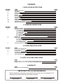
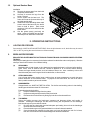
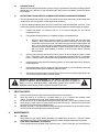
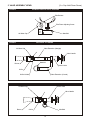
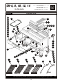
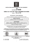
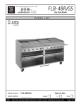
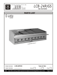
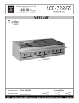
INSTALLATION AND OPERATING INSTRUCTIONS
Dante
SERIES
GAS CHAR BROILERS
Models: XX & CH
INTENDED FOR OTHER THAN HOUSEHOLD USE
RETAIN THIS MANUAL FOR FUTURE REFERENCE
BROILER MUST BE KEPT CLEAR OF COMBUSTIBLES AT ALL TIMES
IMPORTANT INSTRUCTIONS
After the gas supply has been connected to your unit, it is extremely important to check piping for possible
leaks. To do this, use soap and water solution or solutions which are expressly made for this purpose. DO
NOT USE matches, candles, flames, or other sources of ignition since these methods are extremely
dangerous.
CAP
MIXER
CAPAIR
MIXER
EXTENSION(CURVED)MANIFOLDAIR
SERIESVALVE
CHE
VIEW
SIDE
08-04-99FIG.3
REV.
1008-30
#
DGW.
576-0605ILLUSTRATION
(914)
Fax:
576-0200
:(914)
10801Tel
NY
Rochelle,
New
Street,
Pine
Co.30
Oven
Pride
CAPABakers
MIXER
BURNERAIR
SENSORPILOT
BURNERFLAME
SENSORPILOT
CAPAFLAME
MIXER
VIEWSAIR
ASSEMBLY
VALVE
AND
HANDLEMANIFOLD
HANDLEVALVE
SCREWVALVE
HOLD-DOWN
CAP
MIXER
AIR
VIEWA-
FRONT
SERIES
CHE
VIEWFIG.2
FRONT
SERIES
XXE
SERIESFIG.1
XXE
VIEW
SIDE
EXTENSION(STRAIGHT)FIG.4
VALVEVALVE
HOLDERBURNER
HOLDERBURNERORIFICEORIFICE
VALVEMANIFOLDBURNERORIFICEORIFICE
MANIFOLDMANIFOLDAABURNER
Post in a prominent location instructions to be followed in the event you smell gas. Obtain these instructions
from your local gas supplier.
!
FOR YOUR SAFETY
!
Do not store or use gasoline or other flammable vapors
and liquids in the vicinity of this or any other appliance.
WARNING
!
Improper installation, adjustment, alteration, service or maintenance can cause
property damage, injury or death. Read the Installation, Operating and
Maintenance Instructions thoroughly before installing or servicing this equipment.
!
This equipment has been engineered to provide you with year round dependable service when used
according to the instructions in this manual and standard commercial kitchen practices.
CERTIFIED
R
P/N U6023A 9/08
BAKERS PRIDE OVEN CO., INC.
30 Pine Street
New Rochelle, NY 10801
(914) 576-0200 Phone
(914) 576-0605 Fax
(800) 431-2745 US & Canada
www.bakerspride.com Web Address
[email protected] e-mail
1
CONTENTS
I. INSTALLATION INSTRUCTIONS
SECTION
1
2
3
4
5
6
7
8
9
10
11
12
ITEM
General Description
Installation
Clearances
Gas Connection
Burners
Radiants
Top Grates
Lighting
Griddle Plates
Additional Installation Requirements
Installation with Casters
Optional Smoker Boxes
PAGE
3
3
3
3
4
4
5
5
5
5
5
6
II. OPERATING INSTRUCTIONS
SECTION
1
2
3
4
5
ITEM
Lighting Procedure
Broiling Procedure
(a) Seasoning
(b) Steaks and Chops
(c) Hamburgers
(d) Thickness
(e) Cooking Tools
(f) Operational Guidelines for Char Broiler Natural Smoke Essence
Helpful Hints
Maintenance
(a) Service
(b) Care and Cleaning of Top Grates
(c) Grease Collection
(d) Cleaning Tools
Average Production Guide
PAGE
6
6
6
6
6
6
7
7
7
7
7
7
8
8
8
III. TROUBLESHOOTING GUIDE
SECTION
1
2
3
4
5
ITEM
Burner Flame Adjustment
Pilot Flame Adjustment
Lack of Heat
One Burner Fails to Light
Troubleshooting Chart
Valve Assembly Views
PAGE
8
8
8
9
9
10
IV. PARTS LISTS & EXPLODED VIEWS
ITEM
Models: XX-4, -6, -8, -10 & 12 Parts Lists & Exploded Views
Models: CH-6, -8, -10, -12 & 14 Parts List & Exploded View
PAGE
11
14
V. WARRANTY
ITEM
Bakers Pride Limited Warranty
PAGE
16
IMPORTANT FOR FUTURE REFERENCE
Please complete this information and retain this manual for the life of the equipment. For
Warranty Service and/or Parts, this information is required.
Model Number
Serial Number
2
Date Purchased
I. INSTALLATION INSTRUCTIONS
1.
GENERAL:
The instructions in this manual apply to all XX series and CH series Broilers.
The XX series may include the following options:
!
2.
INSTALLATION:
(a)
(b)
(c)
3.
Ceramic briquettes designated by a GS Suffix on the model number.
In USA, INSTALLATION of this broiler must conform with the latest edition of the
National Fuel Gas Code, ANSI Z223.1 and/or local codes.
In CANADA, INSTALLATION must conform with the latest edition of the National Gas
Installation Code, CAN/CGA-B149.1 or the Propane Installation Code, CAN/CGA-B149.2, as
applicable and/or local codes.
In MASSACHUSETTS, All gas products must be installed by a “Massachusetts” licensed
plumber or gas fitter. Ventilation hoods must be installed in accordance with NFPA-96,
current edition, with interlocks as described in that standard.
ACCEPTABLE CLEARANCES:
Due to intense heat generated by radiation, these broilers should be installed in non-combustible locations
only including above the grate level.
Right Side
Left Side
Back
4.
MINIMUM CLEARANCE FROM NON-COMBUSTIBLE CONSTRUCTION
Series XX
Series CH
0 inches
0 inches
0 inches
0 inches
0 inches
0 inches
GAS CONNECTION:
The gas pressure regulator supplied must be installed at the gas inlet of each broiler. Each regulator is
adjusted to yield a manifold pressure of 5 in. water column for natural gas or 10 in. water column for propane
gas. No pressure regulator is required for propane gas in Canada.
RECOMMENDED MINIMUM GAS SUPPLY LINES ARE LISTED BELOW
All XX Models
CH-4 thru CH-8
CH-10 thru CH-16
3/4”
1”
1 1/2”
For units using propane gas, supply lines less than ½” inside diameter should not be used, even for a small
unit.
On the XX and CH series, the gas connection is located on the right rear of the unit.
BE SURE TO CAP WHICHEVER SIDE IS NOT CONNECTED.
NOTE: A shut-off valve in a readily accessible location must be mounted on the gas supply line before the unit.
When making gas pipe connections, pipe joint compound resistant to the action of liquefied petroleum gases
should be used.
3
The broiler and its individual shutoff valve must be disconnected from the gas supply piping system during any
pressure testing of that system at test pressures in excess of ½ psig (3.45 kPa).
The broiler must be isolated from the gas supply piping system by closing its individual manual shutoff valve
during any pressure testing of the gas supply piping system at test pressures equal to or less than ½ psig (3.45
kPa).
5.
BURNERS:
Check to see that AIR MIXER CAPS on the front of all burners are tightened and adjusted, allowing half the
opening to show. Install the burners and deflector shields first following the steps below.
(a)
(B)
(c)
6.
Install all burners with deflector shield assemblies attached.
Place the front of the burner into the valve assembly by fitting the center hole of the mixer cap
over the brass orifice.
Drop the rear end of the burner over the burner support pin on the back of the unit.
RADIANTS:
Mount the “V” shaped radiants over the burners with each end mounted on special supports on the front and
rear of the chamber. A radiant should be mounted over each burner assembly.
GS Ceramic Briquettes Option:
The radiants supplied for the GS option are flattened to allow for the installation of an expanded metal grate.
The grate is installed directly on top of the flattened radiant burner shield. Ceramic briquettes are installed on
the grate as shown:
FIGURE 1
Typical Ceramic Briquette Installation
4
7.
TOP GRATES:
Place a grate over each of the radiants. For normal operation, the pointed side of the grate is facing up. For
use with foods that require extra support, the flat side may be used.
On XX Models, grates can be placed on three levels; two positions are built into the rear of the unit; the third
position requires a special adapter. On CH models, three positions are already built into the rear of the unit.
8.
LIGHTING:
Each burner on the base char broiler has a standing pilot burner that must be lit before the burners can be lit.
To light the pilot burners:
(a)
Turn all broiler valves to the off position.
(b)
Remove each top grate and radiant.
(c)
Open main gas SHUT-OFF valve (supplied by customer).
(d)
Allow air to bleed from the gas line through the pilot burners.
(e)
Light the pilot burners using a lit taper.
(f)
Turn the burner control valves “ON” to light the burners.
(g)
If any burner fails to light, turn the burner valves to “OFF”, wait five minutes and repeat the above
procedure.
(h)
After all burners have been ignited properly, turn each burner valve “OFF” and allow the unit to cool.
NOTE: Make sure that the pilot burners stay lit.
(i)
Replace radiants and top grates.
(j)
Each burner may now be adjusted to the desired flame size by turning the individual burner valve
handle.
(k)
To shut down the unit, turn all valves “OFF”
Wait five minutes before attempting to re-light.
NOTE: The pilot burners will stay lit until the gas supply to the unit is turned “OFF”.
9.
GRIDDLE PLATE:
Griddle plates should not cover more than 50% of the BROILING area. Each Griddle Plate fits on top of two grates
(one 4 1/2” and one 6”). It is not necessary to remove the top grates and radiants before installing the griddle plate.
10.
ADDITIONAL INSTALLATION INSTRUCTIONS
(a)
(b)
(c)
(d)
11.
Keep the area around the broiler free and clear of combustible materials.
The provision of an adequate air supply to your broiler is essential. Provide for sufficient outside
air to enter the broiling area and assure that this airflow is not obstructed.
Air enters the burner area from the front and bottom of your broiler. Assure that these areas are kept
open and unobstructed.
Servicing is accomplished through the front and top of the broiler. Assure that these areas are kept
unobstructed for proper servicing and operation.
INSTALLATION WITH CASTERS
(a)
(b)
(c)
(d)
Install the casters with the wheel brakes on the front of the appliance.
Installation should be made with a connector that complies with the latest edition of the Standard for
Connectors for Movable Gas Appliances, ANSI Z21.69 in the USA (CAN/CGA-6.16 in Canada), and a
quick disconnect device that complies with the latest edition of the Standard for Quick Disconnect
Devices for use with gas fuel, ANSI Z21.41 in USA (CAN 1-6.7 in Canada) and adequate means must
be provided to limit the movement of the appliance without depending upon the connector and any
quick disconnect device or its associated piping to limit the appliance movement.
The restraint should be attached to the legs on which the casters are mounted.
If disconnection of the restraint is necessary, the restraint should be reconnected after the appliance
has been returned to its originally installed position.
5
12.
Optional Smoker Base
Installation
(a)
Remove the grease pans from their rails
completely and set aside.
(b)
Unscrew to remove the legs from the
broiler. Discard.
(c)
Set the broiler into the base unit. The
frame will fit into the lip around the top of
each side and the back.
(d)
Install the #10 self-threading sheet metal
screws around the base into the broiler
frame to hold in place. Each screw
requires a 5/32 hole to be drilled into the
broiler frame.
(e)
Get the grease pan(s) previously set
aside. Insert a log holder into each pan.
Slide the pan into the bottom of the base.
II. OPERATING INSTRUCTIONS
1.
LIGHTING PROCEDURE:
See section 8 of INSTALLATION INSTRUCTIONS. Once the pilot burners are lit, the broiler may be turned
“ON” or “OFF” by turning the control valves on or off as necessary.
2.
BROILING PROCEDURE:
BROILER TOP GRATES MUST BE HOT ENOUGH TO MAKE BLACK CHAR-MARKS WHEN STARTING
TO BROIL.
Adequate pre-heating time is necessary for the food to release from the broiler and to cook properly. Allow the
unit to pre-heat for 45 minutes to 1 hour before broiling.
(a)
SEASONING:
Marinades with oil and vinegar or wine bases are best applied at least 1 to 2 hours before broiling.
Spice mixes, such as flavored salt etc., should be applied 10 to 30 minutes before broiling.
Tomato and sugar based products, such as barbecue sauces etc., have a tendency to burn and
should be used prior to removing the food from the broiler, or after removal.
(b)
STEAK AND CHOPS:
Cuts of meat with bones require longer cooking times at lower temperatures to reach the same
internal doneness as cuts without bones. To prepare a well-done steak, trim the fat to reduce
flare-up and the tendency to burn the outside.
(c)
HAMBURGERS:
Chopped steak, etc. MUST NOT BE TOO LEAN. For fat flare and smoking action in char-broiling,
hamburgers should have about 25% fat content.
Fat rendered out during broiling:
(1)
Helps to release the burger from the grates.
(2)
Helps the searing action that seals meat juices inside.
(3)
Enhances the char-broil flavor by flaring-up in the form of smoke and flame.
(d)
THICKNESS:
During the broiling process, the hamburger contracts and becomes thicker and smaller in
diameter. Pressing the hamburger out thin before broiling will compensate for the shrinkage.
Broil a hamburger as you would broil a steak.
(1)
Be sure that the char-broiler has had adequate pre-heating time so that the hamburger
does not stick to the broiler grate.
(2)
Place the hamburger on the grate and allow it to cook until release is attained.
(3)
Once the hamburger releases from the grate, turn it over and allow it to cook for 1 minute,
then turn once a minute until the desired degree of doneness is attained.
6
(e)
COOKING TOOLS:
Bakers Pride has designed a number of tools to help you operate more efficiently including a special
spatula that is very effective for fish and hamburgers. Other tools are available. Contact the factory
for full details
(f)
OPERATIONAL GUIDELINES FOR CHAR BROILER NATURAL WOOD SMOKE ESSENCE
Wood Smoke assist char broiling is more of an art than a science due to the many variables that affect
wood ignition, rate of combustion, as well as personal preference.
In order to obtain the optimal results and flavor transfer the wood should smolder, not flame. Place
wood in the log holders and follow the procedures recommended below and then adjust as required:
1)
Preheat char broiler on maximum heat for ½ hour before adjusting for your various
temperature zones.
2)
Fill log holders to approximately ¾ of capacity using dry or presoaked wood.
a)
!
3.
3)
As the wood incinerates and begins to turn to ash, it will lose its ability to impart a smoke
flavor. Periodically check the condition of the wood and replenish before it is completely
burned. This will ensure uninterrupted smoking capabilities throughout your service period.
4)
If the wood flares up because of the dripping grease or oil, spray water generously, directly on
the burning wood.
5)
If the wood tends to over flare, either pre-soak wood in water, or use a combination of dry and
pre-soaked wood as required to balance ignition and flare.
6)
The amount of wood needed to complete the meal service will vary greatly depending on the
size of the wood pieces and the moisture content.
IMPORTANT SAFETY INFORMATION: AT THE END OF THE MEAL SERVICE, IF
THERE IS UNSPENT WOOD REMAINING IN THE LOG HOLDERS, BE SURE TO
EMPTY IT INTO A SEALABLE METAL CONTAINER, DOUSE WITH WATER, STIR
EMBERS, DOUSE AGAIN, THEN COVER WITH AN AIRTIGHT LID!!!
!
HELPFUL HINTS:
(a)
(b)
(c)
(d)
(e)
4.
When the char broiler's burners are set to maximum flame, the wood will begin
smoking. While several factors will affect the rate of combustion of the wood, such
as moisture content of the wood, size of the wood, type of wood, elevation above sea
level, you can generally expect smoldering to begin in approximately 35-50 minutes.
However, the flavor transfer or ability to impart a smoky flavor into your food product
will occur sooner, approximately 15 minutes, or as soon as the aroma of burning
wood is evident.
Do not press the juice out of the meat because that will cause a dry product.
Allow the meat to sit covered on a heated platter for 2 to 5 minutes after broiling before
cutting. This will allow the juices to “settle” and the product will be more moist.
Do not use forks or other sharp objects which poke holes in the meat. Do not cut the meat as it cooks
Thick pieces of meat require a longer broiling time with less flare-up. Reduce flare-up trimming
excess fat for a longer broil time without burning.
Keep the unit clean. Food caught between the grates will not allow hot air to rise around the product.
This will result in uneven heating and increase cook time.
MAINTENANCE:
(a)
(b)
SERVICE:
Shut off the main gas supply before attempting any maintenance on the unit. If required, contact
your Dealer, the Factory, or a local Service Company to obtain qualified maintenance and repairs.
CARE AND CLEANING OF TOP GRATES:
The top grates should be cleaned using a stiff wire brush. If this is done daily, the accumulation of
7
food and fat caught in the grates and work necessary to keep them clean will be reduced.
Periodically, they should be turned over and brushed and then put back. In the event that an extra
amount of fat is accumulated on the top, due to use of low heat, we recommend turning up the flame
of this section for about an hour, which will burn off much of the fat and residue and the brushing
operation will be easier. Under no circumstances should the grates be placed in a dishwasher.
Soap, water, or any detergents should never be used on the cast iron grates.
(c)
GREASE COLLECTION:
Your char-broiler is designed to bring grease into the front channel which in turn drains the grease into
the grease collection pan in the lower section of the broiler. The pan in the lower section should be
cleaned daily or more often if necessary. The channel should be cleaned periodically with a stiff
brush or scraper.
(d)
CLEANING TOOLS:
Several models of specially designed top grate brushes and grease drain scrapers are available from
Bakers Pride. Contact Bakers Pride for more information.
5. AVERAGE PRODUCTION GUIDE:
Estimated Hourly Production
MODEL NUMBER
CH-4
XX-4
CH-6
XX-6
CH-8
XX-8
CH-10
XX-10
CH-12
XX-12
CH-14
CH-16
BROILING AREA
21” x 24”
31 1/2” x 24
42” x 24”
52 1/2” x 24”
63” x 24”
73 1/2” x 24”
84” x 24”
3 OZ. BURGERS
600
900
1200
1500
1800
2100
2400
12 OZ. STEAKS
120
180
240
300
360
420
480
The table above gives estimated hourly production as a guide only. Actual production may vary depending on required
doneness, thickness and weight of product.
III. TROUBLE SHOOTING GUIDE
CAUTION: Take extreme care to assure that, if a valve is opened, a flame is present. If a valve is left open
without a flame, turn the valve off and wait at least five minutes before attempting to (re)light. Service should
be performed only by a qualified gas technician.
1.
BURNER FLAME ADJUSTMENT:
(a)
(b)
2.
The burner flame should be as blue as possible. However, there will be traces of orange and/or yellow
from particles in the air burning in the flame. Slight yellow tips at the flame ends are acceptable.
If the flame appears yellow, loosen the air-mixer cap hold down screw “A” (see figs. 2 and 3). Rotate
the air mixer cap counter-clockwise to allow more air into the burner, until the flame turns blue.
Tighten the screw.
PILOT FLAME ADJUSTMENT:
The pilot flame can be adjusted by turning the appropriate adjusting screw using a screwdriver or a 3/16
wrench (see fig. 2), counter-clockwise to increase, clockwise to decrease and close. The pliot flame should be
about ½ inch long.
3.
LACK OF HEAT:
Check to see if the pilot flames are on. If they are on but the burners do not light, or the burner flames look
weak, then there is a possibility of a gas pressure loss to the broiler.
(a)
Check that the unit's main valve is fully open. Normally in the open position, the valve handle will be
parallel to the piping. The valve should be located somewhere on the gas line feeding the charbroiler. If the handle is NOT parallel to the piping, the unit is not getting the gas supply required to
operate properly. Turn the valve handle parallel to the gas supply line.
8
(B)
If there is a problem with the gas supply, it may be checked fairly easily. Turn off half of the burners
or turn off all other gas appliances and see if the broiler flames increase. If there is an increase in the
flame height then there is a problem with the gas supply. A problem with the gas supply requires
immediate attention. IMMEDIATELY close all the burner valves (turn to the off position), including
the char-broiler's main valve. Contact a qualified service agency or the public gas company.
The following should be checked:
1.
The building's main pressure regulator.
2.
The size of the broiler's gas supply line (if it is a new installation).
3.
The broiler's pressure regulator.
4.
The orifice size of each burner.
4.
ONE BURNER FAILS TO LIGHT:
NOTE: Always make sure that grates, radiants and burners are cold before handling.
(a)
Check to see that the on/off valve to that burner is on.
(b)
Check to see if the pilot flame is lit. Each burner has its own pilot, which is located on the manifold
along the front of the char-broiler (see fig. 2).
If the pilot is not lit, attempt to light it using a long taper. If it fails to light, turn off all the burners,
allow to cool and then remove the top grate and the radiant over the burner. With a thin wire or pin,
check that the hole is clear at the top of the pilot tube. Attempt to relight using a taper.
(c)
If the pilot burner is lit, close all the burner valves, allow to cool and then remove the top grate and
the radiant over the burner, and check that the pilot flame is located over the first few holes in the
burner. The pilot tube can be bent slightly to reposition the flame.
(d)
If the pilot is lit, positioned correctly, and has a proper flame, close all the burner valves , allow to
cool and then remove the top grate and radiant over the burner.
Remove the burner by lifting the rear of the burner off the support pin, slide it towards the rear of the
broiler, enough to clear the burner orifice (fig. 3 or 4).
Using a thin wire or pin, check to see that the orifice is clear, taking care not to enlarge the hole.
Replace the burner, radiant and grate and attempt to light it again.
If the burner will not light, the burner valve could be defective. Contact your dealer, the factory or a
local service company.
For additional information contact: Bakers Pride Oven Co., Inc. (914) 576-0200.
TROUBLESHOOTING CHART
PROBLEM
PROBABLE CAUSE
SOLUTION
Burners & pilots will
not turn on
Burners produce
excessive carbon
deposits
Turn on main gas supply.
Excessive flare-up
Broiler doesn't seem
hot enough
Main gas supply to broiler is not
turned on.
Incorrect gas type.
Incorrect gas supply pressure.
Incorrect orifices.
Primary air not adjusted properly.
Pilot flame adjusted incorrectly.
Draft condition.
Improper ventilation system.
Overload of fatty meat.
Orifices may be dirty/clogged.
Low gas pressure.
Grates &/or radiants
&/or burners &/or gas
valves warp
Top grates may be dirty/clogged.
If the ventilation is too strong it will
suck heat from the cooking/broiling
surface.
Usually improper cleaning methods
ie; users cover grate top w/sheet pans
& crank up heat to burn-off debris
Pilot will not remain lit
9
Supply correct type gas.
Call local gas supplier.
Call Bakers Pride authorized service center.
Adjust air shutter.
Adjust pilot flame.
Remove draft.
Call an HVAC specialist.
Add water to grease pan.
When unit cools, check & clean orifices.
Increase gas pressure to 5" W.C. (Nat) or
10" W.C. (L.P.)
When unit cools, check & clean top grates.
Call an HVAC specialist.
Do not "Burn-Off" top grates. This causes the
firebox area to overheat excessively. *Never
Cover top grates.
5. VALVE ASSEMBLY VIEWS:
FIGURE 2
(A = Cap Hold-Down Screw)
AIR MIXER CAP AND PILOT BURNERS
Pilot Burners
A
Pilot Flame Adjusting Screw
Air Mixer Cap
Manifold
FIGURE 3
SIDE VIEW - CH SERIES
Air Mixer Cap
Valve Extension (Straight)
A
Valve Handle
Manifold
Burner
Burner Valve
Orifice
Orifice Holder
FIGURE 4
Valve Extension (Curved)
SIDE VIEW - XX SERIES
Burner Valve
Air Mixer Cap
Valve Handle
A
Burner
Manifold
Orifice
10
IV. PARTS LISTS & EXPLODED VIEWS
30 Pine Street • New Rochelle • New York • 10801
XX-4, 6, 8, 10, 12
914 / 576 - 0200
914 / 576 - 0605 fax
1 - 800 - 431 - 2745 US & Canada
www.bakerspride.com web address
Gas Char Broiler
BAKERS
PRIDE
Burner / Accessories
Figure B
20
21
28
28
11
12
27
27
30
12
13
15
16
16
17
13
14
25
26
18
19
24
25
14
15
17
18
23
24
9
10
29
29
76
8
9
87
11
5
Item
Part #
1
2
3
4
5
6
7
8
9
10
11
12
13
14
15
R1017X
R1018X
R1019X
R1020X
R1133X
N3068P
N5217A
R3020X
R3042X
R3032X
S1416X
L5019X
L5013X
H1044X
Q4008X
4
4
3
2
21
22
1
Description
22
23
65
Item
Part #
16
17
18
19
20
21
22
23
24
25
26
27
28
29
30
L5027V
L5014V
R3022X
H1008X
T1007A
T1155T
M1009X
M1008X
R3043X
R3044X
R3023X
T5041T
T5104V
G5221U
G1290U
Manifold Assy (XX-4)
Manifold Assy (XX-6)
Manifold Assy (XX-8)
Manifold Assy (XX-10)
Manifold Assy (XX-12)
Pressure Tap Nozzle Assy
Gas Inlet Pipe (XX Series)
Valve, Pilot-Dual
Pilot Tubing, 7 3/8" (XX Series)
Valve, Burner (LML) w.o./Knob
Knob, Gas Valve, On/Off (XX Series)
Burner Assy Complete, Tube 24" (XX)
Burner Only, Tube 24" (XX)
Grease Guard Only (Tube Burner)
Cotter Pin, 1/8" x 2"
Conversion Kit (LP to Nat)
R3043X
M1008X
Page 4 of 4
Description
Burner Assy Complete, C.I. 24" (XX) O/S
Burner Only, C.I. 24" w/ Mixer Cap (XX) O/S
Air Mixer Cap w/Screw (C.I. Burner only)
Grease Guard Only (C.I. Burner)
Radiant Cast Iron (23") Optional (Shown)
Radiant S/S (23") Standard
Pressure Regulator, 3/4", 10" WC
Pressure Regulator, 3/4", 5" WC
Orifice Hood #47, Nat (XX)
Orifice Hood #55, LP (XX)
Orifice Hood, Blank
Grate Lifter (Cast Iron), 3' x 20"
Twin Head Grate Brush
Grate Lifter (Roll-A-Grate)
Bottom Grate Burner Shield (Glo-Stone Only)
Conversion Kit (Nat to LP)
R3044X
Hood Orifice # 47, Nat. (XX-4 uses 4)
(XX-6 uses 6) (XX-8 uses 8) (XX-10 uses 10)
(XX-12 uses 12)
Pressure Regulator, 3/4", 5" WC (Qty. 1)
M1009X
Hood Orifice #55, L.P. (XX-4 uses 4)
(XX-6 uses 6) (XX-8 uses 8) (XX-10 uses 10)
(XX-12 uses 12)
Pressure Regulator, 3/4", 10" WC (Qty. 1)
Note: When ordering, ALWAYS specify Part #, Model #, Serial #, Voltage/Phase & type of Gas.
11
2/05
30 Pine Street • New Rochelle • New York • 10801
XX-4, 6, 8, 10, 12
914 / 576 - 0200
914 / 576 - 0605 fax
1 - 800 - 431 - 2745 US & Canada
www.bakerspride.com web address
Gas Char Broiler
BAKERS
PRIDE
Exterior / Grates
Figure A
14
f
e
Of Plat
t
f
Li dle
d
i
Gr
e
lat
P
e
dl
d
i
Gr
16
15
22
11
5
24
7
8
7
21
2
4
3
23
6
10
9
12
Meat Grate
19
Page 2 of 4
Cast Iron Grate
17
Roll-A-Grate
18
13
Fish Grate
20
Note: When ordering, ALWAYS specify Part #, Model #, Serial #, Voltage/Phase & type of Gas.
12
2/05
XX-4, 6, 8, 10, 12
30 Pine Street • New Rochelle • New York • 10801
BAKERS
PRIDE
Item
Part #
914 / 576 - 0200
914 / 576 - 0605 fax
1 - 800 - 431 - 2745 US & Canada
www.bakerspride.com web address
Description
Gas Char Broiler
Item
Part #
Description
Exterior / Grates
G1013X
Control Panel (XX-4)
G1014X
Control Panel (XX-6)
G1082X Splash Guard, S/S (XX-6) Optional
G1015X
Control Panel (XX-8)
G1083X Splash Guard, S/S (XX-8) Optional
G1016X
Control Panel (XX-10)
G1084X Splash Guard, S/S (XX-10) Optional
G1249K
Control Panel (XX-12)
G1237U Splash Guard, S/S (XX-12) Optional
G1007X
Top Front Trim (XX-4)
T3033T
Grease Pan (XX-4 & 12) 20 3/8", 1 used
G1008X
Top Front Trim (XX-6)
T3034T
Grease Pan (XX-6 & XX-10) 30 7/8", 1 used
G1009X
Top Front Trim (XX-8)
T3035T
Grease Pan (XX-8) 19 5/8", 2 used or (XX-12) 1 used
G1010X
Top Front Trim (XX-10)
T3036T
Grease Pan (XX-10) 19 1/2", 1 used
G1248K
Top Front Trim (XX-12)
G1122K
Outer Back (XX-4)
S1394X Leg, 4" Adjustable, Cylindrical 2" Dia. (Set/4)
G1123K
Outer Back (XX-6)
G1495A Leg Adaptor (Not Shown)
G1124K
Outer Back (XX-8)
G1125K
Outer Back (XX-10)
14
T1241U Lift-Off Griddle 10 1/2"
G1232K
Outer Back (XX-12)
15
T1251T
In-Line Griddle 10 1/2"
G1051K
Front Brace (XX-4)
16
T1020T
Griddle Plate 16"
G1052K
Front Brace (XX-6)
17
T1216A
Grate, Top, Flat Cast Iron (4 1/2")
G1053K
Front Brace (XX-8)
T1212A
Grate, Top, Flat Cast Iron (6")
G1054K
Front Brace (XX-10)
T1199U
Roll-A-Grate (4 1/2")
G1245K
Front Brace (XX-12)
T1198U
Roll-A-Grate (6")
G1021X
1st/2nd Level Assy (XX-4)
G1022X
1st/2nd Level Assy (XX-6)
G1023X
1st/2nd Level Assy (XX-8)
T1230T
Grate, Fish (4 1/2")
G1024X
1st/2nd Level Assy (XX-10)
T1229T
Grate, Fish (6")
G1247K
1st/2nd Level Assy (XX-12)
T1166T
Grate, Fish (10 1/2")
G1070X
Work Deck, S/S (XX-4) Optional
21
T1183T
Grate, Fajita, Bottom
G1078X
Work Deck, S/S (XX-6) Optional
22
T1185S
Grate, Fajita, Top
G1079X
Work Deck, S/S (XX-8) Optional
23
T1243U Long Bottom Grate 31 9/16 (Glo-Stone Option Only)
G1080X
Work Deck, S/S (XX-10) Optional
G1296K
Work Deck, S/S (XX-12) Optional
G1011X
Top Side Trim, SS, Left
G1012X
Top Side Trim, SS, Right
XX-6: (1) T1243U, (3) T1250A
8
G1126X
Outer Side, Left (XX)
XX-8: (2) T1242U, (4) T1250A
9
G1127K
Outer Side, Right (XX)
XX-10: (1) T1242U, (1) T1243U, (5) T1250A
10
U1044X
Name Plate, 8", Bakers Pride
XX-12: (2) T1243U, (6) T1250A
1
2
3
4
5
6
7
2/05
11
12
13
G1081X Splash Guard, S/S (XX-4) Optional
S1394Y Leg, 4" Adjustable, Cylindrical 2" Dia. (Each)
(Needed for old style tapered, hex top legs only)
18
19
T1217U Grate, Meat (4 1/2")
T1210U Grate, Meat (6")
20
T1242U Short Bottom Grate 21 1/16 (Glo-Stone Option Only)
24
T1250A
Briquettes, Ceramic 9.5 lb Bag (Glo-Stone Option Only)
NOTE:
XX-4: (1) T1242U, (2) T1250A
Note: When ordering, ALWAYS specify Part #, Model #, Serial #, Voltage/Phase & type of Gas.
13
Page 3 of 4
CH-6, 8, 10, 12, 14
30 Pine Street • New Rochelle • New York • 10801
914 / 576 - 0200
914 / 576 - 0605 fax
1 - 800 - 431 - 2745 US & Canada
www.bakerspride.com web address
Gas Char Broiler
BAKERS
PRIDE
Exploded View
Figure A
56
11
55
1
54
12
13
53
14 15
52
16 17
29
51
20
18
28
26
19
21
50
27
22
49
25
48
47
36
23
24
30
35
36
31
69
60
34
32
68
33
57
38
42
44
46
2
Page 2 of 4
39
70
62
61
43
63
59
58
45
64
10
5
3
41
40
37
9
7
4
65
66
8
6
72
71
Note: When ordering, ALWAYS specify Part #, Model #, Serial #, Voltage/Phase & type of Gas.
14
67
8/03
30 Pine Street • New Rochelle • New York • 10801
914 / 576 - 0200
914 / 576 - 0605 fax
1 - 800 - 431 - 2745 US & Canada
www.bakerspride.com web address
BAKERS
PRIDE
Item
Part #
Description
CH-6, 8, 10, 12, 14
Gas Char Broiler
Item
Part #
Description
Parts List (See Figure A)
1
2
3
4
5
6
7
8
9
10
N/S
N/S
11
12
13
14
15
16
17
18
19
20
21
22
23
24
25
26
27
28
29
30
31
32
33
34
35
36
37
38
39
T1006A
T1217U
T1210U
T1216A
T1212A
T1199U
T1198U
T1230T
T1229T
T1166T
T1228T
T1227T
T1020T
T1007A
T1155T
L5019X
L5013X
L5027V
L5014V
R3022X
H1044K
H1008K
Q4008A
R3032X
S1094X
N1006X
N1005X
R3025X
R3028X
R3031X
R3026X
M1008X
M1009X
M1066X
M1067X
R3021X
R3020X
R3034X
T3015T
T3016T
T3018T
Top Grate 5 1/4' Wide
Grate, Meat (4 1/2")
Grate, Meat (6")
Grate, Top, Flat Cast Iron (4 1/2")
Grate, Top, Flat Cast Iron (6")
Roll-A-Grate (4 1/2")
Roll-A-Grate (6")
Grate, Fish (4 1/2")
Grate, Fish (6")
Grate, Fish (10 1/2")
Grate, Tango (6")
Grate, Tango (9")
Griddle Plate (Optional)
Radiant Deflector (Cast Iron)
Radiant Deflector (Stainless Steel)
Tube Burner Assy w/Grease Guard
Tube Burner w/Air Mixer Cap
Cast Iron Burner w/Grease Guard O/S
Cast Iron Burner w/Air Mixer Cap O/S
Air Mixer Cap w/Screw (for O/S CI Burner)
Burner Grease Guard
Burner Grease Guard (for O/S CI Burner)
Cotter Pin
Gas Valve (without knob)
Gas Valve Knob
Curved Valve Extension
3 5/8" Straight Valve Extension
Orifice Holder (Only)
Orifice Spud #49 Drill (.073") Nat.
Orifice Spud #56 Drill (.0465") LP
Orifice Spud - Special Drill Size (Specify)
Pressure Regulator 3/4" Nat 5"WC (CH 6, 8)
Pressure Regulator 3/4" LP 10"WC (CH 6, 8)
Pressure Regulator 1" Nat 5"WC (CH 10, 12, 14)
Pressure Regulator 1" LP 10"WC (CH 10, 12, 14)
Adjustable Pilot Valve (Single)
Adjustable Pilot Valve (Double)
S/S Pilot Tube 6" w/nut & ferrule
Grease Pan (CH-4)
Grease Pan (CH-6)
Grease Pan (CH-8)
40
41
42
43
44
45
46
47
48
49
50
51
52
53
54
55
56
57
58
59
60
61
62
63
64
65
66
67
68
69
70
71
72
N/S
N/S
N/S
N/S
N/S
N/S
N/S
N/S
Conversion Kit (LP to Nat)
R3028X
Grease Pan, set/2 (CH-10)
Grease Pan, set/2 (CH-12)
Grease Pan, set/3 (CH-14)
Grease Pan, set/3 (CH-16)
Grease Pan, set/3 (CH-18)
Grease Pan, set/4 (CH-20)
Grease Pan, set/4 (CH-22)
S/S Heat Shield w/Handle (CH-4)
S/S Heat Shield w/Handle (CH-6)
S/S Heat Shield w/Handle (CH-8)
S/S Heat Shield w/Handle set/2 (CH-10)
S/S Heat Shield w/Handle set/2 (CH-12)
S/S Heat Shield w/Handle set/3 (CH-14)
S/S Heat Shield w/Handle set/3 (CH-16)
S/S Heat Shield w/Handle set/3 (CH-18)
S/S Heat Shield w/Handle set/4 (CH-20)
S/S Heat Shield w/Handle set/4 (CH-22)
Heat Shield Handle w/Hardware
4" Caster w/o Lock (each)
4" Caster w/Lock (each)
Front Leg Left w/caster 12" (each)
Front Leg Cen. & Right w/caster 12" (each)
Rear Leg w/caster 12" (each)
Leg 12" (each)
Legs w/Casters set/4 (12")
Legs w/Casters set/6 (12")
12" Legs set/6
12" Legs set/4
Grease Drawer w/Handle Left (All)
Grease Drawer w/Handle Right (CH14-22)
Grease Drawer Handle w/Screws
Grate Lifter (Roll-A-Grate)
Grate Lifter (Cast Iron) 3' x 20"
Richlite CH-6 (Optional)
Richlite CH-8 (Optional)
Richlite CH-10 (Optional)
Richlite CH-12 (Optional)
Richlite CH-14 (Optional)
Splash Sides (Set/2)
Griddle Plate 10 1/2" (In Line)
Griddle Plate 18" (In Line)
Conversion Kit (Nat to LP)
Orifice Spud #49 Drill (.073") Nat.
R3031X
(CH-6 uses 6, CH-8 uses 8, CH-10 uses 10,
Orifice Spud #56 Drill (.0465") LP
(CH-6 uses 6, CH-8 uses 8, CH-10 uses 10,
CH-12 uses 12, CH-14 uses 14)
CH-12 uses 12, CH-14 uses 14)
M1008X Pressure Regulator 3/4" Nat 5"WC (CH 6, 8)
M1066X Pressure Regulator 1" Nat 5"WC (CH 10, 12, 14)
8/03
T3120X
T3121X
T3122X
T3123X
T3124X
T3125X
T3126X
T3078V
T3079V
T3080V
T3081X
T3082X
T3083X
T3084X
T3085X
T3086X
T3087X
S1134X
S1022X
S1023X
S1090T
S1091T
S1089T
S1018T
S1115Y
S1116Y
S1017Y
S1018Y
T3045T
T3046T
S1016X
G5221U
T5041T
T1190A
T1189A
T1174A
T1122A
T1123A
H1530S
T1251T
T1252T
M1009X Pressure Regulator 3/4" LP 10"WC (CH 6, 8)
M1067X Pressure Regulator 1" LP 10"WC (CH 10, 12, 14)
Note: When ordering, ALWAYS specify Part #, Model #, Serial #, Voltage/Phase & type of Gas.
15
Page 3 of 4
V. BAKERS PRIDE LIMITED WARRANTY
30 Pine Street New Rochelle, New York 10801
914 / 576 - 0200 ♦ US & Canada: 1 - 800 - 431 - 2745 ♦ fax 914 / 576 - 0605
WHAT IS COVERED
This warranty covers defects in material and workmanship under normal use, and applies only to the original purchaser
providing that:
* The equipment has not been accidentally or intentionally damaged, altered or misused;
* The equipment is properly installed, adjusted, operated and maintained in accordance with National and local codes. and
in accordance with the installation instruction provided with the product;
* The serial number rating plate affixed to the equipment has not been defaced or removed.
WHO IS COVERED
This warranty is extended to the original purchaser and applies only to equipment purchased for use in the U.S.A.
COVERAGE PERIOD
Full size gas and electric deck ovens: Two (2) year limited parts and labor: Cyclone Convection Ovens: BCO Models: One (1)
Year limited parts and labor; GDCO Models: Two (2) Year limited parts and labor; CO II Models: Two (2) Year limited parts
and labor; (5) Year limited door warranty.
All Other Products: One (1) Year limited parts and labor.
Warranty period begins the date of dealer invoice to customer or ninety (90) days after shipment date from BAKERS PRIDE whichever comes first.
WARRANTY
COVERAGE
This warranty covers on-site labor, parts and reasonable travel time and travel expenses of the authorized service
representative up to (100) miles. round trip, and (2) hours travel time. The purchaser. however, shall be responsible for all
expenses related to travel, including time. mileage and shipping expenses on smaller counter models that may be carried into
a Factory Authorized Service Center, including the following models: PX-14. PX-16, PI8, and BK-I8.
EXCEPTIONS
All removable parts in BAKERS PRIDE Char-broilers, including but not limited to: Burners, Grates. Radiants, Stones and
Valves, are covered for a period of SIX MONTHS.
All Ceramic Baking Decks are covered for a period of THREE MONTHS. The installation of these replacement decks is the
responsibility of the purchaser.
The extended Cyclone door warranty years 3 through 5 is a parts only warranty and does not include labor, travel, milage or
any other charges.
EXCLUSIONS
* Failures caused by erratic voltages or gas supplies,
* Unauthorized repair by anyone other than a BAKERS PRIDE
Factory Authorized Service Center,
* Damage in shipment,
* Alteration, misuse or improper installation,
* Thermostats and safety valves with broken capillary tubes.
* Accessories - spatulas, forks. steak turners, grate lifters,
oven brushes, scrapers, peels. Etc.,
* Freight - other than normal UPS charges,
* Ordinary wear and tear.
* Negligence or acts of God,
* Thermostat calibrations after (30) days from equipment
installation date,
* Air and Gas adjustments,
* Light bulbs,
* Glass doors and door adjustments.
* Fuses,
* Char-broiler work decks and cutting boards,
* Tightening of conveyor chains,
* Adjustments to burner flames and cleaning of pilot burners,
* Tightening of screws or fasteners.
INSTALLATION
Leveling and installation of decks. as well as proper installation and check out of all new equipment - per appropriate
installation and use materials - is the responsibility of the dealer or installer, not the manufacturer.
REPLACEMENT
PARTS
BAKERS PRIDE genuine Factory OEM parts receive a (90) day materials warranty effective from the date of installation by a
BAKERS PRIDE Factory Authorized Service Center.
This Warranty is in lieu of all other warranties, expressed or implied, and all other obligations or liabilities on the manufacturers part. BAKERS PRIDE
shall in no event be liable for any special, indirect or consequential damages, or in any event for damages in excess of the purchase price of the unit. The
repair or replacement of proven defective parts shall constitute a fulfillment of all obligations under the terms of this warranty.
Form #U4177A 1/07
16