1
BOSCH
INSTALLATION
INSTRUCTION
MANUAL for
Bosch Electric Built-in Single & Double Oven
Models HBL 73oo/74oo/75oo/76ooand
Models HBN 74.o/75.o/76.o
BEFORE YOU BEGIN, READ THESE ][NSTRUCTI[ONS COMPLETELY
AND CAREFULLY
Save these instructions
for the local electrical inspector's
Please leave this manual with owner for future reference.
Please keep this manual
for future
use.
reference°
VEUILLEZ LIRE ATTENTIVEMENT CE MANUEL AVANTDE COMMENCER UINSTALLATION
2002 BSH Home Appliances
(. orp.
Technical
Data .....................................................................................................
HBL Models: Single Oven, Double Oven ..........................................................
HBN Models: Single Oven, Double Oven .........................................................
Undercounter
Installation
........................................................................................
Single Oven ........................................................................................................
Wall Installation
..................................................................................................
Single Oven ........................................................................................................
Double Oven .......................................................................................................
Electrical Supply ...............................................................................................
Wiring Requirements ..................................................................................
Connecting To 208 Volt Circuit ........................................................................
PB
4 - 5
4
5
6
6
7 - 8
7
8
9 - 10
9- 10
10
Electrical Connections
............................................................................................
3-Wire Branch Circuit ......................................................................................
4-Wire Branch Circuit ......................................................................................
11
11
11
Final Checklist
12
........................................................................................................
INTRODUCTION
POWER
PleasereadtheseinstructionsCOMPLETELY
AND CAREFULLY.Theywill saveyou time and
The oven must be supplied with the proper voltage and frequency. The oven is mamffactured to be
connected to a three=wire or four-wire, single phase,
240 Volt, 60 Hz AC electlical supply on a separate
circuit fused on both sides of the line. If a 208 Volt
eflbrt and help to ensure optimum oven pertbnnance.
Be sure to observe all WARNINGS.
These instaRation
instructions
are intended
use by a qua|iiied insta||er. In addition
instructions, the oven shall be installed:
.
In the United
States, in accordance
tional Electric Code/State
and/or local codes.
.
fur
to these
with the Na-
and Municipal
codes
In Canada, in accordance with Canadian Electric
Code C22. l-latest edition/Provincial
and Municipal codes and/or local codes.
These shall be carefully
Note:
folk)wed
at all times.
If installing your oven in Canada please
check to make sure that you have a model
with the UL Canadian
shown below:
listing
mark,
as
REQUIREMENTS
circuit must be used, see Com:,ecting lo 208 t'o/t
Circz:iL in this manual. A circuit breaker or timedelay fuse sized not to exceed the circuit rating of
the appliance specifed on the rating plate located
on the tiame behind the door of the oven is recommended.
The oven must be supplied
ONLY.
It is recommended
with copper
wires
that you have the electrical
wiring and hook-up of your oven performed by a
qualified electrician. After installation is compKte
have the electrician show you where the main dis=
connect is and which of the circuit breakers/fuses
are for the oven.
CHOOSING
OVEN
LOCATION
Carefully select the location where the oven will
be placed. The oven should be located for conve=
nient use in the kitchen, but away flom strong drafts.
The UL Canadian listing
circled UL symbol preceded
mark consists of the
by the letter "C," as
shown. This should appear on the oven's rating plate
along with the UL United States listing mark, which
is the circled UL symbol above Nit not preceded by
the letter "C."
TOOLS
YOU WILL
The following
new
STEPS
FOR
INSTALLATION
The %llowing pages provide the necessa U in%rmation for proper installation of the oven arranged
as follows:
NEED
tools are needed
Strong drafts may be caused by open doors or windows, or by heating and/or air conditioning vents or
fires. Make sure that electrical power can be provided to the location selected.
to install your
.
Technical
.
Installation
oven:
Data
Cutout Dimensions,
ances and Mounting
" Tape measure
and straightedge
.
Pencil
.
Phillips
.
Level
.
Wire cutters
.
1-inch hole saw
,
Hand or saber saw
or rifler
screwdriver
.
and wire stripper
Installation,
Required
Clear-
for:
>
Undercounter
>
Wall Installation,
Single Oven
>
Wall Installation,
Double Oven
Single Oven
Electrical Supply and Wiring Requirements,
Programming required if connecting to 208 Volt Circuit. Electrical Connections tbr 3-wire or 4-wire
Branch
.
instructions
Circuit.
Final Checklist
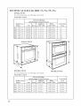
TECHNICAL
SINGLE
DATA for HBL 73o./74o./75o./76o.
OVEN
For cutout dimensk_ns
Preparing
see folk_wmg section titled:
Location
and Maximum
Single Oven
Models
Volts
Hertz
HBL 732A UC
240/208
HBL 735A UC
HBL 736A UC
Connected
Load
Watts
Convection
Amperes
@240V/208V
@240V/208V
60
15.4/17.2
3,600/3,500
No
240/208
60
15.4/17.2
3,600/3,500
No
240/208
60
15.4/17.2
3,600/3,500
No
HBL 742A UC
240/208
60
15.8/17.6
3,650/3,550
Yes
HBL 745A UC
240/208
60
15.8/17.6
3,650/3,550
Yes
HBL 746A UC
240/208
60
15.8/17.6
3,650/3,550
Yes
SINGLE
Oven
OVEN
m
--;F-
.r2)
_22
_o
.2r-/
DOUBLE
OVEN
DOUBLE
For cutout dimensions
Preparing
Location
see following
section titled:
Electrical Ratings
and Maximum
Connected
Double
Models
PB
Oven
OVEN
Load
Amperes
Watts
@240V/208V
@240V/208V
Convection
Oven
Volts
Hertz
HBL 752A UC
240/208
60
31.2/34.8
7,250/7,050
Yes/No
HBL 755A UC
240/208
60
31.2/34.8
7,250/7,050
Yes/No
HBL 756A UC
240/208
60
31.2/34.8
7,250/7,050
Yes/No
HBL 765A UC
240/208
60
31.6/35.2
7,300/7,100
Yes/Yes
(top/bottom)
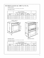
TECHNICAL
SINGLE
DATA for HBN 74o./75o./76o.
OVEN
For cutont dimem;ions
Preparing
see follnwing
section titled:
Location
Electrical
Ratings
and Maximum
Connected
Load
Watts
Convection
Oven
Amperes
@240V/208V
@240V/208V
60
15.8/17.6
3,650/3,550
Yes
240/208
60
15.8/17.6
3,650/3,550
Yes
240/208
60
15.8/17.6
3,650/3,550
Yes
Volts
Hertz
HBN 742A UC
240/208
HBN 745A UC
HBN 746A UC
SINGLE
OVEN
--i
--X-
E-
E-
4
jr-
V/
J
DOUBLE
OVEN
DOUBLE
For cutout dimensions
Preparing
Location
see fi_Howing section titled:
Electrical
Ratings
and Maximum
Connected
Double
Models
OVEN
Oven
Load
Convection
Amperes
Watts
@240V/208V
@240V/208V
60
31.2/34.8
7,250/7,050
Yes/No
240/208
60
31.2/34.8
7,250/7,050
Yes/No
HBN 756A UC
240/208
60
31.2/34.8
7,250/7,050
Yes/No
HBN 765A UC
240/208
60
31.6/35.2
7,300/7,100
Yes/Yes
Volts
Hertz
HBN 752A UC
240/208
HBN 755A UC
Oven
(top/bottom)
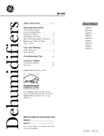
UNDERCOUNTER
INSTALLATION,
SINGLE
OVEN
I Ovenelectricalsupply:Locatejunctionbox
I
u:
Z
O
00
I
E
@
o
o
I in adjacent cabinet or betow bottom I
I
supportsurface.
I
I NBL Node,s: 28"openingwidth
I
I
I HBN Models: 25-3/8"openingwidth
O
I
I
C-0
Bottomsupportsurfacemustbesolid,level
and able to supportat least 150 Ibs.
I
I
1/4" rain.distancebetweenoven
door frameand adjacentdoorsor
drawerfronts.
Toespacearea
. HBLModels:29ol/4"widthofovendoorframe..
NBNModels:26o5/8"
widthofovendoorframe
NOTE: Decorative inserts
must maintain minimum
spacing as shown.
0
0
•_,
¢_
E_
Secureovento cabinet usingthe screws
provided. Screws should be inserted
throughthemountingholesin the positions
indicatedin the frame (open door to see
frame and mountingholes).Do not over°
tightenscrews.
09
E_
_
c_
NOTE: Decorative inserts
must maintain minimum
spacing as shown,
Refer to and %How Notes and Warning listed under Wall Installation, Single Oven di_cmg page)
PB
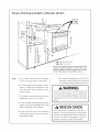
WALL INSTALLATION,
SINGLE OVEN
* HBL: HBL73../74../75../76..
* HBN:HBN 74../75../76..
Secureovento cabinetusingthescrewsprovided.Screws
should be inserted through the mounting holes in the
positionsindicatedin the frame (opendoor to see frame
and mountingholes). Donot overtightenscrews.
Note:
1. Do not slide oven across floor. Damage
to floor covering or floor could result.
6. Be carefld when placing oven. DO NOT
pinch the conduit between the oven back
or v,_alland the inner cabinet v,_allor floor.
2. The oven support surface must be a mininmm 3/4" thick plywood platform, solid,
level and flush with the bottom of the
cabinet cutout.
3. Use extreme caution when moving or in=
stalling the oven. It is very heavy.
4. Be ve® carefld when moving or installing the oven to avoid damage to the oven
frame or damage to the cabinets.
5. Be sure to level the oven. An oven that is
not level may provide poor or inconsistent baking results.
A WARNING
Securely
fasten
oven to cabinet
using
the
screws provided. Failure to do so could result
in oven moving or tipping dming use and cansing damage to the oven or cabinets or personal
NISE EN GARDE
Fixez bien le fore 'aFarmoire
i_ Faide des vis
fournies. Si vous ne le faites pas, cela pom-rait
rdsulter en un d@lacement ou un basculement
du four et pourmit endommager
le _buC les
armoires ou encore causer des biessures.
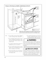
WALL
INSTALLATION,
DOUBLE
OVEN
g
_.5-3/8"
openingwidth
\
* HBL: HBL73../74../75../76..
* HBN: HBN74../75../76..
Secureoven to cabinet using the screws provided.Screwsshould be inserted through the mountingholes in the positionsindicatedin the frame
(opendoor to seeframe and mountingholes).Do not overtightenscrews.
Note:
1. Do not slide oven across floor. Damage
to floor covering or floor could result.
6. Be careflll when placing oven. DO NOT
pinch the conduit between the oven back
or v,_alland the inner cabinet v,_allor floor.
2. The oven support surplice must be a minimmn 3/4" thick plywood platform, solid,
level and flush with the bottom of the
Securely
cabinet cutout.
3. Use extreme caution when moving or installing the oven. It is ve U heavy.
4. Be ve® careflfl when moving or installing the oven to avoid damage to the oven
fiame or damage to the cabinets.
5. Be sure to level the oven. An oven that is
not level may provide
tent baking results.
PB
WARNING
poor or inconsis-
fasten
oven to cabinet
using
the
screws provided. Failure to do so could result
in oven moving or tipping dming use and cansing damage to the oven or cabinets or personal
NISE EN GARDE
Fixez bien le fore 'al'armoire
i_ l'aide des vis
fournies. Si vous ne le faites pas, cela pourmit
rdsulter en un d@lacement ou un basculement
du four et pourrait endommager
le lbuC les
armoires ou encore canser des biessnres.
ELECTRICAL
Before installing the
trician verify that your
equate electrical service
oven will not overload
SUPPLY
WIRING
oven have a qualified elechome is provided with adand that the addition of the
the branch circuit on which
it is to be installed. A separate three-wire or fourwire single phasQ 240 Volt, 60 Hz, or a 208 Volt, 60
Hz branch circuit is required.
NOTE: For use with 208 V, 60 Hz supply voltage,
see ( o_ectmg
to = 08 _o/t Circuit.
For hook-up of the oven you will need to
approved junction box installed where it will
ily reached through the front of the cabinet
the oven will be located. The oven has 3 feet
have an
be easwhere
of con-
duit. Allow two to three feet of slack in the line so
that the oven can be moved if servicing is ever necessalw. DO NOT shorten the flexible conduit.
REQUIREMENTS
When making the wire connections,
use the entire length of the conduit provided (3 feet). The con=
dnit must not be cut.
Before making connections make sme the power
is offand read and obse_we the following:
1. A separate three=wire or fonr wire, single phase,
240 Volt, 60 Hz or 208 Volt, 60 Hz branch circnit
is required for the oven.
2. The oven mnst be connected
with COPPER
WIRE ONLY.
3. In the United States:
Wiring must conform to the National Electrical
Code, ANSI/NFPA No. 70 latest edition.
Yon can obtain a copy of the National Electrical
Code by writing:
National Fire Protection Association
Batterymarch
Park
Qnincy, MA 02269
NISE EN GARDE
WARNING
ELECTRICAL
,
SHOCK
HAZARD
DE CHOC
ELECTRIQUE
The electrical power to the oven branch circuit must be shut offwhile line connections
,
are being made.
, N'ntilisez
pas de mllonge
cet appareil.
* Do not rise an extension
pliance.
cord with this ap=
,
* Electrical ground is required on this appliance. The flee end of the green wire (the
gronnd wire) mnst be connected to a suitable ground.
This wire must remain grounded
,
DANGER
DO NOT ground
Ce fil dlectrique
,
une raise 'a la terre.
doit rester mlid an £onr.
Si les tnyanx d'ean floide comportent des
parties
en plastiqne,
des joints
nonmdtalliqnes on d'antres matdrianx isolants,
NE LES UTILISEZ PAS pont la imse a la
terre.
, N'UTILISEZ
to a gas pipe.
,
DO NOT have a fllse in the NEUTRAL or
GROIE'_DING circnit. A fllse in the NEU=
TP,AL or GROUNDING
circuit conld re=
sult in an electrical shock.
* Check with a qualified electrician if yon are
in doubt as to whether the appliance is properly grounded.
snlt in serions inim T or death.
ndcessite
avec
}'AS DE TUYAUX
DE GAZ
pour la 1rose i_la terre.
,
Failure to follow these instructions
Cet appareil
dlectriqne
L'extrdmitd dn fil vert (ill de raise i_la terre)
doit 6Ire relide i_nne raise i_la terre addqnate.
to the oven.
If cold water pipe is interrupted by plastic,
nonmetallic
gaskets, nnion connections
or
other insulating materials, DO NOT use for
grounding.
Le conmnt 41ectriqne alhnentant le %ur doit
_tre conpd dnrant le branchement.
could re-
, Ne placez pas de filsible sur le fil NEUTRE
ou le fil de MISE A LA TERRE. Un tel ills=
ible ponrmit
,
resnlter
en nn choc dlectriqne.
Si vons avez le moindre doute, I_ites vdfifier
par un dlectficien qne votre appareil est bien
mis i_ la terre.
Le _i_it de ne passe
tions peut entrainer
la mort.
conformer/_
de sdrienses
ces instrucblessnres on
In Canada:
Wiring rrmst conlbrm to Canadian
C22.1- latest edition.
Electrical Code
You can obtain a copy of the Canadian
Electrical
Code by writing:
Canadian Standards Association
178 Rexdale Boulevard
Rexdale (Toronto),
M9W 1R3
4. Wire size (COPPER
Ontario,
Canada
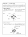
240 Volt selwice is not available. This option must
be accessed
with the oven connected
to power
source, with the oven door (_¢pper ore, i, double
ore,) open, and using the following sequence:
1. Touch CANCEL pad.
2.
Turn rota U kmob clockwise
6 dozeb/e beeps.
3.
Turn rotary knob counter-clockwise
you hear 9 chmb/e beeps.
4.
Touch START pad.
5.
Touch COOKING MODE pad; this sets
oven to 208 Volts.
6.
Touch START pad to save selection of
208 Volts.
WIRE ONLY) and connec-
tions must be suitable for the rating of the appliance per the National Electrical Code requiremerits. The flexible armored cable extending f_om
the oven should be connected directly to the junction box.
5. The junction box should be located so as to allow
as much slack as possible between the junction
box and the oven so it can be moved if se_wicing
is ever required.
6. AU.L. listed conduit connector must be provided
at each end of the power supply cable.
PB
CONNECTING
TO 208 VOLT CIRCUIT
This option is provided for areas where standard
until you hear
until
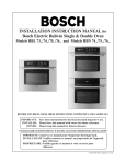
ELECTRICAL
CONNECTIONS
This appliance is manu_i_ctured with a green GR()I_YND wire connected to the oven chassis. After making
sure that the power has been turned oft, connect the flexiNe conduit flom the oven to the junction box using
a U.L. listed conduit connector. Figures A and B and the instructions provided below present the most
common way of connecting the ovens. Your local codes and oldinances, of course, take precedence to these
instructions. Complete electrical connections accolding to local codes and ordinances.
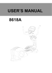
3-WIRE
BRANCH
CIRCUIT
Refer to Figure A, where local codes allow the
connection of GR()UND wire flom the oven to the
GROUND
branch circuit NEUTRAL
ored wire):
wire (grey or white colored wire).
Connect the red and black leads fiom the oven to
* If local
codes
connect
the
green
Redwires
BRANCH
leads in the junction
box.
"_""_"_,
Bareor
_
green wire _
4oWIRE
the corresponding
NEUTRAL
Cablefrom
powersuppJy
Junction box
Figure A
flom the oven to the branch circuit
wire (grey or white col-
permit,
wire flom the oven and the white wire
LI_
Cable
from oven
U.kAisted conduit connector
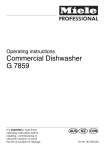
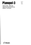
CIRCUIT
Re_}r to Figure B:
, Connect
, Connect the green GR()UND wire flom the oven
to the GROUND wire in the junction box (bare
or green colored wire).
the corresponding
leads in the junction box.
, Connect the white wire fiom the oven to the NEU-
the red and black leads fiom the oven to
TRAL (grey or white) wire in the junction
Ungrounded
Figure
box.
neutrN
B
Junctionbox
Cablefrom
powersupply
¢Thitewires
Redwires
Bare or
greenwire
Blackwires
CaNe from
oven
U.L.-listedconduitconnector
11
FINAL CHECKLIST
4. Set the clock by following
these steps:
a). Touch TIME pad.
To prevent
improper
connections
leading
to dan>
b).
age of electrical components
and so voiding the
warranty, the following steps must be performed:
until CLOCK
appears.
c). Touch TIME pad.
d). Turn rotary knob in either direction. The
time displayed will change in i 0-minute increments and indicate AM or PM. Turn the
1. Check the electrical requirements
and make sure
you have the correct electrical supply and that
the oven is properly
Tm-n rotary knob clockwise
grounded.
knob in the opposite direction
play will change in one-minute
2. Turn on the power supply to the oven. When the
oven is first turned on, a time will flash on the
clock. This is the time of the last power interruption.
and the dis=
increments.
e). Touch TIME pad. The clock is now set.
5. Test the BAKE mode with the %llowing
a). Touch CO()KING
b).
steps:
MODE pad.
Turn rotary knob clockwise
until BAKE ap=
pears.
c). Touch START pad. The cooling lira and oven
lights turn on and the word, PREHEAT, is
displayed.
d). The control will beep and the word, PREHEAT, will disappear when the set tempera°
rare (350 ° F) is reached.
3. Check power at the junction box wires using a
volt meter having a range of 0-250 VAC. If you
have installed the oven for use on 240 Volt supply, you should find that the voltage reading between the black and red wires (Line to Line)
should be 220 to 240 Uolts. If you have modified
the oven(s) for use on 208 Volt, the voltage reading between the black and red wires should be
190 to 208 Volts.
e). Touch CANCEL
6. To check
pad to turn oven off.
the other oven flmctions
refer to the
Us'it_g d_e Ovet_ ('ot_ll_)],s'section of the USE AND
CARE MANUAL.
7_
If the oven is working properly, press the rotary
knob so that it is flush with the oven and turn off
the power supply to the oven.
Place the cover on the junction box and make sure
the cover is securely fastened and turn on the
power to the oven.
9. Leave these INSTALLATION
instructions as well
as the USE AND CARE MANUAL
with the
owner.
BOSCH
5551 McFadden Avenue, Huntington Beach, CA 92649. 800/735-4328
09BH0260.
(c; 2002 BSH Home Appliances Corp.. Litho in USA 1/02
PB