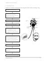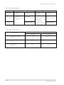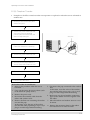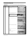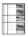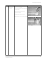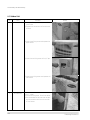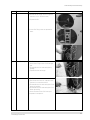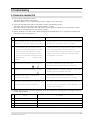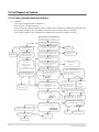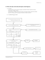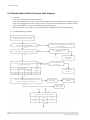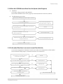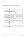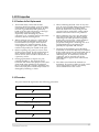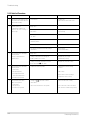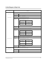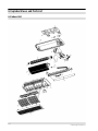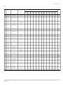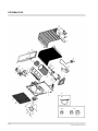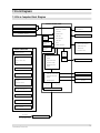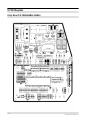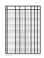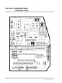
1
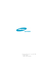
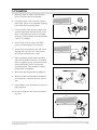
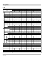
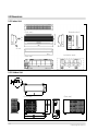
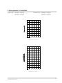
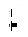
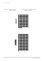
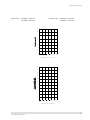
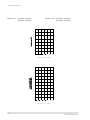
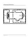
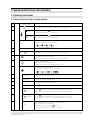
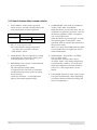
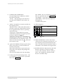
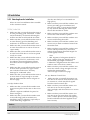
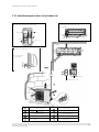
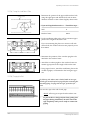
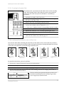
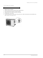
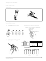
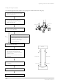
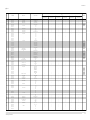
ROOM AIR CONDITIONER
INDOOR UNIT
AS070VE/DOK
AS071VE/DOK
AS074VE/DOK
AS075VE/DOK
AS090VE/DOK
AS091VE/DOK
AS094VE/DOK
AS095VE/DOK
AS120VE/DOK
AS121VE/DOK
AS124VE/DOK
AS125VE/DOK
SERVICE
OUTDOOR UNIT
AX070VE/DOK
AX071VE/DOK
AX074VE/DOK
AX075VE/DOK
AX090VE/DOK
AX091VE/DOK
AX094VE/DOK
AX095VE/DOK
AX120VE/DOK
AX121VE/DOK
AX124VE/DOK
AX125VE/DOK
Manual
AIR CONDITIONER
CONTENTS
1. Precautions
2. Product Specifications
3. Operating Instructions and
Installation
4. Disassembly and Reassembly
5. Troubleshooting
6. Exploded Views and Parts List
7. Block Diagrams
8. PCB Diagrams
9. Wiring Diagrams
10. Schematic Diagrams
© Samsung Electronics Co., Ltd. JAN. 1998.
Printed in Korea.
Code No. DB81-10123A(1)
1. Precautions
1. Warning: Prior to repair, disconnect the
power cord from the circuit breaker.
2. Use proper parts: Use only exact replacement parts. (Also, we recommend replacing
parts rather than repairing them.)
3. Use the proper tools: Use the proper tools
and test equipment, and know how to use
them. Using defective tools or test equipment may cause problems later-intermittent
contact, for example.
Fig. 1-1 Avoid Dangerous Contact
4. Power Cord: Prior to repair, check the
power cord and replace it if necessary.
5. Avoid using an extension cord, and avoid
tapping into a power cord. This practice
may result in malfunction or fire.
6. After completing repairs and reassembly,
check the insulation resistance. Procedure:
Prior to applying power, measure the resistance between the power cord and the
ground terminal. The resistance must be
greater than 30 megohms.
Fig. 1-2 No Tapping and No Extension Cords
7. Make sure that the grounds are adequate.
8. Make sure that the installation conditions
are satisfactory. Relocate the unit if necessary.
9. Keep children away from the unit while it is
being repaired.
10. Be sure to clean the unit and its surrounding area.
Fig. 1-3 No Kids Nearby!
Fig. 1-4 Clean the Unit
Samsung Electronics
1-1
MEMO
1-2
Samsung Electronics
2. Product Specifications
2-1 Table
Model
Item
Type
Cooling
Dehumiditying
Performance
AS090VE/AS091VE/AS094VE/AS095VE
AS090VD/AS091VD/AS094VD/AS095VD
AS120VE/AS121VE/AS124VE/AS125VE
AS120VD/AS121VD/AS124VD/AS125VD
Indoor unit
Indoor unit
Indoor unit
Indoor unit
Indoor unit
Indoor unit
Outdoor unit
Outdoor unit
Outdoor unit
Outdoor unit
Outdoor unit
Wall-mounting
Wall-mounting
Wall-mounting
Wall-mounting
Wall-mounting
BTU/h
7500
7500
9000
9000
12000
12000
I/h
1.2
1.2
1.6
1.6
1.9
1.9
6.0
6.0
6.1
6.1
7.8
7.8
m3/min
Noise
Cooling
dB
35
45
35
45
35
45
35
45
38
49
38
49
BTU/h.W
11.2
11.2
10.2
10.2
10.2
10.2
V-Hz
1-220 / 240-50
1-200 / 220-50
1-220 / 240-50
1-220 / 220-50
1-220 / 240-50
1-200 / 220-50
Power Consumption
Cooling
W
670
670
880
880
1180
1180
Operating Current
Cooling
A
2.8
3.2
4.0
4.2
5.0
5.9
Power factor
Cooling
%
99.7
95.2
91.7
95.2
98.3
90.9
A
17.0
17.0
22.0
22.0
30.0
36.0
Starting current
Power cord
Length
m
2
Number of core wire
Fuse capacity
2
250V 10/16A
-
2
250V 10/16A
-
2
250V 10/16A
250V 10/16A
-
3.15
-
3.15
-
3.15
-
3.15
-
815x298x182
720x525x245
815x298x182
720x525x245
815x298x182
720x525x245
815x298x182
720x525x245
815x298x182
720x525x245
815x298x182
720x525x245
inch
kg
32.08x11.73x7.17 28.35x20.67x9.65
9.6
OD(mm)x L(m)
GAS
ID(mm)x L(m)
27
32.08x11.73x7.17 28.35x20.67x9.65
9.6
32.08x11.73x7.17 28.35x20.67x9.65 32.08x11.73x7.17
27
9.6
28
28.35x20.67x9.65
9.6
28
32.08x11.73x7.17 28.35x20.67x9.65 32.08x11.73x7.17 28.35x20.67x9.65
9.6
31
9.6
31
ø6.35 x 5
ø6.35 x 5
ø6.35 x 5
ø6.35 x 5
ø6.35 x 5
ø6.35 x 5
ø9.52 x 5
ø9.52 x 5
ø9.52 x 5
ø9.52 x 5
ø12.7 x 5
ø12.7 x 5
ø17 x 2000
ø17 x 2000
ø17 x 2000
ø17 x 2000
ø17 x 2000
ø17 x 2000
Type
-
Rotary
-
Rotary
-
Rotary
-
Rotary
-
Rotary
-
Rotary
Motor Type
-
-
-
-
-
-
-
-
-
-
-
-
-
675
-
685
-
895
-
890
-
1210
-
1215
Cross-fan
Propeller
Cross-fan
Propeller
Cross-fan
Propeller
Cross-fan
Propeller
Cross-fan
Propeller
Cross-fan
Propeller
Resin
Die casting
Resin
Die casting
Resin
Steel
Resin
Steel
Resin
Die casting
Resin
Steel
35
15
35
15
35
15
35
15
35
20
35
20
2Row 12Step
1Row 20Step
2Row 12Step
1Row 20Step
2Row 12Step
1Row 20Step
2Row 12Step
1Row 20Step
2Row 12Step
1Row 20Step
2Row 12Step
1Row 20Step
Rated output
Blower
250V 10/16A
-
3.15
x Depth
Compressor
2
-
dimension
Drain hose
-
3.15
mm
Liquid
2
A
Width x Height
Refrigerant pipe
250V 10/16A
Outer
Weight
Size
Outdoor unit
Wall-mounting
Cooling
Power
Power
AS070VD/AS071VD/AS074VD/AS075VD
-
Air volume
Energy efficiency ratio Cooling
AS070VE/AS071VE/AS074VE/AS075VE
W
Type
Motor Type
Rated output
Heat exchanger
W
Refrigerant control unit
CAPILLARY TUBE
CAPILLARY TUBE
CAPILLARY TUBE
CAPILLARY TUBE
CAPILLARY TUBE
CAPILLARY TUBE
Freezer oil capacity
280
280
360
360
410
410
Refrigerant to change(R-22)
670
690
800
740
930
780
Protection device
-
MST24AMN
-12008
-
MST24AMM
-12008
-
MRA12037
-12007
-
MRA12056
-
-12007
Cooling test Condition
INDOOR UNIT : DB27°C WB19°C
OUTDOOR UNIT : DB35°C WB24°C
Maximum operation Condition
INDOOR UNIT : DB32°C WB23°C
OUTDOOR UNIT : DB43°C WB26°C
Samsung Electronics
MRA12030
-12008
-
MRA98706
-12008
2-1
2-2 Dimensions
2-2-1 Indoor Unit
(Front view)
(Remote control)
Air
in
Air out
(Rear view)
Installation plate
2-2-1 Outdoor Unit
(Front view)
2-2
(Rear view)
Samsung Electronics
2-3 Low pressure & Current Data
Indoor Unit : AS070VE/AS071VE
AS074VE/AS075VE
Outdoor Unit : AX070VE/AX071VE
AX074VE/AX075VE
11
10
9
8
7
6
5
4
3
25
30
35
40
45
50
Outdoor Inlet air D. B. temp.(°C)
14
13
12
11
10
9
8
7
6
5
4
3
25
30
35
40
45
50
Outdoor Inlet air D. B. temp.(°C)
Samsung Electronics
2-3
Product Specifications
Indoor Unit : AS070VD/AS071VD
AS074VD/AS075VD
Outdoor : Unit AX070VD/AX071VD
AX074VD/AX075VD
11
10
9
8
7
6
5
4
3
25
30
35
40
45
50
Outdoor Inlet air D. B. temp.(°C)
14
13
12
11
10
9
8
7
6
5
4
3
25
30
35
40
45
50
Outdoor Inlet air D. B. temp.(°C)
2-4
Samsung Electronics
Product Specifications
Indoor Unit : AS090VE/AS091VE
AS094VE/AS095VE
Outdoor : Unit AX090VD/AX091VE
AX094VD/AX095VE
11
10
9
8
7
6
5
4
3
25
30
35
40
45
50
Outdoor Inlet air D. B. temp.(°C)
14
13
12
11
10
9
8
7
6
5
4
3
25
30
35
40
45
50
Outdoor Inlet air D. B. temp.(°C)
Samsung Electronics
2-5
Product Specifications
Indoor Unit : AS090VD/AS091VD
AS094VD/AS095VD
Outdoor Unit : AX090VD/AX091VD
AX094VD/AX095VD
11
10
9
8
7
6
5
4
3
25
30
35
40
45
50
Outdoor Inlet air D. B. temp.(°C)
14
13
12
11
10
9
8
7
6
5
4
3
25
30
35
40
45
50
Outdoor Inlet air D. B. temp.(°C)
2-6
Samsung Electronics
Product Specifications
Indoor Unit : AS120VE/AS121VE
AS124VE/AS125VE
Outdoor Unit : AX120VE/AX121VE
AX124VE/AX125VE
11
10
9
8
7
6
5
4
3
25
30
35
40
45
50
Outdoor Inlet air D. B. temp.(°C)
14
13
12
11
10
9
8
7
6
5
4
3
25
30
35
40
45
50
Outdoor Inlet air D. B. temp.(°C)
Samsung Electronics
2-7
Product Specifications
Indoor Unit : AS120VD/AS121VD
AS124VD/AS125VD
Outdoor Unit : AX120VD/AX121VD
AX124VD/AX125VD
11
10
9
8
7
6
5
4
3
25
30
35
40
45
50
Outdoor Inlet air D. B. temp.(°C)
14
13
12
11
10
9
8
7
6
5
4
3
25
30
35
40
45
50
Outdoor Inlet air D. B. temp.(°C)
2-8
Samsung Electronics
2-4 Refrigerating Cycle Block Diagram
INDOOR UNIT
OUTDOOR UNIT
Capillary tube
T
2-way valve
Liquid side
Heat
exchanger
(Evaporator)
Heat
exchanger
(Condenser)
T
Gas side
3-way valve
Compressor
Cooling
Gas leak check point
Samsung Electronics
2-9
MEMO
2-10
Samsung Electronics
3. Operating Instructions and Installation
3-1 Operating Instructions
3-1-1 Name & Function of Key in remote controller
NO
NAMED OF KEY
FUNCTION OF KEY
On/Off Button. Use this button to start and stop air conditioner.
1
2
(UP)
Temp. up button. If the button is pressed once,
the setting temperature is increased by 1°C
(DOWN)
Temp. up button. If the button is pressed once,
the setting temperature is decreased by 1°C
Each time you press this button,
MODE is changed in the following order.
3
MODE
4
TURBO
Use this button to provide heavy duty cooling & Heating for 30 minutes.
5
OFF
Set up the reserve or cancel the timer on and timer off quickly
6
Use this button for sleep operation.
(The SLEEP mode can be selected at COOL and HEAT mode.)
7
Adjusts air flow vertically.
Each time you press this button,
BLADE-H rotates by 10.58° (Changable range 42.3°)
8
Each time you press this button,
FAN SPEED is changed in the following order.
9
10
11
12
13
C
O
V
E
R
T
I
M
E
R
ON TIMER
Set up the time that operation start.
OFF TIMER
Set up the time that operation stop.
SET
Use this button to reserve the timer on.
CANCEL
Use this button to reserve or cancel the timer on and timer off.
(UP)
If the
button is pressed once, the time increase by one minute
during the time set mode, and ten minutes during the timer set mode.
(DOWN)
If the
button is pressed once, the time decrease by one minute
during the time set mode, and ten minutes during the timer set mode.
14
15
TIME
Samsung Electronics
Without regard to ON/OFF condition in remote controller,
use this button to set current time.
Adjust the current time using
button.
(Data can be transmitted after setting up the time)
3-1
Operating Instructions and Installation
3-1-1 Name & Function of Key in remote controller
1. AUTO MODE : In this mode, operation
COOL mode is selected automatically by the
room temperature of initial operation.
Operation Type
Cool Operation
Room Temp
Tr≥ 24.5°C+∆T
Compressor ON
Tr≤ 24°C+∆T
Compressor OFF
∆T= -1°, -2°C, 0°C+1°C+2°C
∆T is controlled by setting temperature
up/down key of remote controller
* FAN SPEED : AUTO
2. COOL MODE : The unit operates according
to the difference between the setting and
room temperature. (18°C~30°C)
3. DRY MODE : Has 3 states, each determined
by room temperature.
The unit operates in DRY mode.
*Compressor ON/OFF Time is controlled
compulsorily(can not set up the fan speed,
always breeze).
*Protective function : Low temperature
release. (Prevention against freeze)
3-2
4. TURBO MODE : This mode is available in
AUTO, COOL, DRY, FAN MODE.
When this button is pressed at first, the air
conditioner is operated “powerful” state for
30 minutes regardless of the set temperature, room temperature.
When this button is pressed again, or when
the operating time is 30 minutes, turbo
operation mode is canceled and returned to
the previous mode.
*But, if you press the TURBO button in DRY
or FAN mode that is changed with AUTO
mode automatically.
5. SLEEP MODE : Sleep mode is available
only in COOL mode.
The operation will stop after 6 hours.
*In COOL mode : The setting temperature
is automatically raised by 1°C each 1hour
When the temperature has been raised by
total of 2°C, that temperature is maintained.
6. FAN SPEED : Manual (3 step), Auto (4 step)
Fan speed automatically varies depending
on both the difference between setting and
the room temperature.
Samsung Electronics
Operating Instructions and Installation
8. COMPULSORY OPERATION :
For operating the air conditioner without
the remote controller.
*AUTO : The operating is the same function that AUTO MODE in the remote controller.
9.
SWING : BLADE-H is rotated vertically by
the stepping motor.
*Memory louver : When ON/OFF button is
pressed at stop state, the BLADE-H returns
to its original location which is operating
state before stop
*Swing auto : The BLADE-H can rotate
within about 10,500 in the original position
set by the SWING SET button.
*Swing Set : Press the
button under the
remote control is displayed on LCD the
,
and the blades move up and down, about 43°.
If the one more time press the
button, blatles location is stop.
10. Quick OFF TIMER: OFF timer (quick timer)
allows reservation or cancel the timer on
and timer off quickly
When OFF timer button is pressed at operating state, LCD displays the polling state
sequentially.
The LCD also displays the time remaining.
OFF TIMER : The air Conditioner is turned
OFF at a specified time using OFF TIMER .
*ON TIMER : Only timer LED lights on.
*OFF TIMER : Both timer and operation
LED lights on.
*3 minutes delay timer.
14. SELF Diagnosis
LED DISPLAY
Check Point
operation TIMER FAN Turbo
Interruption of electric power and Power on.
Abnormal condition of the room sensor.
Abnormal condition of the indoor unit's heat exchanger sensor.
Indoor unit fan motor lock.
:
LED
blinking
: LED off
15. TIME SHORTENING : If the "Time short"
connector pin is shorted on the main P. C. B,
the compressor's three minutes delay function is cancelled, and each operation time is
shortened to one fiftieth of its original time.
16. BUZZER SOUND : Whenever the ON/OFF
button is pressed or whenever change
occurs to the condition which is set up or
select, the compulsory operation mode,
buzzer is sounded "beep"
11. 24-Hour ON/OFF Real Setting Timer. : The
air conditioner is turned ON at a specified
time using ON TIMER .
Samsung Electronics
3-3
3-2 Installation
(Fix the unit firmly if it is mounted in a
high place.)
3-2-1 Selecting Area for Installation
Select an area for installation that is suitable
to the customer's needs.
3-2-1(a) Indoor Unit
1. Make sure that you install the indoor unit in
an area providing good ventilation. It must
not be blocked by an obstacle affecting the
airflow near the air inlet and the air outlet.
2. Make sure that you install the indoor unit in
an area allowing good air handling and
endurance of vibration of the indoor unit.
3. Make sure that you install the indoor unit in
an area where there is no source of heat or
vapor nearby.
4. Make sure that you install the indoor unit in
an area from which hot or cool air is spread
evenly in a room.
3. Make sure that you install the outdoor unit
in area providing good ventilation and
which is not dusty. It must not be blocked
by any obstacle affecting the airflow near
the air inlet and the air outlet.
4. Make sure that you install the outdoor unit
in area free from animals or plants.
5. Make sure that you install the outdoor unit
in area not blocking the traffic.
6. Make sure that you install the outdoor unit
in area easy to drain condensed water from
the indoor unit.
7. Make sure that you install the outdoor unit
in area which provides easy connection
within the maximum allowable length of a
coolant pipe(15 meters).
Note
1. Add 10 grams of refrigerant (R-22) for
every 1 meter if the pipe length exceeds
the standard pipe length of 5 meters.
2. Maintain a height between the indoor and
outdoor units of less than 3 meters.
5. Make sure that you install the indoor unit in
an area away from TVs, audio units, cordless phones, fluorescent lighting fixtures
and other electrical appliances (at least 1
meter).
6. Make sure that you install the indoor unit in
an area which provides easy pipe connection with the outdoor unit, and easy
drainage for condensed water.
8. Make sure that you install the outdoor unit
in an area which is large enough to accommodate the measurements
shown in figure on the next page.
7. Make sure that you install the indoor unit in
an area which is large enough to accomodate the measurements shown in figure on
the next page.
3-2-1(c) Remote Control Unit
3-2-1(b) Outdoor Unit
1. Make sure that you install the outdoor unit
in area not exposed to the rain or direct sun
light.
(Install a separate sunblind if exposed to
direct sun light.)
2. Make sure that you install the outdoor unit
in area allowing good air moment, not
amplifying noise or vibration, especially to
avoid disturbing neighbours.
1.
Make sure that you install the remote control unit in an area free from obstacles such
as curtains etc, which may block signals
from the remote control unit.
2. Make sure that you install the remote control unit in an area not exposed to
direct sunlight, and where there is no source
of heat.
3. Make sure that you install the remote control unit in an area away from TVs, audio
units, cordless phones, fluorescent lighting
fixtures and other electrical appliances (at
least 1 meter).
Caution :
It is harmful to the air conditioner if it is used in the following environments: greasy areas (including areas near machines),
salty areas such as coast areas, areas where sulfuric gas is present such as hot spring areas. Contact your dealer for advice.
3-4
Samsung Electronics
Operating Instructions and Installation
3-2-2 Installation diagram of indoor unit and outdoor unit
A Indoor unit gas leak test check point
Piping may be laid to the rear, left,
right or down .
3
Indoor unit
Left
Right
2
Rear
Piping
Down
Rear
Tape vinyl
1
B Drain hose installation
200mm or more
250mm
or more
Cut the piping hole
sloped slightly
5
6
Remote control
Remote control holder
4
10
6
Clamper tube
Piping(Gas)3/8”
Piping(Gas)1/2”
7
Installation plate
3
Installation tube
8
Pipe-connection
4
Vinyl tape
9
Screw
5
Putty
10
Drain hose
1
2
Samsung Electronics
Piping (Liquid) 1/4"
7K/9K BTU
12K BTU
3-5
Operating Instructions and Installation
3-2-2(a) Fixing the Installation Plate
1. Determine the position of the pipe and drain hose hole
using the right figure and drill the hole with an inner
diameter of 65mm so that it slants slightly downwards.
Installation plate
Pipe hole
(ø65mm)
2. If you are fixing the indoor unit to a… Then follow Steps…
Wall
3.
Window frame
4 to 6.
3. Fix the installation plate to the wall in a manner appropriate to the weight of the indoor unit.
(Unit : mm)
If you are mounting the plate on a concrete wall with
anchor bolts, the anchor bolts must not project by more
than 20mm.
280
(Unit : mm)
340
4. Determine the positions of the wooden uprights to be
attached to the window frame.
5. Attach the wooden uprights to the window frame in a
manner appropriate to the weight of the indoor unit.
6. Using tapped screws, attach the installation plate to the
wooden uprights, as illustrated in the last figure opposite.
3-2-2(b) Purging the Unit
On delivery, the indoor unit is loaded with an inert gas.
All this gas must therefore be purged before connecting the
assembly piping. To purge the inert gas, proceed as fol lows.
Unscrew the caps at the end of each pipe.
Result : All inert gas escapes from the indoor unit.
•
3-6
To prevent dirt or foreign objects from getting into
the pipes during installation, do NOT remove the
caps completely until you are ready to connect the
piping.
Samsung Electronics
Operating Instructions and Installation
3-2-2(c) Connecting the Assembly Cable.
The outdoor unit is powered from the indoor unit via the assembly
cable. If the outdoor unit is more than five metres away from the
indoor unit, the cable must first be extended to a maximum of
ten metres.
1. Extend the assembly cable if necessary.
2. Open the front grille by pulling on the tabs on the lower right and
left sides of the indoor unit.
3. Remove the screw securing the connector cover.
Indoor unit
4. Pass the assembly cable through the rear of the indoor unit and
connect the assembly cable to terminals 1, 3, 5.
• Each wire is labelled with the corresponding terminal number.
5. Pass the other end of the cable through the 65mm hole in the wall.
6. Replace the connector cover, carefully tightening the screw.
Outdoor unit
7. Close the front grille.
8. For further details on how to plug the other end of the assembly
cable into the outdoor unit, refer to page 3-8.
3-2-2(d) Installing and Connecting the Indoor Unit Drain Hose
Care must be taken when installing the drain hose for the indoor unit to ensure that any condensa tion water is correctly drained outside.l When passing the drain hose through the 65mm hole drilled
in the wall, check that none of the following situations occur.
The hose must
NOT slope upw
ards.
The end of the drain
hose must NOT be
placed in water.
Do NOT bend the
hose in different
directions.
Keep a clearance of at
least 5cm between the
end of the hose and the
ground.
Do NOT place the end
of the drain hose in a
hollow.
To install the drain hose, proceed as follows.
1. If necessary, connect the 2-metre extension to the drain hose.
2. If you are using the extension, insulate the inside part of the extension drain hose with a shield.
3. Pass the drain hose under the refrigerant piping, taking care to keep the drain hose tight.
4. Pass the drain hose through the hole in the wall, making sure that it is sloping downwards, as
shown in the illustrations above.
The hose will be fixed permanently into position once
the whole installation has been tested for gas leaks;
refer to page 16 for further details.
Shield
Drain hose
Samsung Electronics
Extension drain hose
3-7
Operating Instructions and Installation
3-2-2(e) Outdoor unit installation
Wiring connection
1.
2.
3.
4.
5.
6.
Remove the cover-E parts.
Firmly connect the cable connector in the terminal block.
Fasten the M4 ring terminal to the hole marked
Firmly fix the ass'y cable with clamp wire holder.
Assemble the cover-E parts.
To prevent the entry of water, form a trap of the ass'y cable as illustrated in the installation diagram of indoor and outdoor unit.
Cover-E parts
Screw
3-8
Samsung Electronics
Operating Instructions and Installation
3-2-2(f) Flare Modification
• Tools used
Flare modification procedure
1) Cut the pipe using a pipe cutter.
2) Remove burrs at the tip of the pipe cut.
Caution : Burrs not removed may result in
leakage of gas.
Pipe
Oblique Raughness
3) Insert a flare nut into the pipe and
modifty flare.
Reamer
Burr
D
Outer diameter
ø6.35mm
ø9.52mm
ø12.7mm
A
A(mm)
1.3
1.8
2.0
* Unproper flaring
Inclined
Samsung Electronics
Surface
damaged
Cracked
Uneven
thickness
3-9
Operating Instructions and Installation
3-2-2(g) Air-Purge Procedure
• Use the refrigerant of the outdoor unit to purge air inside indoor unit and pipe.
1. Remove the caps from the 2-way valve(B)
and the 3-way valve(A).
2 Turn the 2-way valve cock approx. 45°
counterclockwise to open it. Close it
about 10 seconds later.
Valve stem
Valve stem
Stopper
3 Check refrigerant leakage of each joint parts
(A, B, C & D in right figure)
not
leaking
Leaking
If leaking, tighten the flare nut one more time.
If continues to leak, although the pipe fixing
area has been tightened again,
repair the leaking area.
4. Open the 2-way valve again.
Indoor Unit
5. Open the service valve cap of the 3-way
valve and press the needle valve to
discharge gas for 3 seconds and leave it
for about 1 minute.
Repeat the above procedure for 3 times
to purge air.
6. Open the 2-way valve and 3-way valve
completely
Liquid pipe side
Gas pipe side
2-way valve
3-way valve
Outdoor Unit
7. Close the cap of each valve.
8. Check each valve for leakage.
3-10
Samsung Electronics
Operating Instructions and Installation
3-2-2(h) Refrigerant Refill
• Refill an air-conditioner with refrigerant when refrigerant has been leaked at installing or using
1. Purge air(for new installation only).
2. Turn the 3-way valve clockwise to close,
connect the pressure gauge(low
pressure side) to the service valve, and
open the 3-way valve again.
Suspension hook
3. Connect the tank to refill with Refrigerant
Hand
wheel
4. Set the unit to cool operation mode.
5. Check the pressure indicated by the
pressure gauge(low pressure side).
* Standard pressure is should be
4.5~5.5kg/cm2 in a reqular, high operation
mode.
High
pressure
gauge
Compound
gauge
Finger tight
fittings
For mounting
other and of
hose when
not in use
Connected to
high pressure
side
Charging
line
6. Open the refrigerant tank and fill with refrigerant until the rated pressure is reached.
* It is recommended not to pour the
refrigerant in too quickly, but gradually
while operating a pressure valve.
7. Stop operation of the air conditioner.
8. Close the 3-way valve, disconnect the
pressure gauge, and open the 3-way
valve again.
9. Close the cap of each valve.
Samsung Electronics
3-11
Operating Instructions and Installation
3-2-2(i) Refrigerant Adjustment
Class
Connection
Pipe Length
5m Max.
At installation
At service
Air-Purge
Method
Refrigerant
Adjustment
Air-Purge
Method
Refer to the
detailed Air-Purge
Procedure
Unnecessary
Add 10g of refrigerant
(R-22) for every 1m.
5~10m
Purge air using a
vaccum pump
or an additional
refrigerant cylinder.
Refrigerant
Quantity
refer to
specification sheet
Add 10g of refrigerant
(R-22) for every 1m.
3-2-2(j) Flare unt fixing torque
Outter diameter
3-12
Torque (kg-cm)
Fixing Torque
Final Torque
ø 6.35 (9000Btu, 12000Btu)
(Liquid Side)
160
200
ø 9.52 (9000Btu)
(Gas Side)
300
350
ø 12.7 (12000Btu)
(Gas Side)
500
550
Samsung Electronics
Operating Instructions and Installation
3-2-2(k) "Pump down" Procedure
•
Pump down' shall be carried out when an evaporator is replaced or when the unit is relocated in
another area.
1. Remove the caps from the 2-way valve
and the 3-way valve.
2 Turn the 3-way valve clockwise to close
and connect a pressure gauge(low
pressure side) to the service valve, and
open the 3-way valve again.
2-Way Valve
3. Set the unit to cool operation mode.
(Check if the compressor is operating.)
4. Turn the 2-way valve clockwise to close.
3-Way Valve
5 When the pressure gauge indicates "0"
turn the 3-way valve clockwise to close.
6. Stop operation of the air conditioner.
7. Close the cap of each valve.
Relocation of the air conditioner
• Refer to this procedure when the unit is
relocated.
1. Carry out the pump down procedure (r efer
to the details of 'pump down').
2. Remove the power cord.
3. Disconnect the assembly cable from the
indoor and outdoor units.
4. Remove the flare nut connecting the indoor
unit and the pipe.
At this time, cover the pipe of the indoor
unit and the other pipe using a cap or vinyl
plug to avoid foreign material entering.
Samsung Electronics
5. Disconnect the pipe connected to the outdoor
unit.
At this time, cover the valve of the outdoor
unit and the other pipe using a cap or vinyl
plug to avoid foreign material entering.
6. Make sure you do not bend the connection
pipes in the middle and store together with
the cables.
7. Move the indoor and outdoor units to a new
locatioon.
8. Remove the mounting plate for the indoor
unit and move it to a new location.
3-13
MEMO
3-14
Samsung Electronics
4. Disassembly and Reassembly
Stop operation of the air conditioner and remove the power cord before repairing the unit.
4-1 Indoor Unit
No
Parts
1
Front Grille
Procedure
Remark
1) Stop the air conditioner operation and block
the main power.
2) Seperate tape of front panel upper.
3) Contract the second finger to the left, and
right handle and pull to open the inlet grille.
4) Take the left and right filter out.
* Take the Deadorizing and Electrostatic filter out.
(ONLY “1” and “5” Series models)
5) Loosen one of the right fixing screw and
seperate the terminal cover.
6) Loosen two fixing screws of front grille.
7) Pull the upper left and right of discharge
softly for the outside cover to be pulled out.
8) Pull softly the lower part of discharge and
push it up.
Caution;
Assemble the front panel and fix the
hooks of left and right.
Samsung Electronics
4-1
Disassembly and Reassembly
No
Parts
2
Ass’y Tray Drain.
3
Electrical Parts
(Main PCB)
Procedure
Remark
1) Do “1”, above.
Separate the drain hose from the extension
drain hose.
2) Take the display PCB out.
(Center of indoor unit)
3) Loosen three fixing screws of left and right
4)Pull tray drain out from the back body.
1) Do “1”, “2”, above
2) Take all the connector of PCB upper side out.
(Inclusion Power cord)
3) Separate the outdoor unit connection wire
from the terminal block.
4) If pulling the Main PCB up. it will be taken
out.
(Separate the TRANS hook. it before).
4
Heat Exchanger
1) Do “1” and “2”, “3”, above
2) Loosen two fixing earth screws of right side.
3) Separate the connection pipe.
4) Separate the bush body at the upper side and
holder at the rearside.
5) Loosen the two fixing screws of left side.
6) Lifting the heat exchanger up a little to push
the up side for separation from the indoor
unit.
4-2
Samsung Electronics
Disassembly and Reassembly
No
Parts
3
Fan Motor and
Cross Fan
Procedure
Remark
1) Do “1” “2” ”3” “4”, above.
2) Loosen the fixing three screws and separate
the motor holder.
3) Loosen the fixing screw of fan motor.
(By use of M3 wrench)
4) Separate the fan motor from the fan.
5)Separate the fan from the left holder bearing.
Samsung Electronics
4-3
Disassembly and Reassembly
4-1 Outdoor Unit
No
Parts
Procedure
1
Common Work
1) Loosen the fixing screw and separate the
cover E-parts.
2) Separate the connection wire from the terminal block.
Remark
3) Loosen three fixing screws and separate the
upper cabinet.
4) Loosen the two fixing screws of Ass'y E-part.
5) Loosen seven fixing screws and separate the
side cabinet.
2
4-4
Fan and Motor
1) Do “1”, above.
2) Loosen two fixing screw, of the front cabinet.
3) Push the brackets of the outer cover to separate the protection mesh from the rear side
of front cabinet.
Samsung Electronics
Disassembly and Reassembly
No
Parts
Procedure
Remark
4) Remove the nut flange (Turn to the right to
remove, as it is a left hand screw)
5) Separate the fan.
6) Loosen four fixing screws to separate the
motor.
3
Heat Exchanger
4
Compressor
Samsung Electronics
1) Do “1”, above.
2) Loosen three fixing screws of left and right
side.
3) Disassemble the inlet and outlet pipe by
welding.
4) Separate the heat exchanger.
1) Do “1”, above.
2) Open the terminal cover of compressor and
unscrew the connection terminal.
3) Disassemble the inlet and outlet pipe of compressor by welding.
4) Disassemble the inlet and outlet pipe of condenser by welding
5) Loosen the three bolts of the lower part.
6) separate the compressor.
4-5
MEMO
4-6
Samsung Electronics
5. Troubleshooting
5-1 Items to be checked first
1) Is the voltage of the power correct?
The input voltage shall be 198-264VAC.
The airconditioner may not operate properly if the voltage is out of this range.
2) Is the link cable linking the indoor unit and the outdoor unit linked properly?
The indoor unit and the outdoor unit shall be linked by 5 cables.
Check the terminals if the indoor unit and outdoor unit are properly linked by the same number of cables.
Otherwise the airconditioner may not operate properly.
3) When a problem occurs due to the contents illustrated in the table below it is a symptom not related to the
malfunction of the airconditioner.
NO
Operation of air conditioner
Explanation
1
The COOL operation indication LED (Green) blinks when a
power plug of the indoor unit is plugged in for the first time.
It indicates power is on. The LED stops blinking if the operation
ON/OFF button on the remote control unit is pushed.
2
In a COOL operation mode, the compressor does not
operate at a room temperature higher than the setting
temperature that the IN DOOR FAN should operate.
In a HEAT operation mode, the compressor does not
operate at a room temperature lower than the setting
temperature that
indoor fan should
operate.
In happens after a delay of 3 minutes when the compressor is reoperated. The same phenomenon occurs when a power is on.
As a phenomenon that the compressor is reoperated after a delay of
3 minutes, the indoor fan is adjusted automatically with reference
to a temperature of the air blew
3
Fan speed setting is not allowed in AUTO or DRY mode.
The speed of the indoor fan is set to LL in DRY mode.
Fan speed is 5 steps is selected automatically in AUTO mode.
4
Compressor stops operation intermittently in DRY mode.
Compressor operation is controlled automatically in DRY
depending on the room temperature and humidity.
5
Timer LED only of the indoor unit lights up and the
air conditioner does not operate.
Timer is being activated and the unit is in ready mode.
The unit operates normally if the timer operation is cancelled.
6
The compressor stops intermittently in a COOL mode or DRY
mode, and fan speed of the indoor unit decreases.
The compressor stops intermittently or the fan speed of the indoor unit
decreases to prevent inside/outside air frozen depending on the
inside/outside air temperature.
mode
4) Indoor unit observes operation condition of the air conditioner, and displays self diagnosis details
on the display panel.
NO
Display
Self Diagnosis
1 Operating LED blinking (1Hz)
Restore from power failure (input initial power)
2 TIMER LED blinking (1Hz)
Indoor unit Room sensor Error (open or short)
3 OPERATING and TIMER LED blinking (1Hz)
Indoor unit heat exchanger temperature sensor Error (open or short)
4 FAN LEA blinking (1Hz)
Indoor fan malfunctioning (for spead is Below 38Orpm)
Samsung Electronics
5-1
5-2 Fault Diagnosis by Symptom
5-2-1 No Power (completely dead)-Initial diagnosis
1)
Checklist :
(1) Is input voltage normal? (198-264V~)
(2) Is AC power linked correctly?
(3) Are connections between primary side, secondary side of the power transformer and PCB good.
(4) Is output voltage of DC regulator IC KA7812 (IC01) normal? (11VDC-12.5VDC)
(5) Is output voltage of DC regulator IC KA7805 (IC02) normal? (4.5VDC-5.5VDC)
2)
Troubleshooting procedure
Remove power cord and plug in
again in approx. 5 seconds
Is operation lamp blinking?
NO
YES
Replace
PCB display
Is DC voltage of PCB
display normal?
NO
Is 198~264VAC
applied to the
primary side of the
power transformer?
NO
YES
Does operation start when
run/stop button on the remote
controller unit pushed?
NO
Is transmission display of the
remote controller unit blinking?
NO
•Check linkage
between
power cord and
terminal tap
•Check fuse
Normal
NO
Refer to remote control
unit fault diagnosis
NO
Replace PCB
module.
YES
Is "beep"sound heard from the
main unit?
YES
Is DC voltage of the PCB
module normal?
YES
Are voltages of #62 (compressor),
#60(4 way valve) and #61 (outdoor
fan) of the micom normal? 5VDC YES
Is voltage of #63 (indoor fan) of
the micom normal?
Is 14~18VAC appear in
the secondary side of
the power transformer?
NO
YES
DC5V
Are voltages at RY71
(Compressor) RY73(4-way valve)
and SY72(outdoor fan) normal?
DC12V Is voltage
at SS71(indoor fan)
10ms
YES
YES
NO
Check connections
compressor 4-way
valve, outdoor fan
and indoor fan.
Is voltage at #32 terminal of the Micom
normal? 0VDC
Is voltage at #64 terminal of the Micom
normal? 5VDC
Replace power
transformer
NO
Replace
RY71,
RY73,
RY72 and
SS71
NO
YES
Is output voltage of ICO2 normal?
Is voltage at #25 terminal of the
micom normal?
Check PCB pattern.
Replace main PCB.
10ms
YES
NO
NO
Are voltage at #30 and #31 of
the micom normal?
NO
YES
Replace
ICO2
Is voltage output termina
of D101~D105(IN4007) normal?
YES
NO
Replace resonator (X501)
100ns
YES
Is operation normal?
YES
NO
OK
Replace IN4007
Replace
micom
OK
5-2
Samsung Electronics
Troubleshooting
5-2-2 When the Indoor Unit Fan Does Not Operate. (Initial Diagnosis)
1)
Checklist :
(1) Is the indoor unit fan motor properly connected with the connector (CN73)?
(2) Is the AC voltage correct?
(3) Is HALL IC in indoor fan motor properly connected with the connector (CN43)?
(4) Is the running capacitor properly connected with the terminal?
2)
Troubleshooting procedure
After unplugging out the power cord should
be reconnected within five seconds.
YES
NO
Check as in the procedur “NO power parts”
Refer tp page 5-2.
Does the operating lamp(Green) blink?
YES
Does the Solid State Relay(SS71) work
properly?
NO
Microcomputer is out of order.
Test rod location
+
-
SS71-
SS71-
Normal
Voltage
12V
YES
Is the supply voltage of the fan
motor sufficient?
Test rod location
PCB CN73
NO
PCB is
out of order.
PCB should
be replaced.
Normal
voltage
Condition
Fan operate
YES
AC 180V
MF-C is out of order
Fan motor
is out of order.
Samsung Electronics
Replace MFC
Fan motor
should be
replaced.
5-3
Troubleshooting
5-2-3 When the Outdoor Unit Does Not Operate. (Initial Diagnosis)
1)
2)
Checklist :
(1) Is input voltage normal?(198~264VAC)
(2) Is the set temperature of the remote control higher than room temperature in COOL mode?
(3) Is the set temperature of the remote control lower than room temperature in HEAT mode?
(4) Is the POWER IN connector (terminal-tab) linked correctly?
(5) Is the outdoor unit properly connected with the TERMINAL BLOCK connector(5P)?
Troubleshooting procedure
After unplugging out the power cord should
be reconnected within five seconds.
NO
Does the operating lamp blink
Check as in the procedure "No Power parts"
Refer to page 5-2.
YES
Does the timer lamp blink during operation ?
YES
Room temperature sensor is
out of order
NO
PCB should be
checked.
2
Is the power relay RY71 operated by adjusting NO 1
the room temperature?
Test rod location
Normal
+
-
Condition
Voltage
IC1 Pin No.63
GND
RY73 ON
DC 4.8V
Microcomputer is
out of order.
YES 3
PCB should be
checked.
NO
Power relay is
out of order
Is AC 198 - 264V applied relay between Terminal
Tap(TB71) and RY 71 terminal No. 3
YES
Power relay should be
replaced.
Outdoor unit is
out of order.
1 NO
2 NO
Is the room sensor normal register?
10°C
20°C
30°C
17.96k Ω
12.09k Ω
8.3k Ω
YES 3
5-4
Samsung Electronics
Troubleshooting
5-2-4 When the UP/DOWN Louver Moter Does Not Operate. (Initial Diagnosis)
1)
Checklist :
(1) Is input voltage normal? (198-264VAC)
(2) Is the UP/DOWN louver motor properly connected with the connector (CN61)?
2)
Troubleshooting procedure
Remove power cord and plug in again in approx. 5 seconds.
Y
Is operating lamp blinking?
Check as in the procedure "No
Power parts". Refer to page 5-2.
Y
Does operation start when swing button of the remote
control unit pushed?
Y
Normal
N
N
Voltage at pin #33-#36 of micom (ICO4)
change?(Squarewave)
Micom (IC04) is faulty.
Y
Volatge at pin #10, #11, #12, #13 of IC05 (KID65003)
change?(Squarewave)
N
Driver IC05 (KID65003) is faulty.
Y
UP/DOWN louver motor is faulty.
5-2-5 In the mode, When there is no warm air current. Check this first;
(1) Is the set temperature of Remote Control lower than room temperature in Heat mode?
(2) Is the Indoor PCB properly connected with the CN71 connector?
After training on, the heating operation
should start in five minutes.
YES
Normal
NO
Is the munber #60 of Micom (IC04) DC 4.8 V?
NO
Abnormal Micom
YES
Is the munber #15 of IC07 (KID65003) LOW?
NO
Abnormal IC07
YES
Is the voltage between CN71 #3 and RY71 NO 3 AC198~264?
NO
Abnormal RY73
YES
Abnormal 4way valve of Outdoor Unit.
or connecting Cable
PCB should be replaced.
4 way valve should be replaced
or connecting Cable Check.
Samsung Electronics
5-5
Troubleshooting
5-2-6 If Operation By Remote Control Unit Is Impossible. (Initial Diagnosis)
1)
Troubleshooting procedure
Remove power cord and plug in again approx. 5 Seconds
Is operation lamp blinking?
N
Y
“
“ sound heard from the indoor unit when
ON/OFF button on the remote control unit
pushed?
Y
Check as in the procedure “NO Power
parts”. Refer to page 5-2.
Normal
N
Voltage of battery less than 2.5V (Remote Control Unit)?
Y
Replace battery.
N
LCD display status of REMOCON normal?
N
LCD is faulty.
Y
Transmission display lamp (
) blinking when
ON/OFF button on the remote control unit pushed?
N
Replace button.
Y
Voltage at PIN #30 of Remocon Micom change?
N
Micom is faulty.
Y
Voltage at collecter of Q601 or Q602 change?
N
Q601(C4375Y) or Q602(C1623Y) is
faulty.
IR LED(CL-1L5EU) is faulty.
Y
Voltage at pin #26 of micom (IC04) change (INDOOR UNIT)?
N
Receiver module is faulty.
Y
Micom (IC04) is faulty.
5-6
Samsung Electronics
5-3 PCB Inspection
5-3-1 Cautions for Part Replacement
1. The human body carries much static
electricity. Before touching a part for repair,
replacement or the similar purpose, be sure
to touch a grounded metallic portion by
hand to let the static electricity go through
the matallic portion to the earth.
Espectially when handling any micro
computer or IC, carefully remove such static
electricity before touching them.
2. When repairing any part on a work bench,
be sure to place an insulative sheet on the
bench and always keep the sheet surface
neat without any metal fragments. If any
such fragment touches a part, a secondary
trouble will possibly be caused in the part.
3. Before replacing any parts, be sure to turn
off the power supply. If such replacement is
done with the power supply kept on, an
electric shock, short circuit or destruction of
a part may result.
4. During replacement or repair of a part,
carefully handle it : The printed circuit
board has fine lead wires (jumper wires) and
glass-made parts (diode) on its substrate.
So if a circuit board is roughly handled, such
lead wires and parts will be easily broken or
damaged by bending or shock.
5. When soldering the lead wires of any new
part, be sure to polish them using an emery
paper or the like before solding them.
Since the lead wires of any new part are
covered with an oxide film, solder cannot
adhere to the lead wires if not polished.
6. When soldering any part, care should be
exercised not to apply any high-wattage
soldering iron to the part for a long time.
Some parts are of so low a heat resistance
that they may be broken or have the
properties changed if a soldering iron is so
applied (Otherwise, the pattern may
possibly be separated and raised).
7. The heat of the soldering iron should be
transfered to the entire object to be soldered.
If the solder pieces are not well fused due to
insufficient transfer of the heat from the
soldering iron, no satisfactory electrical
continuity can be assured even if the
soldered objects appear well connected to
each other.
8. The solder used should be limited to a
minimum. If excessive solder is used, it will
cause inter-pattern contact, which may
cause malfunction of the circuit.
5-3-2 Procedure
The parts should be replaced in the following procedure.
Check for any faulty part.
Detach the faulty part.
Replace it with a new part.
Check the operation of the new part.
The repair is completed.
Samsung Electronics
5-7
Troubleshooting
5-3-3 Detailed Procedure
No.
Malfunction
1
Pull out the power plug from the
AC terminal and confirm the fuse
on the PCB assembly
1. Is the broken?
2
Turn the power on.
If lamp blinks trouble is not
related to the items 1 through 4
on the right.
Voltage check
3
4
5
5-8
Set operating mode when RMC
switch pushed.
Except for [FAN]mode and
[TIMER] mode.
Checking point (symptoms)
Causes
1. Voltage over
2. Indoor unit fan motor short-circuit.
1. AC voltage at both end of transformer Primary?
198 - 264V~
1. Irregular power code or power fuse,
or poor wiring.
2. AC voltage at both end of transformer secondary?
14- 18Vac
2. Transformer is faulty.
3. DC voltage at OUT and GND of IC01
(KA7812)? 12VDC
3. Power circuit is faulty.
4. DC voltage at OUT and GND of IC02? 5VDC
4. Power circuit is faulty.
5. DC voltage at Q201 Base and GND change?
squarewave
5. Q201 is faulty.
D101~D104 (IN4007)
Voltage check
1. Voltage of relay (RY71) coil Voltage at
pin#10, pin#7 of IC07 : 12VDC
1. Relay(RY 71) coil is open.
IC6(ULN2003) is faulty.
2. Voltage at Terminal Tap (TB71 or 72) and
RY71 Terminal N0 4 . 198- 264V~
2. Relay(RY 71) contactor is faulty.
Set operating mode when RMC
switch pushed.
1. COOL mode
2. Fan speed [AUTO]
3. Set temperature lower
than room temperature
4. Continuously operation.
1. Compressor does not operate.
1. Temperature of Heat exchange
is lower.
Set operating mode when
RMC switch pushed.
1. [FAN] mode
2. Fan speed [Hi]
3. Continuously operation
1. Voltage at 3 5 both ends of CN73 :
above 180V~
1. Indoor unit fan motor is faulty.
2. Indoor unit fan motor does not operate.
2. Poor connection of indoor fan motor
and connector of RPM sensing (CN43)
2. PCB is faulty.
3. Room sensor or Heat exchanger
temperature sensor is faulty
Samsung Electronics
5-4 Fault Diagnosis of Major Parts
Diagnosis
Parts
Temp.Sensor
Heat ex. Sensor
Indoor Fan Motor
Measure resistance with a tester.
Normal
8KΩ~27KΩ at ambient temperature (+0°C ~ +30°C)
Abnormal
∞, O Ω … open or short
Measure resistance between terminals (CN72) with a tester
Normal
At ambient temperature (10°C ~ 30°C)
between
Resistance
Red, Yellow
190±10Ω
Red, Blue
170 ±10Ω
Abnormal
Measure the voltage between ground and signal wire of the fan motor
Normal
Outdoor Fan Motor
(UP/DOWN swing motor)
Samsung Electronics
Voltage
Gray, Orange
05V~4.5V
Yellow, Orange
5V
Abnormal
Abnormal if voltage does not change from 0V to 5V.
Normal
At ambient temperature (10°C ~ 30°C)
Abnormal
Stepping Motor
between
between
Resistance
Black, White
350 ±10Ω
Black, Red
270 ±10Ω
∞, O Ω … open or short
Measure resistance between red wire and each terminal.
Normal
Approx. 380Ω at ambient temperature (20°C ~30°C)
Abnormal
∞, O Ω … open or short
5-9
6. Exploded Views and Parts List
6-1 Indoor Unit
6-1
Samsung Electronics
Exploded Views and Parts List
■
Parts List
Q’TY
No.
CODE NO
Description
Specification
AS070VE
AS070VD
AS071VE
AS071VD
AS074VE
AS074VD
AS075VE
AS075VD
AS090VE
AS090VD
AS091VE
AS091VD
AS094VE
AS094VD
AS095VE
AS095VD
AS120VE
AS120VD
AS121VE
AS121VD
AS124VE
AS124VD
AS125VE
AS125VD
1
DB64-10140A
DB64-10143A
DB64-70073A
DB64-70075A
DB63-30131A
DB74-10091A
DB63-10472B
DB92-70075C
DB92-70081A
DB93-10470A
DB93-10475A
DB61-10137A
DB61-10143A
DB41-10199A
DB41-10200A
DB94-10074B
DB95-20138A
DB66-30153A
DB75-40072A
DB75-40074A
DB75-40076A
DB67-30058C
DB61-40250A
DB31-10078F
DB94-30141A
DB94-40017A
DB93-10472A
DB93-10486A
DB93-10484A
DB32-10008D
DB39-10062V
DB65-40053A
DB61-10136A
DB61-60093A
DB94-20030B
DB61-40219A
DB70-10618A
GRILLE AIR INLET
ABS
ABS
PC
PC
PP
CLEANER/CARBON
HIPS
ASS´Y
ASS´Y
ASS´Y
ASS´Y
PC
PC
ASS´Y
ASS´Y
ASS´Y
DC12V.600GR
HIPS
ASS´Y
ASS´Y
ASS´Y
PVC
ASS´Y
AMPFS040WTVB
Ø95 619.4mm
ASS´Y
ASS´Y
ASS´Y
ASS´Y
ASS´Y
UCP2
ASS´Y
ABS
HIPS
ASS´Y
HIPS
SGCC-M
1
1
2
1
1
1
1
1
1
1
1
1
1
1
1
1
1
1
1
1
1
1
1
1
1
1
1
1
2
1
1
1
1
1
1
1
1
1
1
1
1
1
1
1
1
1
1
1
1
1
1
1
1
1
1
2
1
1
1
1
1
1
1
1
1
1
1
1
1
1
1
1
1
1
1
1
1
1
1
1
1
2
1
1
1
1
1
1
1
1
1
1
1
1
1
1
1
1
1
1
1
1
1
1
1
1
1
1
2
1
1
1
1
1
1
1
1
1
1
1
1
1
1
1
1
1
1
1
1
1
1
1
1
1
2
1
1
1
1
1
1
1
1
1
1
1
1
1
1
1
1
1
1
1
1
1
1
1
1
1
1
2
1
1
1
1
1
1
1
1
1
1
1
1
1
1
1
1
1
1
1
1
1
1
1
1
1
2
1
1
1
1
1
1
1
1
1
1
1
1
1
1
1
1
1
1
1
1
1
1
1
1
1
1
2
1
1
1
1
1
1
1
1
1
1
1
1
1
1
1
1
1
1
1
1
1
1
1
1
1
2
1
1
1
1
1
1
1
1
1
1
1
1
1
1
1
1
1
1
1
1
1
1
1
1
1
1
2
1
1
1
1
1
1
1
1
1
1
1
1
1
1
1
1
1
1
1
1
1
1
1
1
1
2
1
1
1
1
1
1
1
1
1
1
1
1
1
1
1
1
1
1
1
1
1
1
1
1
1-1
2
3
4
5
6
6-1
6-2
7
7-1
7-2
8
8-1
8-2
9
10
11
12
13
14
15
16
17
18
19
20
21
22
Samsung Electronics
”
PANEL CENTER DISPLAY
”
GUARD AIR FILTER
ASS´Y FILTER
COVER TERMINAL
ASS´Y FRONT PANEL
”
ASS´Y PCB DISPLAY
”
CASE CENTER PCB
”
PCB DISPLAY
”
ASS´Y TRAY DRAIN
ASS´Y STEP MOTOR U/D
BLADE-H
ASS´Y EVAP
”
”
SPACER EVAP
ASS´Y HOLDER MOTOR
MOTOR FAN IN
ASS´Y-C-F-FAN
ASS´Y BEARING
ASS´Y MAIN PCB
”
”
ASS´Y-THERMISTOR
ASS´Y POWER CORD
ASS´Y TERMINAL BLOCK
CASE CONTROL
BODY-BUSH
ASS´Y BACK BODY
HOLDER PIPE
PLATE HANGER
Remark
!
!
!
!
!
!
!
!
!
6-2
6-2 Outdoor Unit
25
25-1
26-1
6-3
26-2
Samsung Electronics
and Parts List
■
Parts List
Q’TY
No.
CODE NO
Description
Specification
1
2
3
4
DB63-30004A
DB60-30004A
DB67-50063A
DB31-10058C
DB31-10140B
DB90-50009H
DB90-50009J
DB67-30077A
DB94-50032B
DB64-60138A
DB72-50560B
DB91-20076A
DB91-20076B
DB91-20076C
DB91-20076D
DB91-20076E
DB91-20076F
2501-001100
2501-001122
2501-001099
2501-001145
2501-001147
2501-001146
DB65-40050A
DB93-50128A
DB47-20001Z
DB47-20002B
DB47-20001Y
DB47-20001V
DB47-20002U
DB47-20001X
DB67-60020A
DB72-50566A
DB72-50558A
DB72-50571A
DB72-50559A
DB72-50557A
DB95-10062Y
DB95-10065K
DB95-10065N
DB95-10063B
DB95-10065Q
DB95-10061F
DB73-10004A
DB60-30029A
DB63-20002A
DB63-10165B
DB60-30018A
DB96-10573A
DB62-31668A
DB62-31669A
DB62-31641A
DB96-10579A
DB96-10540A
DB96-10532D
?
?
DB96-10571B
DB96-30181E
?
?
DB72-50563A
DB90-10024D
DB63-10443A
DB39-20388A
DB39-20387A
DB99-90033A
DB99-90033B
DB60-30010A
DB60-30010B
DB60-30010C
GUARD FAN
NUT FLANGE
PROPELLER-FAN
MOTOR FAN OUT
ABS
2C SM20C M6 NTR
AS+G/F Ø405
AMASS020WTVA
AMASS015WTVA
ASS´Y
ASS´Y
ASS´Y
ASS´Y
SECC-P
FOAM-PE+FOAM-PU
ASS´Y
ASS´Y
ASS´Y
ASS´Y
ASS´Y
ASS´Y
0.9/30µF 450VAC
1.5/30µF 450VAC
1.5/25µF 450VAC
1.2/30µF 450VAC
1.7/30µF 450VAC
1.7/20µF 450VAC
4P
ASS´Y
MRA12030-12008
MST24AMN-12008
MRA12037-12007
MRA98706-12008
MRA12056-12007
MST24AMM-12008
STS304
FELT
RUB+FELT
FELT
EVA+FO-PU
FELT
48A124JV1E5
44A070JW1E1
44B092JW1E6
48A124MW1E5
44B092MW1E6
44A070MW1E1
EPDM
HEX 2C MB ZPC
EPDM
NOTYL
M5. SM20C
ASS´Y
ASS´Y
ASS´Y
ASS’Y
ASS´Y
ASS´Y
ASS´Y
ASS’Y
ASS’Y
ASS’Y
ASS’Y
ASS’Y
ASS’Y
FOAMPE+FOAM PU
SECC-P
ASS´Y
RUBBER
VINYL
1/4” + 1/2”
1/4” + 3/8”
1/4”
3/8”
1/2”
5
6
7
7-1
8
8-1
8-2
8-3
8-4
8-5
9
10
11
12
13
14
15
16
17
18
19
20
21
22
23
24
25
26-1
26-2
Samsung Electronics
”
ASS´Y FRAME
”
ASS´Y PARTITION
”
CABINET UPPER
INSU CABI UPPER
ASS´Y-E PARTS.
”
”
”
”
”
CAPACITOR
”
”
”
”
”
TERMINAL BLOCK
COMP & MOTOR WIRE
O.L.P.
”
”
”
”
”
O.L.P SPRING
CLOTH COMP BOTTOM
”
CLOTH COMP SIDE
”
CLOTH COMP UPPER
COMPRESSOR
”
”
”
”
”
GROMMET-ISOLATOR
NUT-WASHER
GASKET
COVER TERMINAL
NUT-FLANGE
TUBE-DISCHARGE
TUBE-SUCTION
ASSY-CAPI TUBE
ASSY-COND
INSUL CABI-SIDE
ASSY-CABI SIDE
ASSY-COVER E, PARTS
ASSY-CABLE BAG
ASSY-FLARE NUT
FLARE-NUT
AX070VE/AX071VE
AX074VE/AX075VE
AX070VD/AX071VD
AX074VD/AX075VD
AX090VE/AX091VE
AX094VE/AX095VE
AX090VD/AX091VD
AX094VD/AX095VD
AX120VE/AX121VE
AX124VE/AX125VE
AX120VD/AX121VD
AX124VD/AX125VD
1
1
1
1
1
1
1
1
1
1
1
1
1
1
1
1
1
1
3
3
1
1
1
1
1
1
1
1
1
1
1
1
1
1
1
-
1
1
1
1
1
1
1
1
1
1
1
1
1
1
1
1
1
1
3
3
1
1
1
1
1
1
1
1
1
1
1
1
1
1
1
-
1
1
1
1
1
1
1
1
1
1
1
1
1
1
1
1
1
1
3
3
1
1
1
1
1
1
1
1
1
1
1
1
1
1
1
-
1
1
1
1
1
1
1
1
1
1
1
1
1
1
1
1
1
1
3
3
1
1
1
1
1
1
1
1
1
1
1
1
1
1
1
-
1
1
1
1
1
1
1
1
1
1
1
1
1
1
1
1
1
3
3
1
1
1
1
1
1
1
1
1
1
1
1
1
1
1
1
1
1
1
1
1
1
1
1
1
1
1
1
1
1
1
1
1
1
3
3
1
1
1
1
1
1
1
1
1
1
1
1
1
1
1
Remark
!
!
!
!
!
!
!
!
!
!
!
!
!
!
!
!
!
!
!
!
6-4
6-3 Remote Control & PCB Box
6-3-1 Remote Control
Parts List
No
1
2
3
4
5
6
7
8
9
10
11
12
13
14
15
16
17
6-5
CODE NO
Description
DB93-30052B
DB61-10144A
DB61-10145A
DB64-20054A
DB63-10477A
DB74-10084A
DB73-20110B
ASS’Y REMOCON
CASE UP
CASE LOW
DOOR REMOCON
COVER BATTERY
FILTER REMOCON
RUBBER REMOCON
INLAY LCD
INLAY REMOCON
LABEL REMOCON
LABEL DOOR
SCREW TAP
SPRING BATTERY
SPRING BATTERY
SPRING BATTERY
PE BAG
ASS’Y PCB REMOCON
HOLDER REMOCON
DB64-40166B
DB68-10775A
DB68-10777A
PH-M2
DB67-60061A
DB67-60062A
DB67-60063A
90 x 250
DB93-40179B
DB61-40243A
Specification
Q’TY
ABS
ABS
ABS
ABS
PC
SILICON
PC
PC
ART 90
ART 90
PH-M2
SUS 304
SUS 304
SUS 304
90 x 250
1
1
1
1
1
1
1
1
1
1
6
1
1
1
1
1
1
ABS
Remark
Samsung Electronics
Exploded Views and Parts List
6-3-2 PCB Box
2-5
2-6
2-4
2-2
2-1
2-3
3-1
3
2
1
Parts List
7000
Q’TY
9000
12000
1
1
1
-
1
-
-
Ass'y main PCB
-
-
1
-
DB93-10472A
Ass'y main PCB
-
-
-
1
2-1
DB09-10149A
Micom
MB89635R-466
1
1
1
2-2
DB32-10008D
Thermistor-EVAP
103AT 240/240
1
1
1
2-3
DE26-20154A
Trans-power
AC230V DC17V 300mA
1
1
1
2-4
2306-000294
C-film
CFS 99N 450VAC 155K
1
1
1
2-5
3501-001058
Power-relay
DI1U DC12V
1
1
1
2-6
DE32-10037A
Fuse
250V 3.15A
1
1
1
3
DB93-10470A
Ass'y-display and Remocon Module
1
1
1
AS070,071 VE/D
090,091 VE/D
120,121 VE/D
DB93-10475A
Ass'y-display and Remocon Module
1
1
1
AS074,075,094,095
124,125 VE/D
DB32-50021A
Module-remocon
1
1
1
No
CODE NO
1
DB61-10136A
CASE-CONTROL
2
DB93-10484A
Ass'y main PCB
DB93-10486A
3-1
Samsung Electronics
Description
Specification
-
TSOP1238UU1
Remark
6-6
MEMO
6-7
Samsung Electronics
7. Block Diagrams
7-1 Micro Computer Block Diagram
HEAT EXCHANGER SENSOR
INDOOR CONTROL PANEL
•BLADE-H CONTROL
ROOM TEMPERATURE SENSOR
•INDOOR FAN MOTOR
CONTROL
INFRARED SIGNAL
RESET
CIRCUIT
•COMPRESSOR
CONTROL
INDOOR FAN MOTOR
SPEED DETECT
ZERO CROSSING
•TEMPERATURE
CONTROL
OSCILLATION
CIRCUIT
REMOTE CONTROLLER
•TIMER
•BUZZER CONTROL
MODE SELECT
SWITCH
TIMER LED
FAN ONLY LED
TRIGER
SIGNAL
POWER ON/OFF
MODE
(AUTO, COOL, DRY,
FAN
* INDICATOR PANNEL
OPERATION LED
• COMPRESSOR CONTROL
SIGNAL
• STEPPING MOTOR
CONTROL SIGNAL
• BUZZER CONTROL
SIGNAL
SSR
INDOOR FAN MOTOR
TURBO
FAN SPEED SELECT
• COMPRESSOR DRIVE
• STEPPING MOTOR
DRIVE
BLADE-H
COMPRESSOR
STEPPING MOTOR
BUZZER
• BUZZER DRIVE
MOVING SELECT
DC 5V
ON, OFF TIMER SELECT
DC 12V
VOLTAGE REGULATOR
TEMPERATURE SELECT
SLEEP SELECT
TIME SETTING
AC INPUT
DR : 200-220V/50Hz
ER : 220-240V/50HZ
Samsung Electronics
POWER TRANSFORMER
7-1
8. PCB Diagrams
8-1(a) Main PCB-7000Btu(DB93-10484A)
8-1
Samsung Electronics
PCB Diagrams
• PART LIST
No
1
2
3
4
5
6
7
8
9
10
11
12
13
14
15
16
17
18
19
20
21
22
23
24
25
26
27
28
29
30
31
32
33
34
35
36
37
38
39
40
41
42
43
44
45
46
47
48
49
50
51
52
53
54
55
56
57
58
59
60
61
62
63
64
65
DESIGN LOCATION
F701
F701
IC01
IC01
IC01
IC02
CR71
FT71
R903,904,905,906
R203
R202,301,409,501~509,513,518~521,601,604,606,902
R522
R523
R405,407
R201,204,405,401,402,404,603,606
R607
R602
R403
R910,912,913
R406,408
D101~105
SS71
BZ61
TN71
TN71
C202,402
C301,401
C102,104,201,203,403,404,501,502,902
C103
C105
C101
C601
IC04
IC03
X501
IC05,IC06,IC07
Q201,401,601,602
Q603
Q902, Q901
SW91
CN73
CN43
CN41
CN61
CN62
CN71
CN92
TB71,72
RY71
RY72,RY72
J1~J35
HR01
HR02
HR03
HR04
LR01
LR02
LR03
LR04
SW02
SW01
OP01
OP02
OP03
OP04
Samsung Electronics
CODE NO
Description
Specification
DE32-10037A
DE47-40024A
DE13-20008A
DE62-30032A
DE60-10100A
DE13-10016A
2306-000294
DE29-90004A
2001-000776
2001-000588
2001-000065
DE39-60001A
2001-000065
2001-000036
2001-000042
2001-000855
2001-001088
2001-000890
A1000-0244
2004-001137
0402-000137
B4190-0016
DE30-20016A
DE26-20154A
DE60-60012A
2202-000783
2202-000796
2202-000780
2401-000710
2401-001397
2401-000180
2401-001573
DE09-10149A
DE13-20009A
2802-000103
DE13-20024A
A4050-0168
0501-000292
0504-000144
3404-001013
3711-000262
3711-000879
3711-002662
3711-000999
3711-000997
FUSE
HOLDER-FUSE
IC-VOLT REGU
HEAT-SINK
SCREW-PH
IC-VOLT REGU
C-FILM
FILTER NOISE
R-CARBON
R-CARBON
R-CARBON
WIRE SO COPER
R-CARBON
R-CARBON
R-CARBON
R-CARBON
R-CARBON
R-CARBON
R-CARBON
R-METAL FILM
DIODE-RECT
THYRISTOR
BUZZER
TRANS L.V
PIN EYELET
C-CERAMIC
C-CERAMIC
C-CERAMIC
C-ELEC
C-ELEC
C-ELEC
C-ELEC
IC-MCU
IC
RSONATOR-CERAMIC
IC-DRIVE
TR-GENERAL
TRANSISTOR
TRANSISTOR
SWITCH-TACT
CONNECTOR WAFER
CONNECTOR WAFER
CONNECTOR WAFER
CONNECTOR WAFER
CONNECTOR WAFER
CONNECTOR WAFER
CONNECTOR WAFER
CONNECTOR-TERMINAL
RELAY
RELAY
WIRE SO COPER
WIRE SO COPER
WIRE SO COPER
WIRE SO COPER
WIRE SO COPER
WIRE SO COPER
WIRE SO COPER
WIRE SO COPER
WIRE SO COPER
WIRE SO COPER
WIRE SO COPER
WIRE SO COPER
WIRE SO COPER
WIRE SO COPER
WIRE SO COPER
FST 250V 3.15A
FH-51H 7.5A
KA7812A
AL H25
M3*6 FeFzY
KA7805A
CQS 450V 1.5
MD250V 1.6A 6mH
RD 1/2 T(S) 821-J
RD 1/4 TP 332-J
RD 1/4 TP 103-J
P10.6 SN T 52MM
RD 1/4 TP 103-J
RD 1/4 TP 331-J
RD 1/4 TP 102-J
RD 1/4 TP 560-J
RD 1/2 TP 102-J
RD 1/4 TP 682-J
RD 1/8 TP 332-J
RD 1/4 TP 682-F
1N4007
G3MB-202PL
CBE 2220BA STICK
230V DC17V 300mA
OD2.5 L3.0
CA OA 50V 103Z
CA OA 50V 102Z
CA OA 50V 104Z
CE04 25V 222-M
CE 04 25V 471-M
CE 04 35V 102-M
47/50V
MB89635R-466
KA7533Z
10MHz
KID65003AP
KSC945Y
A708Y
R2002
KPT-1115V
YW396-05AV WHT
SMW250-03 BLU
JSW250-02WHT
SMW250-05 WHT
SMW250-05BLU
YW396-03AV BLK
SMW250-09 WHT
250TAP,1PIN
DI1U DC12V
JQ1a-12V
PI0.6 SN T 52MM
PI0.6 SN T 52MM
PI0.6 SN T 52MM
PI0.6 SN T 52MM
PI0.6 SN T 52MM
PI0.6 SN T 52MM
PI0.6 SN T 52MM
PI0.6 SN T 52MM
PI0.6 SN T 52MM
PI0.6 SN T 52MM
PI0.6 SN T 52MM
PI0.6 SN T 52MM
PI0.6 SN T 52MM
PI0.6 SN T 52MM
PI0.6 SN T 52MM
3711-001154
DE59-30001A
3501-001058
B3068-0092
DE39-60001A
DE39-60001A
DE39-60001A
DE39-60001A
DE39-60001A
DE39-60001A
DE39-60001A
DE39-60001A
DE39-60001A
DE39-60001A
DE39-60001A
DE39-60001A
DE39-60001A
DE39-60001A
DE39-60001A
ASH070VE/D AS070VE/D
ASH071VE/D AS071VE/D
ASH074VE/D AS074VE/D
ASH075VE/D AS075VE/D
AS070VB
AS071VB
AS074VB
AS075VB
C
B
A
1
1
1
1
1
1
1
1
4
1
21
1
1
2
8
1
1
1
3
2
5
1
1
1
5
2
2
9
1
1
1
1
1
1
1
3
4
1
2
1
1
1
1
1
1
1
1
2
1
2
35
1
1
1
1
0
1
0
1
1
0
0
0
1
0
1
1
1
1
1
1
1
1
4
1
21
1
1
2
8
1
1
1
3
2
5
1
1
1
5
2
2
9
1
1
1
1
1
1
1
3
4
1
1
1
1
1
1
1
1
0
1
2
1
0
35
1
1
1
1
0
1
0
1
0
1
0
1
0
0
1
1
1
1
1
1
1
1
4
1
21
1
1
2
8
1
1
1
3
2
5
1
1
1
5
2
2
9
1
1
1
1
1
1
1
3
4
1
1
1
1
1
1
1
1
0
1
2
1
0
35
0
0
1
1
1
1
1
0
0
1
1
0
0
0
8-2
8-1(b) Main PCB-9000Btu(DB93-10486A)
12000Btu(DB93-10482A)
8-3
Samsung Electronics
PCB Diagrams
• PART LIST
No
1
2
3
4
5
6
7
8
9
10
11
12
13
14
15
16
17
18
19
20
21
22
23
24
25
26
27
28
29
30
31
32
33
34
35
36
37
38
39
40
41
42
43
44
45
46
47
48
49
50
51
52
53
54
55
56
57
58
59
60
61
62
63
64
65
DESIGN LOCATION
F701
F701
IC01
IC01
IC01
IC02
CR71
FT71
R903,904,905,906
R203
R202,301,409,501~509,513,518~521,601,604,606,902
R522
R523
R405,407
R201,204,405,401,402,404,603,606
R607
R602
R403
R910,912,913
R406,408
D101~105
SS71
BZ61
TN71
TN71
C202,402
C301,401
C102,104,201,203,403,404,501,502,902
C103
C105
C101
C601
IC04
IC03
X501
IC05,IC06,IC07
Q201,401,601,602
Q603
Q902, Q901
SW91
CN73
CN43
CN41
CN61
CN62
CN71
CN92
TB71,72
RY71
RY72,RY72
J1~J35
HR01
HR02
HR03
HR04
LR01
LR02
LR03
LR04
SW02
SW01
OP01
OP02
OP03
OP04
Samsung Electronics
CODE NO
Description
Specification
DE32-10037A
DE47-40024A
DE13-20008A
DE62-30032A
DE60-10100A
DE13-10016A
2306-000294
DE29-90004A
2001-000776
2001-000588
2001-000065
2001-000065
2001-000065
2001-000036
2001-000042
2001-000855
2001-001088
2001-000890
A1000-0224
2004-001137
0402-000137
B4190-0016
DE30-20016A
DE26-20154A
DE60-60012A
2202-000783
2202-000796
2202-000780
2401-000710
2401-001397
2401-000180
2401-001573
DE09-10149A
DE13-20009A
2802-000103
DE13-20024A
A4050-0168
0501-000292
0504-000144
3404-001013
3711-000262
3711-000879
3711-002662
3711-000999
3711-000997
FUSE
HOLDER-FUSE
IC-VOLT REGU
HEAT-SINK
SCREW-PH
IC-VOLT REGU
C-FILM
FILTER NOISE
R-CARBON
R-CARBON
R-CARBON
R-CARBON
R-CARBON
R-CARBON
R-CARBON
R-CARBON
R-CARBON
R-CARBON
R-CARBON
R-METAL FILM
DIODE-RECT
THYRISTOR
BUZZER
TRANS L.V
PIN EYELET
C-CERAMIC
C-CERAMIC
C-CERAMIC
C-ELEC
C-ELEC
C-ELEC
C-ELEC
IC-MCU
IC
RSONATOR-CERAMIC
IC-DRIVE
TR-GENERAL
TRANSISTOR
TRANSISTOR
SWITCH-TACT
CONNECTOR WAFER
CONNECTOR WAFER
CONNECTOR WAFER
CONNECTOR WAFER
CONNECTOR WAFER
CONNECTOR WAFER
CONNECTOR WAFER
CONNECTOR-TERMINAL
RELAY
RELAY
WIRE SO COPER
WIRE SO COPER
WIRE SO COPER
WIRE SO COPER
WIRE SO COPER
WIRE SO COPER
WIRE SO COPER
WIRE SO COPER
WIRE SO COPER
WIRE SO COPER
WIRE SO COPER
WIRE SO COPER
WIRE SO COPER
WIRE SO COPER
WIRE SO COPER
FST 250V 3.15A
FH-51H 7.5A
KA7812A
AL H25
M3*6 FeFzY
KA7805A
CQS 450V 1.5
MD250V 1.6A 6mH
RD 1/2 T(S) 821-J
RD 1/4 TP 332-J
RD 1/4 TP 103-J
RD 1/4 TP 103-J
RD 1/4 TP 103-J
RD 1/4 TP 331-J
RD 1/4 TP 102-J
RD 1/4 TP 560-J
RD 1/2 TP 102-J
RD 1/4 TP 682-J
RD 1/8 TP 332-J
RD 1/4 TP 682-F
1N4007
G3MB-202PL
CBE 2220BA STICK
230V DC17V 300mA
OD2.5 L3.0
CA OA 50V 103Z
CA OA 50V 102Z
CA OA 50V 104Z
CE04 25V 222-M
CE 04 25V 471-M
CE 04 35V 102-M
47/50V
MB89635R-466
KA7533Z
10MHz
KID65003AP
KSC945Y
A708Y
R2002
KPT-1115V
YW396-05AV WHT
SMW250-03 BLU
JSW250-02WHT
SMW250-05 WHT
SMW250-05BLU
YW396-03AV BLK
SMW250-09 WHT
250TAP,1PIN
DI1U DB12V
JQ1a-12V
PI0.6 SN T 52MM
PI0.6 SN T 52MM
PI0.6 SN T 52MM
PI0.6 SN T 52MM
PI0.6 SN T 52MM
PI0.6 SN T 52MM
PI0.6 SN T 52MM
PI0.6 SN T 52MM
PI0.6 SN T 52MM
PI0.6 SN T 52MM
PI0.6 SN T 52MM
PI0.6 SN T 52MM
PI0.6 SN T 52MM
PI0.6 SN T 52MM
PI0.6 SN T 52MM
3711-001154
DE59-30001A
3501-001058
B3068-0092
DE39-60001A
DE39-60001A
DE39-60001A
DE39-60001A
DE39-60001A
DE39-60001A
DE39-60001A
DE39-60001A
DE39-60001A
DE39-60001A
DE39-60001A
DE39-60001A
DE39-60001A
DE39-60001A
DE39-60001A
ASH090VE/D
ASH091VE/D
ASH094VE/D
ASH095VE/D
ASH120VE/D
ASH121VE/D
ASH124VE/D
ASH125VE/D
A/S
AS090VE/D
AS091VE/D
AS094VE/D
AS095VE/D
AS120VE/D
AS121VE/D
AS124VE/D
AS125VE/D
C
D
A
B
1
1
1
1
1
1
1
1
4
1
21
1
1
2
8
1
1
1
3
2
5
1
1
1
5
2
2
9
1
1
1
1
1
1
1
3
4
1
2
1
1
1
1
1
1
1
1
2
1
2
35
0
1
0
1
1
0
1
0
1
0
1
0
0
0
1
1
1
1
1
1
1
1
4
1
21
1
1
2
8
1
1
1
3
2
5
1
1
1
5
2
2
9
1
1
1
1
1
1
1
3
4
1
2
1
1
1
1
1
1
1
1
2
1
2
35
1
0
0
1
0
0
1
0
1
0
0
1
0
0
1
1
1
1
1
1
1
1
4
1
21
0
0
2
8
1
1
1
3
2
5
1
1
1
5
2
2
9
1
1
1
1
1
1
1
3
4
1
1
1
1
1
1
1
1
0
1
2
1
0
35
0
1
0
1
1
0
1
0
0
1
0
0
1
0
1
1
1
1
1
1
1
1
4
1
21
0
0
2
8
1
1
1
3
2
5
1
1
1
5
2
2
9
1
1
1
1
1
1
1
3
4
1
1
1
1
1
1
1
1
0
1
2
1
0
35
1
0
0
1
0
0
1
0
0
1
0
0
0
1
8-4
8-2 ASS’Y DISPLAY & Module
•DB93-10470A : AS070,071,090,091,120,121VE/D
•DB93-10475A : AS074,075,094,095,124,125VE/D
• PCB-DISPLAY (AS070,071,090,091,120,121VE/D) : DB41-10199A
• PCB-DISPLAY (AS074,075,094,095,124,125VE/D) : DB41-10200A
• PART UST
No
Description
CODE-NO
Specification
Q’TY
A
LED - LAMP
DB07-10022A
LTL-52EG-002(ORG/GRN)
1
B
LED - LAMP
0601-001059
SY5511 (YEL)
1
C
LED - LAMP
0601-001060
SM5511 (GRN)
1
D
LED - LAMP
0601-001196
SO5511 (ORG)
1
E
CONNECTOR WAFER
YWLA200-09P
1
F
PCB-DISPLAY
DB41-10200A
FR-1T1.6 W20L170
1
DB41-10199A
FR-1T1.6 W20L170
1
TSOP-1238UU1
1
G
MODULE REMOCON
DB32-50021A
H
C/W DIS & MODULE
DB39-20346A
I
CASE-CENTER PCB
DB61-10143A
AS074,075,094,095,124,125VE/D
1
DB61-10137A
AS070,071,090,091,120,121VE/D
1
-
1
DCR200H(BROWN)
J
PAINT
K
C-CERAMIC
2202-000780
CA OA 50V 104Z
1
L
C-CERAMIC
2201-000283
CA OA 50V 102Z
1
M
DIOD-SWITCHING
0401-000005
1N4148
1
N
R-CARBON
2001-000034
RD 1/4TP 221-J
1
8-5
Samsung Electronics
9. Wiring Diagrams
9-1 Indoor Unit
Samsung Electronics
9-1
9-2 Outdoor Unit
•
AX120/121/124/125VE
CAPACITOR
•
•
AX120/121/124/125VE: 0.9/30µF X 450VAC
AX070/071/074/075VE
CAPACITOR
9-2
AX090/091/094/095VE: 1.5/30µF X 450VAC
AX120/121/124/125VD
CAPACITOR
•
AX070/071/074/075VE: 1.5/25µF X 450VAC
AX090/091/094/095VE
CAPACITOR
•
AX070/071/074/075VD
CAPACITOR
•
AX120/121/124/125VD: 1.2/30µF X 450VAC
AX070/071/074/075VD: 1.7/20µF X 450VAC
AX090/091/094/095VD
CAPACITOR
AX090/091/094/095VD: 1.7/30µF X 450VAC
Samsung Electronics
MEMO
Samsung Electronics
9-3
MEMO
9-4
Samsung Electronics
10. Schematic Diagrams
10-1 Indoor Unit
Samsung Electronics
10-1
10-2 Remote Control
Samsung Electronics
10-2
UPDA TE LOG SHEET
Application date
Page
Part#
Note(Cause & Solution)
S/Bulletin#
Use this page to keep any special servicing information. (Service Bulletin, etc.)
If only parts number changes, Just change parts number directly on parts list.
And if you need more information, please see the service bulletin
Copyright
Trademarks
®œ 1995 by Samsung Electronics Co., Ltd.
All rights reserved.
This manual may not, in whole or in part, be
copied, photocopied, reproduced, translated, or
converted to any electronic or machine readable
from without prior written permission of
Samsung Electronics Co., Ltd.
Samsung is a registered trademark and
SyncMaster 17GLi/CMG7387L and
MacMaster
Cable Adapter are trademark of Samsung
Electronics Co., Ltd.
SyncMaster 17GLi/CMG7387L Service Manual
First edition June 1995.
Printed in Korea.
Macintosh, Centris, Quadra, Duo Dock, and
Power Macintosh are trademark of Apple
computer, Inc.
All other trademarks are the property of their
respective owners.