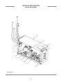
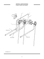
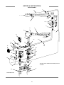
1
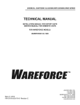
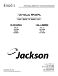
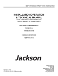
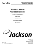
CHEMICAL SANITIZING GLASSWASHER DISHMACHINE SERIES
TECHNICAL MANUAL
INSTALLATION MANUAL FOR EXPORT UNITS
SERVICE MANUAL FOR DOMESTIC UNITS
FOR JACKSON MODELS:
Delta 1200
January 30, 2015
P/N 07610-003-62-15 Revision J
JACKSON WWS, INC.
P.O. BOX 1060
HIGHWAY 25E
BARBOURVILLE, KY. 40906
FAX: (606) 523-9196
PHONE: (606) 523-9795
www.jacksonwws.com
REVISION
REVISION
DATE
MADE
BY
APPLICABLE
ECN
A
10-27-08
CW
B
11-10-08
GS
C
06-05-09
ARL
90605-1430-MD Updated electrical schematic.
D
02-10-10
RLC
091106-1526-CW Corrected part number on page 36
DETAILS
Initial release of manual.
8074
Revised Drawings.
E
02-14-12
RLC
QOF 386
Corrected view on pg 35 to show correct position of mounting
plate,
Corrected item 14 on pg 40 from 05930-011-61-65 to 05700003-60-13
F
05/21/12
RLC
QOF 386
Release of 14 RPM peri-pump assembly
G
03/21/13
RLC
H
06/09/14
MHH
QOF 386
I
09/15/14
KAP
N/A
J
01/30/15
KAP
MHH
QOF NDB-219 Update manufacturer name.
Corrected part # of item 14 on pg. 30.
Added note to pg. 35 about placement of part #’s 36 & 31.
Updated Jackson Logo
Updated part list on page 42
i
NOMENCLATURE FOR THE MODELS COVERED IN THIS MANUAL
GLASSWASHER SERIES
Delta 1200 = 24” Glasswasher
Model:
Serial No.:
Installation Date:
Service Rep. Name:
Phone No.:
ii
TABLE OF CONTENTS
SECTION
I.
DESCRIPTION
PAGE
GENERAL
Specifications
Dimensions
2
3
INSTRUCTIONS SECTION
Installation Instructions
Electrical Connections
Detergent Control
Chemical Dispensing
Operating Instructions
Sequence of Operation
5
6
7
8
9
10
III.
PREVENTATIVE MAINTENANCE
11
IV.
TROUBLESHOOTING SECTION
13
V.
MAINTENANCE INSTRUCTIONS
Replacing the Chemical Feeder Pump Motor
Wash Tank Heater Replacement
Thermostat Replacement
Wash Motor Replacement
17
20
23
25
PARTS SECTION
Control Box Assembly
Outer Shell Assembly
Chemical Feeder Pump Assembly
Rinse Assembly
Wash Assembly
Conveyor and Drive System
Door Assembly
29
31
33
35
37
39
41
ELECTRICAL DIAGRAM
Glasswasher 208-230 Volt, 60 Hertz, Single Phase
43
II.
VI.
VII.
iii
SECTION 1:
SPECIFICATION INFORMATION
1
SECTION 1: SPECIFICATION INFORMATION
SPECIFICATIONS
Delta 1200
OPERATING CAPACITY (RACKS/HOUR)
GLASSES PER HOUR
1200
OPERATING CYCLE (SECONDS)
TOTAL CYCLE TIME
120
TANK CAPACITY (GALLONS)
3.0
WASH PUMP CAPACITY
WASH PUMP
55 GPM
TEMPERATURES
WASH---°F (MINIMUM)
RINSE---°F (MINIMUM)
130
75
ELECTRICAL REQUIREMENTS
WASH PUMP MOTOR HORSEPOWER
1/10
NOTE: Typical Electrical Circuit is based upon (1) 125% of the full amperage load of the machine and (2) typical fixedtrip circuit breaker sizes as listed in the NEC 2002 Edition. Local codes may require more stringent protection than
what is displayed here. Always verify with your electrical service contractor that your circuit protection is adequate
and meets all applicable national and local codes. These numbers are provided in this manual simply for reference
and may change without notice at any given time.
VOLTS
PH
HZ
RINSE
HEATER
RATINGS
208
230
1
1
60
60
220V/3KW
220V/3KW
TOTAL
AMPS
15A
15A
WATER REQUIREMENTS
INLET TEMPERATURE
GALLONS PER HOUR
WATER LINE SIZE NPT (Minimum)
DRAIN LINE SIZE NPT (Minimum)
FLOW PRESSURE P.S.I.
MINIMUM CHLORINE REQUIRED (PPM)
MINIMUM IODIPHOR REQUIRED (PPM)
TYPICAL
ELECTRICAL
CIRCUIT
15A
15A
130°F
10.0
1/2”
1-1/2”
20±5
50
12.5
NOTE: Always refer to the machine data plate for specific electrical and water requirements. The material provided on
this page is for reference only and may be subject to change without notice.
2
SECTION 1: SPECIFICATION INFORMATION
MACHINE DIMENSIONS
25.25"
9.50"
5.00"
Ø1.5 Drain Connection
Water Inlet 1/2" I.P.S. Cold
25.00"
Water Inlet 1/2" I.P.S. Hot
14.64"
12.86"
8.64"
SECTION B-B
SCALE 0.09 : 1
27.41"
25.38
2.00" Wall Clearance
A
19.45"
12" VERTICAL
CLEARANCE
29.26"
B
B
6.59"
Drain
A
05700-003-60-00
3
6.17"
Inlet
SECTION A-A
SCALE 0.09 : 1
SECTION 2:
INSTALLATION/OPERATION
INSTRUCTIONS
4
SECTION 2: INSTALLATION/OPERATION INSTRUCTIONS
INSTALLATION INSTRUCTIONS
VISUAL INSPECTION: Before installing the unit, check the
container and machine for damage. A damaged container is
an indicator that there may be some damage to the machine.
If there is damage to both the container and machine, do not
throw away the container. The dishmachine has been inspected and packed at the factory and is expected to arrive to you
in new, undamaged condition. However, rough handling by
carriers or others may result in there being damage to the unit
while in transit. If such a situation occurs, do not return the unit
to Jackson; instead, contact the carrier and ask them to send
a representative to the site to inspect the damage to the unit
and to complete an inspection report. You must contact the
carrier within 48 hours of receiving the machine. Also, contact
the dealer through which you purchased the unit.
Remove any protective plastic prior to installation.
LEVEL THE DISHMACHINE: The dishmachine is designed to
operate while being level. This is important to prevent any
damage to the machine during operation and to ensure the
best results when washing ware. The unit comes with
adjustable bullet feet, which can be turned using a pair of
channel locks or by hand if the unit can be raised safely.
Ensure that the unit is level from side to side and from front to
back before making any connections.
Packaged unit should be visually inspected for damage.
UNPACKING THE DISHMACHINE: Once the machine has
been removed from the container, ensure that there are no
missing parts from the machine. This may not be obvious at
first. If it is discovered that an item is missing, contact Jackson
immediately to have the missing item shipped to you.
Raise
Lower
PLUMBING THE DISHMACHINE: All plumbing connections
must comply with all applicable local, state, and national
plumbing codes. The plumber is responsible for ensuring that
the incoming water line is thoroughly flushed prior to connecting it to any component of the dishmachine. It is necessary to
remove all foreign debris from the water line that may potentially get trapped in the valves or cause an obstruction. Any
valves that are fouled as a result of foreign matter left in the
water line, and any expenses resulting from this fouling, are
not the responsibility of the manufacturer.
CONNECTING THE DRAIN LINE: The Delta 1200 glasswashers have a gravity drain (2” NPT connection). All piping
from the machine to the drain must be a minimum 2” NPT and
shall not be reduced. There must also be an air gap between
the machine drain line and the floor sink or drain. If a grease
trap is required by code, it should have a flow capacity of 5
gallons per minute.
Use a pry bar and mallet to remove the hold-down blocks.
5
SECTION 2: INSTALLATION/OPERATION INSTRUCTIONS
ELECTRICAL CONNECTIONS
WATER SUPPLY CONNECTION: Ensure that you have read
the section entitled “PLUMBING THE DISHMACHINE” above
before proceeding. Cold water supply must be a minimum of
70°F with a capacity of 180 gallons per hour at 8-12 PSI flow
to the glasswasher. Hot water supply must be a minimum of
130°F with a capacity of 10 gallons per hour at 20±5 PSI flow
pressure. Incoming hot and cold water service connection
(supplied by customer) must be a 1/2” pipe size minimum with
shut off valve. Install the water supply line (1/2” pipe size minimum) to the dishmachine using copper pipe. It is recommended that a water shut-off valve be installed in the water
line between the main supply and the machine to allow access
for service.
be used on all power connections.
In areas where the water pressure fluctuates or is greater than
the recommended pressure, it is suggested that a water pressure regulator be installed.
Ground Lug
Terminal Block
Do not confuse static pressure with flow pressure. Static pressure is the line pressure in a “no flow” condition (all valves and
services are closed). Flow pressure is the pressure in the fill
line when the fill valve is opened during the cycle.
VOLTAGE CHECK: Ensure that the power switch is in the
OFF position and apply power to the dishmachine. Check the
incoming power at the terminal block and ensure it corresponds to the voltage listed on the data plate. If not, contact a
qualified service agency to examine the problem. Do not run
the dishmachine if the voltage is too high or too low. Shut off
the service breaker and mark it as being for the dishmachine.
Advise all proper personnel of any problems and of the location of the service breaker. Replace the electrical box cover
and tighten down the screws.
It is also recommended that shock absorbers (not supplied
with the Delta 1200 units) be installed in the incoming water
lines. This prevents line hammer (hydraulic shock), induced
by the solenoid valves as they operate, from causing damage
to the equipment.
PLUMBING CHECK: Slowly turn on the water supply to the
machine after the incoming fill line and the drain line have
been installed. Check for any leaks and repair as required. All
leaks must be repaired prior to placing the machine in operation.
ELECTRICAL POWER CONNECTION: Electrical and
grounding connections must comply with the applicable portions of the National Electrical Code ANSI/NFPA 70 (latest edition) and/or other electrical codes. Disconnect electrical
power supply and place a tag at the disconnect switch to indicate that you are working on the circuit.
The dishmachine data plate is located on the right side of the
door. Refer to the data plate for machine operating requirements, machine voltage, total amperage load and serial number.
To install the incoming power lines, remove the electrical box
cover. This will require taking a phillipshead screwdriver and
removing the two (2) screws at the bottom corners and lift up
and off. Let the cover rest against the plumbing assembly.
Install conduit from the underside of machine to hole in rear of
electrical box below terminal block and ground lug. Install the
service wires (L1 & L2) to the appropriate terminals as they
are marked on the terminal block. Install the grounding wire
into the lug provided. Tighten the connections. It is recommended that “DE-OX” or another similar anti-oxidation agent
6
SECTION 2: INSTALLATION/OPERATION INSTRUCTIONS
DETERGENT CONTROL
Detergent usage and water hardness are two factors that contribute greatly to how efficiently your dishmachine will operate.
Using detergent in the proper amount can become, in time, a source of substantial savings. A qualified water treatment specialist can tell you what is needed for maximum efficiency from your detergent, but you should still know some basics so you’ll
understand what they are talking about.
First, you must understand that hard water greatly effects the performance of the dishmachine. Water hardness is the amount
of dissolved calcium and magnesium in the water supply. The more dissolved solids in the water, the greater the water hardness. Hard water works against detergent, thereby causing the amount of detergent required for washing to increase. As you
use more detergent, your costs for operating the dishmachine will increase and the results will decrease. The solids in hard
water also may build-up as a scale on wash and rinse heaters, decreasing their ability to heat water. Water temperature is
important in removing soil and sanitizing dishes. If the water cannot get hot enough, your results may not be satisfactory. This
is why Jackson recommends that if you have installed the machine in an area with hard water, that you also install some type
of water treatment equipment to help remove the dissolved solids from the water before it gets to the dishmachine.
Second, hard water may have you adding drying agents to your operating cycle to prevent spotting, when the real problem is
deposited solids on your ware. As the water evaporates off of the ware, the solids will be left behind to form the spotting and
no amount of drying agent will prevent this. Again, using treated water will undoubtedly reduce the occurrences of this problem.
Third, treated water may not be suitable for use in other areas of your operation. For instance, coffee made with soft water may
have an acid or bitter flavor. It may only be feasible to install a small treatment unit for the water going into the dishmachine
itself. Discuss this option with your qualified water treatment specialist.
Even after the water hardness problems have been solved, there still must be proper training of dishmachine operators in how
much detergent is to be used per cycle. Talk with your water treatment specialist and detergent vendor and come up with a
complete training program for operators. Using too much detergent has as detrimental effects as using too little. The proper
amount of detergent must be used for job. It is important to remember that certain menu items may require extra detergent by
their nature and personnel need to be made aware of this. Experience in using the dishmachine under a variety of conditions,
along with good training in the operation of the machine, can go a long way in ensuring your dishmachine operates as efficiently as possible.
Certain dishmachine models require that chemicals be provided for proper operation and sanitization. Some models even
require the installation of third-party chemical feeders to introduce those chemicals to the machine. Jackson does not recommend or endorse any brand name of chemicals or chemical dispensing equipment. Contact your local chemical distributor for
questions concerning these subjects.
Some dishmachines come equipped with integral solid detergent dispensers. These dispensers are designed to accommodate
detergents in a certain sized container. If you have such a unit, remember to explain this to your chemical distributor upon first
contacting them.
As explained before, water temperature is an important factor in ensuring that your dishmachine functions properly. The data
plate located on each unit details what the minimum temperatures must be for either the incoming water supply, the wash tank
and the rinse tank, depending on what model of dishmachine you have installed. These temperatures may also be followed by
temperatures that Jackson recommends to ensure the highest performance from you dishmachine. However, if the minimum
requirements are not met, the chances are your dishes will not be clean or sanitized. Remember, a dish can look clean, but it
may not be sanitized. Instruct your dishmachine operators to observe the required temperatures and to report when they fall
below the minimum allowed. A loss of temperature can indicate a much larger problem such as a failed heater or it could also
indicate that the hot water heater for your operation is not up to capacity and a larger one may need to be installed.
There are several factors to consider when installing your dishmachine to ensure that you get the best possible results from it
and that it operates at peak efficiency for many years. Discuss your concerns with your local chemical distributor and water
treatment specialist before there is a problem.
7
SECTION 2: INSTALLATION/OPERATION INSTRUCTIONS
CHEMICAL DISPENSING EQUIPMENT
TO PREPARE PUMPS FOR OPERATION
The Delta 1200 is supplied with detergent, rinse additive and sanitizer dispensing chemical feeder pumps. Locate the open
ends of the chemical tubes with the tube stiffeners and place each one in the appropriate container.
A. Red Tubing = Detergent
B. Blue Tubing = Rinse Aid
C. White Tubing = Sanitizer
PRIMING CHEMICAL FEEDER PUMPS
Chemical feeder pumps need priming when the machine is first installed, when chemicals are replenished, or if for some reason the chemical lines have been removed and air is allowed to enter.
1. Verify that the proper chemical tube stiffener inlet is in the proper container.
2. Use the push buttons on the right side of control box to prime each pump.
3. To prime the pumps, hold the switch in the momentary position until chemical can be observed exiting the pump.
4. Detergent is dispensed as required during the wash tank fill. The amount of detergent may need to be increased or
decreased depending on water quality and type of detergent. It is adjusted by turning the potentiometer on the speed control
board clockwise to increase, counter-clockwise to decrease.
5. Rinse additive is dispensed proportionally into the final rinse water line. The amount of rinse aid may need to be adjusted
depending on water hardness and results. It is adjusted by turning the potentiometer on the speed control board clockwise to
increase, counter-clockwise to decrease.
6. Sanitizer either chlorine or iodine is dispensed proportionally into the final rinse water line. The amount of sanitizer may need
to be adjusted depending on concentration and the type of sanitizer used. It is adjusted by turning the potentiometer on the
speed control board clockwise to increase, counter-clockwise to decrease.
7. Warning: Some of the chemicals used in dishwashing may cause chemical burns if they come in contact with your
skin. Wear appropriate protective gear when handling these chemicals. If you do come in contact with these chemicals
flush the area with fresh water.
This equipment is not recommend for use with deionized water or other aggressive fluids. Use of deionized water or
other aggressive fluids will result in corrosion and failure of materials and components. Use of deionized water or
other aggressive fluids will void the manufacturer's warranty.
8
SECTION 2: INSTALLATION/OPERATION INSTRUCTIONS
OPERATING INSTRUCTIONS
TO FILL MACHINE WITH WATER:
1. Remove wash tank strainer and place overflow stopper into fitting at the bottom of the wash tank.
2. Open incoming water shut-off valves on cold and hot water lines.
3. Place the power switch to the “FILL” position, machine will automatically fill to the correct level.
4. Check water level, it should be near top of the overflow stopper.
5. Replace wash strainer.
TO RUN THE MACHINE:
1. After filling with water, turn the power switch to the “ON” position, the rack will automatically being to rotate.
2. Place glasses on the rack.
3. When the glasses have completed the cycle, the paddle switch will be activated, turning off the water flow and conveyor
rack.
4. Remove the clean glasses which are against the paddle switch.
5. The rack will begin to rotate again.
SHUTDOWN AND CLEANING OF THE MACHINE:
1. Ensure that all ware placed on the rack is able to complete the cycle and is cleaned prior to moving the power switch to
the “OFF” position. Shut off the water supply to the unit.
2. Remove the drain boards, rack cylinder and rack. Clean before reinstalling into the machine.
3. Remove the sump and drain tank strainers. Clean completely before reinstalling into the machine.
4. Remove the stand pipe by grasping by the handle and removing from the drain tank. Clean before reinstalling into the
machine.
CAUTION: Water in the drain tank may be hot, allow the water to cool down and always remove the stand pipe
through the use of the handle. Never place your hand in the water within the drain tank.
5. Remove the curtains and wash using a mild soap and rinse with clear water. Allow to dry completely before reinstalling into
the machine.
6. Remove the wash and rinse arms. Inspect them for clogged or obstructed nozzles. Remove end caps and flush the inside
of the wash and rinse arms with clean water. Reinstall end caps when completed.
7. Wipe out the inside of the tub, removing any and all debris.
8. Reinstall all components previously removed after they have been allowed to dry.
9. Remove, clean and reinstall upper (wash) and lower (drain) strainers.
9
SECTION 3:
PREVENTATIVE MAINTENANCE
10
SECTION 3: PREVENTATIVE MAINTENANCE
PREVENTATIVE MAINTENANCE
The dishmachines covered in this manual are designed to operate with a minimum of interaction with the operator. However,
this does not mean that some items will not wear out in time. Jackson highly recommends that any maintenance and repairs
not specifically discussed in this manual should be performed by QUALIFIED SERVICE PERSONNEL ONLY. Performing maintenance on your dishmachine may void your warranty if it is still in effect, so if you have a question or concern, do not hesitate
to contact Jackson.
There are many things that operators can do to prevent catastrophic damage to the dishmachine. One of the major causes of
component failure has to do with prescrapping procedures. A dishmachine is not a garbage disposal; any large pieces of material that are put into the machine shall remain in the machine until they are either broken up (after spreading out on your ware!)
or physically removed. Strainers are installed to help catch debris, but they do no good If they are clogged. Have operators regularly inspect the pan strainers to ensure (1) that they are free of soil and debris and (2) they are laying flat in the tub.
When cleaning out strainers, do NOT beat them on waste cans. The strainers are made of metal and can be forgiving; but once
severe damage is done, it is next to impossible for the strainer to work in the way it was designed to. Wipe out strainers with
a rag and rinse under a faucet if necessary. For stubborn debris, a toothpick should be able to dislodge any obstructions from
the perforations. Always ensure that strainers are placed back in the machine before operation and that they lay flat in the tub.
You may wish to also refer to the page entitled “Detergent Control” in order to learn more about how your water hardness will
effect the performance of your machine. Hard water makes dishmachines work harder and decreases efficiency.
Again, it is important to remind operators that trying to perform corrective maintenance on the dishmachine could lead to larger problems or even cause harm to the operator. If a problem is discovered; secure the dishmachine using proper shut down
procedures as listed in this manual and contact Jackson.
Some problems, however, may having nothing to do with the machine itself and no amount of preventative maintanence is
going to help. A common problem has to do with temperatures being too low. Verify that the water temperatures coming to your
dishmachine match the requirements listed on the machine data plate. There can be a variety of reasons why your water temperature could be too low and you should discuss it with Jackson to determine what can be done.
By following the operating and cleaning instructions in this manual, you should get the most efficient results from your machine.
As a reminder, here are some steps to take to ensure that you are using the dishmachine the way it was designed to work:
1. Ensure that the water temperatures match those listed on the machine data plate.
2. Ensure that all strainers are in place before operating the machine.
3. Ensure that all wash and/or rinse arms are secure in the machine before operating.
4. Ensure that drains are closed/sealed before operating.
5. Remove as much soil from dishes by hand as possible before loading into racks.
6. Do not overfill racks.
7. Ensure that glasses are placed upside down in the rack.
8. Ensure that all chemicals being injected to machine have been verified as being at the correct concentrations.
9. Clean out the machine at the end of every workday as per the instructions in the manual.
10. Always contact Jackson whenever a serious problem arises.
11. Follow all safety procedures, whether listed in this manual or put forth by local, state or national codes/regulations.
11
SECTION 4:
TROUBLESHOOTING
12
SECTION 4: TROUBLESHOOTING
COMMON PROBLEMS
Inspection, testing and repair of electrical equipment should only be performed by a qualified service technician. Many of the tests require that the unit have power to it and live electrical components be exposed.
USE EXTREME CAUTION WHEN TESTING THE MACHINE.
Problem: Dish machine will not run, no voltage at wash relay terminals L1 and T1.
1. Electrical power not installed to machine, service (main) power disconnect off. Ensure electrical wiring is run to machine and
service (main) disconnect is on.
2. Branch circuit breaker tripped or fuse is blown. Reset or replace as required. Have an electrician check machine amp draw
if problem keeps occuring.
3. Loose or broken connection to dish machine. Tighten, replace or repair as required.
Problem: Machine cycles continuously.
1. Limit switch actuator is loose or has fallen off. Reassemble/bend metal lever if necessary.
2. Faulty limit switch. Replace switch.
Problem: Machine will not fill, other functions work.
1. No water supply to machine. Ensure that water is hooked up properly to machine and that it is turned on.
2. Faulty Hot Water solenoid valve diaphragm or coil. Replace diaphragm and clean out valve. Measure continuity on coil, if
there is none, replace the coil.
3. Faulty float switch. Ohm out the switch to ensure that upper and lower floats are working. If not, check float wiring to see if
it is correct; if so, replace float.
Problem: Machine fills continuously even with no power to the dish machine.
1. Solenoid valve jammed/stuck in the open position. Check diaphragm and coil, replace as required.
2. Faulty float switch. Ohm out the switch to ensure that upper and lower floats are working. If not, check float wiring to see if
it is correct; if so, replace float switch.
Problem: Wash motor does not run, other functions work.
1. Loose wire connection to limit switch or relay. Tighten wires.
2. Faulty pump motor. Replace pump motor.
3. Mechanical binding in the pump. If motor has correct incoming voltage, and the overload is tripping, repair or replace the
pump.
Problem: Wash motor does not run; other functions work.
1. High or low voltage problem. Check voltage at motor and at power terminal block. Ensure it meets the electrical voltage
specifiactions for the dish machine.
2. Faulty limit switch. Replace limit switch.
Problem: Wash motor runs continuously.
1. Wash relay welded closed. Turn machine off. If wash relay does not release, replace.
Problem: Low water pressure.
1.
2.
3.
4.
Water level is too low. Ensure that incoming water line pressure meets the requirements on dish machine data plate.
Wash arms clogged. Remove wash arms and clean.
Obstruction in pump housing. Disassemble and clear.
O-ring at wash tank drain cut or missing. Replace.
13
SECTION 4: TROUBLESHOOTING
COMMON PROBLEMS
Problem: Low wash water pressure at wash arm spray nozzles.
1. Pump impeller worn or broken. Replace pump.
2. Clogged jets in wash arms. Clean out wash arms.
3. Float stuck on float switch. Remove, clean and reinstall float switch.
4. Water level too low in the wash tank. Ensure that the incoming water line flow pressure meets the requirements on the dishmachine data plate.
Problem: Machine keeps tripping service breaker.
1.
2.
3.
4.
Power supply shorted to ground. Check for loose wires/burned connection. Replace or repair as required.
Pump impeller jammed. Disassembly and remove obstruction.
Wash pump motor faulty. Check motor voltage and amp draw.
Service breaker too small. Replace with correctly sized breaker.
Problem: Machine will not hold water.
1. Drain stopper not in place. Set drain stopper correctly in drain.
2. Drain fitting O-ring cut or missing. Replace O-ring.
3. Drain stopper bent or deformed. Replace.
Problem: Sanitizer pump runs continuously.
1. Shorted prime switch. If there is not line voltage between BLACK/YELLOW and ORANGE/BLUE wires to prime switch,
replace.
2. Faulty speed control board. Check operation of board. If not working properly, replace.
Problem: Sanitizer pump does not run during cycle, but runs when primed. Even when turntable is off.
1. Loose or broken wire. Replace or tighten.
2. Faulty speed control board. Check operation of board. If not working properly, replace.
3. Faulty prime switch. Check continuity through each pole of the speed control board. If it fails, replace the speed control board.
Problem: Prime switch does not activate sanitizer pump.
1. Faulty prime switch. With the prime switch in the prime position, check for voltage between BLACK/YELLOW and
ORANGE/BLUE wires. If line voltage, replace switch.
2. Loose wire to prime switch. Tighten wire connection.
Problem: Sanitizer pump doesn't run during cycle or through prime switch.
1. Loose motor terminal wires. Tighten connections.
Problem: Sanitizer pump doesn't run during cycle or through prime switch.
1. Faulty sanitizer pump motor. If you read line voltage at the sanitizer motor terminals during the sanitizer feed cycle, replace
the motor.
2. Faulty prime switch. Check the continuity through each pole of the switch. If faulty, replace the speed control board.
Problem: Detergent not feeding, rinse aid feeds okay.
1. Faulty speed control board. Check operation of board. If not working properly, replace.
2. Defective hose or squeeze tube. Replace hose or squeeze tube as needed.
3. Machine not in fill mode. Normal operation.
14
SECTION 4: TROUBLESHOOTING
COMMON PROBLEMS
Problem: Rinse aid pump not feeding, detergent feeds okay.
1. Faulty speed control board. Check operation of board. If not working properly, replace.
2. Defective hose or squeeze tube. Replace hose or squeeze tube as needed.
Problem: Wash heater does not work. (Note: push wash heater contactor bar down and take amperage reading. Amps
should be correct as stated on the dish machine data plate).
1. If no amp draw, check wash heater for continuity. If open or shorted, replace the heater. If closed, replace the heater contactor.
2. Wash heater relay will not energize (no voltage at contactor coil). Check for continuity at wash thermostat. If open, replace.
3. Low voltage problem. Check incoming voltage to ensure it as what the data plate calls for.
15
SECTION 5:
SERVICE PROCEDURES
16
SECTION 5: SERVICE PROCEDURES
REPLACING THE CHEMICAL FEEDER PUMP MOTOR
Jackson glasswasher machines come equipped with
chemical feeder pumps to ensure proper ware washing
results. Occasionally, the motors operating these pumps may
need replacing to maintain optimum performance.
Jackson offers all of the repair parts necessary for
performing this task.
The instructions provided here are for maintenance
personnel only. Unauthorized persons should not attempt any
of the steps contained in these instructions.
STEPS
1. Remove the front door.
Warning: many of the instructions and steps within this document require the use of tools. Only authorized
personnel should ever perform any maintenance procedure on the dishmachine!
PREPARATION
1. Power must be secured to the unit at the service
breaker. Tag or lock out the service breaker to prevent accidental or unauthorized energizing of the machine.
2. Ensure that incoming water to the machine is
secured either by use of a shut-off valve or disconnecting the
incoming water line.
3. The unit must be drained completely with the drain
stopper removed.
Removing the screws for the electrical box cover.
TOOLS REQUIRED
The following tools will be needed to perform this
maintenance evolution:
1. Phillipshead Screwdriver
2. Needlenose Pliers
3. Wire Cutters
4. Wire Strippers
5. Crimping Tool
TIME REQUIRED
It is estimated that it will take (1) person thirty minutes
per motor to perform this task, not including all of the items
indicated in the section entitled “PREPARATION”.
Removing the electrical box cover.
2. Remove the electrical box cover with the phillipshead screwdriver.
IMPORTANT NOTES
3. The cover must be laid down close to the control box
because of the attached wires. Be careful not to yank out or
damage any of the wires as you move the cover.
1. Read these instructions thoroughly before attempting this maintenance task. Become familiar with the parts and
what actions need to be taken. This will save time in the long
run!
2. These instructions show steps on only (1) of the
three motors. However, the steps are the same for each one.
4. Determine which motor you wish to replace, or which one
you wish to start with. Trace the wires leading from the motor
to its corresponding prime switch. Trace the other wire from
the motor to determine where it is connected.
5. With the needlenose pliers, remove the motor wire from the
prime switch, being careful not to damage the prime switch in
the process. (If the prime switch is damaged, it will need to be
17
SECTION 5: SERVICE PROCEDURES
REPLACING THE CHEMICAL FEEDER PUMP MOTOR (CONTINUED)
replaced. Refer to the parts section of the technical manual for
information regarding part numbers for ordering new prime
switches.)
6. Turn the cover over and using the phillipshead screwdriver,
remove the cover to the pump requiring a motor change.
Removing the priming switch wire
Removing the front cover.
7. With the cover removed, gently pull out the rubber tube from
inside the pump.
Unhooking motor power wire
Pulling the rubber tube out of the pump.
8. Remove the roller by pulling it off of the shaft.
9. Using the phillipshead screwdriver, remove the four mounting screws for the motor.
10. Once the screws are removed, the motor should drop
away.
11. Cut away any tie-wraps that are holding the power wires
and remove the motor.
12. Take your new motor and attach new terminals to the wires
as required.
13. Remount the motor to the pump.
Removing the pump front cover screws.
18
SECTION 5: SERVICE PROCEDURES
REPLACING THE CHEMICAL FEEDER PUMP MOTOR (CONTINUED)
14. Place the roller and the rubber tube back in the pump casing. Place the pump cover back on and tighten down with the
four screws you previously removed.
15. Reattach the power wire and the wire for the priming
switch.
16. Put the cover back on the control box and secure with the
two screws previously removed.
17. Ensuring that all non-essential personnel are clear of the
area, restore power to the unit. Turn the unit on and by using
the priming switch, verify that the feeder pump operates and
pumps fluid.
18. Replace the front door.
Removing the roller.
AFTER MAINTENANCE ACTIONS
None.
SPECIAL NOTES
Work performed on Jackson dishmachines by unauthorized or unqualified personnel may void the warranty.
Before beginning this or any other maintenance evolution on a
unit under warranty, you should contact a certified Jackson
technician or Jackson Technical Service. You can find a list of
qualified service agencies in the back of you unit’s installation
manual.
SPECIAL PARTS
Removing the motor mounting screws.
Removing the motor.
19
SECTION 5: SERVICE PROCEDURES
WASH TANK HEATER REPLACEMENT
Jackson glasswasher machines come equipped with
heaters to ensure proper ware washing results. Occasionally,
some of these components may need replacing to maintain
optimum performance.
Jackson offers all of the repair parts necessary for
performing this task.
The instructions provided here are for maintenance
personnel only. Unauthorized persons should not attempt any
of the steps contained in these instructions.
STEPS
1. Remove the front door.
Warning: many of the instructions and steps
within this document require the use of tools. Only authorized personnel should ever perform any maintenance
procedure on the dishmachine!
PREPARATION
1. Power must be secured to the unit at the service
breaker. Tag or lock out the service breaker to prevent accidental or unauthorized energizing of the machine.
2. Ensure that incoming water to the machine is
secured either by use of a shut-off valve or disconnecting the
incoming water line.
3. The unit must be drained completely with the drain
stopper removed.
Removing the heater cover.
2. Remove the heater box cover with the 3/8” nutdriver to
expose the heater. Set the cover and hardware to the side.
TOOLS REQUIRED
The following tools will be needed to perform this
maintenance evolution:
1. 3/8” Nutdriver
2. Ratchet
3. 1/2” Socket
4. 3/8” Socket
5. Torque Wrench
6. Amp Meter
TIME REQUIRED
It is estimated that it will take (1) person thirty minutes
to perform this task, not including all of the items indicated in
the section entitled “PREPARATION”.
Removing the lower strainer.
IMPORTANT NOTES
3. Remove the lower strainer.
4. Remove the upper (wash) strainer as well. Set both strainers to the side where they will not be damaged or present a
trip hazard.
1. Read these instructions thoroughly before attempting this maintenance task. Become familiar with the parts and
what actions need to be taken. This will save time in the long
run!
20
SECTION 5: SERVICE PROCEDURES
WASH TANK HEATER REPLACEMENT (CONTINUED)
6. Next, use the ratchet and 1/2” socket to remove the heater
mounting nuts.
Removing upper (wash) strainer.
Reaching into the wash tank.
7. Removing the heater may require that you reach into the
wash tank, grasp it and give it a push out of the wash tank.
Removing the heater nuts.
5. Using the 3/8” nutdriver, remove the nuts securing the
heater wires to the heater. Then carefully pull the wires out of
Pulling the heater out.
8. Once the heater is pushed away from the tank wall, pull it
out with your hands.
9. Remove the old heater gasket and throw away.
10. Apply the new heater gasket.
11. Take the new heater and slide it through the hole in the
wash tank and line it up so the wash tank studs fit in the holes
on the heater flange.
12. Place the mounting nuts and lockwashers on the studs and
secure them with the ratchet and 1/2” socket.
the way.
13. Place the heater wires on the heater and tighten them
down using the 3/8” nutdriver.
Using the ratchet to remove the heater mounting nuts.
21
SECTION 5: SERVICE PROCEDURES
WASH TANK HEATER REPLACEMENT (CONTINUED)
AFTER MAINTENANCE ACTIONS
Service personnel may want to drain the machine
and allow it to cool down. Secure power to the unit at the service breaker and then verify the torque of all fasteners covered
in this instruction.
SPECIAL NOTES
Work performed on Jackson dishmachines by unauthorized or unqualified personnel may void the warranty.
Before beginning this or any other maintenance evolution on a
unit under warranty, you should contact a certified Jackson
technician or Jackson Technical Service. You can find a list of
qualified service agencies in the back of you unit’s installation
manual.
Removing the heater gasket
14. Using the torque wrench or a torque nutdriver (if available)
torque the nuts holding the wires, jumpers and bus bars to 16
in-lbs.
SPECIAL PARTS
15. Ensuring that all non-essential personnel are clear of the
area, place the drain stopper back in the wash tank and
restore power and water to the unit. Turn the unit on and allow
it to fill normally.
18. Verify that there are no leaks around the heater. If there
are, attempt to tighten it down (with power secured to the unit
at the service breaker to prevent injury) as the tank will change
shape slightly as it heats up.
19. Use the amp meter to take readings off of the power lines
to the heater, verifying the amperage draw to the machine
data plate.
20. Wait until the heater contactor kicks out (meaning that the
tub has reached the appropriate temperature) and allow the
machine to operate approximately ten minutes to verify that
there are no leaks and that the heater is maintaining the tank
temperature.
21. Replace the heater cover.
23. Replace the front door.
22
SECTION 5: SERVICE PROCEDURES
THERMOSTAT REPLACEMENT
Jackson glasswasher machines come equipped with
thermostats to ensure proper ware washing results.
Occasionally, some of these components may need replacing
to maintain optimum performance.
Jackson offers all of the repair parts necessary for
performing this task.
The instructions provided here are for maintenance
personnel only. Unauthorized persons should not attempt any
of the steps contained in these instructions.
STEPS
1. Remove the front door.
Warning: many of the instructions and steps
within this document require the use of tools. Only authorized personnel should ever perform any maintenance
procedure on the dishmachine!
PREPARATION
1. Power must be secured to the unit at the service
breaker. Tag or lock out the service breaker to prevent accidental or unauthorized energizing of the machine.
2. Ensure that incoming water to the machine is
secured either by use of a shut-off valve or disconnecting the
incoming water line.
3. The unit must be drained completely with the drain
stopper removed.
Removing the heater cover.
2. Remove the heater box cover with the 3/8” nutdriver to
expose the heater. Set the cover and hardware to the side.
TOOLS REQUIRED
The following tools will be needed to perform this
maintenance evolution:
1. 3/8” Nutdriver
2. 7/16” Nutdriver
3. 7/16” Combination Wrench
4. Needlenose Pliers
5. Phillipshead Screwdriver
TIME REQUIRED
It is estimated that it will take (1) person twenty minutes to perform this task, not including all of the items indicated in the section entitled “PREPARATION”.
Removing the terminals.
IMPORTANT NOTES
3. Using the pair of needlenosed pliers (if necessary), remove
the terminals from the thermostat. Be careful not to damage
the terminals or the wires or else they will have to be replaced.
1. Read these instructions thoroughly before
attempting this maintenance task. Become familiar with the
parts and what actions need to be taken. This will save time in
the long run!
23
SECTION 5: SERVICE PROCEDURES
THERMOSTAT REPLACEMENT (CONTINUED)
ture is maintained in accordance with the specifications on the
machine data plate.
4. Use the 7/16” combination wrench to loosen and remove
the imperial brass fitting. Once this is complete, you should be
able to completely remove the thermostat.
9. Replace the heater cover.
10. Replace the front door.
5. Take the new thermostat and place its probe in the new
imperial brass fitting provided in your kit. Use the 7/16” combination wrench to tighten it down after getting the fitting handtight in the tank.
AFTER MAINTENANCE ACTIONS
None
SPECIAL NOTES
Work performed on Jackson dishmachines by unauthorized or unqualified personnel may void the warranty.
Before beginning this or any other maintenance evolution on a
unit under warranty, you should contact a certified Jackson
technician or Jackson Technical Service. You can find a list of
qualified service agencies in the back of you unit’s installation
manual.
SPECIAL PARTS
Removing the probe and imperial brass fitting.
Removing the thermostat
The completed thermostat replacement
6. Reconnect the wires per the machine schematic on the
back of the door.
7. Place the drain stopper back in the wash tank. Restore
power and water to the unit. Then allow the unit to operate normally.
8. Verify that the thermostat operates the heater contactor.
Once you have determined the heater contactor is working,
adjust the wash tank thermostat to ensure that the tempera-
24
SECTION 5: SERVICE PROCEDURES
WASH MOTOR REPLACEMENT
Jackson glasswasher machines come equipped with
wash pumps that have powerful motors attached to them to
ensure proper ware washing results. Occasionally, these
assemblies may require replacing to maintain optimum performance.
Jackson offers all of the repair parts necessary for
performing this task.
The instructions provided here are for maintenance
personnel only. Unauthorized persons should not attempt any
of the steps contained in these instructions.
STEPS
1. To access the assembly, you need to get access to the rear
of the unit. This may require that water, drain and power lines
be disconnected so that the unit can be moved for access.
Warning: many of the instructions and steps
within this document require the use of tools. Only authorized personnel should ever perform any maintenance
procedure on the dishmachine!
PREPARATION
1. Power must be secured to the unit at the service
breaker. Tag or lock out the service breaker to prevent accidental or unauthorized energizing of the machine.
2. Ensure that incoming water to the machine is
secured either by use of a shut-off valve or disconnecting the
incoming water line.
3. The unit must be drained completely with the drain
stopper removed.
Gain access to the rear of the machine.
2. Using the 5/16” nutdriver, loosen the clamps on the suction
hose.
TOOLS REQUIRED
The following tools will be needed to perform this
maintenance evolution:
1. 1/4” Nutdriver
2. 5/16” Nutdriver
3. Needlenose Pliers
4. 7/16” Combination Wrench
5. (2) 9/16” Combination Wrench
TIME REQUIRED
It is estimated that it will take (1) person ninety minutes per motor to perform this task, not including all of the
items indicated in the section entitled “PREPARATION”.
IMPORTANT NOTES
1. Read these instructions thoroughly before attempting this maintenance task. Become familiar with the parts and
what actions need to be taken. This will save time in the long
run!
Loosening the suction hose clamps.
3. Using the same nutdriver, loosen the disharge hose where
it connects to the tub weldement.
4. Pull the discharge hose out and away from the tub.
5. Remove the motor assembly mounting nuts using the 7/16”
combination wrench.
6. With the nuts removed, grasp the motor assembly and lift up
on it to clear the mounting studs.
25
SECTION 5: SERVICE PROCEDURES
WASH MOTOR REPLACEMENT (CONTINUED)
Lifting up on the motor.
Loosening the discharge hose clamp.
7. Turn the motor so that you will have access to the wiring
cover on the back. Be careful not to pull or yank too hard as
the motor is still connected to the unit by way of the power
lines.
Pulling the discharge hose out.
Suction hose coming off when moving the assembly.
8. Take the needlenose pliers and remove the power wires
from the terminals within the motor.
9. The motor should now be free. Replace with a new new
motor by performing the removal steps in reverse.
10. Place the disharge hose assembly back on the discharge
of the pump and tighten down.
11. Lift the assembly into place within the unit, ensuring that
the suction hose is attached and lines up. Move the assembly
so the mounting bracket slides over the mounting studs.
Position the assembly so that the suction hose is not kinked.
Removing the assembly mounting nuts.
21. Replace and tightne down the nuts securing the bracket to
the frame.
26
SECTION 5: SERVICE PROCEDURES
WASH MOTOR REPLACEMENT (CONTINUED)
22. Tighten the clamps for the suction hose.
23. Connect the disharge hose to the tub and tighten down the
hose clamp.
AFTER MAINTENANCE ACTIONS
Verify the operation of the new wash motor and
pump assembly by running the unit for approximately 15 minutes. Check for leaks and corredt as necessary.
SPECIAL NOTES
Work performed on Jackson dishmachines by unauthorized or unqualified personnel may void the warranty.
Before beginning this or any other maintenance evolution on
a unit under warranty, you should contact a certified Jackson
technician or Jackson Technical Service. You can find a list of
qualified service agencies in the back of you unit’s installation
manual.
SPECIAL PARTS
27
SECTION 6:
PARTS SECTION
28
SECTION 6: PARTS SECTION
CONTROL BOX ASSEMBLY
14
13
12
1
2
11
3
4
5
6
7
8
9
10
07610-003-61-14
29
SECTION 6: PARTS SECTION
CONTROL BOX ASSEMBLY
Number
QTY
Part Number
Description
1
2
05975-011-49-03
Fitting
2
3
05975-011-65-51
Fitting
3
1
05700-003-56-00
Bracket
4
1
05910-003-43-01
Capacitor
5
1
05940-200-76-00
Ground Lug
6
1
05700-011-40-05
Seperator
7
1
05950-011-61-67
Transformer
8
1
05945-111-47-51
Relay
9
2
05945-002-74-20
Contactor
10
1
05700-003-55-38
Access Panel
11
1
09905-100-75-93
Decal, Warning, Disconnect Power
12
1
09905-011-68-99
Decal, Caution
13
1
05975-011-49-03
Terminal Board
14
1
05700-003-55-37
Complete Assembly
30
SECTION 6: PARTS SECTION
OUTER SHELL ASSEMBLY
05700-003-57-951
OUTER SHELL
05700-003-60-389
2
05975-210-03-00
05700-003-58-73
3
809905-003-57-30
08415-003-60-357
505700-003-60-39
05340-108-01-03
4
05930-011-61-69
6
07610-003-61-26
31
SECTION 6: PARTS SECTION
OUTER SHELL ASSEMBLY
Number
QTY
Part Number
Description
1
1
05700-003-57-95
Outer Cover
2
1
05975-210-03-00
Grommett
3
1
05700-003-58-73
Access Cover
4
4
05340-108-01-03
Bullet Foot
5
1
05700-003-60-39
Switch Cover
6
1
05930-011-61-69
Power Switch
7
1
08415-003-60-35
Curtain
8
1
09905-003-57-30
Jackson Decal
9
1
05700-003-57-95
Curtain Rod
32
SECTION 6: PARTS SECTION
CHEMICAL FEEDER PUMP ASSEMBLY
1
2
3
7
6
Detergent Kit
4
5
Sanitizer Kit
Rinse Aid Kit
07610-003-61-19
33
SECTION 6: PARTS SECTION
CHEMICAL FEEDER PUMP ASSEMBLY
Number
QTY
Part Number
Description
1
1
05700-003-87-08
14 RPM Peri-Pump
2
1
05700-003-55-29
Cover and Peri-Pump Assembly
3
1
05700-003-55-34
Cover only
4
1
06401-003-61-21
Sanitizer Tube Replacement Kit
5
1
06401-003-61-22
Rinse Aid Tube Replacement Kit
6
1
06401-003-61-23
Detergent Tube Replacement Kit
7
1
05700-011-65-21
Squeeze Tube
34
SECTION 6: PARTS SECTION
RINSE ASSEMBLY
4
3
1
5
2
6, 7, 8
9
2
11
12
13
14
21
19
23
22
24
15
16
20
17
18
25
10
37
38
26
40
34, 39
27
28
7
29
35
33, 34
The base of the machine will be between items
36 and 31.
30
32
31
COLD WATER
07610-003-61-05
HOT WATER
36
35
SECTION 6: PARTS SECTION
WASH ASSEMBLY
Number
QTY
Part Number
Description
1
2
1
09330-003-45-71
Upper Rinse Casting
2
05700-003-56-57
Rinse Arm
3
1
05700-003-45-71
Hose
4
1
05330-003-41-73
Grommett
5
2
05700-003-55-31
Vacuum Breaker
6
4
04730-011-61-57
Vacuum Breaker Nipple
7
6
05310-011-61-45
Hex Nut
8
2
05700-003-58-03
Vacuum Breaker Mounting Bracket
9
4
04730-011-61-47
Vacuum Breaker Fitting
10
2
04730-002-18-54
Fitting
11
2
05330-011-74-55
O-Ring
12
1
09330-003-45-67
Lower Wash Casting
13
1
05700-003-49-32
Tube
14
1
06885-011-64-29
Pressure Gauge
15
1
05700-003-58-79
Manifold Mounting Bracket
16
2
05305-011-66-03
10-32 Screw
17
1
05700-031-60-37
Manifold Block
18
1
06685-111-35-30
Thermometer
19
1
05700-003-60-45
Tube
20
2
04730-003-07-07
Elbow
21
1
04710-003-60-46
Tube
22
2
04730-003-60-47
Fitting
23
6
05700-003-55-57
End Cap
24
1
05700-003-49-23
Hose, 1/2” ID x 36” Long, Polybraid
25
1
05700-003-49-18
Hose, 1/2” ID x 45” Long, Polybraid
26
1
05700-003-49-23
Fitting
27
1
09330-003-51-19
T-Fitting
28
1
05700-003-57-29
Tubing, 1/2” ID x 28” Long
29
1
09905-011-65-47
Decal, Blue
30
1
05700-003-49-28
Hose, 3/8” x 13” Long, Polybraid
31
2
04730-011-61-52
Coupling
32
1
04820-011-61-56
Check Valve
33
1
04820-011-61-58
Ball Valve
34
3
04730-002-18-00
Close Nipple
35
2
04730-011-61-53
Tee
36
1
05700-003-60-21
Mounting Plate
37
2
04730-011-61-54
S-45 Valve
38
2
05975-111-62-70
S-45 Valve Cover
39
2
04730-003-60-57
Union
40
1
09905-011-65-46
Decal, Red
36
SECTION 6: PARTS SECTION
WASH SYSTEM
1
4
2
3
WASH AND FILL
SYSTEM
6
5
7
10, 11
12
2
9
8
LOCATED INSIDE TANK
30
13
29
28
14
15
27
16
25, 26
24
17
23
22
31
21
COLD WATER
20
07610-003-61-11
37
HOT WATER
18
19
SECTION 6: PARTS SECTION
WASH SYSTEM
Number
QTY
Part Number
Description
1
1
05700-021-61-78
Wash Tank Strainer
2
2
05700-003-42-83
Wash Arm
3
4
05330-011-74-55
O-Ring, 13/16” OD
4
1
05330-003-41-73
Grommett
5
1
05700-003-49-32
Tube, Stainless Steel
6
1
05700-021-62-22
Wash Tank Overflow
7
1
05330-400-05-00
Wash Tank O-Ring
8
1
05311-011-62-65
Washer
9
1
04720-003-57-29
Hose, 3/4” OD
10
1
05700-003-59-21
Overflow Support
11
2
05310-373-01-00
10-24 Locknut
12
1
06680-121-70-16
Float
13
1
05700-003-49-27
5” Long Hose
14
1
04730-003-40-64
Pump Hose Connector
15
1
05700-003-59-96
Pump Discharge Hose
16
1
05700-003-60-25
Pump Suction Hose
17
1
06105-003-44-22
Wash Pump
18
1
05305-002-46-43
6-32 x 1/4” Screw
19
1
09905-011-86-86
Ground Decal
20
1
05700-003-60-00
Drain Weldment
21
1
05700-011-71-93
Washier, 1/2” Flat
22
1
05310-924-02-05
Thermostat Fitting
23
1
05930-510-02-79
Thermostat
24
1
05700-003-60-24
Heater Cover
25
4
05311-275-01-00
Lockwasher
26
4
05310-275-01-00
Hex Nut
27
1
04540-021-61-66
Wash Heater
28
1
05330-011-61-34
Wash Heater Gasket
29
1
06685-111-35-30
Thermometer
30
1
05700-003-60-12
Wash Tank
31
1
05310-011-72-58
Hexnut, 1/2”-13 S/S
38
SECTION 6: PARTS SECTION
CONVEYOR AND DRIVE SYSTEM
1
05700-005-49-10
CONVEYOR AND
DRIVE SYSTEM
2
09330-003-45-66
5
05700-003-48-99
3
6
09330-003-58-52
09330-003-51-17
4
05700-003-59-93
19
7
09330-003-58-32
05700-003-58-54
8
05330-003-41-75
05340-003-41-83
9
18
16, 17
15
05700-003-58-50
05305-171-10-00
05930-303-38-00
05975-011-63-56
14
05930-011-61-65
10
05700-003-48-87
13
05975-011-63-56
11
06105-003-44-23
12
05700-003-48-57
07610-003-61-13
39
SECTION 6: PARTS SECTION
CONVEYOR AND DRIVE SYSTEM
Number
QTY
Part Number
Description
1
1
05700-003-49-10
Cylinder
2
1
09330-003-45-66
Rack
3
3
09330-003-51-17
Guide Block
4
1
05700-003-59-93
Strainer Weldment
5
1
05700-003-48-99
Drain Defelctor, Wash
6
1
09330-003-58-52
Plate, Skid
7
1
09330-003-58-32
Drive Gear
8
1
05330-003-41-75
Washer
05340-003-41-83
Extension Spring
9
10
1
05700-003-48-87
Gear Motor Box
11
1
06105-003-44-23
Gear Motor
12
1
05700-003-48-57
Gear Motor Box Cover
13
2
05975-011-63-56
Strain Relief
14
1
05700-003-60-13
Switch mounting bracket
15
1
05975-011-63-56
Strain Relief
16
1
05930-303-38-00
Limit Switch
17
2
05305-171-10-00
Limit Switch Mounting Screws
18
1
05700-003-58-50
Activator Weldment
19
1
05700-003-58-54
Limit Switch Actuator
40
SECTION 6: PARTS SECTION
DOOR ASSEMBLY
41
SECTION 6: PARTS SECTION
DOOR ASSEMBLY
Number
QTY
Part Number
Description
1
1
05700-002-24-40
Door Weldment
2
1
05340-001-96-30
Handle, Door Glasswasher
3
1
09905-011-61-70
Decal - Off/Fill/On
4
2
05340-021-62-04
Hinge
5
8
05311-273-02-00
Starwasher, External Tooth
6
8
05305-173-03-00
Screw 10-24 X 3/8
7
1
09905-021-64-88
Decal, Operating Instructions
42
SECTION 7:
ELECTRICAL SCHEMATICS
43
SECTION 7: ELECTRICAL SCHEMATICS
44