1
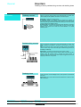
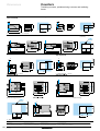
General
Counters
Totalising counters, predetermining counters and totalising timers
Introduction
The XBK counters associated with detection products (photo-electric detectors, inductive sensors, limit switches) or
dialogue products (pushbuttons, selector switches, etc) can be used to provide a complementary function of the control
system : counting.
Functions
XBK counters complement the Magelis range of display units and operator dialogue terminals by offering simple display
and entry functions. They are fully compatible with labelled Telemecanique detection and man-machine dialogue
products.
Technology
The offer is divided between two technologies : electromechanics and electronics.
Electromechanics is used for slow counting applications, of around several tens of hertz, whereas electronics is adapted
to counting frequencies of around a kilohertz.
These two technologies can be subdivided into three distinct product families :
- totalising counters,
- predetermining counters,
- totalising timers.
These three families offer products with varying characteristics :
- display capacity,
- type and number of outputs,
- types of input,
- reset to zero option,
- adding, subtracting, bidirectional or programmable counting mode,
- display in hundredths of an hour (hour counters).
This enables the products to be more application-specific.
Characteristics :
pages 35053/2 and 35053/3
5052 Ver2.00-EN.fm/2
References :
pages 35054/2 and 35054/3
Dimensions :
pages 35055/2 and 35055/3
Schneider Electric
General
Counters
Totalising counters, predetermining counters and totalising timers
Applications
Totalising counters
These are used for counting events from electrical pulses or contacts. The
value is displayed and updated in increments on each new pulse.
Application : counting the number of parts
In automatic mode : the totalising counter performs this operation in
conjunction with a photo-electric detector, inductive sensor or limit switch, which
detects the passing of a part and translates this by adding one unit to the number
of parts counted by the totalising counter.
In manual mode : the totalising counters performs this operation in conjunction
with a pushbutton. A press on the button adds one more unit to the value
displayed. This system can be used with a ticket distributor or a manual
assembly station.
Predetermining counters
Supply
Signals
Limit switch
These are used for counting events from electrical pulses or contacts. The
value is displayed and updated in increments or decrements on each new
pulse.
They can be used to enter a preset value manually. When this predefined
value is reached, they send an electrical signal. Predetermining counters can
be adding or subtracting.
Applications : upcounting or downcounting the number of parts.
The predetermining counter counts the number of parts in the same way as a
totaliser. When the selected value is reached, the preset counter, in
conjunction with the various sensors, sends a signal to trigger actions, such as
stopping a machine or conveyor belt.
Stop belt
Totalising timers
These are used to count and display the time, with a precision of a hundredth
of an hour.
Applications : they can be used to measure the duration of an action or of the
use of a machine.
Oven
Characteristics :
pages 35053/2 and 35053/3
Schneider Electric
References :
pages 35054/2 and 35054/3
Dimensions :
pages 35055/2 and 35055/3
35052 Ver2.00-EN.fm/
Characteristics
Counters
Totalising counters, predetermining counters and totalising
timers
Type of device
Type of display
XBK-T totalising counters
mechanical
LCD
XBK-H totalising timer
mechanical
LCD
EN 50081-2, EN 50082-2 EN 50081-2, EN 50082-2
EN 61010
UL, CSA (pending)
except XBK-T60000U00M UL, C-UL (pending)
EN 50081-2,
EN 50081-2, EN 50082-2
EN 50082-2, VDE 0435 EN 61010
Environment
Conforming to standards
Product certifications
Temperature
UL, CSA (pending)
UL, C-UL (pending)
Operation
°C
- 10…+ 50 except XBK-T60000U00M : - 10...+ 70
- 10…+ 50
Storage
°C
- 20…+ 60 except XBK-T60000U00M : - 40…+ 85
- 25…+ 70
- 20…+ 60
Degree of protection
according to IEC 529
IP 40 except
IP 54
XBK-T60000U00M : IP 65
IP 65
IP 54
Vibration resistance
according to IEC 68-2-6
5 gn (10 to 150 Hz)
1 gn (10 to 150 Hz)
3 gn (10 to 150 Hz)
1 gn (10 to 150 Hz)
Shock resistance
according to IEC 68-2-27
30 gn (6 ms)
10 gn (18 ms)
30 gn (11 ms)
10 gn (18 ms)
Protection against electric shocks
Class II according to IEC 536
Mounting and fixing
Flush-mounting element
Flush-mounting unit fixed
by a clamp
Connection
By AMP lugs on a
cable connector
On screw terminal block
Battery
Flush-mounting unit fixed by a self-locking
clamp
Characteristics
Supply voltage
V
c 24 ± 10 %
c 48 ± 10 %
a 115 ± 10 %
Consumption
W/VA
XBK-T50000U10M,
–
XBK-T50000U08M and
XBK-T70000U00M : 1.5
XBK-T50000U11M : 2.5
XBK-T60000U10M and
XBK-T80000U00M : 2.5
XBK-T60000U11M : 2.75
XBK-T60000U00M : 0.155
XBK-T70000001M : 0.56 –
XBK-T70000002M : 1
XBK-T70000004M : 0.08
Counting frequency
Hz
10, 20, 25
7500
–
Backup capacity
Permanent
7 years
Permanent
7 years
Number of digits
5, 6, 7 or 8
8
7
8
Precision of display
99999… 99999999
99999999
99999.99 h
999999.99 h
4
7
5
7
Counting mode
Adding
Adding
(Input resistance : 50 kΩ)
Adding 1/100 of an hour
Reset to zero
With or without
With
Without
With
Type of reset to zero
Manual
Manual with electric
locking
–
Manual with electric
locking
Inputs
Function
Count
Type
Contact
Transistor : PNP ≥ 8 V
or NPN ≤ 0.7 V
Contact
Transistor : PNP ≥ 8 V
or NPN ≤ 0.7 V
–
± 40 V max
–
± 40 V max
10 million pulses except
–
XBK-T60000U10M and
T80000U00M : 200 million
–
–
–
–
–
Character height
Amplitude
mm
V
Mechanical life
Minimum length of pulse
General :
pages35052/2and35052/3
5053 Ver3.00-EN.fm/2
ms
References :
pages 35054/2 and 35054/3
a 24 ± 10 % 50 Hz
Battery
a 115 ± 10 % 50 Hz
a 230 ± 10 % 50 Hz
Enable
15 at 30 Hz, 0.07 at 7.5 kHz
Dimensions :
pages 35055/2 and 35055/3
Compatibility :
pages 35056/2 and 35056/3
Schneider Electric
Characteristics
Counters
Totalising counters, predetermining counters and totalising
timers
Type of device
Type of display
XBK-P5
Mechanical
XBK-P6
LED or LCD
Environment
Conforming to standards
EN 50081-2 and EN 50082-2, EN 61010
Product certifications
XBK-P5pppDppM : CSA (pending)
XBK-P5pppUppM : UL/CSA (pending)
UL, C-UL (pending)
Temperature
Operation
°C
- 10…+ 50
0…+ 50
Storage
°C
- 40…+ 85
- 20…+ 70
Degree of protection according to IEC 529
IP 40
IP 65
Vibration resistance
according to IEC 68-2-6
5 gn (10 to 150 Hz)
1 gn (10 to 150 Hz) according to IEC 68-2-6
Shock resistance
according to IEC 68-2-27
30 gn (6 ms)
10 gn (18 ms) according to IEC 68-2-27
Protection against
electric shocks
Class II according to IEC 536
Mounting and fixing
Removable, flush-mounting element
Fixing by screws on the front plate
Flush-mounting unit with fixing by self-locking clamp
using needle screws
Characteristics
Supply voltage
V
c 24 ± 10 %
c 24 or a 230 ± 10 % or a 115 ± 10 %
Sensor supply voltage
V
None
c 12 to 24 (50 mA max) for XBK-P6pp30G32E
or XBK-P6pp30G31E
2.5 W
150 mA c 24 V, 50 mA a 230 or a 115 V
25
5000 (2500 on bi-directional counting)
Number of digits
5
6
Display capacity
99999
999999
4
7.6 (LED) or 9 (LCD)
Number of presets
1
1 or 2
Display of the preset
Adding (continuous)
or subtracting (non continuous)
Non continuous
Counting mode
Adding or subtracting
5 programmable modes :
- single counter input,
- single counter with phase discriminator,
- differential inputs,
- summing inputs,
- counting direction input.
(Counter input resistance 5 kΩ)
Reset
Adding from zero
Subtracting from the preset value
2 modes : reset to zero and reset to the preset value
Type of reset
Manual or manual and electric
Manual, electric and automatic
Type of input signals
Contact (20 VA/220 V/1 A max)
Transistor : PNP ≥ 8 V or NPN ≤ 2 V
Amplitude ± 40 V max
Type of outputs
Contact (volt-free)
Changeover relay (response time 5 ms) :
c 5 V < Uc < c 30 V
a 5 V < Uc < a 250 V
10 mA < I < 1 A
PNP transistor : at 12…24 V, 10 mA max
Connection
By AMP lugs on a cable connector
On screw terminal block
–
17 at 30 Hz
0.1 at 5 kHz
Consumption
Counting frequency
Character height
Minimum length of
counting pulse
General :
pages35052/2and35052/3
Schneider Electric
Hz
mm
ms
References :
pages35054/2 and35054/3
Dimensions :
pages35055/2and35055/3
Compatibility :
pages35056/2and35056/3
35053 Ver3.00-EN.fm/
References
Counters
Totalising counters, predetermining counters
and totalising timers
Totalising counters
With mechanical display
Supply
Number
voltage
of display
digits
V
$ 24
XBK-T50000U
Counting
frequency
Type of
reset to zero
Reference
Weight
Hz
kg
5
20
Manual
XBK-T50000U10M
0.100
6
25
None
XBK-T60000U00M
0.030
25
Manual
XBK-T60000U10M
0.150
7
20
None
XBK-T70000U00M
0.100
8
25
None
XBK-T80000U00M
0.150
$ 48
5
20
None
XBK-T50000U08M
0.100
" 115
5
10
Manual
XBK-T50000U11M
0.100
6
10
Manual
XBK-T60000U11M
0.030
Counting
frequency
Type of
reset to zero
Reference
//M
XBK-T60000U00M
/
XBK-T60000U1 M
XBK-T70000U00M
With LCD display
Supply
Number
voltage
of display
digits
V
kHz
Battery
7.5
8
Weight
kg
Manual
with
electric
locking
XBK-T81030U33E
0.050
Totalising timers
XBK-T80000U00M
XBK-T81030U33E
/
XBK-H7000000 M
With mechanical display (max. display capacity : 99999.99 h)
Supply
Number
Supply
Type of
voltage
of display
frequency
reset to zero
digits
V
Hz
Reference
Weight
kg
" 24
7
50
None
XBK-H70000004M
0.060
" 115
7
50
None
XBK-H70000001M
0.060
" 230
7
50
None
XBK-H70000002M
0.060
With LCD display (max. display capacity : 999999.99 h)
Supply
Number
Display
Type of
voltage
of display
mode
reset to zero
digits
V
Battery
8
1/100 of an hour
Manual
with
electric
locking
Reference
Weight
kg
XBK-H81000033E
XBK-H81000033E
General :
pages 35052/2 and 35052/3
35054_Ver3.01-EN.fm/2
Characteristics :
pages 35053/2 and 35053/3
Dimensions :
pages 35055/2 and 35055/3
Compatibility :
pages 35056/2 and 35056/3
Schneider Electric
0.050
References
Counters
Totalising counters, predetermining counters
and totalising timers
Subtracting predetermining counters with mechanical display
Supply
voltage
Number
of display
digits
V
$ 24
Counting
frequency
Number
of
presets
Type
of
reset
Reference
Hz
5
25
Weight
kg
1
Manual
XBK-P50100D10M
0.200
Manual and
electric
XBK-P50100D20M
0.240
Adding predetermining counters with mechanical display
/
XBK-P50100D 0M
$ 24
5
25
1
Manual
XBK-P50100U10M
0.200
Manual and
electric
XBK-P50100U20M
0.240
Type
of
reset
Reference
Predetermining counters with LCD display
Supply
voltage
Number
of display
digits
V
$ 24
Counting
frequency
Number
of
presets
kHz
6
5
/
Weight
kg
1
Manual,
electric
and automatic
XBK-P61130G30E
0.150
2
Manual,
electric
and automatic
XBK-P61230G30E
0.150
1
Manual,
electric
and automatic
XBK-P61130G31E
0.250
2
Manual,
electric
and automatic
XBK-P61230G31E
0.250
1
Manual,
electric
and automatic
XBK-P61130G32E
0.250
2
Manual,
electric
and automatic
XBK-P61230G32E
0.250
Type
of
reset
Reference
XBK-P50100U 0M
" 115
/
/
XBK-P61 30G3 E
" 230
6
6
5
5
Predetermining counters with LED display
/
/
XBK-P62 30G3 E
Supply
voltage
Number
of display
digits
V
$ 24
" 230
General :
pages 35052/2 and 35052/3
Schneider Electric
Counting
frequency
Number
of
presets
kHz
6
6
Characteristics :
pages 35053/2 and 35053/3
5
5
Weight
kg
1
Manual,
electric
and automatic
XBK-P62130G30E
0.150
2
Manual,
electric
and automatic
XBK-P62230G30E
0.150
1
Manual,
electric
and automatic
XBK-P62130G32E
0.250
2
Manual,
electric
and automatic
XBK-P62230G32E
0.250
Dimensions :
pages 35055/2 and 35055/3
Compatibility :
pages 35056/2 and 35056/3
35054_Ver3.01-EN.fm/3
Dimensions
Counters
Totalising counters, predetermining counters and totalising
timers
XBK-T50000U//M
XBK-T70000U00M
Flush-mounting
XBK-T60000U00M
Flush-mounting
e
31
27
20
14,2
e
33,7
27+0,2
38,5
e : panel thickness, 1 mm < e < 2.5 mm.
XBK-T60000U1/M
Flush-mounting
(common)
38
50
38
XBK-T80000U00M
60
60
88
101,5
29,5
75
88
30
42,3
41,5
50
64,2
=
94
Flush-mounting
XBK-T81030U33E
XBK-H81000033E
e
Flush-mounting
22+0,3
XBK-H7000000/M
=
55
48
45
24
e
32
48
54,5
48
45+0,6
40
45
62,5
/
/
88,5
88,5
60
102,2
Flush-mounting
e
4
=
45
48
55
4
XBK-P6
93,5
=
60
102,2
//30G3/E
Flush-mounting (common)
48
101,7
45
55
e : panel thickness, < 11 mm.
General :
pages 35052/2 and 35052/3
5055_Ver3.00-EN.fm/2
75
75
63
e : panel thickness, < 14 mm.
XBK-P500100U 0M
63
e : panel thickness, < 12 mm.
XBK-P50100D 0M
Characteristics :
pages 35053/2 and 35053/3
References :
pages 35054/2 and 35054/3
Compatibility :
pages 35056/2 and 35056/3
Schneider Electric
Connections
Counters
Totalising counters, predetermining counters and totalising
timers
XBK-T50000U//M
XBK-T70000U00M
XBK-T80000U00M
XBK-T60000U1/M
+
-/+
XBK-T60000U10M
-/+
1
1
2
2
–
+
XBK-T80000U00M
1
1
2
2
–
XBT-T81030U33E
XBK-H81000033E
+
/
/
XBK-P50100D 0M
XBK-P50100U 0M
+
PNP
4
3
2
1
1
Reset
Count
0V
Keylock
31
2
1
22 21
31
2
20
32
–
32
21
+
NPN
4
3
2
1
Reset
Count
0V
Keylock
20
22
–
–
XBK-P6
$ 24 V
//30G3/E
$ 24 V
+
+
Black
2-wire sensor/detector
type XS, XU
1
3
R = 10 kΩ
//
5-wire sensor/detector
type XS, XU
XBKP6 30G30E
default configuration
(PNP)
3
Brown (NO)
or
Orange (NC)
" 230 V
" 115 V
//
XBKP6 30G30E
default configuration
(PNP)
2
–
2-wire sensor/detector
type XS, XU
1
3
R = 10 kΩ
10
//
XBKP6 30G32E or G31E
default configuration
(PNP)
2
" 230 V
" 115 V
1
Blue
2
–
Red
11
$ 24 V
+
2-wire sensor/detector
or photocell relay
or limit switch
or pushbutton
13
Black
Control
relay
A2 type CA2
A1
5-wire sensor/detector
type XS, XU
Red
1
Blue
3
Brown (NO)
or
Orange (NC)
14
10
//
XBKP6 30G32E or G31E
default configuration
(PNP)
1
2
11
//
17
XBKP6 30G30E
3
default
configuration
(PNP)
16
–
General :
pages 35052/2 and 35052/3
Schneider Electric
Characteristics :
pages 35053/2 and 35053/3
References :
pages 35054/2 and 35054/3
Compatibility :
pages 35056/2 and 35056/3
35055_Ver3.00-EN.fm/3
Compatibility
Counters
Totalising counters, predetermining counters
and totalising timers
Electromechanical technology
Totalising counter
XBK-T5, XBK-T7
Input
Input
$ 24 V
" 115 V
70 mA
22 mA
1.5 W
2.5 VA
Type
Supply voltage
Current consumption
Power
Input
$ 48 V
32 mA
1.5 W
Inductive proximity sensors/
3-wire photo-electric detectors
XBK-T6, XBK-T8
Input
$ 24 V
110 mA
2.5 W
XBK-T6 compact
Input
$ 24 V
6 mA
0.155 W
Input
" 115 V
24 mA
2.75 VA
(2)
Inductive proximity sensors/
2-wire photo-electric detectors
(1)
(1)
Predetermining counter
XBK-P5
Input
Output
$ 24 VCC
7 220 V
110 mA
1 A max
2.5 W
20 VA max
Totalising timer
XBK-H7
Input
" 24 V
3 mA
0.08 VA
Input
" 115 V
5 mA
0.56 VA
Input
" 220 V
4 mA
1 VA
(4)
(4)
(4)
APD-1A21D44
APD-1A31D44
APD-1A21D44
APD-1A31D44
APD-1A21D44
APD-1A31D44
Photo-electric detectors, relay output
Limit switches/
Pressure switches (volt-free contact)
Pushbutton controls (volt-free contact)
PLCs: relay outputs
PLCs: solid state outputs
ELM Contactors/Relays
(up to 18 A)
PLCs : inputs
Pilot lights
Type
Supply voltage
Current consumption
Power
Inductive proximity sensors/
3-wire photo-electric detectors
(2)
Inductive proximity sensors/
2-wire photo-electric detectors
(1)
Reset
$ 24 V
0.5 A
12 W
Photo-electric detectors, relay output
Limit switches/
Pressure switches (volt-free contact)
Pushbutton controls (volt-free contact)
PLCs: relay outputs
PLCs: solid state outputs
(3)
ELM Contactors/Relays
(up to 18 A)
PLCs: inputs
Pilot lights
TEGO
(Reference of plate)
(1) Possible if volt drop < 2.4 V (otherwise, boost the supply)
(2) Incompatible with sensors or photocells with protection against overloads < 110 mA
(3) Possible if output current > 0.5 A
(4) Possible with a 22 kΩ (2.5 W) resistor, fitted in parallel
Possible combination
General :
pages 35052/2 and 35052/3
35056_Ver2.01-EN.fm/2
Combination not possible or not applicable
Characteristics :
pages35053/2 and 35053/3
References :
pages 35054/2 and 35054/3
Dimensions :
pages 35055/2 and 35055/3
Schneider Electric
Compatibility
Counters
Totalising counters, predetermining counters
and totalising timers
Electronic technology
Type
Supply voltage
Voltage
Resistance
Current
Totalising counter +
totalising timer
XBK-T8, XBK-H8
Input
Reset to
zero
–
–
XBK-P6
Inputs
Relay output
Solid state output
–
–
$ 24 V
State "1"
>$ 5V
State "0"
< $ 0.7 V
50 kΩ
–
State "1"
>$8V
State "0"
<$2V
–
10 mA max
State "0"
< $ 0.7 V
–
–
Predetermning counter
7 5 V min
$ 12-24 V
$ 30 V max
" 250 V max
$ 12-30 V
Sensor
supply
" 115 V or
" 230 V
$ 12-30 V
–
10 mA min
1 A max
–
10 mA max
–
50 mA max
–
10 mA max
" 220 V
(7)
Inductive proximity sensors/
3-wire photo-electric detectors
Inductive proximity sensors/
2-wire photo-electric detectors
(1)
(1)
Photo-electric detectors, relay output
(2)
(2)
Limit switches/
Pressure switches (volt-free contact)
(2)
(2)
Pushbutton controls (volt-free contact)
(2)
(2)
PLCs: relay outputs
(2)
(2)
PLCs: solid state outputs
ELM Contactors/Relays
(up to 18 A)
(3)
(7)
(7)
(4)
(2)
(2)
PLCs: Inputs
(5)
(6)
(6)
Pilot lights
TEGO
APD-1A21D24 APD-1A21D24 APD-1A21D44 APD-1A21D44 APD-1A21D44 APD-1A21D44 APD-1A21D44
(Reference of plate)
APD-1A31D24 APD-1A31D24 APD-1A31D44 APD-1A31D44 APD-1A31D44 APD-1A31D44 APD-1A31D44
(1) Possible with a 680 Ω resistor fitted in parallel
(2) It is preferable to use contacts designed for low currents
(3) Possible with a 10 kΩ resistor fitted in parallel
(4) Possible if leakage current at state "0" < 0.5 mA
(5) Possible if input current > 10 mA
(6) Possible if input current < 10 mA
(7) Possible if current consumption < 50 mA
Possible combination
General :
pages 35052/2 and 35052/3
Schneider Electric
Combination not possible or not applicable
Characteristics :
pages 35053/2 and 35053/3
References :
pages 35054/2 and 35054/3
Dimensions :
pages 35055/2 and 35055/3
35056_Ver2.01-EN.fm/3
Presentation,
description
“Zelio Logic” smart relay
Presentation
/
/
/
/
The “Zelio Logic” smart relay is designed for use in small automated systems.
It is suitable for use in both industrial sectors and commercial premises.
Its compactness and ease of setting-up provide a competitive alternative to basic cable logic or specific card solutions.
The ease of programming, ensured by the universality of the contact language, meets all automation requirements
and also the needs of the electrician.
/ The versions without display or buttons provide not only a competitively priced solution, but also the confidentiality
of applications
/ Programming can be carried out :
- independently, using the buttons on the smart relay,
- on a PC, using “Zelio Soft” software,
- on a Pocket PC, using “Zelio Soft Pocket PC” software.
Description
500381_1
SR1-A, SR1-B
1 23
4
I1
I2
I3
1
2
3
4
5
5
I4
I5
I6
IB
IC
6
Ins.line
Del.
7
8
z1
z4
z2
z3
9
10
11
Sel./OK
Esc.
12
1
13
Retractable fixing lugs
Screw terminal supply connections
4 line, 12 character, LCD display
Screw terminal input connections
Screw terminal 0 – 10 V analogue input connections,
suitable for discrete $ 24 V (only applicable to SR1-B)
6 Cancellation button
7 Line insertion button
8 Navigation buttons or Z button after configuration
9 Selection and validation button
10Escape button (Esc.)
11Slot for memory back-up and for transfer from one
product to another (optional) or for smart relay/PC
connecting cable
12 Screw terminal relay output connections
13 Location for re-usable label
“Zelio Logic” main screen
1
2
3
4
1 Input status indication
2 Smart relay RUN or STOP mode indication
3 Indication of a parameter (date and time by default for
smart relays with clock)
4 Output status indication
500382_1
SR1-D, SR1-E
1 2
3
I1
I2
I3
I4
1
2
3
4
4
I5
I6
IB
IC
5
U/Run
5
6
6
8
7
8
Retractable fixing lugs
Screw terminal supply connections
Screw terminal input connections
Screw terminal 0 – 10 V analogue input connections,
suitable for discrete $24 V (only applicable to SR1-E)
U/RUN : operating LED
Steady : power on, Stop mode,
Flashing : Run mode
Fast flashing : relay fault
Slot for memory back-up and for transfer from one
product to another (optional) or for smart relay/PC
connecting cable
Screw terminal relay output connections
Location for re-usable label
7
1
Back-up memory
/ Allows a programme to be copied into another smart relay (examples : for building identical equipment, remote
transmission of updates).
/ The memory also allows a back-up copy of the programme to be saved prior to exchanging the product.
/ When used with a smart relay without display or buttons, the copy of the programme contained in the cartridge is
automatically transferred into the smart relay at power-up.
Characteristics :
pages 14100/8 to 14100/11
14100_Ver4.00-EN.fm/2
References :
pages 14100/12 and 14100/
13
Dimensions :
page 14100/14
Schemes :
pages 14100/14 and
14100/15
Schneider Electric
Presentation,
description (continued)
Contact language
Function
“Zelio Logic” smart relay
Electrical
scheme
Ladder
language
Zelio smart relay
symbol
Ix
21
13
Contact
or
14
22
or
N/O
N/C
or
Notes
I corresponds to the real state of the contact
connected to the input of the smart relay.
i (or I) corresponds to the inverse state of the
contact connected to the input of the smart relay.
ix
The coil is energised when the contacts to which
it is connected are closed.
A1
Standard coil
A2
Qx
A1
Latch coil (Set)
SQ
R
RQ
The coil is de-energised when the contacts to
which it is connected are closed.
It remains inactive when the contacts re-open.
A2
Unlatch coil (Reset)
A1
A2
S
The coil is energised when the contacts to which
it is connected are closed.
It remains tripped when the contacts re-open.
Example
Cabled logic
2 alternatives with Zelio smart relay
13
BP 1
AR
I1 I2
KM1
23
14
BP 1
A1
24
AR
(1)
A2
– KM1
Q1
– KM1
or
(1) KM1 = Q1
BP 1
AR
I1 I2
Q1
– KM1
Characteristics :
pages 14100/8 to 14100/11
Schneider Electric
References :
pages 14100/12 and 14100/
13
Dimensions :
page 14100/14
Schemes :
pages 14100/14 and
14100/15
14100_Ver4.00-EN.fm/3
Functions
Functions
“Zelio Logic” smart relay
The Zelio Logic smart relay comprises
- 8 or 10 Time delay function blocks, each with 8 choices of parametering,
- 8 or 10 Counter function blocks,
- 4 Clock function blocks, each comprising 4 channels.
- 8 Analogue function blocks, each with 7 choices of comparator parametering,
- 4 or 6 text function blocks (see Zelio Soft software page).
Time delay function block
TT/ : time delay control input
RT/ : time delay reset to zero
T/ : time delay output
a : Zelio symbol/type of time delay
s : time base
t 00.00 : time delay value
: locking of time delay value
When inputting data to the time delay
function block TT1, a window automatically opens for the inputting of
the various parameters.
Depending on the smart relay reference, the time elapsed can be saved in the event of a power failure (remanence)
Counter function block
CC/ : counting input
RC/ : counter reset to zero
C/ : counter output
DC/ : up/down counter selection
p : preset value
: locking of preset counter value
In the first programming line, each
pulse at input I1 increments or decrements the counter C1.
Input I2 determines the counting
direction, either up or down.
Depending on the smart relay reference, the number of pulses already counted can be saved in the event of a power
failure (remanence)
Clock function block
: clock block output
ABCD : time zones
MO 14 : 32 : current date and time
MO –>TH : first day/last day
ON : start time
OFF: off time
: locking of time zones
The insertion of the clock block will
enable output Q1 to change state in
accordance with the preset time
zones.
Programming example with 2 time zones
Channel A time zone
From Monday to Friday, the active
time zone will be from 8 : 00 (ON)
until 21 : 00 (OFF).
Channel B time zone
For Saturday and Sunday, the active
time zone will be from 9 : 00 (ON)
until 12 : 00 (OFF).
Analogue function block
The analogue function block controls
output Q 4 according to the result of
the comparison.
A4 : analogue block output
Ref : reference voltage
IB ≤ Ref : type of operation available
: locking of analogue block reference
value
In this example, output Q 4 changes
state when the value of the analogue
input IC is greater than the 6.4 V
reference voltage.
Characteristics :
pages 14100/8 to 14100/11
14100_Ver4.00-EN.fm/4
References :
pages 14100/12 and 14100/
13
Dimensions :
page 14100/14
Schemes :
pages 14100/14 and
14100/15
Schneider Electric
Functions (continued)
“Zelio Logic” smart relay
Modes
Parameter entry mode
This mode allows centralising of all the parameters relating to unlocked function blocks that are used in the
programme.
Any of these parameters can be modified.
In this example, the user can modify :
- the preset time delay value T1,
- the preset counter value C1,
- the reference voltage of analogue block A1,
- the parameters of clock block n°1 (date, time zones).
Display mode
This mode enables display of the current values of the various function blocks used in the programme. It is also
possible to select one of these values for display on the screen instead of the date and time.
In this example, the user has the option of displaying the current values of :
- the time delay T1,
- the analogue input IC,
- the counter C1.
The value IC has been selected to be permanently displayed on the main screen instead of the date and time.
Diagnostic mode
This mode is accessible after the Zelio smart relay is set to RUN.
Main screen
Programming screen
Changing to programming mode allows all the active and inactive elements of the programme to be displayed.
All active elements appear in reversed video.
Characteristics :
pages 14100/8 to 14100/11
Schneider Electric
References :
pages 14100/12 and 14100/
13
Dimensions :
page 14100/14
Schemes :
pages 14100/14 and
14100/15
14100_Ver4.00-EN.fm/5
Description
“Zelio Logic” smart relay
“Zelio Soft” software for PC (V1.5)
816721
“Zelio Soft” software enables :
- inputting of control schemes,
- detection of any programming errors by means of its coherence test function,
- inputting of messages for display on the “Zelio Logic” smart relay,
- testing of programmes, with or without the smart relay connected to the PC.
Input modes for control schemes
816720
Zelio input” mode enables users who have directly programmed the Zelio smart relay to find the same user interface,
even when using the software for the first time.
“Free input” mode, which is more intuitive, is very user-friendly and incorporates many additional features.
Using Zelio Soft in “free mode” enables users to select their preferred symbol language from the following 3
alternatives :
- Zelio symbols,
- Ladder symbols,
- electrical symbols.
“Free input” mode also enables the creation of mnemonics and notes associated with each line of the programme.
Instant switching from one input mode to the other is simply achieved, at any time, by clicking the mouse.
Coherence test and application languages
816719
Zelio Soft monitors applications via its coherence test function and turns red at the slightest input error. The problem
can be located by simply clicking the mouse.
Zelio Soft allows switching between the 7 application languages (English, French, German, Spanish, Italian, Portuguese
and Dutch) at any time, and editing of the application file in the selected language. It allows selection of the
representation mode (Zelio, Ladder or electrical) for editing the file.
Inputting messages for display on Zelio Logic
816718
Zelio Soft allows 4 or 6 Text function blocks to be configured, corresponding to 4 or 6 screens of 4 lines x 12 characters,
which can be displayed on all smart relays which have a display. These screens are activated in the same simple way
as a coil in the control scheme. It is then possible to display messages as text only or to associate them with 1 or 2
variables, the latter being current values and/or setting values of function blocks used in the programme.
Programme testing
2 test modes are provided : simulation and supervision.
Zelio Soft simulation mode makes it possible to test all the programmes, without the smart relay, i.e. :
- activate discrete inputs and their contact modes (N/O or N/C, fleeting or continuous),
- display the output states,
- vary the voltage of the analogue inputs Ib and Ic,
- activate the buttons,
- simulate the application programme in real time or accelerated time,
- dynamically display, in red, the various active elements of the programme.
520778
Zelio Soft supervision mode makes it possible to test the programme executed by the smart relay, i.e.:
- display the programme “on line”,
- force inputs, outputs, control relays and current values of the function blocks,
- adjust the time,
- change from STOP mode to RUN mode and vice versa.
Characteristics :
pages 14100/8 to 14100/11
14100_Ver4.00-EN.fm/6
References :
pages 14100/12 and 14100/
13
Dimensions :
page 14100/14
Schemes :
pages 14100/14 and
14100/15
Schneider Electric
Description
“Zelio Logic” smart relay
Zelio Soft software for Pocket PC
L N
I1 I2 I3 I4 I5 I6
Del.
Ins.line
z1
z4 z2
z3
Esc.
O1
O2
O3
Sel./OK
O4
+ –
O1
I1 I2 I3 I4 I5 I6 IB IC
O2
O3
O4
L N
I1 I2 I3 I4
I5 I6 I7 I8
Del.
I9 IA IB IC
Ins.line
z1
z4 z2
z3
Esc.
O1
O2
O3
Sel./OK
O4
O5
O6
O7
O8
The Pocket PC allows :
- full entry of control schemes, including the messages to be displayed on the smart relay screen (text blocks),
- transfer of programmes created with Zelio Soft on a PC to the Pocket PC and vice versa,
- transfer of programmes created on a PC or on a Pocket PC to any smart module in the range and vice versa, as well
as debugging of programmes while connected or not connected to the smart relay.
The Pocket PC therefore avoids having to move the PC or smart relays for transfer and debugging of applications.
It is particularly useful for setting up smart relays which do not have a display or buttons.
Recommenced Pocket PCs (1) :
- Hewlett Packard "Jornada 525 or 545", available under Telemecanique reference VW3-A8103//,
- Hewlett Packard "Jornada 545 and 548", to be ordered directly from an HP dealer,
- Compaq "Ipaq" 3630, to be ordered directly from a Compaq dealer,
- Casio Casiopeia EM 505, to be ordered directly from a Casio dealer.
Inputting of a control scheme
Zelio Soft for Pocket PC
Includes virtually all the functions of Zelio Soft software for PC :
- inputting of control schemes in free input mode in a choice of 3 languages - Zelio, Ladder or electrical symbols - with
associated comments,
- programme coherence test,
- inputting of text function blocks (text only or text + variables),
- supervision of programmes (2) with :
- "on line" display of the programme and current values of function blocks,
- forcing of inputs, outputs, control relays and function block values,
- adjustment of parameters, date and time,
- switching from Stop to Run mode.
Programme test with smart relay
connected - supervision mode
The software can be quickly installed in the Pocket PC, via a PC, using a special installation CD (ref : SR1-SFT02).
Exchange of files between the Pocket PC and PC is achieved by means of the Active Sync software (version V3.1 or
greater) supplied with the Pocket PC.
After having installed the software, the Pocket PC can be used quite independentl, as the only programming and
adjustment tool for Zelio Logic smart relays.
(1) Likely to change as Pocket PC manufacturers develop their ranges. Please consult your usual supplier.
(2) Only with module versions greater than or equal to V1.7.
Configuration of a
time delay function block
Characteristics :
pages 14100/8 to 14100/11
Schneider Electric
References :
pages 14100/12 and 14100/
13
Dimensions :
page 14100/14
Schemes :
pages 14100/14 and
14100/15
14100_Ver4.00-EN.fm/7
Characteristics
“Zelio Logic” smart relay
Environmental characteristics
Approvals
UL, CSA, C-TICK, GL
Degree of protection
IP 20
Temperature
Operation
Readability of display
Storage
°C
°C
°C
%
- 20...+ 55 conforming to IEC 68-2-1 and 68-2-2
0...+ 55 conforming to IEC 68-2-1 and 68-2-2
- 25...+ 70 (conforming to IEC 1131-2)
95 without condensation or dripping water
m
Immunity to vibrations
0…2000
Conforming to standard IEC 68-2-6, test Fc
Immunity to mechanical shock
Conforming to standard IEC 68-2-27, test Ea
Maximum relative humidity
Altitude
Mechanical resistance
Resistance to electrostatic discharge Immunity to electrostatic discharge
Conforming to standard IEC 61000-4-2, level 3 (1)
Resistance to HF interference
Conforming to standard IEC 61000-4-3, level 3 (1)
Connection to screw terminals
(Tightened using Ø 3.5 screwdriver)
Immunity to electromagnetic
radiated fields
Immunity to rapid
pulsed transients
Immunity to surges
Conforming to standard IEC 61000-4-4, level 3 (1)
Conforming to standard IEC 61000-4-5
Immunity to damped
oscillatory waves
Flexible cable with cable end
mm2
Conforming to standard IEC 61000-4-12
Semi-rigid cable
mm2
Rigid cable
mm2
Tightening torque
N.m
1 conductor : 0.14…1.5, cable : AWG26…AWG16
2 conductors : 0.14…0.75, cable : AWG26…AWG18
1 conductor : 0.14…2.5, cable : AWG26…AWG14
1 conductor : 0.14…2.5, cable : AWG26…AWG14
2 conductors : 0.14…1.5, cable : AWG26…AWG16
0.6
Supply characteristics $
Smart relay type
SR1-
Primary
Voltage limits
Nominal input current
Heat dissipation
Micro-breaks
Protection
Nominal voltage
Including ripple
B121JD
A101BD
B121BD
$ 12
$ 24
10.4...14.4
19.2…30
105
83
1.3
1.6
≤ 1 ms, repeated 20 times
Against polarity inversion
A201BD
B201BD
B122BD
130
2.9
45
1.1
B101B
B201B
" 24
" 20.4…26.4
50-60 (47…63)
80
A201FU
B201FU
V
V
Hz
mA
A101FU
B101FU
" 100...240
" 85...264
130
W
3
5
≤ 10 ms, repeated 20 times
2000 (50-60 Hz)
" 100 V ≤ 50
" 240 V ≤ 27
3
" 100 V ≤ 80
" 240 V ≤ 40
5.3
V
V
mA
W
Acceptable duration
Supply characteristics "
Smart relay type
SR1-
Primary
Voltage limits
Nominal frequency
Nominal input current
Nominal voltage
Including ripple
Heat dissipation
Micro-breaks
Isolation voltage
Acceptable duration
Primary/earth
V
Processing characteristics
Smart relay type
A1////, B1////
SR1-
Number of control scheme lines
Maximum cycle time
Response time (2)
Back-up time in case of power failure
ms
ms
Day/time
Programme and adjustments
Current values and states (3)
h
A2////, B2////
60
80
6
8
12 to 24 (SR1-B121JD and
14 to 26 (SR1-/201BD)
/1//BD)
20 to 40 (SR1-/101FU and
22 to 42 (SR1-/201FU and
/101B)
/201B)
≥ 150 at 40 °C only applicable to SR1-Band SR1-E (4)
For life, internal EEPROM
For life, internal EEPROM on smart relays SR1B/SR1E only (4)
At each power-up
6 6 per month
± 12 ms ± 0.5 % of the time displayed
Programme memory checking
s
Clock drift
Time delay block accuracy
(1) Minimum level under test conditions defined by the standards.
(2) Time between change of state of an input and change of state of an output directly linked by the programme in the same cycle
(3) The values and states to be saved must be configured in the remanence menu.
(4) As from product version V1.7.
Presentation :
pages 14100/2 to 14100/7
14100_Ver4.00-EN.fm/8
References :
pages 14100/12 and
14100/13
Dimensions :
page 14100/14
Schemes :
pages 14100/14 and
14100/15
Schneider Electric
Characteristics (continued)
“Zelio Logic” smart relay
Discrete $ 24 V input characteristics
SR1-////BD
I1 to IA
Smart relay type
Input
SR1-///BD
IB and IC
SR1-///JD
Voltage
Current
V
mA
Screw terminals
24
12
3
3
Screw terminals
24
12
0.62
0.21
State 1
Voltage
Current
V
mA
≥ 15
> 1.8
≥ 6.5
> 1.6
≥ 9.9
0.16
≥ 9.9
0.16
State 0
Voltage
Current
V
mA
<5
< 0.5
< 6.2
< 1.5
<5
0.08
<5
0.08
kΩ
8
4
38
57
ms
ms
0.3 (fast)…3 (slow)
0.5 (fast)…5 (slow)
3 (not configurable)
5 (not configurable)
Yes, type 1
No
Yes PNP
No
Yes
No
Connection
Nominal value of inputs
Input
switching
limit values
SR1-////JD
Input impedance at state 1
Configurable response time
State 0 to 1
State 1 to 0
Conformity to IEC 1131-2
Sensor compatibility
3-wire
2-wire
Resistive
Type of input
Isolation
Between supply and inputs
Between inputs
None
None
Hz
Maximum counting frequency
60
AC input characteristics
Smart relay type
Connection
Nominal value of inputs
Input switching limit values
Response time
Isolation
//01B
SR1-//01FU
SR1-
Screw terminals
" 24
3 (U = 24 V)
Voltage
Current
V
mA
Frequency
Hz
Screw terminals
" 100…240
0.65 (U = 115 V)
1.3 (U = 240 V)
47…63
47…63
At state 1
Voltage
Current
V
mA
≥ 79
≥ 0.4 (U = 240 V)
≥ 12
≥ 1.5
At state 0
Voltage
Current
V
mA
< 40
< 0.3
<5
< 0.6
State 0 to 1
50/60 Hz
ms
18…22
State 1 to 0
50/60 Hz
ms
45…50 (U = 110 V),
85…90 (U = 240 V)
45…50 (U = 110 V),
18…22 (U = 240 V)
None
None
10
10
SR1-B///BD
SR1-B121JD
2
0…10
62.5 to 10 V
± 30
± 15
Between supply and inputs
Between inputs
Hz
Maximum counting frequency
23…25
None
None
Integral analogue input characteristics
Smart relay type
Analogue inputs
Conversion
Number of channels
Voltage range of input
Input impedance
Maximum non destructive voltage
Resolution
Conversion time
Precision
Repeat accuracy
Isolation
Schneider Electric
8 bits
Relay cycle time
± 1.6 % of the full range
± 2.9 % of the full range
< 0.1 % of the full range
at 25 °C
at 60 °C
at 55 °C
Between analogue channel & supply V
m
Cabling distance
Presentation :
pages 14100/2 to 14100/7
V
kΩ
V
References :
pages 14100/12 and
14100/13
Dimensions :
None
10 max with screened cable (sensor not isolated)
page 14100/14
Schemes :
pages 14100/14 and
14100/15
14100_Ver4.00-EN.fm/9
Characteristics (continued)
“Zelio Logic” smart relay
Relay output characteristics (screw terminal connections) (1
/
SR1-B121JD, SR1-/1/1BD,
SR1-/101FU, SR1- 101B
4
Smart relay type
Number of outputs
Without common potential
V
Operating limit values
$ 5…150, " 24…250
N/O
Contact type
A
8
V
A
V
A
V
A
V
A
mA
24
1.5
24 V L/R = 10 ms
0.6
230
1.5
230
0.9
10
No-load
Hz
17 V - 5 mA
Failure rate for 100 million operating cycles : 1
10
At le
Hz
0.5
Thermal current
Electrical durability
for 500 000 operating cycles
Utilisation category
DC-12
DC-13
AC-12
AC-15
Minimum switching capacity
At 5 V minimum voltage
Lower power switching
reliability of contact
Maximum operating rate
Mechanical life
In millions of operating cycles
Rated impulse withstand voltage
Conforming to IEC 947-1
kV
2.5
Response time
Trip
ms
10
Reset
ms
5
Built-in protection
/
SR1-/201BD, SR1-/201FU,
SR1- 201B
8
10
Against short-circuit
None. The use of a protection device (fuse or circuit-breaker) is
recommended for each channel or group of channels
None. Connect, in parallel to the terminals of each preactuator, an
RC circuit, MOV (ZNO) suppressor or an appropriately sized diode
for the voltage
Against overvoltage and overload
Transistor output characteristics (screw terminal connections)
Smart relay type
Number of outputs
SR1-B122BD
With positive polarity common
potential
Operating limit values
4 (PNP)
V
19.2…30
Nominal voltage
V
$ 24
Nominal current
A
0.5
Maximum current
A
0.625 at 30 V
Drop out voltage
At state 1
V
≤ 2 for I = 0.5 A
Response time
Trip
ms
≤1
Reset
ms
≤1
Loads
Against overload and short-circuits
Against overvoltage (2)
Against inversions of power supply
(1) Characteristics at 55 °C for 60 % loading of inputs/outputs or at 45 °C for 100 % loading of inputs/outputs.
(2) If there is no volt-free contact between the relay output and the load.
Built-in protection
Presentation :
pages 14100/2 to 14100/7
14100_Ver4.00-EN.fm/10
References :
pages 14100/12 and
14100/13
Dimensions :
page 14100/14
Schemes :
pages 14100/14 and
14100/15
Schneider Electric
Curves
“Zelio Logic” smart relay
Electrical durability of relay outputs (in millions of operating cycles) (conforming to IEC 947-5-1)
d.c. loads
DC-12 (1)
DC-13 (2)
3,0
Millions of operating cycles
Millions of operating cycles
1,4
2,5
48 V
2,0
24 V
1,5
1,0
0,5
L/R = 10 ms 48 V
1,2
L/R = 10 ms 24 V
1,0
L/R = 60 ms 48 V
0,8
L/R = 60 ms 24 V
0,6
0,4
0,2
0,0
0,0
0
0,5
1
1,5
0,1
2
0,2
0,3
0,4
0,5
0,6
0,7
0,8
a.c. loads
AC-12 (3)
1
AC-14 (4)
2,5
3,0
2,5
Millions of operating cycles
Millions of operating cycles
0,9
Current (A)
Current (A)
24 V
2,0
48 V
1,5
110 V
1,0
230 V
0,5
2,0
110 V
1,5
230 V
1,0
48 V
24 V
0,5
0,0
0,0
0
0,5
1,0
1,5
2,0
2,5
3,0
3,5
4,0
4,5
5
0
0,2
0,4
0,6
0,8
Current (A)
1,0
1,2
1,4
1,6
1,8
2
Current (A)
AC-15 (5)
1,0
Millions of operating cycles
0,9
0,8
110 V
0,7
230 V
0,6
48 V
0,5
0,4
0,3
0,2
0,1
0,0
0,5
0,7
0,9
1,1
1,3
1,5
1,7
1,9
Current (A)
(1) DC-12 : switching resistive loads and photo-coupler isolated solid state loads, L/R ≤ 1ms.
(2) DC-13 : switching electromagnets, L/R ≤ 2 x (Ue x Ie) in ms, Ue : rated operational voltage, Ie : rated operational current (with protection diode on load, use
the DC-12 curves and apply a coefficient of 0.9 to the millions of operating cycles value).
(3) AC-12 : switching resistive loads and photo-coupler isolated solid state loads cos ≥ 0.9.
(4) AC-14 : switching small electromagnetic loads whose power drawn with the electromagnet closed is ≤ 72 VA, making : cos = 0.3, breaking : cos = 0.3.
(5) AC-15 : switching electromagnetic loads whose power drawn with the electromagnet closed is > 72 VA, making : cos = 0.7, breaking : cos = 0.4.
Presentation :
pages 14100/2 to 14100/7
Schneider Electric
References :
pages 14100/12 and
14100/13
Dimensions :
page 14100/14
Schemes :
pages 14100/14 and
14100/15
14100_Ver4.00-EN.fm/11
References
“Zelio Logic” smart relay
Smart relays
816716
Number
of I/O
Discrete
inputs
Outputs
Clock
Remanence
function (1)
Reference
8 I $ 12 V (2)
4 O relay
Yes
Yes (3)
SR1-B121JD
0.290
10
6 I $ 24 V
4 O relay
No
No (4)
SR1-A101BD
0.290
12
8 I $ 24 V (2)
4O relay
Yes
Yes (3)
SR1-B121BD
0.290
4 S transistor Yes
Yes (3)
SR1-B122BD
0.290
12 I $ 24 V
8 O relay
No
No (4)
SR1-A201BD
0.350
12 I $ 24 V (2)
8 S relay
Yes
Yes (3)
SR1-B201BD
0.350
10
6 I " 24 V
4 O relay
Yes
Yes (3)
SR1-B101B
20
12 I " 24 V
8 O relay
Yes
Yes (3)
6 I " 100/240 V
4 O relay
No
No (4)
SR1-A101FU
0.290
Yes
Yes (3)
SR1-B101FU
0.290
No
No (4)
SR1-A201FU
0.350
Yes
Yes (3)
SR1-B201FU
0.350
Supply
12
Supply
20245
SR1-B121BD
20
Supply
SR1-A201BD
Supply
10
20
$ 12 V
$ 24 V
" 24 V
" 100/240 V
12 I " 100/240 V
8 O relay
Weight
kg
1
SR1-B201B 1
0.290
0.350
20247
Smart relays without display and without buttons
Supply
10
6 I $ 24 V
4 O relay
No
No (4)
SR1-D101BD
0.270
12
8 I $ 24 V (1)
4 O relay
Yes
Yes (3)
SR1-E121BD
0.270
6 I " 100/240 V
4 O relay
No
No (4)
SR1-D101FU
0.270
SR1-E101FU
0.270
Supply
10
SR1-E121BD
$ 24 V
" 100/240 V
Yes
Yes (3)
(1) Counting or elapsed time values saved in the event of a power failure.
(2) Including 2 configurable analogue inputs.
(3) Functions available with product version 4 V 1.7 :
10 time delay blocks, of which 2 with remanence function
10 counter blocks, of which 5 with remanence function
6 text blocks
Supervision mode with Zelio Soft V1.5.
(4) 8 time delay blocks
8 counter blocks
4 text blocks
1 Available : 1st quarter 2002.
Presentation :
pages 14100/2 to 14100/7
14100_Ver4.00-EN.fm/12
Characteristics :
pages 14100/8 to 14100/
11
Dimensions :
page 14100/14
Schemes :
pages 14100/14 and
14100/15
Schneider Electric
References
“Zelio Logic” smart relay
530034
Power supply (1)
Input
voltage
Nominal
output voltage
Nominal
output current
Reference
Weight
kg
100…240 V
47…63 Hz
$ 12 V
1.9 A
ABL-7RM1202
0.180
$ 24 V
1.4 A
ABL-7RM2401
0.182
Separate components
ABL-7RM2401
Description
Reference
Weight
kg
EEPROM back-up memory
SR1-MEM01
0.001
Zelio Soft software for PC
Description
Reference
Smart relay-PC connecting cable
length 1.8 m
SR1-CBL01
0.350
Kit comprising :
- “Zelio soft” programming software
- cable.
SR1-KIT01
0.500
Zelio Soft multi-language programming software for PC (2)
SR1-SFT01
0.150
Zelio Soft
SR1Version 1.2
Version 1.3
Version 1.4
≥ Version 1.5
////
A
Yes
Yes
Yes
Yes
/
B 01B
No
No
No
Yes
//
B 1BD
Yes (3)
Yes (5)
Yes (5)
Yes
/
B 01FU
Yes (3)
Yes (5)
Yes (5)
Yes
B122BD
No
Yes (5)
Yes (5)
Yes
Weight
kg
B121JD
No
No
No
Yes
//// E////
D
No
No
Yes
Yes
No
No
Yes (5)
Yes
Zelio Soft software for Pocket PC
Description
Reference
Weight
kg
Connecting cable between Sub-D-9
connector on the Pocket PC and the smart relay
SR1-CBL02
0.350
Programming software for Pocket PC
(also contains Zelio Soft multi-language software for PC)
SR1-SFT02
0.150
"Jornada 525" Pocket PC
VW3-A8103
// (4)
0.300
Documentation
Description
Language
Reference
Weight
kg
User’s guide
for direct programming
on the smart relay
English
SR1-MAN01EN
0.100
French
SR1-MAN01FR
0.100
German
SR1-MAN01DE
0.100
Spanish
SR1-MAN01ES
0.100
Italian
SR1-MAN01IT
0.100
(1) See module 14061/5.
(2) FR/EN/DE/ES/IT/PO/NL - Contains on-line User’s Guide that can be displayed on a PC.
(3) Only for earlier version smart relays V1.1 and V1.2.
(4) To order an operating system in the required language, replace the // in the reference with FR for French, EN for
English, DE for German, SP for Spanish, IT for Italian, PO for Portuguese, NL for Dutch.
(5) Only for smart relay versions V1.1, V1.2, V1.5 and V1.6.
Presentation :
pages 14100/2 to 14100/7
Schneider Electric
Characteristics :
pages 14100/8 to 14100/
11
Dimensions :
page 14100/14
Schemes :
pages 14100/14 and
14100/15
14100_Ver4.00-EN.fm/13
Dimensions,
Schemes
Dimensions
“Zelio Logic” smart relay
/////
Smart relays SR1-SR1-
90
100
110
45
68
42,5
28
b
55,4
a
5,3
/ ////
/ ////
a
72
126
SR1- 1
SR1- 2
b
60
110
Schemes
//
3-wire sensors
on SR1- 1BD, SR1-B121JD
Analogue inputs
on SR1-B121BD, SR1-B121JD
on SR1-B201BD
0-10 V ANALOG.
(1)
+
Ca / Ta
1
(1)
+
SR1-B121BD
24 V
SR1-B121JD
12 V
BL
BN
BL
Q1
(1)
Ca / Ta
2
SR1-B121BD
24 V
SR1-B121JD
12 V
BN
I1 I2 I3 I4 I5 I6 IB IC
Q2
Ca / Ta
1
BK
BK
+
0-10 V ANALOG.
Ca / Ta
2
Q3
Q4
+
Q1
I1 I2 I3 I4 I5 I6 IB IC
Q2
Q3
Q4
+
Q1
I1 I2 I3 I4 I5 I6 IB IC
Q2
Q3
Q4
(1) 1 A quick-blow fuse or circuit-breaker.
Presentation :
pages 14100/2 to 14100/7
14100_Ver4.00-EN.fm/14
Characteristics :
pages 14100/8 to 14100/
11
References :
pages 14100/12 and
14100/13
Schemes :
pages 14100/15
Schneider Electric
Schemes (continued)
“Zelio Logic” smart relay
SR1-/1 1BD, B121JD
/
SR1-B122BD
+
(1)
+
SR1-/201BD
(1)
(1)
24 V
+
24 V
+
I1 I2 I3 I4 I5 I6 IB IC
+
I1 I2 I3 I4 I5 I6 IB IC
Q3
+
Q4
(2)
L /+
or
Q2
U
(3)
Q2
(2)
+
12...240 V
50 / 60 Hz
12...125 V
Q1
Q3
Q4
Q1
L /+
24 V
or
12...240 V
50 / 60 Hz
or
N/
U
I5 I6 I7 I8
Q2
Q3
Q4
L /+
or
Q7
Q8
U (3)
12...240 V
50 / 60 Hz
or
(3)
U (3)
12...125 V
/
/
SR1-/201FU
SR1- 201B
(1)
L
Q2
Q3
(1)
N
I1 I2 I3 I4 I5 I6
L N
Q1
Q6
12...240 V
50 / 60 Hz
12...125 V
N/
SR1-/101FU
SR1- 101B
N
Q5
(2)
12...125 V
L
I9 IA IB IC
24 V
24 V
Q1
I1 I2 I3 I4
Q4
(2)
L /+
12...240 V
50 / 60 Hz
12...125 V
U
(3)
or
12...240 V
50 / 60 Hz
or
N/
U
L N
I1 I2 I3 I4
Q1
Q2
Q3
I5 I6 I7 I8
Q4
I9 IA IB IC
Q5
Q6
Q7
Q8
(2)
12...240 V
50 / 60 Hz
12...125 V
N/
U (3)
12...240 V
50 / 60 Hz
or
(3)
U (3)
12...125 V
12...125 V
(1) 1A quick-blow fuse or circuit-breaker.
(2) 16A fuse or circuit-breaker (B16).
(3) Inductive load.
Presentation :
pages 14100/2 to 14100/7
Schneider Electric
Characteristics :
pages 14100/8 to 14100/
11
References :
pages 14100/12 and
14100/13
Dimensions :
pages 14100/14
14100_Ver4.00-EN.fm/15