1
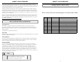
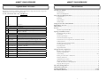
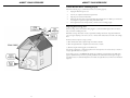
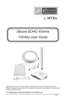
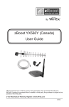
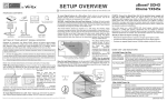
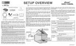
zBoost YX645 User Guide 30 day money back guarantee when you buy directly from Wi-Ex®. If product is purchased from a reseller or third party, you must use their return policy. 1 Year Manufacturer Warranty. Register your zBoost® product at www.Wi-Ex.com DMAN-0041 v2.0910 zBOOST® YX645 USER GUIDE zBOOST® YX645 USER GUIDE About zBoost® from Wi-Ex® Wi-Ex® is the leader in cell phone signal boosters. zBoost® enhances the performance of your cell phone, PDA and wireless data card. Compatibility – Dual Band zBoosts are compatible with 800MHz and 1900MHz regardless of technology- including CDMA and GSM. Patented technologies protect the carrier network. 1-year manufacturer warranty – register your product at www.Wi-Ex.com. zBoost® products have more awards, more sales and more locations than all other signal boosters …COMBINED. FCC Information FCC ID: SO4YX545-PCS-CEL Warning: Changes or modifications to this device not expressly approved by Wi-Ex® could void the user’s authority to operate the equipment. Note: This equipment has been tested and found to comply with the limits for a Class B digital device, pursuant to Part 15 of the FCC Rules. These limits are designed to provide reasonable protection against harmful interference in a residential installation. This equipment generates, uses, and can radiate radio frequency energy and, if not installed and used in accordance with the instructions, may cause harmful interference to radio communications. However, there is no guarantee that interference will not occur in a particular installation. If the equipment does cause harmful interference to radio or television reception, which can be determined by turning the equipment off and on, the user is encouraged to try to correct the interference by one or more of the following measures: • Reorient or relocate the receiving antenna • Increase the separation between the equipment and receiver • Connect the equipment to an outlet on a circuit different from that to which the receiver is connected • Consult the dealer or an experienced radio/TV technician for help This equipment complies with FCC radiation exposure limits set forth for an uncontrolled environment. This transmitter must not be co-located or operating in conjunction with any other antenna or transmitter. In accordance with FCC requirements of human exposure to radiofrequency fields, the radiating element (antenna) shall be installed such that a minimum separation distance of 20cm (8in) is maintained from all persons. Industry Canada Regulations IC ID: 5544A-YX545PCSCEL This Class B digital apparatus meets all requirements of the Canadian Interference Causing Equipment Regulations. Operation is subject to the following two conditions: (1) this device may not cause harmful interference, and (2) this device must accept any interference received, including interference that may cause undesired operation. The term “IC:” before the radio certification number only signifies that Industry Canada technical specifications were met. RF Exposure:The manufacturer’s rated output power of this equipment is for single carrier operation. For situations when multiple carrier signals are present, the rating would have to be reduced by 3.5 dB, especially where the output is re-radiated and can cause interference to adjacent band users. This power reduction is to be by means of input power or gain reduction and not by an attenuator at the output of the device. i zBOOST® YX645 USER GUIDE zBOOST® YX645 USER GUIDE Cet appareillage numérique de la classe [B] répond à toutes les exigences de l’interférence canadienne causant des règlements d’équipement. L’opération est sujette aux deux conditions suivantes: (1) ce dispositif peut ne pas causer l’interférence nocive, et (2) ce dispositif doit accepter n’importe quelle interférence reçue, y compris l’interférence qui peut causer l’opération peu désirée. Le fabricant nominale de la puissance de sortie de ce matériel est simple transporteur. Pour les situations lorsque plusieurs signauxporteurs sont présents, l’évaluation devrait être réduite de 3.5 dB, en particulier lorsque le signal de sortie est ré-émise et peut provoquer des interférences adjacentes à la bande utilisateurs. Ce pouvoir est de la réduction par le biais de la sortie d’alimentation ou la réduction de gain et non par un atténuateur à la sortie du dispositif. Please note: This unit has been approved for use in Canada under RSS 131, however, consent for the use of this device to improve cellular or PCS coverage, must be obtained through your cellular or PCS provider, prior to placing the unit in operation. Please refer to the Industry Canada document CPC 2-1-05, Section 6.1 available or viewable at: http://www.ic.gc.ca/epic/site/smt-gst.nsf/en/sf08942e.html Package Contents: zBoost® YX645 Before you begin, make sure all of the following parts came with your zBoost® YX645. Item Quantity Part # Description 1 1 DMAN-0043 YX645 Setup Overview 2 1 DMAN-0041 YX645 Manual 3 1 APCA-0031 YX645 Base Unit 4 1 CPSP-0009 Base Unit Power Supply, White 5 1 YX031-10W 10’ RG-8X extension coax This manual is copyrighted. All rights reserved. This manual, whole or in part, may not be copied, photocopied, reproduced, translated or reduced to any electronic medium or machine readable form for distribution. This manual whole or in part, may not be modified without prior consent, in writing, from Wireless Extenders. 6 1 YX027-PCS-CEL 6/9 dBi Directional PCS-CEL Indoor Antenna 7 1 YX021-CEL 8 dBi Directional CEL Outdoor Antenna 8 1 YX023-PCS 13 dBi Directional PCS Outdoor Antenna Copyright © 2010 by Wireless Extenders, Inc. 9 1 YX015D Dual Band Outdoor PCS-CEL Signal Combiner Trademarks 10 1 AHDW-0002 Hardware Kit (anchors, feet, screws) Safety and Product Warranty Information Copyright Notice Wireless Extenders, Wi-Ex, the Wi-Ex logo, zBoost, the zBoost logo and Extending Cell Zones are registered trademarks of Wireless Extenders, Inc. Safety Guidelines In accordance with FCC requirements of human exposure to radiofrequency fields, the radiating element (antenna) shall be positioned such that a minimum separation distance of 8 inches (20cm) is maintained between the radiating element and the user and/or general population. Limited Liability In no event shall Wireless Extenders be liable for any direct, indirect, special, punitive, incidental, exemplary or consequential damages, or any damages, whether in an action under contract, negligence, or any other theory, arising out of or in connection with the set up of, use of, inability to use, or performance of the information, services, products, and materials available from this manual. These limitations shall apply notwithstanding any failure of essential purpose of any limited remedy. Because some jurisdictions do not allow limitations on how long an implied warranty last, or the exclusion or limitation of liability for consequential or incidental damages, the above limitations may not apply to you. For full warranty guidelines, see page 16. Note Changes or modifications not expressly approved by Wi-Ex® could void the user’s authority to operate this equipment and/or void the product warranty. ii iii zBOOST® YX645 USER GUIDE zBOOST® YX645 USER GUIDE Optional zBoost® Accessories Table of Contents The following accessories are available to improve signal reception and provide increased coverage in the building. Please see our website for complete selection. YX645-Dual Band To order, call 1-800-871-1612 or visit, www.Wi-Ex.com Part # Description Most Popular Accessories for the YX645: X YX026-CEL Directional receiving Signal Antenna upgrade (11 dBi) X YX050-PCS-CEL Omni-Directional transmitting ceiling-mount Base Unit Antenna (2 dBi PCS / 1 dBi CEL) Other Accessories: X YX012 Outside Grounding Kit X YX014 Outdoor J-pole Antenna Mounting Bracket X YX022-CEL Omni-Directional receiving signal antenna upgrade (6 dBi) X YX024-PCS Directional transmitting Base Unit Antenna upgrade (7 dBi) X YX026-CEL Directional receiving Signal Antenna upgrade (11dBi) X YX028-PCS-CEL Directional transmitting window-mount Base Unit Antenna upgrade (9 dBi PCS / 6 dBi CEL) X YX030-15W 15 ft. Signal Antenna coax extension, low-loss RG-6 X YX030-35W 35 ft. Signal Antenna coax extension cable, low-loss RG-6 X YX030-08W 8” flat window entry cable X YX055-CEL CEL Directional Outdoor Yagi Antenna (15 dBi) X YX699 RF Signal Meter iv About zBoost® from Wi-Ex® .........................................................................................................................i FCC Information .................................................................................................................................... i Industry Canada Regulations .................................................................................................................. i Safety and Product Warranty Information ..................................................................................................ii Copyright Notice ................................................................................................................................... ii Trademarks ............................................................................................................................................ ii Safety Guidelines ................................................................................................................................... ii Limited Liability .................................................................................................................................... ii Package Contents: zBoost® YX645-PCS-CEL............................................................................................ iii Optional zBoost® Accessories .....................................................................................................................iv Table of Content .........................................................................................................................................1 Overview .....................................................................................................................................................2 Why Indoor Signals Can Be Weak ......................................................................................................... 2 Preparing to Install zBoost® Product ...........................................................................................................3 Read Before Installing the YX645 .......................................................................................................... 3 Tools Needed ......................................................................................................................................... 3 Check for Signal Strength ...................................................................................................................... 3 Determine the Needed Coverage Area.................................................................................................... 4 Determine the Location of Signal Antennas and the Indoor Antenna..................................................... 4 Cable Requirements ............................................................................................................................... 4 Grounding the Directional Signal Antennas ........................................................................................... 5 Securing Cable with a Drip Loop ........................................................................................................... 5 Power Requirements .............................................................................................................................. 5 Important Reminders ............................................................................................................................ 5 Setting Up Your zBoost® Signal Booster ......................................................................................................6 Placement of the Signal Antenna............................................................................................................ 6 Mounting of Signal Antennas ................................................................................................................ 6 Antenna Aiming ............................................................................................................................. 7 & 8 Running the Coaxial Cable to the Base Unit .......................................................................................... 8 Mounting the Base Unit......................................................................................................................... 8 Installing the Indoor Antenna ................................................................................................................ 9 Illustration of YX645 setup in home .................................................................................................... 10 Confirm That The zBoost® is Working Properly ................................................................................... 11 Improving The Coverage Area .............................................................................................................. 11 zBoost® Base Unit Light Indicators ...........................................................................................................12 YX645 Technical Specifications.................................................................................................................13 Frequently Asked Questions ............................................................................................................14 & 15 zBoost® Warranty Information .........................................................................................................16 & 17 1 zBOOST® YX645 USER GUIDE zBOOST® YX645 USER GUIDE Overview Thank you for choosing zBoost®. You will now be able to use cell phones INSIDE the building. Gone are the days when one had to go to the window upstairs or walk outside to use a cell phone. Like a skylight that brings sunlight into a home, zBoost® transports and amplifies the outdoor cellular signals into the building. By following the easy instructions in this user guide, you will be Extending Cell Zones™ into the building. Preparing to Install zBoost® Read First Before Installing the YX645 Before unpacking this box, verify that your phone operates on the frequency band supported by this product. Note: The YX645 is not compatible with iDEN, Nextel, SMR or ESMR frequency services. Why Indoor Signals Can Be Weak There are several obstacles that can contribute to the poor reception you receive in a building: 1. Location of the Cell Phone Tower in Relation to the building While cell phone providers have tried to place cell phone towers to provide the best overall coverage, local ordinances and terrain features can impose restrictions on where these towers can be placed, thus, limiting the signal strength available at your location. 2. Obstructions Caused by Buildings, Terrain and Trees Cell phone signals can be completely blocked or reflected by buildings, walls, trees, hills and other terrain features resulting in low signal strength. 3. Energy Efficient Windows These new windows can also affect signal penetration into the house Tools Needed The following tools are needed to set up zBoost®: • #2 Philips screwdriver • Cellular phone operating in the band supported by your zBoost® unit • Drill (may be required for outdoor or attic antenna placement) Check for Signal Strength Before placing a zBoost® in a home, make sure that you can place calls on the outside of the building, in the attic, at roof level or wherever you plan to place the Signal Antenna. zBoost® can only bring signal into the building when signal reaches the Signal Antenna. If there is no signal, the zBoost® will not work for you. Using your cell phone, place a call from an outdoor location to confirm that enough signal is present to complete the call. If a weak signal is available at ground level, check the signal strength in the attic or at roof level location where the signal will likely be stronger and where the Signal Antenna can be placed for best performance. If you can reliably make and receive calls outside the building, then zBoost® can bring the signal into your home. If only one signal bar is displayed on your cell phone outside, indoor coverage will be limited to one to two rooms. We recommend placing the Signal Antenna outside and/or purchasing a Wi-Ex® upgrade Signal Antenna for increased coverage (see page iv). The YX699 Signal Meter (available separately) provides signal strength information. It can be used with its supplied whip antenna to find the best location for placement of the Signal Antennas by identifying the area of strongest signal. It can also be used to identify peak antenna alignment when connected directly via provided cable. Contact Wi-Ex to obtain a YX699 Signal Meter. Note Cell phone signal bars are approximate and vary from phone to phone. The number of bars can fluctuate widely, depending on the location of the phone, the position or angle of the phone, weather, etc. Most cell phone signal meters update every 6 to 10 seconds. An increase of only one bar typically indicates a 4x to 10x signal increase THE BEST INDICATOR OF COVERAGE AREA IS THE ABILITY TO RELIABLY PLACE AND RECEIVE CALLS 2 3 zBOOST® YX645 USER GUIDE Determine the Needed Coverage Area zBOOST® YX645 USER GUIDE Grounding the Directional Signal Antennas Identify the location in your home/office where you need signal coverage the most. The zBoost® YX645 can cover up to 10,000 square feet (coverage varies based on outdoor signal level, building construction, placement of antennas, and general installation care). Walls, ceilings or floors will reduce the coverage area. The Directional Signal Antenna assembly must be properly grounded when it is installed outdoors. This will help protect the customer’s property and the Base Unit against lightning strikes during a lightning storm. The installation must be in accordance with Article 810 of the National Electric Code (NEC). A listed antenna discharge unit must be provided for the lead-in coaxial cable per NEC article 8.10.20 or the shield of the coaxial cable must be permanently and effectively grounded in accordance with NEC article 8.10.21.. Securing Cable with a Drip Loop When you install the Directional Signal Antennas, create a drip loop with the coaxial cable at the point where the cable enters the building through an outside wall. This can be done by twisting and securing the cable into a loop (no less than 4” across) near the entry point. This will help prevent moisture from gathering at entry point and leaking into the building. Exterior Wall Determine the Location of Signal Antennas and the Indoor Antenna It is recommended that the Signal Antennas and Indoor Antenna have over 15 feet of vertical and 20 feet of horizontal separation. Coax Cable If the antennas are too close together, the light on the Base Unit will flash red, indicating a problem see the Light Indicators section (Page 12). To capture the best signal, place the Signal Antenna as high as possible and position it vertically, keeping it at it at least 2 feet away from any metal. Place the Signal Antennas as high as possible to capture the best signal. See page 6, Installing Your zBoost® Product, for additional information. Power Requirements Note: Coverage and Signal Antennas should be pointed AWAY from each other. The Base Unit can be plugged into a standard 2-prong 110 VAC receptacle using the included power supply. The power supply consumes less than 10W (less than 0.2A). Cable Requirements You must use RG-6 coaxial cable and F connectors which are rated for outdoor satellite TV use and can be found at many home improvement and electronic stores. Coaxial cable is not provided with the YX645. After installing the Signal Antennas, run coaxial cable between antenna assembly and Base Unit. The recommended maximum cable length run for RG-6 is 60’ and 100’ for RG-11. It is highly recommended that you refrain from securing your cable, drilling any holes, etc. until you complete and test the installation of the Base Unit.. Important Reminders: • The required coaxial cable has NOT been provoided. • An exterior mounting mast has not been provided. Using at least 1.5” PVC pipe or a J-pole (available from Wi-Ex, part YX014) is suggested should one be needed.. Caution: Before drilling any holes into a wall to run your cable, make sure you know where existing electrical wiring is located. Drilling into live electrical wiring could cause and electrical shock and sever the wire. Note Note Avoid placing the Signal Antenna near metal such as wiring, A/C ducts, metal siding, truss plates, etc. When connecting the cable to the antenna, run the cable straight down from the antenna. Avoid draping the coax near the antenna. 4 The zBoost® YX645 base unit MUST only be used with the provided power adaptor. Use of other power adaptors will void the warranty and may damage the unit. Use of other equipment is not FCC approved. 5 zBOOST® YX645 USER GUIDE Installing Your zBoost® Signal Booster Placement of the Signal Antennas Choosing the best location for installation of the Signal Antenna provides the best performance and the largest area of improved signal. Determine the location which provides the strongest signal using the signal strength indicator on your cell phone. Find the location which provides the most bars of signal strength and locate the Signal Antenna at that location. This location will be typically found on the roof. The YX699 Signal Meter (available separately) provides signal strength information. It can be used with its supplied whip antenna to identify the area of strongest signal for placement of the Signal Antennas. It can also be connected directly to the Signal Antennas to identify peak antenna alignment. Contact Wi-Ex to obtain a YX699 Signal Meter. zBOOST® YX645 USER GUIDE NOTE: The zBoost® YX645 requires at least 15 feet of vertical separation between the Base Unit and the Signal Antennas. Generally, increasing this distance (up to 40 feet) will increase the performance and decreasing the distance will limit zBoost® performance. (If 15 feet of separation is not possible, you may try our new METRO model, which was designed for lofts and urban dwellings and requires no vertical separation.) Keep the Base Unit off the floor and at least 2 feet away from other cords, metal objects or other wireless devices such as wireless routers or wireless access points. The zBoost® performs best when there are no obstructions between the zBoost® Base Unit and your mobile device. Upon initial power up, a solid GREEN light should appear indicating normal conditions. If a RED light appears, adjustments may be needed to optimize performance. If you find the increased signal coverage is acceptable, however, no additional adjustments are needed. See Light Indicator section (Page 12) for more information. Antenna Aiming To get the maximum benefit, , you will want to take special care to make sure you point the antennas in the direction of the best signal for your wireless service provider. You may wish to use a YX699 RF signal meter to help during this process. Mounting Signal Antennas 1. When you have determined the location of the strongest signal, install the antennas to a mast or j-pole (Not provided- OutdoorJ-pole Antenna Mounting Bracket, YX014). Loosely tighten the antennas to the mast to allow the antennas to be reoriented for strongest signal. 2. Connect the provided coax from the panel antenna to the connection on the Signal Combiner marked CEL. Connect the supplied 18” coaxial jumper from the Panel antenna to the other Signal Combiner port marked PCS. After installing the Signal Antennas to a mast or pole, connect them to the Signal Combiner (as pictured below). Make sure to connect PCS and CEL outputs to the matching antenna. Connecting the antenna to the wrong Signal Combiner port will not produce an improved signal. Then, connect either RG6 or RG11 (not included) coax cable to the opposite end of the Signal Combiner going to the Base Unit. Signal Combiner Note: The Outdoor Signal Antenna must be pointed AWAY from the Indoor Antenna. Additionally, it should be mounted of the roof edge, pointed away from the building. If you do not know which direction the best signal is coming from, once the unit is installed, rotate the Signal Antennas in 90 degree increments while measuring the results inside the desired coverage area. In most cases both Signal Antennas should be aimed in the same direction. 1. Using a phone operating in the Cellular band, place the cell phone on a non-metal surface about 6-8 feet from the Base Unit. 2. Turn the signal booster on and wait 30 seconds. Note the number of signal bars displayed on your cell phone. For best results, you want to place your phone where the phone’s signal meter displays in the middle of the signal meter range or less so that it can indicate as you rotate the Signal Antenna to the optimum direction. If it is reading too high, move the phone farther from the Indoor Antenna. 3. Record the number of signal bars or dBm________(A) on your cell phone. You can use our YX699 RF Signal Meter or an application on a smart phone to get the dBm. Leave the phone in exactly the same place and pointing in the same direction for the following steps. Note the direction of the CEL Panel Signal Antenna starting position ________________. 4. Rotate the CEL Panel Signal Antenna 90 degrees and then record the phone signal bars _________ (B). 5. Continue to rotate the antenna another 90 degrees in the same direction and record the phone signal bars _________(C). 6. Again, rotate the antenna another 90 degrees in the same direction and again record the phone signal bars _________(D). 7. If you desire to optimize further, then look for the two highest signal bar readings above and move the antenna between these two points to find the highest signal bars reading. 8. Look for the highest reading above. Set the antenna to that position and tighten the antenna to the mast of your choosing. We suggest PVC pipe that is at least 1.5” or J-Pole (part # YX014, not included). 9. Using a phone operating in the Cellular band, place the cell phone on a non-metal surface about 6-8 feet from the Base Unit. 10. Turn the signal booster on and wait 30 seconds. Note the number of signal bars displayed on your cell phone. For best results, you want to place your phone where the phone’s signal meter displays in the middle of the signal meter range or less so that it can indicate as you rotate the Signal Antenna to the optimum direction. If it is reading too high, you may want to move the phone farther from the Indoor Antenna so that you are able to see the change when you reorient the Signal Antenna. 7 Outdoor Signal Antenna Note Avoid placing the Signal Antenna near metal such as wiring, A/C ducts, metal siding, truss plates, etc. When connecting the cable to the antenna, run the cable straight down from the antenna. Avoid draping the coax near the antenna. 6 zBOOST® YX645 USER GUIDE 11. Record the number of signal bars ________(A) on your cell phone. Leave the phone in exactly the same place and pointing in the same direction for the following steps. Note the direction of the Panel antenna starting position ________________. 12. Rotate the Panel antenna mast 90 degrees and then record the phone signal bars _________(B). 13. Continue to rotate the antenna mast another 90 degrees in the same direction and record the phone signal bars _________(C). 14. Again, rotate the antenna mast another 90 degrees in the same direction and again record the phone signal bars _________(D). 15. If you desire to optimize further, then look for the two highest signal bar readings above and move the antenna between these two points to find the highest signal bars reading. 16. Look for the highest reading above. Set the antenna to that position and tighten the antenna to the mast. zBOOST® YX645 USER GUIDE Installing the Indoor Antenna The interior panel antenna is connected to the base unit using the provided 10’ RG-8X coax. It should be mounted on a wall facing the direction where increased coverage is desired.. The majority of the time a cell tower will hold more than 1 frequecy band and/or service provider, so aim the second Signal Antenna in the same direction. You may need to use a PCS phone. To aim each antenna for maximum signal, you may need more than one cell phone, one operating in the Cellular band (typically AT&T, Verizon or Alltel) and one operating in the PCS band (typically Sprint, T-Mobile, Metro PCS, Cricket). Note: A 1 dBm increase is 25% gain in signal strength. Running the Coaxial Cable to the Base Unit Coaxial cable is not provided with the YX645. After installing the Signal Antennas and connecting them you will need to run coaxial cable to the location where you plan to install the Base Unit. The recommended maximum cable length run for RG-6 is 60’ and 100’ for RG-11. It is highly recommended that you refrain from securing your cable, drilling any holes, etc. until you complete and test the installation of the Base Unit. For example, if you plan to use the Base Unit in the living room of a two-story home, first run the cable from the attic down the stairs to the living room. After the Base Unit is installed and successfully working, find a more direct and permanent route for the cable (e.g., dropping it through the ceiling of a nearby closet). Wall Mounting the Base Unit The Base Unit can also be easily mounted on a wall. The Base Unit should be a minimum distance of 4-5 feet off from the floor so there is clearance for the Indoor Antenna extension. Perform the following steps to mount the Base Unit on a wall: 1. Remove the mounting bracket from the Base Unit by slightly spreading the tabs on the orange mounting bracket. 2. Fasten the mounting bracket to the wall using the self-tapping wall/ceiling anchors. 3. Snap the Base Unit into the mounting bracket. Base Unit with Indoor Antenna Note Before drilling any holes into a wall to run your cable, make sure you know where existing electrical wiring is located. Drilling into live electrical wiring could cause an electrical shock and sever the wire. 8 9 zBOOST® YX645 USER GUIDE zBOOST® YX645 USER GUIDE Confirm That Your zBoost® is Working Properly Perform the following steps to confirm that the unit is now working properly: 1. Unplug the Base Unit power cord. 2. Turn on your cell phone and check the signal meter. 3. Plug the power cord into the Base Unit. 4. Hold your cell phone about 5 feet from the Base Unit and then turn it on. Wait up to 1 minute for the cell phone to register the signal coming from the Base Unit. 5. If the signal meter shows an improvement, your zBoost unit is working properly. Improving Your Coverage Area With everything connected and the Base Unit plugged in, you should walk throughout the room and see that you are able to reliably place calls. Remember, coverage varies based on outdoor signal level, building construction, and general installation care. Coverage in adjoining rooms (next to, above, or below) will be reduced due to the walls or the ceiling/ floor. Should you desire to improve coverage, you may: 1.) Move the Base Unit and/or adjust the angle of the Indoor Antenna. 2.) Move the Signal Antenna to a higher location in the attic or outside. 3.) Purchase a Signal Antenna upgrade at www.Wi-Ex.com. Note: Using a signal meter or an antenna application on a smart phone is a more accurate way to measure a stronger signal than the bars on a phone. Upon initial power up, a solid GREEN LED should appear indicating normal conditions. If a RED light appears, adjustments may be needed to optimize performance. If you find the increased signal coverage is acceptable, however, no additional adjustments are needed. See Light Indicator section for more information (Page 12). 10 11 zBOOST® YX645 USER GUIDE zBOOST® YX645 USER GUIDE zBoost® Base Unit Light Indicators Technical Specifications At Initial Power Up Only Solid GREEN Normal condition at power up. Slowly Alternating RED and GREEN zBoost® is working, but at reduced performance and coverage due to “nonideal” setup. Solution: Increase the distance betweenSignal Antenna and Base Unit to achieve maximum performance and coverage. Indicates insufficient distance between the antenna and the amplifier. The amplifier is operating at significantly reduced coverage. Fast Flashing RED Solid RED PCS Frequency CEL Frequency 1850 - 1990 MHz 824 - 894 MHz System Gain 75 dB 67 dB Band Supported ALL: A,D,B,E,F & C ALL: A,B, A’ & B’ Antenna Signal 13 dBi Panel; F-type female 8 dBi Panel; F-type female Antenna- Base Unit 9 dBi Panel; TNC male 6 dBi Panel; TNC male Cable Loss 3000 MHz RG-6, approx. 1 dB/10 ft. 3000 MHz RG-6, approx. 0.6 dB/10 ft. Frequency Both PCS and CEL Frequencies Network Format CDMA, GSM, TDMA, AMPS, GPRS, EDGE, EVDO, HSPA, 3G Solution: Increase space between base unit and antenna. Base Unit RF Connectors F-type female and TNC female Wall Supply Unit 100-240 VAC 50 Hz-60Hz System is receiving signals from either the mobile device or the base station transceiver which are too strong for proper operation. Power Consumption 3W standby; 7W max signal - 2.0A Max Solutions: Move away from receiving antenna with your cell phone. Move antenna away from other devices.. The amplifier is disabled. Fast Alternating RED and GREEN followed by no light YX645 PCS-CEL Technical Specifications System Certifications UL, FCC Parts 15 & 24 (PCS), FCC Parts 15 & 22 (CEL), Industry Canada Base Unit Size and Weight 5” x 7” x 1.375” - 12 oz. Base Unit and Power Supply Indoor Use Only, 5° to 40° C (40° to 105° F) Coverage (open areas) 4-5 signal bars at the roof antenna; 110’ radius at 100° width; 3-4 signal bars inside; over 10,000 sq. ft. Handles all PCS or CEL protocols and included multiple patented and patent pending technologies to provide lowcost coverage while continually adapting to signal to prevent interference and remain transparent to the wireless network. Provides an indicator if the antennas are positioned improperly, but will NOT suffer damage of interfere with the Carrier Network. Solution: Unplug and start over. After Initial Power Up Solid GREEN Normal condition. Solid RED System is receiving signals from either the mobile device or the base station transceiver which are too strong for proper operation. This product is covered by patent US 7,706,744. Other U.S. and foreign patents pending. Solution: Please unplug your system. Re-orient your Signal Antenna and/or Base Unit to reduce the excessive signal source. Plug your system back in. If still solid red, call customer support 1-800-871-1612. 12 13 zBOOST® YX645 USER GUIDE zBOOST® YX645 USER GUIDE Frequently Asked Questions Frequently Asked Questions What can I expect my cell phone signal range and strength to be inside my home or office? Where should I put my Wi-Ex base unit to get the best coverage? The closer you are to the base, the stronger the signal. This will vary with different conditions. Some of the conditions that will affect the improved coverage area are signal strength outdoors, the type of building materials in the home, the placement of the unit and the antenna’s proximity to cellular towers. You should install your base unit where you need coverage the most. The Wi-Ex base unit is the component that amplifies the signal inside. The coverage is improved in a circular manner from the base unit. The farther you are away from the base unit, the weaker the signal. The base could be placed in the family room, the basement, an office, a bedroom, a home office or a central location. You can expect that your indoor coverage will be improved. You will be able to make calls where you couldn’t before. The degree of improvement will depend upon many factors. The intent of zBoost® products are to bring outside coverage inside. Just as the signal bars move up and down when outside, the boosted signal will fluctuate in a similar fashion. Is a cellular phone signal booster the same as a wireless router; will it help my WiFi signal? The Wi-Ex® unit will not help your WiFi service. This unit is designed to work with wireless PCS and Cellular phones and devices. The WIFI in your home or office operates on a different frequency. Is your product available for international use? Yes, we have products that work on European frequencies. Our zBoost® YX520-I– Dual band works on 900MHz and 1800Mhz. We also sell zBoost® ONE YX400-U for UMTS/HSPA devices on the 2100MHz Frequency, a frequency used for voice and data overseas. Why isn’t my cell phone indicating more signal with more bars? Note: if you install the Signal Antenna too close to the Base Unit, the system will shut down (red light will blink). This is a normal condition for this scenario. It just means that you need to ensure that you have sufficient distance between the 2 antennas; otherwise, it will detect feedback or noise and will automatically shut down. Where is the best place to put my Wi-Ex Signal Antenna? The Wi-Ex signal antenna should be placed at the highest point in your house in order to “catch” the strongest signal. This location could be in the attic or on the roof. The placement of the Signal Antenna is very important. It is best to place this in an un-obstructed area. If you install it outside, place it above the roof line. Or, this antenna can be placed in the area around your home that has the greatest signal strength. Note: if you install the Signal Antenna too close to the Base Unit, the system will shut down (red light will appear). This is a normal condition for this scenario. It just means that you need to ensure that you have proper isolation between the 2 antennas; otherwise, it will detect feedback or noise and will automatically shut down. My light is continually blinking You may not always observe more bars that gain on your signal meter because of the signal spreading out from the antenna. If your phone has a dB meter, 3dB is a significant increase of 2x, 6dB is 4x, and 10dB is 10x. On a four bar phone, one "bar" equals about 10dB. There are several reason that the zBoost® light could be blinking. Please see the Light Indicator section on Page 12 for specific answers. The increase in signal you will see depends upon: Does the zBoost® work on all 3G data? • The level of signal at the Signal antenna (outdoor) • The care of the antenna placement (two feet away from metal, adequate antenna separation [15 feet recommended]) • The signal already present inside (related to building losses) • The distance of your phone/device from the Base Unit (signal spreads or diminishes rapidly with distance.) No, it only works on data that is on 1900 and 800 mHz frequency like iPhones, but not on smartphones that use 3G on 2100 mHz frequencies. There are usually several cell phones in use at one time in my home, will your product boost all of our signals simultaneously? The zBoost® YX645 is designed to cover multiple signals simultaneously and will allow multiple users to operate at the same time. Does the zBoost® work if you have no bars? No, if no signal is present outdoors zBoost® producs will not work for you. Also, keep in mind if your best signal is 1 bar at the Signal Antenna, your coverage will be limited to one or two rooms. You could improve that with an upgraded antenna. (See page iv). 14 15 zBOOST® YX645 USER GUIDE Warranty Information Limited 1 Year Warranty Register your product at www.Wi-Ex.com Wi-Ex® warrants every Wi-Ex® product to be free from defects in material and workmanship under normal use for the warranty period of one year. Who Is Covered? zBOOST® YX645 USER GUIDE Make sure you keep… Please keep your sales receipt or other document showing proof of purchase. Attach it to this User Guide and keep both nearby. Also, keep the original box and packing material in case you need to return your product. Before requesting repair service… If red light is on, system is receiving signals from either the mobile device or the base station transceiver which are too strong for proper operation. Please unplug your system. Re-orient your Signal Antenna and/or Base Unit to reduce the excessive signal source. Plug your system back in. If still solid red, call customer support 1-800-8711612. To get warranty service… You must have proof of purchase to receive warranty service. A sales receipt or other documentation showing the product purchased and the purchase date is considered proof of purchase. This limited warranty extends only to the original consumer purchaser or any person receiving the product as a gift from the original consumer purchaser and to no other purchaser or transferee. This warranty does NOT extend to commercial users. What is Covered? Warranty coverage begins the day you purchase the product. For one year from the original date, the Wi-Ex® Cell Phone Signal Booster will be repaired or replaced with a new, repaired, refurbished or comparable product (whichever is deemed necessary by Wi-Ex® ) if it becomes defective or inoperative. The exchange will be made without charge to you for parts and labor. You will be responsible for the cost of shipping to the location designated by Wi-Ex®. All products, including replacement products, are covered only for the original warranty period. When the warranty on the original product expires, the warranty on the replacement product also expires. Warranty service will be provided by Wi-Ex®. If you believe you need service for your unit, contact Wi-Ex® at 1-800-871-1612 or [email protected]. A representative will go through a diagnostic checklist with you. If it is determined that the product needs to be returned for service or exchanged, you will receive a return merchandise authorization (RMA) number. The representative will give you complete shipping details. Do not return products to Wi-Ex® without a Return Authorization Number (RMA). To get out of warranty service… To obtain out of warranty service, contact Wi-Ex® at 1-800-871-1612 or [email protected] for information on the possibility of any costs for repair or replacement of out-of-warranty products. Reminder Record the model and serial number found on the product below: What is Excluded? Model #: __________________________________ Your warranty does NOT cover: Serial #: ___________________________________ • Labor charges for set up of the unit. • Product replacement because of misuse, accident, lightning damage, unauthorized repair or other cause not within the control of Wi-Ex®. • Incidental or consequential damages resulting from the product. Some states do not allow the exclusion of incidental or consequential damages, so the above exclusion may not apply to you. • Any modifications or other changes to the product, including but not limited to software or hardware modifications in any way other than as expressly authorized by Wi-Ex® will void this limited warranty. • Product that has been modified or adapted to enable it to operate in any country other than the country for which it was designed, manufactured, approved and/or authorized, or repair of products damaged by these modifications. 16 Purchase Date: ____________________________ 17