1
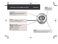
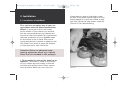
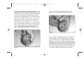
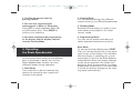
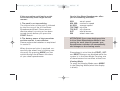
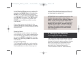
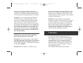
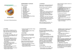
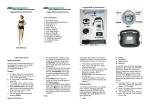
Microsport_Basic_11/02
11.11.2002
15:16 Uhr
Seite 41
®
FCC-ID: OWUOK622-7
The devices comply with Part 15 of
the FCC rules. Operation is subject to
the following two conditions:
This device may not cause harmful
interferences and this device must
accept any interference received,
including interference that may
cause undesired operation.
MICROSPORT
In-Line Skate
Speedometer
BASIC
Microsport_Basic_11/02
11.11.2002
15:16 Uhr
Seite 43
In-Line Skate
Speedometer BASIC
Operating Instructions
Thank you very much for choosing the
MICROSPORT In-Line Skate Speedometer.
This Speedometer is recommended because of the easy installation and handling as well as its outstanding accuracy.
1.
Components of the In-Line Skate
Speedometer
2.
The keys of the display and their
functions
Don’t expose your Speedometer to direct
sunlight for a long period and protect the
display from extreme cold and hot temperatures. Handle your display carefully
and keep it in a clean and dry state.
3. Installation
3.1. Installation of the Wheel
3.2. Display and Wheel Size
4.
Operating the In-Line Skate
Speedometer
5. Changing of the Batteries
5.1. Changing the display battery
5.2. Changing the battery of the computer
puck
6.
Trouble Shooting
7.
Remarks
8.
Warranty
Before you start using your Speedometer
please read this operating manual carefully. The actual installation procedure will
not take you longer than 10 minutes.
Attention:
1. The Skate Speedometer contains some
small components which can be swallowed and can cause death by suffocation.
2. Always check the equipment before
skating. Check the bearings and the
fitting of the axle to avoid blocking or
loosening of a wheel.
Microsport_Basic_11/02
11.11.2002
3. Skating accidents can always happen,
even to experienced skaters. To avoid
serious damage always wear the complete protective gear.
4. Skating needs the full attention of the
skater, so don’t let the Skate Speedometer disturb you from the traffic
around you.
1. Components of the In-Line Skate
Speedometer
Before you start please check the completeness of your Speedometer package.
Your Speedometer consists of:
1. A puck, housing the skate computer.
The puck is approximately 1 cm high
and has a 5 cm diameter
2. A skate wheel with an internal magnet
3. A watch like Display
15:16 Uhr
Seite 45
B. One spacer for skates with 8 mm axle
diameter.
C. One spacer for skates with 6,4 mm axle
diameter.
D.One distance ring.
And this instruction manual.
The different components of your
speedometer are shown in picture 1.
A)
B)
C)
D)
Outer spacer
Ring spacer
Cylindrical spacer
Distance ring
A B
C DA
Wheel
Display
Puck
The package contains five different spacers:
A.Two outer spacers to fit the In-Line Skate
Speedometer Wheel in wider frames.
1
Picture 1
2
3
Content of the packaging
Microsport_Basic_11/02
11.11.2002
15:16 Uhr
2. The keys of the display and their
Seite 47
functions
START
START activates
the Data-Mode.
SET/DOWN
SET activates the Programming-Mode.
DOWN - the value programmed is
reduced by one
MODE
By pressing MODE the following
functions can be displayed:
SPD – actual speed
MX SPD – maximum speed
AV SPD – average speed
TRP TIME – trip time
TRP DST – trip distance
DST – total distance
PM – wheel ware rate
RESET
RESET erases all data except the total
distance and the wheel wear rate
Microsport_Basic_11/02
11.11.2002
3. Installation
3.1. Installation of the Wheel
15:16 Uhr
Seite 49
screw keep an eye on the other screw
as well. If the other screw begins to turn
freely please fix it with you hand or another tool. Store the two screws carefully
(Picture 2) for reassembling.
First you have to replace one of your current wheels with the Skate Speedometer
Wheel. In principal it does not matter
which wheel of your skates you replace,
but we recommend that you choose the
second or the third wheel. This guarantees
the best protection of your Speedometer
by the frame of your skate. Also we recommend that you replace a wheel on the
left skate if you want to wear the display
on the right wrist and vice versa.
Attention: Please use adequate equipment to replace the wheel, e.g. a special
Skate-Tool (not included in this package).
1. Disassemble the axle of the wheel to be
replaced. The wheel is fixed to the frame
of your skates by two screws to the left
and the right of the frame. These screws
form the axle. While you turn out one
Picture 2
Microsport_Basic_11/02
11.11.2002
15:16 Uhr
2. Extract the bearings of the wheel. In the
wheel you have disassembled you find two
bearings and one spacer in the middle. You
now have to take these bearings and the
spacer out of the wheel. This is most easily
done with a special skate tool. If you don’t
have such a tool you can also use the cylindrical spacer (C in picture 1) in combination with a small screwdriver. If your skate
uses a cylindrical spacer you can push out
the first bearing by placing the cylindrical
In-Line Skate Speedometer Spacer C on
top of the original spacer (Picture 3) and
Seite 51
press. The second bearing can then be
pushed out from the inside (Picture 4).
Picture 4
Picture 3
If your skate is operating with ring spacers
(B in picture 1) put the screwdriver through
the cylindrical In-Line Skate Speedometer
Spacer C and insert it nearly half way into
the wheel hole for the axle. By bending the
screwdriver to the side you can extract the
first bearing. Again the second bearing can
then be pushed out from the inside without
a problem. Store the bearings carefully.
Microsport_Basic_11/02
11.11.2002
15:16 Uhr
Seite 53
3. Install the first of the bearings into the
In-Line Skate Speedometer Wheel. Push
one bearing with your fingers into the hole
of the Skate Speedometer Wheel (Picture 5).
Picture 5
Picture 6
4. Place the correct spacer into the In-Line
Skate Speedometer Wheel. Decide which
of the In-Line Skate Speedometer Spacers
you need. Principally if your original spacer
looks cylindrical you need the cylindrical
spacer. If your original spacer is a 1 cm thick
ring you need the 3 mm ring spacer. Now
place the spacer into the In-Line Skate
Speedometer Wheel (Pictures 6+7).
Picture 7
Microsport_Basic_11/02
11.11.2002
5. Press the second bearing into the
In-Line Skate Speedometer Wheel. The
Skate Speedometer Spacer is now fixed
between the two bearings (Picture 8).
15:16 Uhr
Seite 55
6. Place the distance ring D (smallest
of the included rings) on the bearing
on the inner side of the In-Line Skate
Speedometer Wheel (Picture 9).
Picture 9
Picture 8
Use a screwdriver to fix a ring spacer in
the centre of the hole.
The inner side can be recognized by the
significant hole to house the computer
puck 1. The distance ring prevents the
wheel and the puck from touching and
grinding against each other.
Microsport_Basic_11/02
11.11.2002
7. Put the Computer Puck 1 into the InLine Skate Speedometer Wheel. Please
note, that the battery in the transparent
puck case should show on to the outside
(Picture 10).
15:16 Uhr
Seite 57
8. Stick the long axle screw through the
frame and the In-Line Skate Speedometer
Wheel and fix it with the second, smaller
screw from the other side of the frame
(Picture 11).
Picture 10
The wheel is now prepared for reassembly
into your skate. Put the complete wheel
back into the frame.
Picture 11
Microsport_Basic_11/02
11.11.2002
Attention: If the wheel moves after tightening of the screws in the direction of the
axle, unscrew the axle one more time and
place one or two of the Outer Spacers A
in front of the puck and behind the wheel
to cover the distance (Picture 12).
15:16 Uhr
Seite 59
9. Check that the Puck 1 does not turn
with the wheel but keeps its fixed position while the wheel is spinning freely.
Attention: After a successful installation
only the In-Line Skate Speedometer
Wheel is rotating. The electronic puck will
be fixed and should not turn.
You have completed the installation of the
wheel now. You do not need any technical
skills for the further steps. In just two
minutes you can start your first trip.
3.2. Display and Wheel Size
Picture 12
The axle can now be put back into your
skate.
The bracelet of the In-Line Skate Speedometer Display is equipped with an elastic
part under the actual watchcase which
allows you to lengthen the bracelet. You
can therefore decide whether to wear the
display directly on the wrist or over the
recommended wrist pads.
Microsport_Basic_11/02
11.11.2002
15:16 Uhr
Seite 61
The In-Line Skate Speedometer is equipped
with an automatic wear out function. The
computer takes into account the reduction
of the wheel perimeter over time. This
guarantees the accuracy of the measurement even if the wheels are already used.
Generally you can calculate the perimeter
of a wheel from the diameter (which is
usually written on the wheel) with the
following formula:
To determine the perimeter of new wheels
use the following list to help you to find
the perimeter of your wheel.
To use the In-Line Skate Speedometer
with worn wheels:
You can easily use the In-Line Skate Speedometer with a used set of other skate wheels.
Most skate brands allow the “rockering”
of the skate wheels. This feature it meant
to assemble wheels of different sizes into
one frame. You can determine the ability
of your skates by dismantling one wheel.
When taking out the axle you can see a
small plastic or metal part called “washer”
with the hole for the axle. This hole is not
in the centre of the washer so it depends
on the installation of the washer at which
height the axle is built into the frame.
Ø 76 mm <=> PM 239 mm
Ø 78 mm <=> PM 245 mm
Ø 80 mm <=> PM 251 mm
Attention: The perimeter programmed into
the display always has to correspond to the
In-Line Skate Speedometer Wheel (the
wheel size is printed on the packaging). The
display in the packaging is preset to a 239
mm perimeter corresponding to a 76 mm
diameter wheel. If you have bought your
speedometer with a different wheel you
have to adjust the perimeter in the Programming-Mode before you start skating.
Perimeter = Diameter x 3,14
If your In-Line Skate Speedometer Wheel
is bigger than the others you will have to
built in the axle closer to the boot. If your
Skate Speedometer Wheel is smaller, the
axle should be closer to the ground.
Microsport_Basic_11/02
11.11.2002
If “rockering“ is not possible with your
skates please use the next larger size of
the In-Line Skate Speedometer Wheel. The
exposure of this wheel will soon be worn
out by the higher pressure on this wheel.
The bigger size of the wheel does not
effect the accuracy of the measurement.
Pay attention that you always program the
perimeter of the In-Line Skate Speedometer Wheel in the display and not the
perimeter of your other wheels.
15:16 Uhr
Seite 63
Attention!
Measuring the actual perimeter of the
wheel: To measure the actual perimeter
of your wheel, make a dot on the In-Line
Skate Speedometer Wheel. Then roll your
skate over a piece of paper and mark the
places when the dot is closest to the
paper at least two times, the distance
between the two marks is the required
perimeter in [mm].
Programming the Display:
Adjusting the wear out function:
The built in wear out function is based
on the statistical normal use of skates.
The real perimeter reduction may differ
individually due to the conditions of the
ground usually skated on as well as the
weight and technique of the skater. If you
get the feeling that the displayed perimeter differs from the real perimeter, you
should reprogram the watch with the
actual value to guarantee the precision
of the measurement.
1. Setting the perimeter of the wheel:
To start the programming mode of the
display press MODE followed by the SETbutton. On the display the PM (perimeter)
symbol appears.
The preset perimeter is 239 mm, which
is equivalent to a 76 mm diameter wheel.
The range for the allowed perimeters
varies from 210 to 251. Press DOWN until
the correct value is reached, i.e. 251 for
an 80 mm wheel.
Microsport_Basic_11/02
11.11.2002
2. Confirm the correct value by
pressing MODE.
15:16 Uhr
Seite 65
2. Viewing Mode
You can browse through the different
stored values of your Skate Speedometer.
3. You can now chose between
measurement in Miles or Kilometres:
Press SET to switch between Miles (M)
and Kilometres (km). Press MODE to
confirm your selection
3. Sleeping Mode
Switches off the display in order to minimize battery consumption. All values
remain stored.
4. You have completed the programming
of the display and the display switches
into the Viewing-Mode.
4. Programming Mode
You can set the wheel perimeter and
select between kilometres and miles.
4. Operating
the Skate Speedometer
In this section the function of the different
keys is explained in detail. Your In-Line
Skate Speedometer display uses four
different modes during operation:
1. Data Mode
This mode has to be activated during
skating for recording your speed and
distance information.
Data Mode
To activate the Data-Mode press START.
First you see the wheel icon in the upper
right corner of the display. This indicates
that the display is searching for a puck
transmitter (in the In-Line Skate Speedometer Wheel). When the display changes
to the actual speed and the wheel icon
begins to blink, the connection has been
established successfully. If no transmitter
is found the display changes to the viewing mode automatically.
Microsport_Basic_11/02
11.11.2002
If the connection could not be established correctly there might be two
reasons:
1. The puck is not transmitting.
The transmission of the puck is initiated
by the first turn of the In-Line Skate
Speedometer Wheel. Please ensure
that the wheel is turning or has been
turned shortly before you press the
START-Button.
2. The battery power of the transmitter
and the receiver is not sufficient.
Please replace the batteries as explained
in section 5.
When the transmission is received successfully the wheel icon is blinking continuously. By pressing MODE you can
switch through the different functions
of your skate speedometer.
15:16 Uhr
Seite 67
Your In-Line Skate Speedometer offers
you the following functions:
SPD
MX SPD
AV SPD
TRP TIME
TRP DST
DST
PM
actual speed
maximum speed
average speed
trip time
trip distance
total distance
wheel wear rate
ATTENTION! If you stop skating and the
In-Line Skate Speedometer Wheel is not
turning for more than 60 seconds your
Speedometer switches off automatically
and changes to the viewing mode.
Please keep in mind that the START-, SETand RESET-Buttons are disabled while the
system is in the Data-Mode. Pressing one
of these buttons has no effect at that time.
Viewing Mode
To enter the Viewing Mode press MODE
in the Sleeping Mode (when the display
is blank).
Microsport_Basic_11/02
11.11.2002
In the Viewing Mode you can review the
stored information about your trips by
pressing the MODE-Button. By pressing
RESET you can erase the information
stored in the MX SPD, AV SPD, TRP TIME
and TRP DST functions. The SET-Button
activates the Programming Mode and
START lets the display switch into the
Data Mode.
If you don’t press any button in the
Viewing Mode for more that 20 seconds
the display returns to the Sleeping Mode
and turns off.
Sleeping Mode
The sleeping mode reduces the battery
consumption of your skate speedometer.
You can leave the Sleeping mode either
by pressing MODE to enter the Viewing
Mode or by pressing START to enter the
Data Mode.
Programming Mode
The Programming Mode is activated by
pressing SET while the display is in the
Viewing Mode and offers the program-
15:16 Uhr
Seite 69
ming of the wheel perimeter and the unit
selection for the distance measurements
as described in section 3.2.
ATTENTION: In the unlikely event that the
display does not react to any of your
inputs – the CPU of your display might be
down. In this case open the watch case
as described in section 5.1. – take out the
battery for more than 1 minute and reinstall the battery. This restarts the display
software. You might have to reprogram
the actual perimeter of the wheel after
this procedure!
5. Changing the Batteries
5.1. Changing the display battery
The lifespan of the display battery and the
puck battery are the same. If you need to
replace the batteries please always change
both. The changing of the batteries and
the speedometer maintenance is very
easy with the “Battery Service Kit”.
This Kit contains two CR 1632 batteries,
Microsport_Basic_11/02
11.11.2002
o-rings and screws for maintaining the
water resistance, a small screwdriver and
an instruction manual.
15:16 Uhr
Seite 71
If all segments of the display are on after
installation you have entered the display
test mode accidentally. Please try again
until the display reacts normally.
You can get the “Battery Service Kit” in
your local sports store or by contacting
our service-team (see last page).
ATTENTION!
Empty batteries should NOT be thrown
away. Please check your local regulations
before dumping the batteries.
The bracelet of your skate speedometer
contains a part of the antenna. Please
handle the bracelet with care to avoid
antenna damage which could lead to a
failure of your In-Line Skate Speedometer.
Open the Watch Case Cover and carefully
remove the old battery from the battery
clip by unscrewing the clip. Insert the new
battery of the type CR 1632 with + facing
up and reinstall the battery clip. Close the
back cover of the watch with the screws
again. To check that the installation has
been successful press MODE.
5.2. Changing of the puck battery
Remove the wheel from the frame according to your skate manual. Open the four
screws of the puck with a small screwdriver. Open the case and remove the
CR 1632 battery carefully. Insert the new
battery with + facing up and replace the
cover in the proper position. Fix the cover
with the screws.
If you are using the “Battery Service Kit”
for changing the batteries we recommend
you replace the o-rings of the puck case as
well. Also please use the small o-rings for
the screws for improved water resistance.
Microsport_Basic_11/02
11.11.2002
6. Troubleshooting
15:16 Uhr
Seite 73
light for too long. Cool down the display
temperature until the operating temperature
(0 °C to 55 °F / 32 °C to 131 °F) is reached.
Problem: Nothing appears on the display.
Solution: Press MODE, if the display
remains blank replace batteries of the
display and the electronic puck and press
MODE again.
Problem: Display readings fade out.
Solution: The Batteries of the watch and
the electronic puck are running out and
need to be replaced.
Problem: Slow display response.
Solution: The current temperature is
higher or lower than the operating
temperature of the speedometer
(0 °C to 55 °F / 32 °C to 131 °F).
Problem: Black display.
Solution: Temperature is too high, perhaps
the display has been exposed to direct sun-
Problem: Grinding of the electronic puck
against the wheel.
Solution A: Check whether the distance
ring D in picture 1 is installed correctly between the bearing and the computer puck.
Solution B: Your bearings are worn out.
Replace bearings. We recommend at least
ABEC-1 quality.
Problem: The displayed actual speed
seems not to be realistic.
Solution A: The transmission may have
been interrupted for a short time. Such
an interruption has no significance for
the accuracy of the measurement of the
distance, as long as the interruption is
for no longer than 1 kilometre.
Solution B: The underlying wear-out
Microsport_Basic_11/02
11.11.2002
function is not equivalent to the real
usage of the wheels. Check the perimeter
of the In-Line Skate Speedometer Wheel
and correct the programming if necessary.
Solution C: Your bearings are either extremely good or extremely bad. In this
case it can happen, that the skating software returns a distance differing from
the real distance more than 3%. By reprogramming the perimeter of the wheel you
can adjust the software to your individual
style and equipment. The new value for
the perimeter calculates as: real distance
divided by shown distance multiplied by
the real perimeter.
15:16 Uhr
Seite 75
distance between puck and display is too
big. You can check by bringing puck and
display close together. If the signal is ok
when they are close together, you need to
replace the batteries.
Solution C: The direction of the puck
antenna needs to be optimised. The transmission quality is very much influenced
by the frame of the skates. Loosen the
axle screw and turn the puck approx 30°.
Fasten the screw again and check the
transmission. Repeat this until you have
found the best antenna position.
7. Remarks
Problem: The communication between
puck and display does not work.
Solution A: The transmitter in the puck is
not activated yet. Turning the In-Line Skate
Speedometer Wheel activates the transmitter after one turn. Check the connection
by pressing START.
Solution B: The battery is weak so the
You can get special spare parts and
equipment for your Skate Speedometer.
The “Battery Service Kit” is a complete
maintenance set. It consists of spare
screws, new o-rings, a screwdriver, two
batteries and an instruction manual, or
you can get our spare wheels in one of
the following sizes:
76mm/80A, 78mm/80A, 80mm/82A.
Microsport_Basic_11/02
11.11.2002
These (MICROSPORT) spare parts can
be bought in skate shops or ordered by
contacting our Microsport Service Center:
Phone: (089) 30725599 or
E-Mail: [email protected]
at Munich, Germany or through our
Online-Shop at www.microsport.de.
If you have any other problems or questions please don’t hesitate to contact our
service center.
8. Warranty
MICROSPORT offers the original buyer of
this In-Line Skate Speedometer the warranty corresponding to the laws in the
country of purchase beginning from the
date of the purchase for material and/or
manufacturing errors. This warranty does
not cover manual damage, damage during
commercial usage, usual wear and tear,
accident and disregarding the warnings in
this manual. Also the batteries are not
covered by warranty.
15:16 Uhr
Seite 77
MICROSPORT can decide to repair or
exchange items during the period of the
warranty.
We hope you enjoy this unique In-Line
Skate Speedometer. Comments are
welcome.
MICROSPORT GmbH & Co. KG
Grüntal 10a, D-81925 München
Skate Speedometer Service-Number:
+49(0)89 307 255 99
Fax-support: +49(0)89 307 255 98
Online-support: [email protected]
Internet: www.microsport.de
The MICROSPORT In-Line Skate Speedometer fulfils the following requirements
for devices in the EU and the USA:
The devices comply with the requirements
of ETS 300 683 Electro Magnetic Compatibility (EMC) standard for Short Range
Devices (SRD) operating on frequencies
between 9 kHz and 25 GHz.
The devices comply with the requirements
of EEC directive 89/336/EEC with regard
Microsport_Basic_11/02
11.11.2002
to Electromagnetic Compatibility and fulfil
the requirements of 99/5/EC with regard
to Radio Equipment and Systems (RES);
Electro Magnetic Compatibility (EMC)
standard for Short Range Devices (SRD).
15:16 Uhr
Seite 79
Ersatzteile / Spare Parts:
Batterie Austausch-Set /
Battery Sercive Kit
FCC-ID: OWUOK622-7
The devices comply with Part 15 of the
FCC rules. Operation is subject to the
following two conditions:
This device may not cause harmful interferences and this device must accept any
interference received, including interference that may cause undesired operation.
Ersatzrollen / Spare Wheels
76 mm
78 mm
80 mm