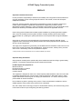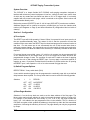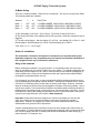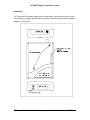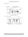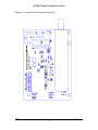
1
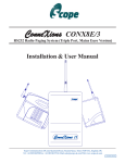
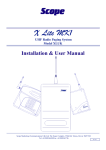
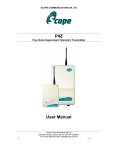
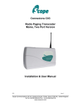
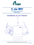
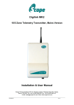
SCOPE COMMUNICATIONS UK LTD SCPUHF Four Zone POCSAG Paging Transmitter User Manual Scope Communications UK Ltd Quantum House, Totnes, Devon TQ9 5AL England. Tel: 01803 860700 Email: [email protected] SCPUHF Issue 2 SCPUHF Paging Transmitter System PREFACE Important Installation Information It is the purchasers’ responsibility to determine the suitability of this equipment and its derivatives for any given application, Scope cannot give specific advice in this manual, as each use will require independent evaluation. Scope has, wherever possible, employed extra safeguards to monitor the system’s performance. Certain system installations, operational requirements or budgets may, however, limit the effectiveness of these safeguards. Again, the suitability of the system for any given application must therefore be decided by the installer and their customer, relative to the application and risk. Good working practice dictates that a suitable system installation log must be generated, together with a record of the dates when the system has been manually checked, (with the aid of signal strength meters etc.) enabling the system performance to be compared with the original installation data. Scope has no control of the use and application of the frequencies issued by OFCOM. Some equipment that is licensed may have greater protection than other equipment which is operated on a WT Act License Exempt basis. The supply of this equipment is governed by our standard terms and conditions of sale, which can be found on the reverse of all order acknowledgements*, proforma invoices*, delivery notes, price lists and invoices. Alternatively, these can be provided on request. * Faxed proforma invoices and quotations refer to “conditions available upon request”. Important Safety Information Scope products are designed to operate safely when installed and used according to general safety practices. The following requirements should be observed at all times. Do NOT subject this equipment to: Mechanical shock Excessive humidity or moisture Extremes of temperature Corrosive liquids This equipment is designed for indoor use, unless expressly stated otherwise, and must not be used in classified Hazardous Areas, including areas containing explosive or flammable vapours, unless express authorisation has been given in writing by the manufacturer. If in doubt, consult your local product dealer for further information. Do not obstruct any slots or openings in the product. These are provided for ventilation to ensure reliable operation of the product and to protect it from overheating. Only use a damp cloth for cleaning (not liquid or aerosol based cleaners), and ensure that any power is removed from the unit prior to beginning the cleaning operation. SCPUHF Issue 2 2 SCPUHF Paging Transmitter System Preface Important Safety Information Removal of covers from the equipment must only be undertaken by authorised service personnel, who must ensure that power is isolated prior to removal. Installation Installation must only be undertaken by an Approved contractor, who shall ensure that all work is carried out in compliance with IEE Wiring Regulations. For mains powered equipment, a readily accessible isolating fuse or switched socket must be located within 1 metre of the equipment. No User Serviceable Parts Alteration or modification to any part of this equipment, without the prior written consent of the manufacturer, will invalidate all Approvals and Warranties attaching to the equipment. Further liability for the operation of the equipment, under the applicable law, will pass to the user, who will absolve the manufacturer of any further responsibility for it’s correct operation and use. This product complies with the essential requirements of the R&TTE Directive 1999/5/EC Copies of the Declaration of Conformity covering this product can be obtained from Scope at Quantum House, Steamer Quay, Totnes TQ9 5AL United Kingdom. Do not discard. At end of life this equipment must be sent to an authorised waste treatment centre. Contact Scope at the above address for further details. © Scope Communications UK Ltd, 2005 All Rights Reserved ******************************************************************************** SCPUHF Issue 2 3 SCPUHF Paging Transmitter System System Overview The SCPUHF is a simple flexible UHF POCSAG radio paging transmitter designed to interface with almost any control equipment. It has four “change of state” input zones, three of which are dry contact and one which has either a 12V or 0V trigger input. It is normally supplied with one numeric radio pager, which is matched to the system serial number and base transmitter identity code. Both mains powered (PSCPETX) and 12-14V dc input (SCPUHFTX) versions are available. Additional pagers can be ordered at anytime, provided that you have the chassis serial number (see diagrams on Page 8) and base transmitter ID (configuration label on inside of chassis). Section 1: Configuration a) Zone Inputs The RESET input will inhibit operation if closed. When it is opened all zone inputs must be in the non operational/standby state. The reason for this is that the processor will read the condition of the zones when the RESET input is closed and programs all zones as inactive at that time. For this reason we do not recommend the use of this terminal other than to enforce a program change. We suggest the use of a shunt switch for each zone required to be inhibited, as this will allow the zones to be selectively or collectively inhibited as and when required. Four zoned inputs are provided, zones 1-3 (volt free, dry contact) can be programmed N/O or N/C whereas zone 4 will accept either a +12v or 0v trigger but not both. All zones are programmable change of state. The condition of each zone is read at the time of applying power to the unit or after closing the RESET input. You may apply a continuous positive or negative to zone 4 if required. Provided that this condition is present at the time of opening the RESET input, it will expect the +12v or 0v to be removed to trigger the zone. b) Switch Program Options REPEAT DELAY: 2 way switch bank (SW1) A zone which remains triggered can be programmed to continually page with a pre defined delay between these repeats. The 2-way switch bank is used to select the following periods. Switches 1 OFF ON OFF ON 2 OFF OFF ON ON PERIOD NO REPEAT 12 SECS 60 SECS 120 SECS c) Base Pager Number Switches 1-6 on the 8-way bank are used to set the base address of the first pager. The binary value read on these switches is used to increment the pager numbers in steps of 8. For example, if the switches are set to binary 5 (1 on, 2 off, 3 on), the pager number will have 5 x 8 = 40 added to the pre-programmed value in the software. This is a function of POCSAG encryption which enables the address to be picked up within the first transmitted word frame, increasing the efficiency of the unit. The pager identity can only be programmed by Scope. SCPUHF Issue 2 4 SCPUHF Paging Transmitter System d) Mode Setting There are 3 modes available. These are set on switches 7 and 8 on the 8-way bank (SW2). The following modes are available: Switches 7 Mode 1 Mode 2 Mode 3 OFF ON OFF 8 FUNCTION OFF OFF ON 1 PAGER NUMBER, INDICATING 4 INDIVIDUAL ZONES 4 PAGER NUMBERS, INDICATING 1 INDIVIDUAL ZONE 2 PAGER NUMBERS, INDICATING 2 INDIVIDUAL ZONES 1) This will display [1] on Zone 1, [2] on Zone 2, [3] on Zone 3 and [4] on Zone 4* 2) This will provide each of four pagers with [X] one zone each, when their respective input is triggered. 3) This will provide pager 1 with the display [1] on Zone 1 and display [2] on Zone 2. It will provide pager 2 with the display [3] on Zone 3 and the display [4] on Zone 4*. *Note: Zone 4 is + or – 12V dc trigger Section 2: Installation The information contained in this Section is intended for use by authorised system installation engineers only. Unqualified personnel should not undertake installation of this equipment under any circumstances whatsoever. Siting of the hardware Before locating the hardware in any given location, it is important to take into account the range of operation that you require to obtain from your system. The standard transmitter can quite easily provide ranges of up to a mile or more and will provide excellent propagation on most industrial sites, covering a considerable area with just a quarter wave antenna (BNC terminated) connected directly to the unit. For coverage of very large sites, or where exceptionally difficult operating conditions exist, it may be advantageous to install an external antenna. Installing the transmitter on the second or third floor of a building will more often than not boost overall range. However, horizontal range is not always required as much as propagation through a multi-storey building. Here it may be more useful to use a small external antenna mounted outside the building at half the building height. Sometimes range is required more in one direction than in the other: moving the aerial to one side of the building can provide a bias in the required direction, which may overcome the range difficulties. (See section: Other Antennas). Important: coaxial feeds which are longer than 5 metres must employ low loss 50 ohm coax. We normally do not recommend feeds of more than 15 metres for standard applications. However, we suggest you contact our technical department where other considerations may prove this to be impractical. A further consideration that must be taken into account is the length and location of the dry contact cables. To avoid interference and possible false triggering, cable runs should be kept to a minimum (ideally less than 10 metres) and should be isolated from other cabling (e.g. mains, telecoms. PC networks, etc). SCPUHF Issue 2 5 SCPUHF Paging Transmitter System Some major points to consider when installing equipment: 1 Never install antennas near or adjacent to telephone, public address or data communication lines or overhead power cables. 2 Avoid, where ever possible, running antenna coax alongside other cables. 3 Avoid mounting the transmitter in the immediate vicinity of telephone exchanges or computer equipment. 4 Always use 50 ohm coaxial cable between the antenna and the transmitter. If cable runs exceed 5 metres, always use low loss 50 ohm cable such as RG213 or UR67. Coaxial cable intended for TV, Satellite or CCTV installations is normally 75 OHM and therefore totally unsuitable for any transmitter installation manufactured by Scope. 5 Also remember that the performance of the system will be effected by the type of material the unit is mounted on and its surroundings. The following is a list of materials that this transmitter will be adversely affected by if mounted on or if mounted in close proximity to: a) b) c) d) Foil back plasterboard Metal mesh or wire reinforced glass Metal sheeting, large mirrors or suspended ceilings Lift shafts All of the above can reflect radio waves and thereby reduce the capability of the transmitter to perform its desired functions. 6 The circuit boards within this equipment may be harmed by Electrostatic Discharge (ESD). Installers should ensure that both themselves and the system’s chassis are grounded before beginning any installation, and should ensure that adequate antistatic procedures are adhered to at all times. 7 Warning! Never transmit without an aerial attached to the transmitter 8 Warning! Carefully check the Installation section in this manual covering terminal connections prior to installation. Damage caused by incorrect connection is the responsibility of the installer! The following procedure must be adhered to when installing the SCPUHF paging system. Ensure you have taken into consideration all of the above information before selecting the location for your transmitter. If in doubt please feel free to telephone the technical helpline on (01803) 860710. 1 Remove the cover from the SCPUHFTX transmitter unit by undoing the two Pozi head screws located on the front face of the unit (see Diagram 1). For the mains powered PSCPETX transmitter, slacken the two screws at either end of the cover (see Diagram 2). 2 Carefully lift off the cover and place to one side. SCPUHF Issue 2 6 SCPUHF Paging Transmitter System 3 The transmitter should be fixed to an even wall surface using suitable screws fitted through the three holes provided in the chassis plate. Hold the chassis up to the chosen location and with the aid of a pencil mark the position of the mounting holes. Warning: Do not use the chassis plate as a template for drilling the holes into the wall. Hammer drills vibrating through the chassis may irreparably damage the quartz crystals on the printed circuit boards. 4 Place the transmitter over the mounting holes and secure the unit with suitable screws. Check that the chassis plate does not bend and that the screws do not snag or pinch any of the internal cables. 5 Connect the antenna to the unit via the BNC connector located at the top of the housing. If the antenna is an external antenna, or an antenna which is separate from the transmitter unit itself, ensure that the previous criteria covered under the section headed Siting of the Hardware, have been strictly adhered to (also see section headed Other Antennas). 6 Connect the input cables to the zone terminals. Note: Zones 1-3 are “dry contact” (no voltage) inputs. Applying voltage to these inputs will cause irreparable damage. Zone 4 requires either a +12V or 0V dc input. If in doubt, check with Scope before proceeding; incorrect connection may cause permanent damage. 7 For the SCPUHFTX unit, connect the power input lead to the + and – terminals provided (see diagram 3). Voltage must be 12 to 14V dc max. For the mains powered PSCPETX unit, connect the mains cable to a fused spur (5A minimum rating) located within 1 metre of the unit. 8 Replace the cover and refit the retaining screws. 9 With power applied, the red Power LED on the front fascia of the SCPUHFTX (or on the lower end plate of the PSCPETX) will light. 10 The system is now active and will transmit the zone number message for each of the zones when triggered (dependent on configuration: see Mode Setting, above). SCPUHF Issue 2 7 SCPUHF Paging Transmitter System Installation The Transcoder PCB contains static sensitive components. Care should be taken to avoid contact wherever possible and anti-static precautions should be observed during installation. Diagram 1: SCPUHFTX SCPUHF Issue 2 8 SCPUHF Paging Transmitter System Diagram 2: PSCPETX Case Top Panel View Case Securing Screws (slacken to remove cover) Case Bottom Panel View SCPUHF Issue 2 9 SCPUHF Paging Transmitter System Section 3: Operation The controller is in the sleep mode for most of the time, and will wake up every 1.2 seconds to read the inputs. If the RESET input is closed, the inputs are effectively disarmed and no pages will be sent, regardless of the input states. If the RESET input is open, the zone inputs will be compared to the states they were in when the board was powered up, or the last time the RESET input was closed. To change the state of any or all zones, ensure that the zones are set in their standby mode and close the RESET input. This will cause the Green TX LED to light momentarily when the state of the inputs is being read. The transmitter has now been programmed to accept the input condition as standby. Changing the condition of any input will cause the transmitter to send a page applicable to that input. Inputs must change state for a minimum of 1.5 seconds to ensure activation of the transmitter, although any changes in state of more than 300 milliseconds may initiate a transmission for that zone. This will depend on the time position of the processor relative to its wake up command. This requirement allows the standby current to run at less than 300uA. It also ensures freedom from possible inductive false triggers which could be caused by mains spikes etc. Any zone which remains in the triggered state will cause the Green TX LED to blink every 1.2 seconds. When this is not flashing it indicates that all zones are clear. If the Green TX LED continues to blink, it indicates that one or more inputs remain in a triggered state. If you are sure that all zones are inactive and in their standby condition and the Green TX LED is blinking, you must perform a RESET to update the inactive status of the unit. You must close the RESET input until the Green TX LED lights, or the new status will not have been reprogrammed. The maximum required close time for the RESET is 3 seconds. The system is configured so that only one input can be triggered at one time. It is therefore necessary to hold inputs from potential multiple trigger conditions for longer periods. 1 potential input at one time requires 1.5 seconds trigger 2 potential inputs at the same time requires 3 seconds trigger 3 potential inputs at the same time require 4.5 seconds trigger 4 potential inputs at the same time require 6 seconds trigger. Transmission time for any message should not exceed 1.5 seconds. All triggers are individually flagged and if the transmitter is set to repeat, all will repeat until each input reverts to its original state. Problems and Fault Finding. 1 Check that the input cables are connected to the active zones. 2 For Zones 1-3, ensure that no voltage is present on the input cables. Also, check that cable runs are not excessive (preferably less than 10 metres) and are not in close proximity to other mains or telecoms cabling. 3 Check that the pagers are at least 3 metres from the transmitter and aerial. Under certain conditions it is possible to flood the pager receivers and corrupt the data received. 4 Check that the pagers have the battery installed with the correct polarity and are correctly powered up. SCPUHF Issue 2 10 SCPUHF Paging Transmitter System 5 Check that the power source is the correct type (12 to 14V dc) and correctly wired to the terminals provided (see diagram 3). 6 Check that the green LED lights for the duration of the transmission. If not, go back to the cabling and re-check the terminal connections. 7 Check that the aerial is correctly installed. ************************************************************** SCPUHF Issue 2 11 SCPUHF Paging Transmitter System Diagram 3: Transcoder PCB terminal connections SCPUHF Issue 2 12 SCPUHF Paging Transmitter System Other Antennas The range and performance of this equipment can be improved by the addition of more efficient antennas*. These can be installed either inside or outside the building and are connected to the transmitter with 50 OHM coaxial cable. Glass mount antenna (UHFGM): for installation on the inside of a suitable window. This can boost range, especially if it is required in one direction from the building. The centre fed half wave di-pole, measuring approximately 12 inches from tip to tip, will provide excellent all round local signalling. This can be mounted either inside or outside a building. Two versions are available: 1) a light duty antenna suitable for sheltered environments/internal installation (LUHFDP). 2) a heavy duty stainless unit with optional mounting hardware for more arduous applications (UHFDP). The 6dB end fed colinear (UHF6DB): for external application. When elevated, this will boost overall range at a slight loss to some local signals. Pre-terminated coaxial feeder cables are available for 5, 10 or 15 metre requirements. Note ! High frequencies can equate to high power losses. Always use quality cable. RG58 is only acceptable on cable runs of up to 5 metres. We recommend RG213, or equivalent, on greater lengths. If in doubt consult our Technical Department. *subject to license conditions. Specifically, mounting height and Effective Radiated Power (ERP). Service Information Pagers returned with flat, incorrectly installed or leaking batteries will be charged for! In the event that a pager requires service, return it directly to Scope in the pre-addressed service bag supplied with your system by registered post. Ensure that you carefully fill out the service form provided. Failure to complete this form in full will result in inevitable delays! If you experience a problem with your equipment you must first telephone our service hotline on (01803) 860740, where we may request that you undertake a few simple checks. If a problem still remains, we will arrange collection of your system by overnight carrier at our expense. Upon receipt, we will endeavour to service or replace the system within 24 working hours and return the same by overnight carrier. We suggest that you retain the packaging for your control equipment. Incorrectly packed goods returned for service are the responsibility of the customer. If we deem that new packaging is required before we can return the unit, a charge will be made. Record your system details here for quick reference:Date supplied____/____/____ Serial Number of the Transmitter ___________________ Transmitter frequency ___________________MHz Transmitter Type approval SERILINK Number of pagers supplied with the system _______ System base ID number__________ Transmitter baud rate ______________ For information on individual pager types, refer to the appropriate pager manual SCPUHF Issue 2 13 SCPUHF Paging Transmitter System System Specification System Operating Voltage: 12 to 14V dc System Power Consumption: less than 250uA (microAmp) standby, 300mA transmit. Transmitter: Power output: 500mW Frequency band: 459 MHz Channel Spacing: 25 KHz Adjacent Channel: better than 200nW @ 4.5 KHz deviation TX Baud Rate: 512 baud Type Approval: EN 300 224 Type Approval No. SERILINK Notified Body No: 0891 General: Ports: 4 zone inputs (1-3 = dry contact, 4 = +12V or 0V) Open Collector (siren) output: 1A max Footprint (mm): PSCPETX: 328 (L) x 190 (W) x 75 (D) max SCPUHFTX: 184 (L) x 138 (W) x 45 (D) max excluding aerial Scope’s policy is one of continuous development and specifications are subject to change without prior notice SCPUHF Issue 2 14