1
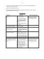
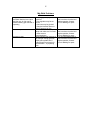
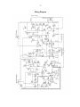
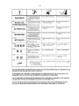
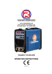
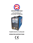
www.r-techwelding.co.uk
email: [email protected]
Tel: 01452 733933
Fax 01452 733939
C-MIG 315
COMPACT MIG WELDING MACHINE
OPERATION INSTRUCTIONS
Version 2014-1
2
3
Thank you for selecting the R-Tech C-MIG 315 Compact Mig Welder. We want you to take pride in
operating our C-MIG 315 as much pride as we have taken in making this product for you.
PLEASE EXAMINE CARTON AND EQUIPMENT FOR DAMAGE IMMEDIATELY
When this equipment is shipped, title passes to the purchaser upon receipt from the courier.
Consequently all claims for material damaged in shipment must be made by purchaser against the
transportation company used.
Please record your equipment identification below for future reference. This information can be found on
data plate at rear of machine.
Product C-MIG315
Serial No. ___________________________________
Date of Purchase _____________________________
Where Purchased _____________________________
Whenever you request replacement parts or information on this equipment please always supply
information you have recorded above
This product is covered by 2 years collect and return UK warranty, R-Tech will cover cost of collection,
repair and return of item to UK mainland (other areas are RTB). External items, torch, earth lead etc are
covered by 3 months warranty. Any faults/damage found caused by customer will be charged pro-rata.
Please read this operator manual completely before attempting to use this equipment.
Pay particular attention to the safety instructions we have provided you for your protection
The level of seriousness to be applied to each section is explained below
WARNING
This statement appears where the information must be followed exactly to avoid serious personal
injury.
CAUTION
This statement appears where the information must be following to avoid a minor personal injury or
damage to this equipment.
4
Installation
Technical Specifications
Model No.
R-Tech C-MIG 315
Input
MIG Operation
415V 3 ~ AC 50/60Hz
Rated Input Power
Rated Input Current
Rated Output Current
Duty Cycle @ 315AMPS
Duty Cycle @ 200AMPS
Output current Range
No Load Voltage
Voltage Adjustment Range
Suitable Wire Diameter
Gross Weight
Insulation
6.2 KVA
18 AMPS
315 AMPS
40% @ 40ºC
100% @ 40ºC
40-315 AMPS
38V MAX
16V – 33V +/- 3V
0.8mm 1.0mm 1.2mm
82 KG
Class F
Safety Precautions
Read entire section before starting installation
WARNING!
Electric Shock can kill – Only qualified personnel should perform this installation. Turn off input
power at the fuse box before working on this equipment. Do not touch electrically live parts. Always
connect the machine to an earthed mains supply as per national recommended standards.
Select suitable location
Place the welder where clean cooling air can freely circulate in and out of the front & rear louver
vents. Dirt, dust or any foreign material that can be drawn through vents into welder must be kept to
a minimum. Failure to observe these precautions can result in excessive operating temperatures
which can lead to plant failure.
Grinding
Do not direct grinding particles towards the welder. An abundance of conductive material can cause
plant failure.
Stacking
This machine cannot be stacked.
5
Transport – Unloading
Never underestimate the weight of equipment, never move or leave suspended in the air above
people. Use recommended lifting equipment at all times.
WARNING!
Falling Equipment can cause injury. Never lift welder with gas bottle attached. Never lift above
personnel.
Tilting
Machine must be placed on a secure level surface or on a recommended undercarriage/trolley.
This machine may topple over if this procedure is not followed.
Environmental Rating
The welding power source carries the IP21S rating. It may be used in normal industrial and
commercial environments. Avoid using in areas where water / rain is around.
Read and follow the ‘Electric Shock Warnings’ in the safety section if welding must be performed
under electrically hazardous conditions such as welding in wet areas or water on the work piece.
Machine grounding and High Frequency Interference Protection
This welder must be grounded to earth. See national electrical codes fro proper grounding
methods.
The high frequency generator being similar to a radio transmitter may cause interference to radio,
TV and other electronic equipment. These problems may be the result of radiated interference.
Proper grounding methods can reduce or eliminate this.
Radiated interference can develop in the following ways
1.
2.
3.
4.
Direct interference from welder power source
Direct interference from the welding leads
Direct interference radiated from feedback into power lines
Interference from re-radiation by un-grounded metallic objects.
Keeping these contributing factors in mind, installing equipment as per following instructions should
minimize problems.
1. Keep the welder input power lines as short as possible and enclose as much of them as
possible in metal conduit or equivalent shielding. There should be a good electrical contact
between this conduit and ground (Earth).
2. Keep the work and electrode leads as short as possible. Tape the leads together where
practical.
3. Be sure the torch and earth leads rubber coverings are free from cuts and cracks that allow
welding power leakage
6
4. Keep earth lead connection to work in good condition – Clean area on workbench where
earth clamp is situated on a regular basis.
Input Connections
Make sure the voltage, phase and frequency of input power is as specified on machine rating plate
located at rear of machine.
Have a qualified electrician provide suitable input power as per national electrical codes. Make sure
machine is earthed / grounded.
Make sure fuse or circuit breaker is correct rating for machine. Using fuses or circuit breakers
smaller than recommended will result in ‘nuisance’ shut off from welder inrush currents even if
welding at low amperages.
On multiple voltage input welders, be sure the machine is connected as per the instructions for the
voltage being supplied to welder – Failure to follow these instructions can cause immediate failure
within the welder and void machines warranty.
WARNING!
ELECTRIC SHOCK CAN KILL
Turn the input power OFF at the mains switch & fuse box before working on this equipment.
Have a qualified electrician install & service this equipment.
Allow machine to sit for 5 minutes minimum to allow the power capacitors to discharge before
working inside this equipment.
Do not touch electrically live parts
The C-MIG 315 Mig Welder requires a 415V 50/60Hz 3-Phase supply. It requires an 18A supply. It
comes with a 3 metre mains cable attached.
Connect wires according to national coding.
Brown wire – Live
Blue wire – Live
Black wire - Live
Green/Yellow Wire – Earth (Ground)
7
Connections for C-Mig 315
Setup machine as per two diagrams below:
Rear machine connections
Front machine connections
Connect Euro type Mig torch to euro torch connector
To avoid shock keep the Mig torch in good condition and replace if any of the insulation is
damaged.
Connect the earth lead (negative - ) to work/bench.
Connect the gas input hose to gas regulator, Set gas flow/pressure to 10-14 LPM, in drafty or open
areas a higher flow may be required to stop porosity of weld.
Make sure gas bottle is secured machine securely to avoid injury.
8
Operation
SAFETY PRECAUTIONS
WARNING!
ELECTRIC SHOCK CAN KILL
Do not touch electrically live parts or electrode with skin or wet clothing.
Insulate yourself from work and ground
Always wear dry insulating gloves
WARNING!
FUMES AND GASES can be dangerous
Keep your head out of fumes & gases produced from welding.
Use ventilation or exhaust to remove fumes & gases from breathing zone and general area.
WARNING!
WELDING SPARKS can cause fire or explosion
Keep flammable material away from work area.
Do not weld on containers that have held combustibles
WARNING!
ARC RAYS can burn
Wear eye, ear and body protection – Make sure work area is protected by proper shielding to
avoid injury to passers by.
Product Description
The R-Tech MIG is a member of our field acclaimed family of welding products. Premium features
include:1. 40% Duty cycle at 315Amps @ 40ºC
2. Heavy Duty 4-Roll geared wire feed unit for long working life and consistent wire feeding.
3. 21 settings of welding voltage to allow fine tuning of weld characteristics
9
4.
5.
6.
7.
Adjustable burnback control
Spot Welding & stitch welding facilities
Digital Amp & Volts meters
Euro type torch fittings for easy torch fitment/replacement
Recommended Processes
The R-Tech C-MIG315 is recommended for the MIG welding processes within its output capacity of
315 Amps DC
Equipment Limitations
The R-Tech C-MIG 315 is protected from overloads beyond the output ratings and duty cycle as per
machine specifications with thermostat protection of the output coils and rectifiers.
Welding Capability – Duty Cycle
The R-Tech C-MIG 315 is rated at 315 Amps at 40% duty cycle on a ten minute basis. If the duty
cycle is exceeded a thermal protector will shut machine off until the machine cools.
Controls and Settings
Front Panel
10
Set required voltage for welding material – Coarse voltage is set via 3 position switch either low,
medium or high range – Fine adjust is set via 7 position switch.
Adjust wire feed speed to suit voltage/wire diameter chosen.
Current LED shows actual welding voltage when welding
Voltage LED shows actual welding voltage when welding
Spot Timer – Sets how long spot weld will be
Stitch Time – Sets interval of stitch weld time
Power switch – Turns machine on/off
Power light – lights when machine turned on
Warning Light – lights when fault occurs (Overworking of machine – overheating)
Rear Panel
15 Amp Fuse – Protection fuse for 110V auxiliary
110V Aux - 110V Auxiliary output for water cooling system etc.
11
Side panel
Burnback adjustment – This sets amount of time welding power stays on after torch button released
and wire feed has stopped. If too little Burnback is set, wire may stick to work after trigger released,
if too much Burnback is set wire will Burnback into welding tip.
Wire reel holder – remove retainer screw cap and fit wire reel and refit securing screw cap. The reel
holder features an internal adjustable breaking system so that reel of wire stops quickly when torch
trigger released, other wise wire reel would continue for a few seconds causing wire to come of
sides of reel and cause tangle (birds nest)
Wire feed assy – make sure rollers are correct size for wire diameter selected, to change rollers
release retaining knurled head screw fit rollers onto shafts making sure the right size groove is in
line with wire and refit retaining screws. Do not over tighten wire feed pressure rollers as this can
cause premature motor and roller failure. TIP: Correct way to adjust tensioners is to slacken off
pressure so that wire does not feed, slowly adjust pressure until wire feeds smoothly, you should be
able to stop wire feeding by holding wire and it should slip on rollers. If you have too little pressure
wire will slip when welding causing unwanted Burnback into tips, if you have too much pressure
wire can snag in rollers when wire hits work and cause wire tangle by rollers.
Welding operation
Once you have set machine up as per above instructions press the torch trigger to start welding,
gas will flow from torch and main welding power will start and wire feed will start and once wire has
touched workpiece welding will start, to stop welding release torch trigger.
Adjust wire feed speed to give desired weld characteristics –
Less wire = Dip transfer welding
More wire = Spray transfer welding
TIP: Inside wire feed lid is chart with approximate recommended welding power settings required
for various sizes of material. Chart also shown below
12
13
Maintenance
Routine and periodic maintenance
WARNING!
ELECTRIC SHOCK CAN KILL
Turn the input power OFF at the mains switch & fuse box before working on this equipment.
Have a qualified electrician install & service this equipment.
Allow machine to sit for 5 minutes minimum to allow the power capacitors to discharge before
working inside this equipment.
Do not touch electrically live parts
1. Periodically remove the side/top panels of machine and clean out machine with a low
pressure dry air line paying particular attention to PC Boards, Fan blades, HF points
2. Inspect input and output cables & hoses for fraying, cuts & bare spots
3. Keep tig torch and cables in good condition
4. Clean air vents to ensure proper air flow and cooling
5. The fan motor has sealed bearings which requires no maintenance
Troubleshooting
Service & repair should only be performed by R-Tech welding trained personnel. Unauthorized
repairs performed on this equipment may result in danger to the technician and machine operator
and will invalidate your warranty. For your safety and to avoid electric shock, please observe all
safety notes and precautions detailed throughout this manual
The troubleshooting guide is provided to help you locate possible machine malfunctions.
Simply follow the 3 step procedure below
Step 1 Locate problem (symptom)
Look under the column labeled ‘Problem (symptoms)’. This column describes possible symptoms
that the machine may exhibit. Find the listing that best describes the symptom that the machine is
exhibiting
Step 2 Possible Cause
14
The second column labeled ‘possible cause’ lists the obvious external possibilities that may
contribute to the machine symptom
Step 3 Recommended course of action
This column provides a course of action for the possible cause, generally it states to contact
R-Tech welding for repair of machine.
Output Problems
Problems
Machine is dead – No Output –
No fan
Symptoms
1 Make sure the input switch is
in the ‘ON ‘ position
2 Check the input voltage at
the machine. Input voltage
must match the rating plate.
Refer to installation in this
manual.
Fan runs normally at power up
– No output from machine
Fan runs –No output form
machine and the warning light
on control panel is lit.
Fan runs – Machine does not
respond to torch switch.
Problems
Machine regularly overheats –
warning light on front panel lit.
Fan runs but machine has no
output
3 Blown or missing fuses on
mains input.
Check for proper input voltages
as per rating plate.
Welding application may have
exceeded recommended duty
cycle. Allow the unit to run until
fans cools the welder and the
light goes out.
The torch switch is faulty.
Check for continuity on torch
trigger wires or replace torch.
If torch is working then suspect
PCB failure or broken wiring.
Symptoms
1 Welding application may
exceed recommended duty
cycle – Reduce the duty cycle
of job.
2 Dirt and dust may have
clogged the cooling vents.
Blow out machine with dry,
clean low pressure air.
3 Air vents may be blocked due
to inadequate clearance
around machine
Rec. Course of action
If all recommended areas of
fault have been checked and
problem persists, Contact
R-Tech Welding for repair.
As Above
As Above
As Above
Rec. Course of action
If all recommended areas of
fault have been checked and
problem persists, Contact
R-Tech Welding for repair.
15
Mig Weld Problems
No gas flow when torch switch
activated. Machine has output
and fan runs. A click can be
heard indicating gas solenoid is
operating
Poor weld penetration
Porosity in weld
1 Gas supply is empty or
turned off
2 Flow regulator may be set
too low
3 Gas hose may be pinched
4 Gas pipe blocked. Blow out
with low pressure air line
Check condition of earth lead &
clamp and make sure it is fitted
to clean area on
bench/workpiece.
Check gas flow from torch tip, if
you cant get enough gas flow,
adjust gas regulator flow if
bottle has gas check torch for
gas restriction – try replacing
torch
If all recommended areas of
fault have been checked and
problem persists, Contact
R-Tech Welding for repair.
If all recommended areas of
fault have been checked and
problem persists, Contact
R-Tech Welding for repair.
If all recommended areas of
fault have been checked and
problem persists, Contact
R-Tech Welding for repair.
16
Electrical Schematic Diagram
17
Wiring Diagram
18
19