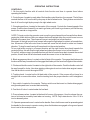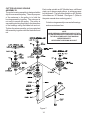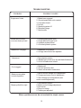
1
Operator’s Manual for MODELS: KHKW36151 KHKW48171 Professional Quality Lawn Care Equipment since 1945 Thank you for buying a YAZOO/KEES! Before operating your new mower, read, understand and follow the important safety instructions and the other instructions contained in this manual. Lawnmowers and all power equipment, can be potentially dangerous if used improperly. SAFETY REQUIRES GOOD JUDGEMENT, CAREFUL USE IN ACCORDANCE WITH INSTRUCTIONS AND COMMON SENSE. MANUAL 106541 REV. 01(12/18/01) Congratulations on the purchase of your Yazoo/Kees mower. This manual has been prepared for the owners and operators of the Hydro Kutter™ 36" and 48" commercial mowers. Read, understand and follow the saftey and operating instructions. ! WARNING Failure to follow cautious operating practices can result in serious injury to the operator or other persons. The owner must understand these instructions, and must allow only trained persons who understand these instructions to operate the mower. Each person operating the mower must be of sound mind and body and must not be under the influence of any mind altering substance. If you have any questions pertaining to your mower contact your dealer. ! CAUTION 1. Keep all shields, guards and safety devices in place and in proper working condition. 2. Stop engine and remove spark plug wires or remove key before adjusting, servicing, or performing maintenance. ! WARNING ! THE ENGINE EXHAUST FROM THIS PRODUCT CONTAINS CHEMICALS KNOWN TO THE STATE OF CALIFORNIA TO CAUSE CANCER, BIRTH DEFECTS OR OTHER REPRODUCTIVE HARM. WARNING Continuous dedication to improve our products require that specifications and design are subject to change without notice. 2 TABLE OF CONTENTS SAFETY: MAINTENANCE: 1. Training 1. Engine oil level 2. Preparation 2. Pump belt 3. Operation 3. Mower blades 4. Transportation 4. Safety interlock system 5. Maintenance 5. Hardware 6. Air cleaner SETUP AND ADJUSTMENTS: 7. Engine oil 1. Cutting height 8. Hydraulic oil 2. Motion control linkage 9. Tire presure 3. Reverse spring detent 10. Belts 4. Blade belts 11. Lubrication 5. Engine belt guides 12. Fuel filter 6. Pump belt 13. Hydraulic filter and oil 7. Safety interlock system 14. Cutter housing OPERATING INSTRUCTIONS: 1. Controls 2. Starting and operation TROUBLE SHOOTING: 3 SAFETY TRAINING: 1. Read this manual carefully and question your dealer if something is not clear. 2. Be thoroughly familiar with the controls and proper use of the equipment. 3. Never allow children, teenagers, or people unfamiliar with these instructions to use the mower. 4. Do not mow while people, particularly children, or pets are nearby. PREPARATION: 1. The use of personal protective equipment such as (but not limited to) protection for the eyes, ears, feet and head is recommended. 2. Never operate the mower without proper guards, covers, safety switches and devices in place and properly functioning. Inspect these items daily for their condition and proper operation. If the condition or operation of any of these devices is questionable they must be replaced or repaired before using the mower. 3. Thoroughly inspect the area to be mowed and remove all stones, sticks, wire and other debris that may be thrown by the mower. Also note or mark other obstacles such as holes, stumps, etc.. 4. Do not operate the mower when barefoot or wearing open shoes. Always wear substantial footwear and long pants. 5. Fill gas tank before starting mower. DO NOT SMOKE near gasoline containers. Do not fill gas tank indoors or when engine is hot or running. Clean off any spilled gasoline before starting the mower. OPERATION: 1. Mow only in daylight or good artificial light. 2. Do not operate the mower in wet grass if possible. 3. Mow across slopes. Use extreme caution when mowing or turning on slopes. Always turn to the downhill side. Do not mow excessively steep slopes ( mower may tip over and cause injury or death ). 4. Use caution when backing up. 5. Stop the blades when crossing surfaces other than grass; or when traveling to and from the area to be mowed. 6. Never operate the mower with defective, broken or excessively worn parts. Keep all guards, shields, and safety devices in place and in proper working order. 7. Do not change the engine governor settings or over speed the engine. Operating the engine at excessive speeds will increase the hazard of injury and can severely damage your machine. 8. Keep hands, feet and clothing away from rotating parts when operating mower. 9. Stop the blades and engine before leaving the operators position for any reason. 10. Never make adjustments to the mower while engine and/or blades are running. 11. After striking a foreign object, stop mower and remove key. Inspect the mower for any damage and repair it immediately before continuing to mow. 12. Never operate this equipment in an enclosed or confined area without proper ventilation of the engine exhaust. 13. Do not allow any passengers to ride on the mower. Keep others away from the mower when in operation. 4 SAFETY TRANSPORTATION: Turn off fuel valve and strap mower to trailer. MAINTENANCE: 1. Keep all nuts, bolts and screws tight to keep mower in safe operating condition. 2. Engine maintenance should comply with engine manufactures specifications. See the engine manual for specifications. 3. Never store the mower with gas in the tank inside a building where fumes can reach an open flame or spark. 4. To reduce the risk of fire, keep the mower free of grass, leaves and excessive grease or oil. 5. Have your mower inspected and serviced each year by an authorized Yazoo/Kees dealer. 6. Use only authentic Yazoo/Kees replacement parts to insure the safety and quality of your mower is maintained. 7. Safety decals should be replaced if they are missing or illegible. Decals can be purchased from your Yazoo/Kees dealer. 8. The hydraulic system including all hoses and fittings should be checked frequently for wear or leaks. Never check for leaks with your hands, use a piece of cardboard or wood. Hydraulic oil under pressure could be injected into your body and must be surgically removed within a few hours. EQUIPMENT SETUP AND ADJUSTMENTS 1. Uncrate mower 2. Mount front caster assemblies to the front deck using the fasterners provided on the deck.(both sides) 3. Cut the plastic wire ties holding the operator presence levers down. 4. Check tire pressure in all four tires. (rear tires 15 PSI, front tires 20-25 PSI) 5. Check engine oil with dipstick. Add if needed per engine manufactures specifications.(See engine manual) 6. Check hydraulic oil level. Should be an 1.0” below the bottom of the fill tube. 7. Mount the discharge chute to the front deck using the fasteners provided on the deck. CUTTING HEIGHT 1. Before changine cutting heights make sure the blades are off, key switch is off, and remove spark plug wire or wires. 2. Cutting height ranges from 1 1/2” to 5” in 1/4” increments. 3. Cutting height can be changed three ways. Move one “C” spacer on the front casters, change the blade spacers, or move the wheel motor assemblies. 4. a. To change heights on the rear deck lossen, do not remove, the top two carraige bolts on both sides.(see fig. 1a) b. Place a jack under the center of the rear deck remove the bottom two nuts on both sides. Then remove the bottom two bolts both sides.(May have to raise the jack slightly to remove bolts.)(see fig. 1b) c. With the jack raise or lower the rear deck to the desired postion using the chart, on page 7, to ensure proper height. 5 d. Reinstall the bottom two bolts on both sides.(A tapered punch may be needed to help align the holes.) e. Retighten all four bolts both sides and remove jack. 5. Using the chart(on page 7), find the correct number of spacers to be placed under the caster swivel.(see fig. 2) NOTE: To achive the best quality cut, the blades should be level with the ground or slighty tipped forward. REAR DECK ADJUSTMENT CARRIAGE BOLTS(a) POSTION A POSTION B POSTION C (b) Figure 1 CASTER HEIGHT ADJUSTMENT MACHINERY BUSHING 1/2" C- SPACERS CASTER SWIVEL Figure 2 6 CUTTING HEIGHT ADJUSTMENT CHART AXLE POSITION NUMBER OF SPACERS BELOW CASTER ARM NUMBER OF 1/4" BLADE SPACERS UNDER CUTTER HOUSING 4 3 2 1 0 4 3 2 1 0 4 3 2 1 0 4 3 2 1 0 4 3 2 1 0 4 3 2 1 0 0 A 1 2 B 3 4 C 5 Note: To quickly achive small changes in cutting heights, move the spacers from under the cutter housing to above the cutter pulley. (Each spacer moved will give an additional 1/4" of cutting height ). CUTTING HEIGHT (IN INCHES) 1 1/2 1 3/4 2 2 1/4 2 1/2 2 2 1/4 2 1/2 2 3/4 3 2 1/2 2 3/4 3 3 1/4 3 1/2 3 3 1/4 3 1/2 3 3/4 4 3 1/2 3 3/4 4 4 1/4 4 1/2 4 4 1/4 4 1/2 4 3/4 5 USE ONLY 4 BLADE SPACERS MAXIMUM MOTION CONTROL ADJUSTMENT 1. This adjustment must be made with the drive wheels rotating. Raise rear of the unit and block it up so the wheels are free to rotate. CAUTION: Keep hands, feet and clothing away from rotaing tires. 2. It will be necessary to make this adjustment with the reverse detents disconnected. 3. With the ground speed lever in neutral or stop position, start the engine. 4. The thumb latches should be unlocked. 5. Turn the adjusting nut the proper direction until the wheel stops rotating. This is your neutral postion, repeat on other side. (see fig. 3) 6. After the neutral postion is adjusted. You will need to readjust the short linkage. (see fig. 3) 7. Remove the two hairpins, swing the linkage out of the control lever and the thumb latch. (see fig.3) 7 8. Turn the short linkage the proper direction in the swivel, so that when the thumb latch is engaged the wheel doesn’t turn(or it is in neutral). Reinstall the hairpins and repeat on other side. (see fig. 3) 9. After these adjustments have been made it will be necessary to adjust the reverse detent.(See reverse spring detent adjustment) Figure 3 REVERSE SPRING DETENT ADJUSTMENT 1. To check if your reverse spring detent adjustment is set right. Make sure your ground speed lever is pulled back to the neutral position. Release the thumb latchs(both sides) and pull up on the control levers at the same time. Then release the levers, it should return to neutral. If it does not, the following adjustmtents need to be made. 2. Stop engine and remove key. 3. Ground speed lever should be in the neutral or stop postion and the thumb latchs unlocked. 4. Loosen the two 1/4” bolts holding the reverse detent bracket. Slide the bracket up or down till it just touchs the “L” shape stop under the console. Holding the bracket against the stop retighten the two 1/4” bolts.(Repeat on other side if needed.) (see fig. 4 ) Figure 4 (Right side cut away view of console.) 8 BLADE DRIVE BELT ADJUSTMENT 1. Before performing adjustments on blade belt, turn the mower off and disconnect spark plug wire or wires. 2. Remove front deck belt shield. 3. Loosen nut on turnbuckle. 4. Set belt tension when blade engagement lever is in the engaged position. 5. To increase belt tension rotate turnbuckle toward the rear of the mower until desired tension is gained. Do not over tighten belts, to much tension will reduce belt and spindle bearing life. (see fig. 5) AUXILIARY BLADE BELT 1. Before performing adjustments on blade belt, turn the mower off and disconnect spark plug wire or wires. 2. To adjust tension on the auxiliary belt rotate nut on linkage that is attached to deck strap located on the right side of cutter deck.(see fig. 5) TURNBUCKLE AUXILARY BELT ADJUSTMENT ROD 1/4" IDLER PIVOT POINT ENGAGEMENT IDLER ASSEMBLY Figure 5 9 ENGINE BELT GUIDES 1. Before performing adjustments on belt guides, turn the mower off and disconnect spark plug wire or wires. 2. Belt guides under the engine should be adjusted as shown in figure 6. Figure 6 PUMP BELT 1. Before performing adjustments on pump belt, turn the mower off and disconnect spark plug wire or wires. 2. Check tension on the belt. If it feels loose adjustment will need to be made. 3. Loosen the nut on the bottom of the idler pulley. 4. Slide the idler pulley against the belt, retighten the nut while applying pressure to the idler pulley. (see fig. 6) INTERLOCK SAFETY SYSTEM The interlock modules functiuon is to prevent the engine form starting if the blade and/or ground speed lever are engaged. It also causes engine shutdown if the operator falls from, or attempts to leave the operator position while the blades or ground speed lever are engaged. After tthe engine starts, the operator must hold either the left or right O.P. lever down before engaging the blades or moving the ground speed lever. If niether O.P. lever is held the engine will stop. Check the function of the safety electrical system o aregular basis. 1. Engine must kill if blades are engaged without O.P. levers held down. 2. Engine must kill if ground speed lever is taken out of neutral without holding down O.P. levers. 3. Engine must not start unless blades are off and ground speed lever is in the neutral position. 4. Do not operate the mower if the interlock safety system allows operation or starting in any unsafe condition. 10 OPERATING INSTRUCTIONS CONTROLS: 1. Be thoroughly familiar with all controls their function and how to operate them before operating the mower. 2. Control levers: Located on each side of the handle control direction of movement. The left lever controls the flow of oil from the left hydro pump to the left wheel motor. The right lever controls the flow of oil from the right hydro pump to the right wheel motor. 3. Ground speed lever: Located in the center of the console. Controls the forward speed of the mower. Push the lever forward if you want to go faster, pull it back to go slower or pull it all the way back to the neutral or stop postion. NOTE: To begin motion the operator must move the ground speed lever forward before disengaging the thumb latches. After you release the thumb latches allow the control levers to move forward at the same time. The mower will move in a straight line in that direction. Movement of the right control lever forward will cause the right wheel to rotate in a forward direction. Movement of the left control lever forward will cause the left wheel to rotate in a forward direction. To stop forward travel pull levers back into the neutral position. To turn right while moving in a forward direction pull the right control lever back towards the neutral position, this will slow the right wheel and cause the mower to turn in that direction. To turn left while moving in forward direction pull the left control lever back towards the neutral position, this will slow the left wheel and cause the mower to turn in that direction. 4. Blade engagement lever: Located on the left side of the console. To engage the blades push the lever all the way forward and to disengage the blades pull the lever back against the console. 5. Choke and throttle control: Located on the right side of the console. Push the throttle control all the way forward for choke. Use when starting cold engine do not run choke when engine is warm. Use the throttle to control the engine RPM. 6. Tracking knob: Located on the left back side of the console. If the mower will not travel in a straight line on a smooth surface, turn the tracking knob the proper direction until it straightens out. 7. Key switch: Located on the console. The key switch must be turned on, blades disengaged, and ground speed lever in neutral before starting. 8. Fuel shut off valve: Located under the fuel tank. 9. Pump release valves: Located at the back left corner of the pumps. Used to release the system so unit may be moved by hand when not running. NOTE: Only rotate about a 1/4 to 1/2 of a turn to release system. 10. Operator presence levers: Located on the handle. One or both levers must be pressed against the handle for the mower to remain running, when the blades are engaged or the ground speed lever is not in the neutral position. 11 OPERATING INSTRUCTIONS STARTING AND OPERATION: 1. Making sure the blades are disengaged, ground speed lever in neutral, the thumb latches locked, and the fuel valve on. 2. Adjust throttle to choke (if needed) turn key to on position. 3. Pull start the engine. Once the engine is running adjust the throttle. 4. Holding down at least one of the operator presence levers, engage blades and set RPM to maximum, but not choked. NOTE: Be sure all persons are clear of area before engaging the blades. To prolong spindle bearing and belt life engage and disengage blades at approximately 1\2 throttle. 5. Set the ground speed lever to the desired position. 6. Release the thumb latches at the same time. MAINTENANCE 1. Engine oil level: Check daily with engine cold and on a flat surface. Remove the dipstick and wipe clean. Reinsert the dipstick all the way,but do not screw down. Remove the dipstick and check oil level. If oil level is low add oil. Use engine manufacturers specs for type of oil. 2. Pump drive belt: Stop engine and remove key. Check the tension on the belt. 3. Mower blades: Stop engine and remove key. Inspect blades and sharpen or replace as needed. Check daily or more often if needed. The machine requires more power with dull blades and gives a poor cut. If blades get bent, replace them. Blades shouldn’t have any notches from hitting objects. The air foil on top of the blade should be sufficient to raise the grass for cutting. If blades are in good condition, sharpen at an angle of 22 to 28 degrees about 2-1/2 inches in from the tips. Note: After sharpening, check blades for proper balance, if needed correct balance to prevent excessive vibration. 4. Safety interlock system: Check daily and never operate the mower if this system is not functioning properly. 12 MAINTENANCE 5. Hardware: Stop engine and remove key thoroughly inspect the entire machine for any missing or loose hardware. Check daily. 6. Air cleaner: Stop engine and remove key. Remove plastic cover and loosen wingnut on the air cleaner. Remove the foam pre-cleaner and wash or replace if needed. Inspect paper filter and replace if dirty. Check every 25 hours, daily if in very dirty conditions. Fuel efficiency, engine RPM, and available power goes down rapidly if the air filter is dirty. Prolonged effects could damage the engine. 7. Engine oil: Change oil to manufacturers specifications. Stop engine and remove key. Drain oil when engine is warm. Thoroughly clean around cap before removing. Remove oil drain cap from the right side of engine block and replace drain cap. Remove oil filter and replace. Put a light coat of clean oil on the filter gasket before installing. Fill engine with oil using manufacturers specs, see Kawasaki owner’s manual. Start engine and idle slowly to allow the oil to recoat the interior of the engine and then inspect for leaks. 8. Hydraulic oil: Check daily. Thoroughly clean around cap. Remove cap. Oil level should be 1” below the bottom of the fill tube. If not, add oil. NOTE: Use only 15W - 50 MOBIL 1. 9. Tire pressure: Check every 25 to 50 hours. Rear tires require 15 psi and caster tires 20 psi 10. Belts: Check every 25 hours. Stop engine and remove key. Check the condition of all belts. 12. Lubrication (every 25 hours): Caster tires and front caster pivots (Clean grease zerk thoroughly before greasing) 13. Fuel filter: Replace annually or as needed. 14. Hydraulic filter and oil: Change every 500 hours or yearly. Stop engine and remove key. Clean around the filter and the drain plug on the bottom side of the tank. Remove the filter and allow any oil to drain from the filter head. Then replace with new filter. Use only Yazoo/Kees p/n 102606, filter which has a bypass valve and the correct micron filter. Remove one of the hydraulic lines from the bottom of the tank and allow the tank to drain, reinstall the hydraulic line. Fill tank with 15W - 50 MOBIL 1. 1” below the fill tube and replace cap. Block up the rear of unit until wheels will rotate freely and start engine at a slow idle, move the control levers forward and run for several minutes. Stop engine and recheck oil level. If wheels don’t response an air lock has occured within the hydraulic system. Bleed air from lines, or let stand overnight to allow the air time to dissipate out of the oil. Retry responses & check the oil level. Note: Serious damage to the pumps and wheel motors can occur if the system is ran with an air lock. 13 CUTTER HOUSING SPINDLE ASSEMBLYS The cutter housing assembly is designed with a slip fit inner race and pulley. The sole purpose of the setscrew in the pulley is to hold the housing assembly together. The setscrew is not ment to secure the pulley. The pulley is secured by pinching the pulley to the inner race of the bearings using the blade bolt and nut. Tighten the setscrews after you have pinched the assembly together with the blade bolt and nut. Each cutter spindle on 48" Models have a different stack up of spacers and pulleys, to achieve proper belt alignment. The left cutter spindle on 48" Models is the same as 36" Models. See figure 7 (Refer to the parts manual when ordering parts.) Cutter housing assemblys use sealed bearings and are maintance free. NOTE WHEN PRESSING A BEARING IN OR OUT OF A CUTTER HOUSING APPLY CONSTANT PRESSURE TO THE RACE OR RACES THAT HAVE AN INTERFERENCE FIT. NEVER BEAT A BEARING IN OR OUT. Figure 7 14 TROUBLE SHOOTING PROBLEM POSSIBLE CAUSES Engine won’t start 1. Blade lever engaged. 2. Ground speed lever not in neutral. 3. Fuel valve closed. 4. No fuel. 5. Spark plug wires off. 6. Bad spark plugs. 7. Bad module. Mower will not move or moves slowly or hard 1. Pump bypass valves open. 2. Pump drive belt loose or off. 4. Hydraulic system failure. 5. Air in the hydraulic system. Blades won’t engage 1. Blade belt off of pulleys. 2. Linkage unhooked or not adjusted. Uneven cut 1. Tire pressure uneven. 2. Blades bent (check tip to tip one blade thickness) 3. Air foil of blade worn or bent. Cut is ragged 1. Blades dull. 2. Ground speed too fast. 3. Grass accumulation under deck. Mower moves when in neutral position 1. Motion control linkage out of adjustment. 2. Pump arms loose or out of adjustment. 3. Short linkage out of adjustment.(see motion control adjustment) Mower pulls left or right 1. Tire pressure uneven. 2. Motion control linkage adjustment. 3. Soft terrian. 4. Slope too steep. 5. Tracking not adjusted. When a problem occurs, do not overlook the simple causes. 15 SERVICE RECORD DATE DESCRIPTION OF WORK DONE 16 SERVICE DONE BY