1
08-01016-01
Elastic Networks
YesWare
Applications User’s Guide
Software Release 2.30
Document Revision 2.30.1
Publication Date: October 2000
Elastic Networks
YesWare
Applications User’s Guide
Software Release 2.30
Document Revision 2.30.1
Publication Date: October 2000
2000 Elastic Networks
All rights reserved
All information contained in this document is subject to change without notice. Elastic Networks reserves the right to make changes
to equipment design or program components, as progress in engineering, manufacturing methods, or other circumstances may
warrant.
EtherLoop is a trademark of Elastic Networks.
Software Release 2.30
YesWare Applications User’s Guide
08-01016-01
iv
Software Release 2.30
YesWare Applications User’s Guide
08-01016-01
v
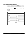
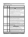
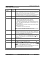
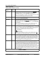
Publication history
Document
Release
Date
Description
Document
Revision 2.30.1
October 2000
Document Final release with comprehensive index and
minor terminology changes.
Document
Revision 2.30
September 2000
Document Pilot release, incorporating PMS integration,
Print Services, Conference Room Billing, and ftp included in
YesWare Software Release 2.30
Document
Revision 2.30
(Beta)
August 2000
Document Beta Draft release including restructuring and
incorporate some features added for YesWare Software
Release 2.30
Revision 2.20
November 1999
Document released to incorporate features added for
YesWare Software Release 2.20
Revision 2.00
April 1999
Document released to initial release of YesWare suite of
applications (release 2.00). Previous documents published
under separate titles: NSS InterProxy, NSS Maintenance,
NSS Inventory & Provisioning.
Software Release 2.30
YesWare Applications User’s Guide
08-01016-01
vi
Software Release 2.30
YesWare Applications User’s Guide
08-01016-01
vii
Contents
About this document
xv
Audience
Software version note
xv
xv
SECTION I
VISITOR-BASED NETWORKS AND YESWARE
Introducing Visitor-Based Networking and YesWare
1-1
YesWare features new for 2.3
New and enhanced billing capabilities
Enhanced Modem Billing for EtherLoop modems
Visitor printing services
Visitor-based networking
Challenges of the VBN
VBN service-provider benefits
YesWare and VBN
Advantages of a YesWare VBN
Creating a YesWare VBN
Local host network connection requirements
Visitor computer requirements
Visitor internetwork access
InterProxy-based internetwork access
YesWare VBN transport systems
EtherLoop-VBN
Ethernet-VBN
Combined EtherLoop/Ethernet VBN
Service and billing options
Guest Room Billing
Credit-Card Billing
Authorization Code billing
Conference Room Billing
VBN billing methods and the Port Use Context
VBN billing configurations
Enhanced Modem Billing
Ethernet Port Billing
Modem Connection Billing
1-2
1-2
1-2
1-2
1-3
1-3
1-3
1-4
1-4
1-4
1-5
1-5
1-6
1-6
1-8
1-8
1-10
1-12
1-14
1-15
1-15
1-15
1-15
1-15
1-17
1-18
1-19
1-20
Software Release 2.30
YesWare Applications User’s Guide
08-01016-01
viii Contents
Visitor access controls
Port Validation
Visitor authentication
VBN web site customization
VBN page customization
Virtual Concierge
Service-provider branding
Service-provider home/splash page configuration
System management and maintenance capabilities
Installing a YesWare VBN system
Organization of this manual
1-22
1-22
1-23
1-24
1-24
1-24
1-24
1-25
1-26
1-27
1-27
YesWare Server operating system and software modules
2-1
YesWare 2.3 software functions and versions
YWS operating system
EON commands
Using YesWare web-based modules
Connecting to the ETH 0 interface
Browsing to the ETH 0 URL
Finding an unknown ETH 0 IP address configuration
YWS web interface login user name and password default
YesWare main web page
YesWare modules/sections/functions
YesWare web-based modules
About NSS
Conference Scheduler
Download Utilities
Billing Manager
EtherCraft
InterProxy
Modex Daemon
NSS Maintenance
Print Services
Port Manager
SNMP Proxy Agent
Install or Upgrade
2-2
2-3
2-3
2-4
2-4
2-4
2-4
2-5
2-5
2-6
2-8
2-9
2-10
2-11
2-12
2-13
2-14
2-15
2-16
2-17
2-18
2-20
2-21
Software Release 2.30
YesWare Applications User’s Guide
08-01016-01
Contents ix
SECTION II
YESWARE INSTALLATION AND CONFIGURATION
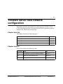
YesWare Server host network configuration
3-1
YesWare Server
YWS functional components
YesWare Server console connection methods
YWS keyboard/monitor connections
YWS PC/VT-100 connection
YWS telnet connection
YesWare Server console interface
EON login default
EON commands
Configuring the YWS host network interface
Setting the YWS date and time
Setting the DNS nameserver(s) for the YWS
3-2
3-2
3-4
3-4
3-5
3-5
3-7
3-7
3-8
3-9
3-13
3-15
InterProxy VBN configuration
4-1
InterProxy module functions
Backup InterProxy
Configure Remote Access
Virtual Concierge
Configure Proxy IP Address
TFTP Daemon Manager
InterProxy VBN system configuration
InterProxy functional architecture
InterProxy limitations for visitor computers
InterProxy configuration procedure
InterProxy Configuration Page
Configuring the InterProxy network connection
4-2
4-2
4-2
4-2
4-2
4-2
4-3
4-3
4-3
4-4
4-4
4-9
VBN gateway and Network Services System
switch configuration
5-1
Configuration requirements
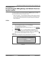
Provisioning the VBN gateway and Network Services System switch
5-2
5-3
Software Release 2.30
YesWare Applications User’s Guide
08-01016-01
x Contents
SECTION III
YESWARE SERVICE PROVISIONING
EtherLoop system provisioning
6-1
Enhanced Modem Billing provisioning requirements
Enhanced Modem Billing CO modem provisioning
Enhanced Modem Billing CPE modem provisioning
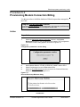
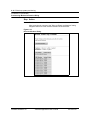
Provisioning Enhanced Modem Billing
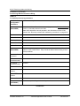
Modem Connection Billing provisioning requirements
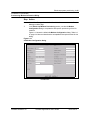
Modem Connection Billing provisioning dialogs
Provisioning Modem Connection Billing
EtherLoop modem management provisioning requirements
EtherLoop modem management system requirements
Provisioning EtherLoop modem management with a resident YWS
Provisioning EtherLoop modem management with a non-resident YWS
EtherLoop modem MAC addressing conventions
6-2
6-2
6-2
6-3
6-12
6-12
6-13
6-20
6-20
6-22
6-23
6-25
Provisioning the Ethernet-VBN switches and ports
7-1
Ethernet-VBN switch architecture and configuration requirements
7-2
Ethernet-VBN architecture provisioning requirements
7-2
Ethernet-VBN configuration requirements
7-3
Ethernet-VBN configuration example notes
7-4
Ethernet-VBN TCP/IP addressing guidelines
7-5
Ethernet-VBN switch and port configuration
7-6
Switch Configuration dialog
7-6
Port configuration
7-8
Provisioning the Ethernet-VBN switch and port database
7-10
Verifying Ethernet-VBN Architecture
7-14
Testing the Ethernet-VBN system Configuration
7-16
Viewing Real-Time Switch Status
7-18
Ethernet-VBN switch maintenance
7-21
Upgrading Ethernet-VBN switch firmware using TFTP and HTTP Proxy 7-22
Using the Refresh Switches function
7-25
Using the View Database function
7-26
Testing Ethernet-VBN ports
7-27
View Port Test Results
7-27
Port Test
7-27
Software Release 2.30
YesWare Applications User’s Guide
08-01016-01
Contents xi
YesWare service billing
8-1
Billing Manager feature description
Guest Room Billing
Billing protocol and time settings
Billing rate configuration
Guest Room Billing and PMS integration
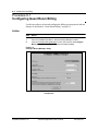
Configuring Guest Room Billing
Credit Card Billing
Credit Port Use Context assignment
Authorize.Net merchant account
Credit Card Billing configuration
Configuring Credit-Card Billing
Authorization Code Billing
Authorization Code duration and expiration
Authorization Code Port Use Context assignment
Using Authorization Code Billing
Generating Authorization Codes
YesWare billing record management capabilities
Guest Room Billing record management
Credit Card Billing record management
Authorization Code Billing record management
Billing record reports
Retrieving and deleting SDR logs using ftp
Creating billing record reports
8-2
8-3
8-3
8-3
8-3
8-4
8-7
8-7
8-7
8-7
8-8
8-10
8-10
8-10
8-10
8-11
8-13
8-14
8-14
8-14
8-14
8-15
8-17
YesWare PMS integration
9-1
YesWare PMS integration process
YWS connection to the PMS
YesWare PMS interface configuration
YWS direct connection to PMS
YWS isolated connection to PMS
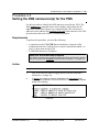
Connecting the YWS to the PMS
HOBIC AckNak configuration requirements
HOBIC One-Way configuration requirements
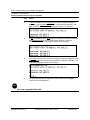
Configuring the PMS Interface
Generating a Test Record for the PMS
SNMP notification of PMS link disruption
SNMP trap configuration requirements
HOBIC AckNak Threshold 1 selection requirements
HOBIC AckNak Threshold 2 selection requirements
SNMP trap recipient configuration
Configuring SNMP trap recipient for PMS link disruptions
9-2
9-2
9-2
9-3
9-4
9-5
9-7
9-12
9-14
9-15
9-16
9-16
9-16
9-17
9-17
9-18
Software Release 2.30
YesWare Applications User’s Guide
08-01016-01
xii Contents
Customizing the VBN web site
10-1
VBN page customization
VBN page construction
Tasks required for VBN page customization
YesWare VBN pages
Using <VBN SHOW> tags
<VBN SHOW> tags used for visitor authentication
<VBN SHOW> tags used for port and service information
<VBN SHOW> tags used for VBN graphics
Branding and home/splash page configuration
Branding Configuration dialog
Custom Look and Feel configuration
Creating the custom VBN web site
Configuring the Virtual Concierge
10-2
10-2
10-2
10-3
10-4
10-4
10-5
10-6
10-7
10-7
10-8
10-11
10-13
YesWare conference room and meeting services
11-1
Conference Room Billing
Conference Scheduler network architecture
Conference Room Billing using Conference Scheduler
Conference Scheduler administrator requirements
Conference Scheduler operator requirements
Conference Scheduler visitor requirements
Configuring Conference Room Billing
Scheduling conference room IP addresses
Configuring visitor computers for Conference Room Billing
Port-based meeting scheduling and billing
Port-based conference billing
Administrator requirements for port-based conference services
Operator requirements for port-based conference services
Visitor requirements for port-based conference services
Scheduling port-based meeting rooms
11-2
11-2
11-3
11-3
11-3
11-3
11-4
11-6
11-10
11-12
11-12
11-12
11-12
11-12
11-13
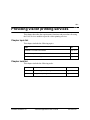
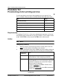
Providing visitor printing services
12-1
YesWare’s Print Services module
Print Services visitor printing requirements
Print Services module functions
Print Services printer requirements and limitations
Printer requirements
Printer limitations
Printer administrator requirements
Print Services visitor billing
Print Services billing method
Visitor PostScript file billing
Visitor PCL file billing
Provisioning visitor printing services
Using visitor printing services
12-2
12-2
12-3
12-4
12-4
12-4
12-4
12-5
12-5
12-5
12-5
12-6
12-15
Software Release 2.30
YesWare Applications User’s Guide
08-01016-01
Contents xiii
SECTION IV
YESWARE SYSTEM MANAGEMENT
YesWare security and administration
13-1
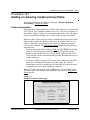
YesWare System Security
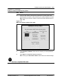
Adding or removing modem privacy filters
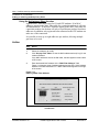
Using the Add privacy filters function
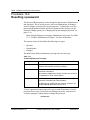
Restricting web access to the YWS
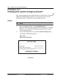
Changing the system manager password
Resetting a password
Routine Maintenance and Administration
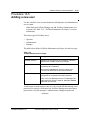
Adding a new user
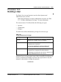
Deleting a User
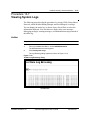
Viewing System Logs
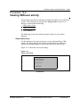
Viewing VBN user activity
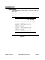
Show Active Users
Show User History
Trace Address
Configuring NTP (network time protocol)
Backup, Restore, Upgrade, Restart and Shut Down Procedures
Installing and Upgrading YesWare modules
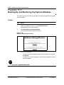
Backing Up and Restoring the System Database
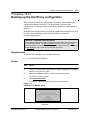
Backing up the InterProxy configuration
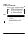
Restarting the YesWare Server
Shutting Down the YesWare Server
13-2
13-3
13-4
13-6
13-8
13-10
13-12
13-13
13-15
13-17
13-19
13-19
13-20
13-21
13-22
13-23
13-24
13-26
13-27
13-29
13-30
Using EtherCraft
14-1
EtherCraft feature description
Using EtherCraft
EtherLoop modem speeds and training counts
Check Speeds
Modem Details
Modem identification and version table
Ethernet Port Metrics
Speeds tables, modem speeds and training counts
HDLC Port Metrics
Client Addresses
Status
Version
Purpose of the Version function
Version page field values
Clear Logs
Get Logs
Reset Modems
14-2
14-2
14-2
14-6
14-7
14-8
14-8
14-9
14-10
14-11
14-12
14-13
14-13
14-13
14-14
14-15
14-16
Software Release 2.30
YesWare Applications User’s Guide
08-01016-01
xiv Contents
Using the Download Utilities module
Download Utilities purpose and function
Using Download Utilities
Downloader status and logs
Upgrading EtherLoop modem firmware
Upgrading from Generation 1 to Generation 2 modem firmware
15-1
15-2
15-2
15-2
15-3
15-6
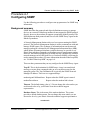
APPENDIX A
YESWARE MANAGEMENT USING SNMP
Remote YesWare Management using SNMP
A-1
YesWare SNMP components
YesWare supported MIBs
Using YesWare SNMP
YesWare SNMP web interface
Editing the SNMP configuration parameters
YesWare EtherLoop MIB
MIB modem tables and traps
Example SNMP Network Manager with EtherLoop MIB
EtherLoop Modem System Table
EtherLoop CO and CPE Id Tables
EtherLoop CO and CPE Statistics Tables
EtherLoop CO and CPE MAC Filter Tables
EtherLoop Traps
EloopSwitch MIB
EloopSwitch system objects
EloopSwitch Table
EloopSwitch Traps
MIB II System Group MIB
MIB II SNMP Group MIB
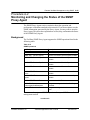
Configuring SNMP
Monitoring and Changing the Status of the SNMP Proxy Agent
A-2
A-2
A-3
A-3
A-3
A-4
A-4
A-5
A-5
A-7
A-9
A-11
A-13
A-14
A-14
A-15
A-17
A-18
A-20
A-23
A-25
Index
Software Release 2.30
I-1
YesWare Applications User’s Guide
08-01016-01
xv
About this document
1-
This document provides instructions for using the YesWare software suite to
manage an EtherLoop or Ethernet system.
Audience
The audience for this document includes network planners, installation
technicians, network administrators, and anyone who may be charged with
provisioning or maintaining the YesWare system.
Software version note
The YesWare 2.3 software release consists of a base 2.3 rvelease shipped on
the YesWare Server and a “super-patch” that must be applied by the Elastic
Networks Technical Assistance and Support (TAS) to make the release
fully-functional. This document covers the base software release with the
super-patch applied.
Software Release 2.30
YesWare Applications User’s Guide
08-01016-01
xvi About this document
Software Release 2.30
YesWare Applications User’s Guide
08-01016-01
SECTION I
VISITOR-BASED NETWORKS AND YESWARE
Software Release 2.30
Software Release 2.30
YesWare Applications User’s Guide
08-01016-01
1-1
Introducing Visitor-Based Networking
and YesWare
1This chapter introduces the concepts of visitor-based networking and the
purpose and function of YesWare in a visitor-based network.
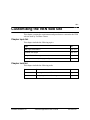
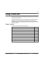
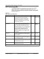
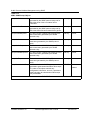
Chapter topic list
This chapter includes the following topics.
Topic
See
YesWare features new for 2.3
page 1-2
Visitor-based networking
page 1-3
YesWare and VBN
page 1-4
Visitor internetwork access
page 1-6
YesWare VBN transport systems
page 1-8
Service and billing options
page 1-14
VBN billing configurations
page 1-17
Visitor access controls
page 1-22
VBN web site customization
page 1-24
System management and maintenance capabilities
page 1-26
Installing a YesWare VBN system
page 1-27
Software Release 2.30
YesWare Applications User’s Guide
08-01016-01
1-2 Introducing Visitor-Based Networking and YesWare
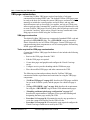
YesWare features new for 2.3
For users familiar with YesWare, this section summarizes the features now
available as part of the YesWare 2.3 release. For new users, the remainder of
this chapter describes Visitor-Based Networking (VBN) and YesWare’s VBN
features and capabilities in more detail.
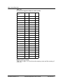
New and enhanced billing capabilities
Billing Manager enables system managers to track usage, authorize user
access, generate authorization codes, and transmit records to a hotel property
management system to produce consolidated billing. Billing Manager in
YesWare 2.3 has the following capabilities:
• improved Property Management System (PMS) integration - supports
the most widely used HOBIC interfaces used in hotel billing systems
• improved service logging and reporting functions - allows service
providers a variety of methods for generating reports and retrieving service
log information from the YWS
• Credit Card Billing - allows for in-room or point of sale high-speed
access ordering and payment using visitor credit cards
• Conference Room Billing - YesWare’s Conference Room Scheduler
reserves conference rooms based on IP addresses sold to attendees, and
automatically enables/disables the high-speed Internet access as needed.
Enhanced Modem Billing for EtherLoop modems
Enhanced Modem Billing enables EtherLoop modems to be managed and
billed like YesWare Ethernet ports, and prevents visitors from being
improperly billed for YesWare service.
Visitor printing services
The YesWare Print Services module allows guests to "click-and-print" files to
a specific networked printer such as in a business center or to the front desk.
Chapter 12, “Providing visitor printing services” describes the requirements
for implementing YesYare visitor printing services.
Software Release 2.30
YesWare Applications User’s Guide
08-01016-01
Introducing Visitor-Based Networking and YesWare 1-3
Visitor-based networking
Until recently, nearly all Ethernet local area networks (LANs) were private.
Developed for private use, owned and maintained by private organization,
these networks were focused on providing connectivity for a select group of
people such as employees. Everyone who used the network was supposed to
be able to use it, and the costs of providing that network were considered
overhead.
A Visitor-Based Network (VBN) is a network intended for use by temporary
users, such as hotel guests, who need a simple, temporary network connection
they can use quickly and easily without the assistance of an IT specialist.
Challenges of the VBN
Implementing a VBN presents special challenges to the service-provider.
Service billing, not usually a requirement in private LANs, must be carefully
monitored and controlled. Resource usage, which is governed almost
exclusively by happenstance in private LANs, must also be carefully
controlled. Visitor access must be authenticated, but must also be simple.
Visitor services must be platform-independent so that guests using a wide
range of platforms have access to VBN services.
VBN service-provider benefits
A VBN is a valuable service, and service providers who implement VBN
services can create tremendous new revenue and service opportunities within
several markets:
• Hospitality/convention centers
• Public convenience kiosks
• Training and seminar rooms
• Sales centers
• Press rooms
• Corporate meeting rooms
• University and business campuses
All of these areas have frequent, business-oriented visitors who would likely
use the services of a VBN if one were available. VBN service-providers who
want to serve these markets must provide simple connectivity to the VBN, and
also have ways to bill for access and control access through network
authentication.
Software Release 2.30
YesWare Applications User’s Guide
08-01016-01
1-4 Introducing Visitor-Based Networking and YesWare
YesWare and VBN
YesWare is a suite of system management software used to manage an
EtherLoop or Ethernet VBN (see “YesWare VBN transport systems” on page
1-8). YesWare software "modules" support the following VBN functions:
• seamless Internet or intranet access to "visitor" end-user computers
• host site customization and service branding
• visitor authentication and service billing
• system management and maintenance
Advantages of a YesWare VBN
YesWare makes it simple to deliver high-speed Internet access connectivity
for a VBN at any location/market. Its "guest-friendly" interface allows plugand-play simplicity for the mobile computer user, without special software
downloads or reconfiguration of TCP/IP settings.
In addition to solving Internet connectivity issues for end-users, YesWare has
several features that are key to generating new revenue streams for serviceproviders. The YesWare software suite provides port authorization controls
and automated billing for ports on EtherLoop modems and/or Ethernet
switches, allowing Internet access only to authorized, billable guest users.
YesWare also supports EtherLoop modem administration functions.
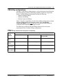
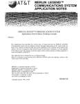
Creating a YesWare VBN
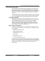
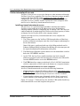
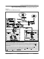
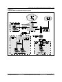
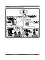
Figure 1-1 shows how simple it is to create a YesWare VBN. Virtually any
Internet-ready Ethernet LAN can become a VBN with the addition of the
YesWare Server (YWS) device. The YWS provides the necessary layer of
management between the network visitors and the Internet gateway router to
allow seamless connectivity for the visitors, with the host of features required
for service-providers to bill and control this access.
Figure 1-1
YesWare VBN versus the private LAN
C o nv en tio n a l
Priva te LA N
Ye sW a re
VBN
In te rn e t /
WAN
In te rn e t /
WAN
L AN /W AN
Ro uter
L AN /W AN
Ro uter
YW S ETH 0
Ye sW a re Se rve r
YW S ETH 1
Priva te
LA N
V is ito r-Ba se d
N e tw o rk
Software Release 2.30
YesWare Applications User’s Guide
08-01016-01
Introducing Visitor-Based Networking and YesWare 1-5
Local host network connection requirements
The network hosting the YWS must have the following:
• Ethernet 10/100Base-T termination for the YWS network interface
• network connection to an existing local area network (LAN) or wide area
network (WAN) router
• access to the Internet through an Internet Service Provider (ISP) or other
Internet account
• valid TCP/IP network address configuration (IP address, network mask,
gateway address) for the YWS.
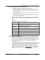
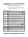
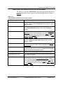
Table 1-1 on page 1-5 lists the protocol requirements for a network supporting
the YWS, based on the open systems interconnection (OSI) seven-layer
model.
Table 1-1
YesWare host network protocol requirements
OSI layer
YesWare Server protocol requirement
1/Physical
Category 5 unshielded twisted pair (UTP) wiring and
infrastructure with RJ-45 terminations
2/Data-link
IEEE 802.3 Ethernet 10Base-T
3/Network
Internet Protocol (IP)
4/Transport
Transmission Control Protocol (TCP)
5/Session
No specification
6/Presentation
No specification
7/Application
Internet Explorer 4.0+ or Netscape Navigator 3.0+
Visitor computer requirements
All YesWare visitor computers must have an Ethernet 10Base-T network
interface card (NIC) configured to use the TCP/IP networking protocol. This
means the visitor computer must either have a specified IP address, network
mask, and gateway, or be configured to use DHCP (Dynamic Host
Configuration Protocol).
A YesWare visitor computer can be configured with a TCP/IP address for the
resident LAN or a non-resident LAN. YesWare visitors can also be configured
for a random (non-existent) LAN, as long as the computer’s TCP/IP
configuration adheres to basic TCP/IP addressing rules. For example, an
YesWare visitor computer cannot be a duplicate of another visitor IP address
or have a "broadcast" address such as 255.255.255.255 as its assigned IP
address.
Software Release 2.30
YesWare Applications User’s Guide
08-01016-01
1-6 Introducing Visitor-Based Networking and YesWare
Visitor internetwork access
YesWare visitors receive access to the Internet or other internetwork through
YesWare’s InterProxy capability. The InterProxy function is unique in that it
accepts traffic from TCP/IP clients regardless of a client’s IP address
configuration.The following sections describe visitor internetwork access
using the InterProxy module, and the requirements visitor computers must
meet to receive InterProxy-based internetwork access.
InterProxy-based internetwork access
The InterProxy is a specialized network address translator that enables
YesWare visitors with non-local IP addresses to access the Internet or
company intranet without re-configuring any IP settings. One YWS unit can
connect hundreds of random/non-local visitors to the router/gateway of either
an Internet Service Provider (ISP) or the company intranet.
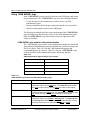
Visitors receiving InterProxy-based internetwork access complete the
following process:
1 The visitor connects to the YesWare VBN through either an EtherLoop
modem or Ethernet switch port, starts the visitor computer and attempts to
browse the Internet.
Note: If the port is configured with one of the billing methods used in
Enhanced Modem Billing or Ethernet Port Billing, the visitor must provide
the required authentication information at this point.
2
3
4
The EtherLoop or Ethernet system connects over an intermediate switch or
hub to the YWS ETH 1 interface.
At the YWS, the InterProxy module translates non-local visitor IP
addresses to appear local to the host network, and routes the VBN traffic
from the ETH 1 interface over to the ETH 0 interface.
The ETH 0 interface connects to the host LAN or LAN/WAN termination
which is connected to a WAN such as the Internet or a corporate intranet.
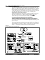
InterProxy-based limitations for visitor computers
InterProxy-based internetwork access has the following limitations:
• Visitors who have assigned IP addresses that are in the same subnet as the
ETH 0 IP address will not receive internetwork access (with the exception
of IP addresses provisioned using the Conference Scheduler module).
• Visitors that have a home page designated with the "don’t use proxies"
feature enabled for the home page will not receive internetwork access.
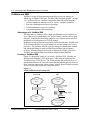
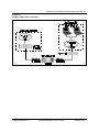
Figure 1-2 on page 1-7 illustrates how the YesWare VBN enables InterProxybased internetwork access and completes this process.
Software Release 2.30
YesWare Applications User’s Guide
08-01016-01
Introducing Visitor-Based Networking and YesWare 1-7
Figure 1-2
YesWare VBN system architecture
Software Release 2.30
YesWare Applications User’s Guide
08-01016-01
1-8 Introducing Visitor-Based Networking and YesWare
YesWare VBN transport systems
A YesWare VBN system can deliver service using EtherLoop modem pairs,
Ethernet switches, or a combination of both EtherLoop and Ethernet transport
systems. The following sections describe these YesWare VBN transport
systems.
EtherLoop-VBN
EtherLoop is an Ethernet-based modem technology that enables TCP/IP data
transmission simultaneously with voice service over the twisted-pair,
Category 3 (CAT 3) telephone lines of a local loop. EtherLoop technology
provides Ethernet-compatible service in locations out-of-range of standard
Ethernet LANs.
EtherLoop-VBN transport systems are ideal for data transmission in
environments such as hotel rooms that have no existing data network
infrastructure. EtherLoop delivers data transmission speeds comparable to
Ethernet at 5,000 feet and reliable service up to 21,000 feet. In addition to
guest room service, YesWare’s new Enhanced Modem Billing allows
EtherLoop modem pairs to serve any VBN service area, including conference
facilities and uncontrolled public areas.
Note: EtherLoop-VBN transport systems that use Enhanced Modem
Billing cannot be used simultaneously with Ethernet-VBN. See
“Combined EtherLoop/Ethernet VBN” on page 1-12 and “VBN billing
configurations” on page 1-17 for more information.
EtherLoop-VBN data transport method
Visitor computers connect physically to an EtherLoop-VBN transport system
as they would to a conventional Ethernet 10/100Base-T LAN, using an
Ethernet network interface card (NIC) and a Category 5 (CAT 5) cable
terminated with an RJ-45 connector. EtherLoop systems transmit TCP/IP data
and voiceband traffic using modem pairs configured in a point-to-point
architecture. EtherLoop modem pairs consist of a CPE (customer premise
equipment) modem and CO (central office) modem. Table 1-2 describes the
function of EtherLoop CPE and CO modems.
Table 1-2
EtherLoop modem pair functions
EtherLoop Function
Modem
CPE
modem
The CPE modem transmits visitor data and voice to its designated CO modem over the
Category 3 (CAT 3) facility phone network. The CPE modem connects to the visitor
computer through an RJ-45 connection on the back of the modem. The CPE modem also
has two RJ-11 jacks on its backplane. One RJ-11 connects to a phone in the room, and the
second RJ-11 connects to the wall-jack of the facility phone network.
CO
modem
The CO modem controls the traffic flow from the CPE modem to the YWS ETH 1 interface.
The CO modem resides in an EtherLoop multiplexer shelf, typically located in the facility
equipment room. The CO modem connects to the YWS ETH 1 interface via an intermediate
Ethernet switch or hub. The CO modems must be on the same LAN segment as ETH 1.
Software Release 2.30
YesWare Applications User’s Guide
08-01016-01
Introducing Visitor-Based Networking and YesWare 1-9
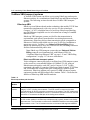
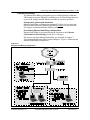
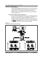
EtherLoop-VBN transport architecture
Figure 1-3 shows the transport architecture of an EtherLoop-VBN system.
Figure 1-3
YesWare EtherLoop-VBN transport system
EtherLoop terminology - CO=SE and CPE=CE
In YesWare modules, different terms are used in different modules for the EtherLoop modem pairs.
In some modules, the EtherLoop modem supporting the end-user/client computer is called CPE (for
Customer Premise Equipment), and the modem connecting to the YesWare Server is called CO (for
Central Office).
In other modules, the EtherLoop modem supporting the end-user/client computer is called CE (for Client
End), and the modem connecting to the YesWare Server is called SE (for Server End).
Except for the terms used, there is no difference between a CO modem and an SE modem, or between
a CPE modem and CE modem..
Software Release 2.30
YesWare Applications User’s Guide
08-01016-01
1-10 Introducing Visitor-Based Networking and YesWare
Ethernet-VBN
Ethernet-VBN systems are used in areas such as conference and meeting
rooms that have an existing Category 5 (CAT 5) Ethernet LAN infrastructure.
Visitor computers connect physically to the ports on Ethernet-VBN switches
as they would to a conventional Ethernet 10/100Base-T LAN.
Note: The Ethernet-VBN transport system cannot be used simultaneously
with the Enhanced Modem Billing method. See “VBN billing
configurations” on page 1-17 for more information.
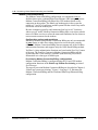
Ethernet-VBN transport architecture
Figure 1-4 shows an example of the YesWare Ethernet-VBN transport system
architecture. See “Ethernet-VBN architecture requirements” on page 1-11 for
the requirements to provision the Ethernet-VBN architecture.
Figure 1-4
Ethernet-VBN transport system
Software Release 2.30
YesWare Applications User’s Guide
08-01016-01
Introducing Visitor-Based Networking and YesWare 1-11
Ethernet-VBN architecture requirements
As shown in Figure 1-4 on page 1-10, Ethernet-VBN switches are set up in a
physical "tree" architecture. The YWS ETH 1 interface is provisioned as the
"Network Services System" at the "top" of the tree. The Network Services
System is provisioned as a single-port switch and serves as the VBN gateway
to the host LAN/WAN.
In addition, the following general requirements apply to all Ethernet-VBN
systems:
• Visitor computers must have a 10/100Base-T network interface card (NIC)
installed and appropriate cabling and adapters. See “Visitor computer
requirements” on page 1-5 for complete visitor computer requirements.
• A YesWare Ethernet-VBN system can support most enterprise-class
desktop switches comparable to the BayStack 303 or the Cisco 2900XL.
Ethernet-VBN switches can contain up to 24 ports (provisioned as ports
#1-24) and up to two high-speed/auxiliary ports (provisioned as
ports #25-26).
• All Ethernet-VBN switches must have assigned IP addresses. These IP
addresses must be identically assigned in both the switch console interface
and the YesWare Port Manager module.
• Ethernet-VBN switches that are "down" the switch architecture are
provisioned by configuring "downlink" ports in YesWare’s Port
Configuration dialog.
• Ethernet-VBN switches that are "up" the switch architecture are
provisioned as "Parent" switches.
• Each port connecting "down" to a switch must be configured with the
"downlink IP address" of the downlink switch.
• Each switch connecting "uplink" to a parent switch (all switches except the
YWS ETH 1) must be configured with the IP address of the parent switch.
Ethernet-VBN example
Using Figure 1-4 on page 1-10 as an example, note the following:
• "Ethernet Switch #1" is the parent switch of both "Ethernet Switch #2" and
"Ethernet Switch #3."
• The YWS ETH 1 interface is the parent of Ethernet Switch #1.
• For port #25 of Switch #1, the IP address of Ethernet Switch #2 must be
entered in the "Downlink IP Address" field of the Port Configuration
dialog.
• For port #26 of Switch #1, the IP address of Ethernet Switch #3 must be
entered in the "Downlink IP Address" field of the Port Configuration
dialog.
• For port #1 of the Network Services System (YWS ETH 1), the IP address
of Ethernet Switch #1 must be entered in the "Downlink IP Address" field
of the Port Configuration dialog.
Chapter 7, “Provisioning the Ethernet-VBN switches and ports” contains
complete instructions for using the Ethernet switch provisioning interface and
a more detailed architecture example.
Software Release 2.30
YesWare Applications User’s Guide
08-01016-01
1-12 Introducing Visitor-Based Networking and YesWare
Combined EtherLoop/Ethernet VBN
The combined EtherLoop/Ethernet system serves areas where VBN service is
required using both EtherLoop lines (CAT 3 wiring) and Ethernet switch ports
(CAT 5 wiring). YesWare’s Ethernet Port Billing method is used to support
the Ethernet (CAT 5) facility, while YesWare’s Modem Connection Billing
is used to serve the EtherLoop (CAT 3) facility.
Enhanced Modem Billing cannot serve combined application
Enhanced Modem Billing offers more capabilities than Modem Connection
Billing, and is the preferred method of EtherLoop modem billing. However, in this
release of YesWare, the two "port-based" billing methods (Enhanced Modem
Billing and Ethernet Port Billing) cannot be used simultaneously. For this
reason, in combined EtherLoop/Ethernet (CAT 3/CAT 5) facilities, Modem
Connection Billing must be used to serve the CAT 3 facility. See “VBN billing
configurations” on page 1-17 for more information.
Combined EtherLoop/Ethernet VBN system architecture
Figure 1-5 on page 1-13 shows the YesWare combined EtherLoop/Ethernet
VBN architecture.
Software Release 2.30
YesWare Applications User’s Guide
08-01016-01
Introducing Visitor-Based Networking and YesWare 1-13
Figure 1-5
Combined EtherLoop/Ethernet transport system
Software Release 2.30
YesWare Applications User’s Guide
08-01016-01
1-14 Introducing Visitor-Based Networking and YesWare
Service and billing options
YesWare systems can provide VBN services in the following functional
service areas:
• Guest rooms
• Conference rooms
• Public areas
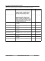
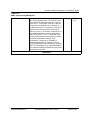
Table 1-3 describes each of these YesWare service options and lists the billing
methods available for each YesWare service option. The following sections
describe the requirements for the available billing methods.
Note: Chapter 8, “YesWare service billing,” describes how to implement
the YesWare billing methods.
Table 1-3
YesWare service and billing options
YesWare
Service Area
Service Description
Available Billing Methods
Guest rooms
Guest room service for hospitality
customers in hotel rooms.
• Guest Room Billing
• Credit-Card Billing
• Authorization Code Billing
Conference
rooms
Conference room service for
• Conference Room Billing
scheduled meetings and conferences. • Credit-Card Billing
• Authorization Code Billing
Public areas
Service for kiosks and other public
areas such as hotel lobbies where
access to the port is uncontrolled.
Software Release 2.30
• Credit-Card Billing
• Authorization Code billing
YesWare Applications User’s Guide
08-01016-01
Introducing Visitor-Based Networking and YesWare 1-15
Guest Room Billing
Guest Room Billing is used only in visitor guest rooms. Using this billing
method, Internet access charges appear on the Service Detail Record (SDR)
log for the room generated by YesWare. Guest Room Billing can be integrated
with the facility Property Management System (PMS) so that YesWare service
charges appear as an additional "room charge" on the guest room bill.
Credit-Card Billing
Credit-Card Billing can be used in any YesWare service area. Using this
billing method, YesWare Internet access charges appear on the customer’s
credit card bill. Credit-Card Billing requires that the YesWare service provider
have a merchant account with Authorize.Net, an Internet credit-card
processing company.
Authorization Code billing
Authorization Code billing can be used in any YesWare service area. Using
this billing method, customers pay service charges before YesWare Internet
access is granted. Authorization Code billing requires that the YesWare
service provider generate an "Auth Code" using the Billing Manager module.
Conference Room Billing
Conference Room Billing is used only in conference or meeting rooms. Using
this billing method, YesWare Internet access charges appear on the receipts
generated by YesWare’s Conference Scheduler module. Chapter 11, “YesWare
conference room and meeting services” describes the requirements and
procedures for using the Conference Scheduler module.
VBN billing methods and the Port Use Context
YesWare VBN billing methods are configured using the "Port Use Context"
provisioned for each VBN port (EtherLoop or Ethernet). Port Use Contexts
can be set to guest, credit, meeting, public, or network.
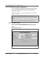
Note: The network Port Use Context is not a billable setting.
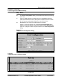
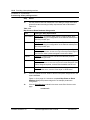
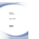
Figure 1-6 on page 1-16 shows an Ethernet Port Configuration dialog with
the Port Use Context of "guest." Table 1-4 on page 1-16 lists the Port Use
Context requirements for each of the YesWare billing methods.
Software Release 2.30
YesWare Applications User’s Guide
08-01016-01
1-16 Introducing Visitor-Based Networking and YesWare
Figure 1-6
Port Use Context in Ethernet Port Configuration
Port Use Context=guest
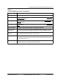
Table 1-4
Visitor-based networking Port Use Context requirements
Billing Method
Port Use Context requirement
Guest Room Billing
guest
Credit Card Billing
credit
Authorization Code Billing
meeting, public, or guest
Conference Room Billing
meeting
Software Release 2.30
YesWare Applications User’s Guide
08-01016-01
Introducing Visitor-Based Networking and YesWare 1-17
VBN billing configurations
YesWare’s VBN billing configurations are selected and provisioned based on
the VBN transport system(s) and billing method(s) required to support the
facility. YesWare billing configurations include the following:
• Enhanced Modem Billing
• Ethernet Port Billing
• Modem Connection Billing
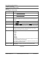
Table 1-5 lists the compatibility of each of these billing configurations with the
YesWare billing methods and transport systems. Note that Modem
Connection Billing is used only with the Guest Room Billing method in
Combined EtherLoop/Ethernet transport systems.
The following sections describe the billing characteristics and system
requirements of the YesWare billing configurations.
Table 1-5
YesWare billing methods and configuration compatibility
YesWare
Billing
Method
YesWare VBN Transport System
EtherLoop-VBN
Ethernet-VBN
Combined EtherLoop /
Ethernet-VBN
Guest Room Enhanced Modem Billing
Billing
Ethernet Port Billing
Modem Connection Billing
Credit-Card
Billing
Enhanced Modem Billing
Ethernet Port Billing
Ethernet Port Billing
Authorization Enhanced Modem Billing
Code Billing
Ethernet Port Billing
Ethernet Port Billing
Conference Enhanced Modem Billing
Room Billing
Ethernet Port Billing
Ethernet Port Billing
Software Release 2.30
YesWare Applications User’s Guide
08-01016-01
1-18 Introducing Visitor-Based Networking and YesWare
Enhanced Modem Billing
The Enhanced Modem Billing configuration serves facilities that have "allEtherLoop" VBN transport systems. Enhanced Modem Billing uses YesWare
billing methods to bill the EtherLoop CO modem port(s) provisioned in the
system. CPE modems are not billed, but are treated only as remote connection
ports that send traffic from the service area to the CO modem ports.
Configuration options and restrictions
Enhanced Modem Billing configurations support all YesWare service areas
and billing methods. However, Enhanced Modem Billing cannot serve
facilities that also support an Ethernet Port Billing configuration.
Provisioning Enhanced Modem Billing configurations
By default, Enhanced Modem Billing is not enabled. To implement an
Enhanced Modem Billing configuration, the feature must be enabled and
provisioned using the functions in the EtherLoop Port Provisioning section
of Port Manager.
The system requirements and procedures to enable and provision Enhanced
Modem Billing are described in Chapter 6, “EtherLoop system provisioning.”
Figure 1-7 illustrates the Enhanced Modem Billing configuration.
Figure 1-7
Enhanced Modem Billing configuration
Software Release 2.30
YesWare Applications User’s Guide
08-01016-01
Introducing Visitor-Based Networking and YesWare 1-19
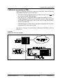
Ethernet Port Billing
The Ethernet Port Billing configuration serves facilities that have EthernetVBN transport systems. Ethernet Port Billing uses YesWare billing functions
to provision, manage and bill Ethernet switches on a port-by-port basis.
Configuration options and restrictions
Ethernet Port Billing configurations support all YesWare service areas and
billing methods. However, Ethernet Port Billing cannot serve facilities that
also support an Enhanced Modem Billing configuration.
Provisioning Ethernet Port Billing configurations
Ethernet Port Billing is provisioned using the functions in the Ethernet
Switch and Port Provisioning section of Port Manager.
The steps to provision Ethernet Port Billing are described in Chapter 7,
“Provisioning the Ethernet-VBN switches and ports.” Figure 1-8 illustrates the
Ethernet Port Billing configuration.
Figure 1-8
Ethernet Port Billing configuration
Software Release 2.30
YesWare Applications User’s Guide
08-01016-01
1-20 Introducing Visitor-Based Networking and YesWare
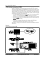
Modem Connection Billing
The Modem Connection Billing configuration is recommended only in
facilities that require combined EtherLoop/Ethernet-VBN transport systems.
Modem Connection Billing bills EtherLoop CPE modems based on any
connection to the modem. The EtherLoop modem pairs in the system are
polled at :17 and :47 of each hour, and the system bills the visitor if any traffic
is detected across the modem pair.
Because computers typically send continuous (but low-level) "I-am-herewhere-are-you" traffic, Modem Connection Billing bills even visitors who do
not use YesWare services or refuse the terms and conditions, but for whatever
reason remain connected to the modem.
Configuration options and restrictions
EtherLoop modems using Modem Connection Billing are only recommended
in guest rooms or other areas where physical access to the port is strictly
controlled. Modem Connection Billing does not support any of the YesWare
authentication functions, and supports only the Guest Room Billing method.
YesWare’s visitor authentication functions are based on the Port Use Context
of the port. The Port Use Contexts in Modem Connection Billing tell the
system only that a CPE modem is a billable (non-network) port, with no
information as to what type of billable port.
Provisioning Modem Connection Billing configurations
Modem Connection Billing is configured using the CO and CPE modem
configuration functions in the EtherLoop Modem Provisioning section of
Port Manager.
The steps to provision Modem Connection Billing are described in Chapter 6,
“EtherLoop system provisioning.” Figure 1-9 on page 1-21 illustrates the
Modem Connection Billing and the Combined EtherLoop/Ethernet billing
configuration.
Software Release 2.30
YesWare Applications User’s Guide
08-01016-01
Introducing Visitor-Based Networking and YesWare 1-21
Figure 1-9
Combined EtherLoop/Ethernet billing configuration
Software Release 2.30
YesWare Applications User’s Guide
08-01016-01
1-22 Introducing Visitor-Based Networking and YesWare
Visitor access controls
The following sections describe YesWare’s methods of controlling service
access and authentication capabilities for Enhanced Modem Billing and
Ethernet Port Billing configurations.
Note: Modem Connection Billing configurations do not support the visitor
access controls described in this section.
Port Validation
The authentication functions and service access controls used in YesWare’s
Enhanced Modem Billing and Ethernet Port Billing configurations depend on
having the port validation function enabled in the configuration dialog for the
Ethernet switch port or EtherLoop modem port. The port’s validation status
(true/false/undef) tells the system whether or not to present the visitor with the
authentication page.
If Port Validation is disabled ("false" or "undef"), visitors receive access
without authenticating or accepting any terms and conditions. If port
validation is enabled ("true"), visitors are directed to one of the authentication
pages and must provide the appropriate information to receive internetwork
access.
Note: Modem Connection Billing cannot use the authentication and
service access controls because Port Validation must be disabled for
Modem Connection Billing service.
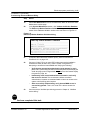
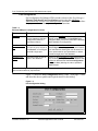
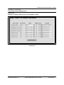
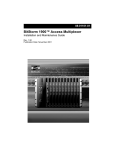
Figure 1-10 shows an Ethernet Port Configuration dialog with the
"Validation Policy" status of "true."
Figure 1-10
Validation Policy in Ethernet Port Configuration
Validation Policy=true
Software Release 2.30
YesWare Applications User’s Guide
08-01016-01
Introducing Visitor-Based Networking and YesWare 1-23
Visitor authentication
YesWare visitor service access is controlled using "authentication" web pages
that require the user to provide the appropriate information before access is
granted to the Internet or other YesWare services.
Authentication page usage
YesWare uses several types of authentication pages. The authentication page
used by a VBN port is determined by the Port Use Context provisioned for the
port (see “VBN billing methods and the Port Use Context” on page 1-15). For
example, ports configured with the credit Port Use Context for Credit-Card
Billing are presented with a "credit" authentication page (credit.vbn), while
ports configured to use Auth Code Billing are presented with an Auth Code
authentication page (authcode.vbn).
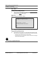
Figure 1-11 shows an example of the default hospitality guest room
authentication page (guest.vbn). Note that "guest.vbn" pages can be
configured to use Auth Codes in addition to billing to the visitor room.
Figure 1-11
Default "guest.vbn" authentication page
Failed visitor authentication
Visitors who fail to successfully authenticate are directed to "service-refusal"
pages that indicate that successful authentication is required for service access.
YesWare enables service providers to customize each authentication page
type, including text and graphic replacement. See “VBN page customization”
on page 1-24 for more information.
Software Release 2.30
YesWare Applications User’s Guide
08-01016-01
1-24 Introducing Visitor-Based Networking and YesWare
VBN web site customization
YesWare provides several methods for service providers to customize how the
VBN web site looks and functions for visitors. The following sections briefly
introduce each of these capabilities. Chapter 10, “Customizing the VBN web
site,” describes the operation and use of these YesWare capabilities.
VBN page customization
The "look-and-feel" of VBN authentication (and service-refusal) pages
determines how the initial connection looks to the visitor. All logos, colors,
and text (in non-functional fields) on these pages can be replaced with
information specific to the service-provider and/or host site. Authentication
pages are modified by retrieving the page from the YWS, and editing the page
using an HTML text editor.
Virtual Concierge
YesWare’s Virtual Concierge feature enables service providers to create a
host-specific site linked to the YWS and filled with free content and
advertising. The VBN visitor can browse the Virtual Concierge for free to
obtain information about local restaurants and host amenities, but will have to
accept the payment terms and conditions to receive Internet access. The
Virtual Concierge function is located in the InterProxy module.
Service-provider branding
YesWare enables service providers to select the name of the service on the web
page that is presented when the visitor connects to the VBN. Service-provider
branding is provided using the Add/Search Branding Setup function, which is
located in the System Setup section of the Port Manager module.
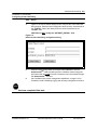
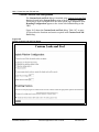
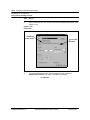
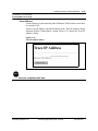
Figure 1-12 shows the default Branding Configuration dialog. The "Home
Page URL" entered in this dialog is used as the "home/splash" page presented
to users after authentication. See “Service-provider home/splash page
configuration” on page 1-25 for more information on VBN home page usage.
Figure 1-12
Default Branding Configuration dialog
Software Release 2.30
YesWare Applications User’s Guide
08-01016-01
Introducing Visitor-Based Networking and YesWare 1-25
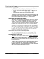
Service-provider home/splash page configuration
YesWare allows the administrator to designate the home/splash page on the
Internet the visitor will see after connecting and authenticating on the VBN.
The URL for the home/splash page is entered in the Branding Configuration
dialog as shown in Figure 1-12 on page 1-24.
Home/splash page settings
YesWare offers the following home/splash page settings to the serviceprovider:
•
•
•
Splash in existing window: The home/splash page appears in the same
browser window that the visitor used to authenticate. In this configuration,
the home/splash page of the service-provider serves as an Internet "portal,"
and will replace any home page configured on the visitor’s computer.
Splash in new window: In this configuration, the home/splash page
appears in a separate browser window after the visitor authenticates.
Visitors see their own home page after the authentication page, while the
service-provider page appears elswhere on the desktop where it can be
viewed or closed by the user.
Splash disabled: In this configuration, no splash page appears. Visitors
see their own home page after the authentication page.
Figure 1-13 shows the Elastic Networks home page that is used as the default
VBN home/splash page. See Chapter 10, “Customizing the VBN web site” for
instructions on how to configure home/splash pages.
Figure 1-13
Elastic Networks home/splash page default
Software Release 2.30
YesWare Applications User’s Guide
08-01016-01
1-26 Introducing Visitor-Based Networking and YesWare
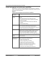
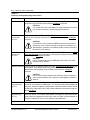
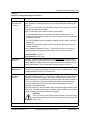
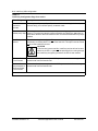
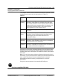
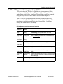
System management and maintenance capabilities
YesWare has a variety of system management and maintenance capabilities.
Table 1-6 lists some of the YesWare modules and functions related to system
management and maintenance.
Table 1-6
YesWare system management and maintenance capabilities
YesWare module
or function
Description
YesWare system
security
YesWare has the following capabilities related to system
security:
• MAC address-based privacy filtering to prevent
unauthorized access to visitor computers connected to
EtherLoop modems
• restricting external network access to the YWS web
interface
• secure password setting
EtherCraft module
EtherLoop modem diagnostics and performance monitoring
tool for monitoring modem status and performance.
EtherCraft can examine all modems or selected modems that
have been provisioned using Port Manager.
SNMP
YesWare supports Simple Network Management Protocol
(SNMP) through a third-party SNMP manager to remotely
monitor and configure YesWare components. SNMP
functions include the capability to generate an event
notification when the YWS link to the facility PMS goes down.
Download Utilities
module
The Download Utilities module is used to upgrade EtherLoop
modem firmware.
Routine system
maintenance and
administration
YesWare has the following capabilities related to routine
system maintenance and administration:
• Creating and deleting users
• System log generation and viewing
• Configuring xNTP (network time protocol)
• Installing and upgrading YesWare modules
• Backing up and restoring the system database
• Backing up the InterProxy configuration
• Shutting down and restarting the YWS via web
Software Release 2.30
YesWare Applications User’s Guide
08-01016-01
Introducing Visitor-Based Networking and YesWare 1-27
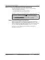
Installing a YesWare VBN system
The process of installing a YesWare VBN system, in broad terms, includes the
following:
5 Install the TCP/IP Ethernet local host LAN/WAN network to support the
YesWare Server connection (if none existing).
6 Install the YesWare VBN infrastructure (EtherLoop or Ethernet).
7 Configure the YWS on an existing local host LAN/WAN.
8 Provision the VBN infrastructure to support YesWare services.
9 Provision site-specific service billing requirements
10 Customize the host site and provision visitor services
This manual covers steps 7 through 10 of the YesWare system installation
process.
Organization of this manual
This document provides procedures for setting up the YesWare Server on the
local host network and for provisioning the YesWare system, as well as for
conducting on-going YesWare system operations and maintenance. In general,
the information is presented in the order in which you will need to use it. The
first part of this manual contains the instructions for using the YesWare
operating system and modules, and for the initial setup of the YesWare system.
The middle part of the document contains the procedures for provisioning sitespecific settings and billing information. The later chapters of the document
cover the YesWare system operations, administration and maintenance tasks.
Software Release 2.30
YesWare Applications User’s Guide
08-01016-01
1-28 Introducing Visitor-Based Networking and YesWare
Software Release 2.30
YesWare Applications User’s Guide
08-01016-01
2-1
YesWare Server operating system and
software modules
2This introduces the purpose and function of the YWS operating system and
software modules.
YesWare terminology / NSS=YesWare or YWS
NSS (Network Services System) was the original name for the suite of software
modules now known as YesWare, and also for the hardware platform containing
the modules now known as the YesWare Server (YWS). This "legacy" name (NSS)
still appears in several places throughout the YesWare modules. Where "NSS"
appears in the modules, assume it to mean either YesWare or YWS, whichever
seems appropriate based on the module context.
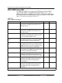
Chapter topic list
This chapter includes the following topics.
Topic
See
YesWare 2.3 software functions and versions
page 2-2
YWS operating system
page 2-3
Using YesWare web-based modules
page 2-4
YesWare web-based modules
page 2-8
Software Release 2.30
YesWare Applications User’s Guide
08-01016-01
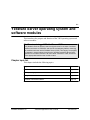
2-2 YesWare Server operating system and software modules
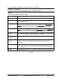
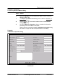
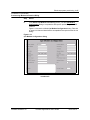
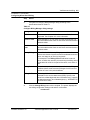
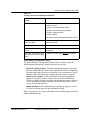
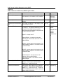
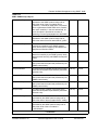
YesWare 2.3 software functions and versions
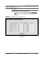
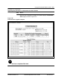
Table 2-1 lists the YesWare operating system and modules and the version
information for the YesWare 2.3 release.
Table 2-1
YesWare module functions and versions
Module name
Function/Description
Elastic Operating
Network (EON)
Operating system for the YesWare Server (YWS). The EON is a 1.49
command-based console interface used to configure the YWS on
the host network and for low-level system diagnostic tests..
NSS Base Software
Web-page structure that supports the YesWare modules.
1.49
InterProxy
Internet protocol (IP) translator and YesWare client router. The
InterProxy module allows YesWare clients with random or nonlocal IP addresses to access LAN and/or WAN services.
2.39
NSS Maintenance
System maintenance functions for YesWare modules and the
YWS. NSS Maintenance functions include password setting,
YesWare system database verification, system log viewing,
YesWare module upgrading, and other functions.
1.49
Conference
Scheduler
Allows YesWare service-providers to schedule and bill conference 1.0
rooms by issuing IP addresses that expire at a provisioned time.
Port Manager
Port provisioning interface for YesWare system. YesWare ports
can be either Ethernet switch ports or EtherLoop modem ports.
2.14
Billing Manager
Provisioning interface for YesWare system billing information.
Functions include setting billing rates and billing system types,
generating end-user authorization codes, and other functions.
2.12
SNMP Proxy Agent
SNMP proxy agent for EtherLoop modems and Ethernet switches 2.11
in the YesWare system. Services SNMP queries to modems from
any external SNMP manager. The YesWare SNMP Proxy Agent
supports SNMPv1 and SNMPv2c protocols.
Modex Daemon
Manages internal communications and controls for EtherLoop
modems in response to SNMP requests from the SNMP Proxy
Agent and control processes from the Downloader Utility.
1.17
EtherCraft
Craft interface to EtherLoop modems. The EtherCraft Utility can
check modem status, check and set modem speeds and training
levels, reset modems, and view modem database information
2.26
Print Services
Allows YesWare visitors to "click-and-print" to a networked printer. 0.04
Download Utilities
EtherLoop modem firmware upgrade utility.
Software Release 2.30
YesWare Applications User’s Guide
YesWare
2.3 Version
2.07
08-01016-01
YesWare Server operating system and software modules 2-3
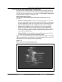
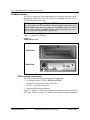
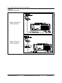
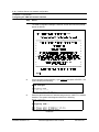
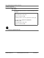
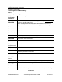
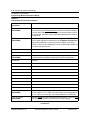
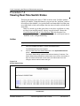
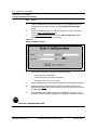
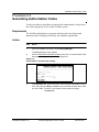
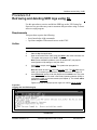
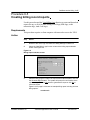
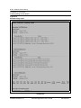
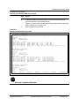
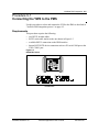
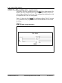
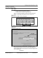
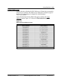
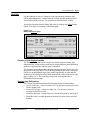
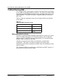
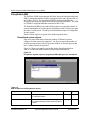
YWS operating system
The YWS operating system is called the Elastic Operating Network (EON).
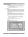
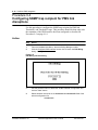
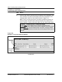
Figure 2-1 shows the"Welcome" screen and prompt you should see after
entering the EON login and password. At this point you can enter the
commands listed in Table 3-2 on page 3-8.
Figure 2-1
EON Welcome screen and command prompt
EON commands
Chapter 3, “YesWare Server host network configuration” describes the
procedures for using the EON commands to configure the YWS on the host
network. Table 3-2 on page 3-8 lists the commands supported by the EON.
Software Release 2.30
YesWare Applications User’s Guide
08-01016-01
2-4 YesWare Server operating system and software modules
Using YesWare web-based modules
All YesWare modules are web-based, and are launched by browsing to the IP
address configured for the YesWare Server ETH 0 network interface.
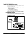
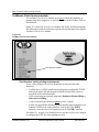
Connecting to the ETH 0 interface
To access the YWS ETH 0 interface, you must have access to the network
where the YWS resides. This can be done with a PC connected over a network,
internetwork, simple passive hub, or through a direct connection to the YWS
ETH 0 interface.
Direct PC connection to ETH 0
To connect a PC directly to the ETH 0 interface, a Category 5 Ethernet crossover
cable must be used and the PC must be configured as a TCP/IP node on the same
LAN and subnet as the ETH 0 interface.
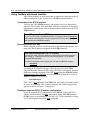
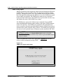
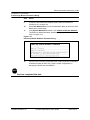
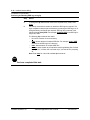
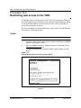
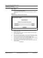
Browsing to the ETH 0 URL
Before using the YesWare web-based modules described in this manual, you
must know the IP address configured for the ETH 0 interface.
YWS default-configured ETH 0 IP address
To access the YWS, use the IP address configured using the console interface
(see Chapter 3, “YesWare Server host network configuration”) or the defaultconfigured ETH 0 address.
The YWS is configured before shipping with the following ETH 0 IP address:
192.168.1.2
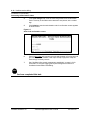
Accessing the YWS main web page is done by specifying the ETH 0
Universal Resource Locator (URL), using a PC with a web browser (Internet
Explorer or Netscape Navigator). The URL must include the ETH 0 IP address
followed by the "nss/" directory, as in the following example (for a YWS at
ETH 0 IP address 10.255.254.2):
10.255.254.2/nss/
If the "/nss/" is not included in the ETH 0 URL, the system will return a denial
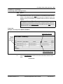
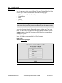
of access. If the ETH 0 URL is entered correctly, the YesWare login dialog
appears as shown in Figure 2-2 on page 2-5:
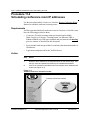
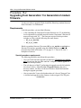
Finding an unknown ETH 0 IP address configuration
If you do not know the IP configuration set for ETH 0, login to the EON
console interface and use the port command to display the ETH 0 settings
(ETH 1 values are also displayed). See Table 3-2, “EON commands” on page
3-8 for a description of the EON port command.
Software Release 2.30
YesWare Applications User’s Guide
08-01016-01
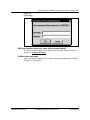
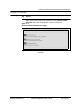
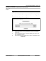
YesWare Server operating system and software modules 2-5
Figure 2-2
Login dialog
YWS web interface login user name and password default
The YWS default-configured user name/password login for the web-based
interface is manager/manager.
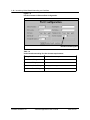
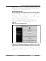
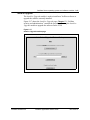
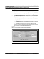
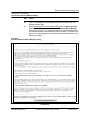
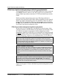
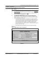
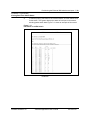
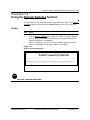
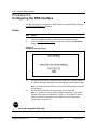
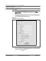
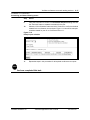
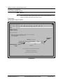
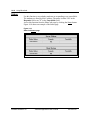
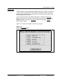
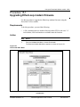
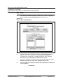
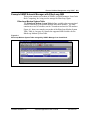
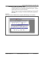
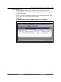
YesWare main web page
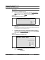
After successfully logging in, the YesWare main page should appear as shown
in Figure 2-3 on page 2-6.
Software Release 2.30
YesWare Applications User’s Guide
08-01016-01
2-6 YesWare Server operating system and software modules
Figure 2-3
YesWare main page
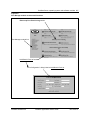
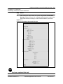
YesWare modules/sections/functions
YesWare modules contain "functions" that execute YesWare operations. These
functions are accessed through HTML links and control buttons on the module
pages. In the Port Manager and NSS Maintenance modules, the module pages
are further divided into "sections."
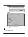
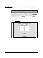
In this document, YesWare module links are italicized, module sections are
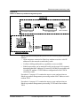
bolded, and module function links and buttons are underlined. Function
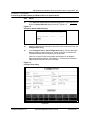
dialogs launched by clicking on the function link or button are in "quotation
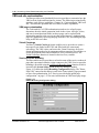
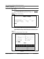
marks." Figure 2-4 on page 2-7 shows the Port Manager module as an
example.
Software Release 2.30
YesWare Applications User’s Guide
08-01016-01
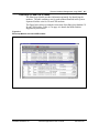
YesWare Server operating system and software modules 2-7
Figure 2-4
Port Manager module sections and functions
EtherLoop Port Provisioning section
Port Manager module link
Add/Search Port List function
"Port Configuration" dialog linked to Add/Search Port List
Software Release 2.30
YesWare Applications User’s Guide
08-01016-01
2-8 YesWare Server operating system and software modules
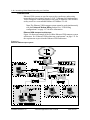
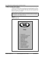
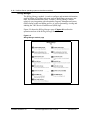
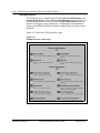
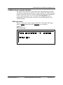
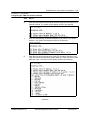
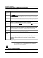
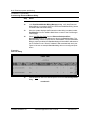
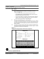
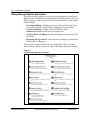
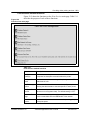
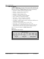
YesWare web-based modules
YesWare web-based modules are used to provision and manage the YesWare
system. Figure 2-5 shows the module links on the YesWare main web page for
this software release. The remainder of this chapter describes the purpose and
function of each of these modules.
On-line Help is available!
Comprehensive on-line Help is available for all YesWare modules by clicking the
Help module link in the YesWare main menu.
Figure 2-5
YesWare module links
Software Release 2.30
YesWare Applications User’s Guide
08-01016-01
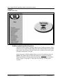
YesWare Server operating system and software modules 2-9
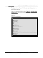
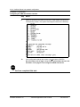
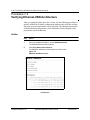
About NSS
The About NSS module contains version and copyright information for the
YesWare software release.
Figure 2-6 shows the About NSS module page.
Figure 2-6
About NSS module page
Software Release 2.30
YesWare Applications User’s Guide
08-01016-01
2-10 YesWare Server operating system and software modules
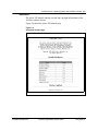
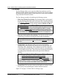
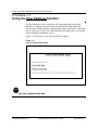
Conference Scheduler
The Conference Scheduler module is used to schedule and bill YesWare
service for Ethernet and/or EtherLoop (ELMo 8 only) equipment located in
facility meeting rooms.
Figure 2-7 shows the Conference Scheduler page. Chapter 11 describes the
operation and use of the Conference Scheduler module.
Figure 2-7
Conference Scheduler module page
Software Release 2.30
YesWare Applications User’s Guide
08-01016-01
YesWare Server operating system and software modules 2-11
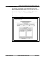
Download Utilities
The Download Utilities module is used to upgrade the firmware in the
EtherLoop modems from either a diskette in the YWS floppy drive or a file
located on the workstation/network.
Figure 2-8 shows the Download Utilities page. Chapter 15 describes the
operation and use of the Download Utilities module.
Figure 2-8
Download Utilities module page
Software Release 2.30
YesWare Applications User’s Guide
08-01016-01
2-12 YesWare Server operating system and software modules
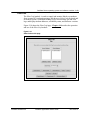
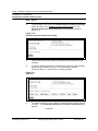
Billing Manager
The Billing Manager module is used to configure and maintain information
used for billing of YesWare end-users, such as the billing system type, rate
table, and user authorization codes. YesWare’s Billing Manager allows
relatively easy integration with a hospitality Property Management System
(PMS) and/or credit-card billing service, as well as generating, viewing and
auditing the YWS Service Detail Record (SDR) logs.
Figure 2-9 shows the Billing Manager page. Chapter 8 describes the
operation and use of the Billing Manager module.
Figure 2-9
Billing Manager module page
Software Release 2.30
YesWare Applications User’s Guide
08-01016-01
YesWare Server operating system and software modules 2-13
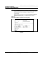
EtherCraft
The EtherCraft module is used to control and monitor EtherLoop modems
from a remote PC/workstation using a Web browser. EtherCraft can check and
set modem speeds, set modem training levels, reset modems, get and clear
logs, and display modem addresses, availability status, and firmware versions.
Figure 2-10 shows the EtherCraft page. Chapter 14 describes the operation
and use of the EtherCraft module.
Figure 2-10
EtherCraft module page
Software Release 2.30
YesWare Applications User’s Guide
08-01016-01
2-14 YesWare Server operating system and software modules
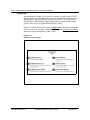
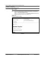
InterProxy
As mentioned in Chapter 1, the InterProxy module is used to route TCP/IPEthernet traffic from YesWare end-users to an external data network such as
the Internet or corporate intranet, regardless of end-user IP configurations.
The InterProxy functionality is most appropriate for networks that support
“guest” users such as a Visitor-Based Network (VBN).
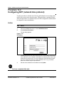
Figure 2-11 shows the InterProxy page. Chapter 4 describes the operation and
use of the InterProxy module, especially how to use the Configure InterProxy
function to set up an InterProxy-VBN system.
Figure 2-11
InterProxy module page
Software Release 2.30
YesWare Applications User’s Guide
08-01016-01
YesWare Server operating system and software modules 2-15
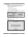
Modex Daemon
The Modex Daemon is the YWS module that controls all direct
communication between the EtherLoop modems and the YWS. It is started at
bootup and runs continuously. The daemon executes functions on the
EtherLoop modems such as the following:
• SNMP get/set commands
• EtherCraft status polling and controls
• EtherLoop modem firmware downloads
The Modex Daemon module contains a button that allows you to start and stop
the daemon without having to re-start the YWS.
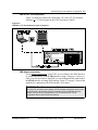
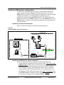
Modex Daemon and ETH 0 / ETH 1
The Modex Daemon can process commands and requests over the ETH 0 or the
ETH 1 interface. In an InterProxy-VBN system, the Modex daemon directs the
processes over the ETH 1 interface. In a "one-armed" EtherLoop OAM&P system,
the Modex daemon directs the processes over the ETH 0 interface.
The Set ModeX daemon information function in the System Maintenance section
of the NSS Maintenance module contains a pull-down menu to change the daemon
setting to either ETH 0 or ETH 1. See “NSS Maintenance” on page 2-16.
Figure 2-12 shows the Modex Daemon page.
Figure 2-12
Modex Daemon module page
Software Release 2.30
YesWare Applications User’s Guide
08-01016-01
2-16 YesWare Server operating system and software modules
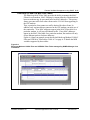
NSS Maintenance
The NSS Maintenance module is divided into Password Maintenance and
System Maintenance sections. Password Maintenance functions allow you
to maintain passwords and user accounts. System Maintenance functions
include verifying the system architecture, validating the modem database,
setting up the SNMP and Modex Daemon configurations, and other system
functions.
Figure 2-13 shows the NSS Maintenance page.
Figure 2-13
NSS Maintenance module page
Software Release 2.30
YesWare Applications User’s Guide
08-01016-01
YesWare Server operating system and software modules 2-17
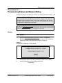
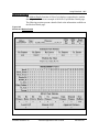
Print Services
The Print Services module gives YesWare visitors the ability to print to a
networked printer such as one located behind the front desk of a hotel or an
office services retail store.
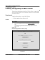
Figure 2-14 shows the Print Services page. Chapter 12, “Providing visitor
printing services” describes the operation and use of the Print Services
module.
Figure 2-14
Print Services module page
Software Release 2.30
YesWare Applications User’s Guide
08-01016-01
2-18 YesWare Server operating system and software modules
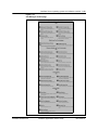
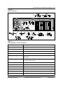
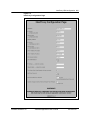
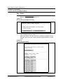
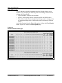
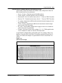
Port Manager
The Port Manager allows you to provision EtherLoop modems as well as
Ethernet switches and their associated ports. From here, you can also configure
the subnet mask, gateway address for the InterProxy-VBN system, branding
setup, and check-in/check-out times.
The Port Manager module is divided into the following sections:
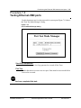
• EtherLoop Modem Provisioning: The functions in this section control
the provisioning of the EtherLoop CO/SE and CPE/CE modem databases.
The Find New Modems function automatically detects all modems on the
same LAN segment as the YWS network interface (ETH 0 or ETH 1).
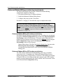
Find New Modems and ETH 0 / ETH 1
The Find New Modems function automatically detects all modems on the same
LAN segment as the YWS network interface (ETH 0 or ETH 1). To detect
modems in an InterProxy-VBN system, the Modex Daemon must be set to
ETH 1. In a "one-armed" EtherLoop OAM&P system, the Modex Daemon must
be set to ETH 0. See “Modex Daemon and ETH 0 / ETH 1” on page 2-15.
•
Ethernet Switch and Port Provisioning: The functions in this section
control the provisioning of the Ethernet switch and port databases.
Ethernet Switches and InterProxy
Ethernet switches and ports can only be provisioned for InterProxy (ETH 1) VBN
systems.
•
System Setup: The functions in this section set up the branding
configuration, which identifies the Internet Service Provider (ISP) and
Home Page URL "splash page" that is displayed to YesWare end-users.
Customizing the branding setup is required in order for your splash page
to be presented to guest users. This section also includes the functions to
set up the gateway and subnet mask used by provisioned Ethernet
switches.
Port Manager / System Setup Gateway and Subnet Mask
System Setup Gateway=InterProxy ETH 1 IP address
System Setup Subnet Mask=InterProxy ETH 1 Network Mask
The Gateway Address used by the YesWare system is the same address as the
InterProxy ETH 1 IP address. The Subnet Mask address used by the YesWare
system is the same address as the ETH 1 network mask address.
•
System Tools: The functions in this section handle port testing, tracing
user activity, and customizing the YesWare end-user interface.
Figure 2-15 on page 2-19 shows the Port Manager page.
Software Release 2.30
YesWare Applications User’s Guide
08-01016-01
YesWare Server operating system and software modules 2-19
Figure 2-15
Port Manager module page
Software Release 2.30
YesWare Applications User’s Guide
08-01016-01
2-20 YesWare Server operating system and software modules
SNMP Proxy Agent
EtherLoop modems do not support the Simple Network Management Protocol
(SNMP) directly. However, the modems do support the proprietary Modex
protocol. Through the SNMP Proxy Agent and the Modex Daemon modules,
the YWS implements both protocols and thus serves as the SNMP proxy agent
for the EtherLoop modems. The SNMP proxy agent process is started at
bootup and runs continuously. The SNMP Proxy Agent module can start, stop,
and monitor the status of the SNMP Proxy Agent.
The SNMP proxy agent on the YWS accepts commands from an SNMP
Network Management Station (NMS) running a third-party SNMP manager
such as HP OpenView. The SNMP proxy agent takes the commands and
retrieves statistics about the operation and performance of EtherLoop modems
attached to the system using the Modex Daemon. The SNMP proxy agent can
also retrieve basic up/down status of Ethernet switches attached to the YWS.
Setting SNMP traps
The Set SNMP Information in the System Maintenance section of the NSS
Maintenance module configures the EtherLoop modems to generate SNMP traps to
a particular IP address.
Figure 2-16 shows the SNMP Proxy Agent page. Appendix A describes
remote YesWare management using SNMP.
Figure 2-16
SNMP Proxy Agent module page
Software Release 2.30
YesWare Applications User’s Guide
08-01016-01
YesWare Server operating system and software modules 2-21
Install or Upgrade
The Install or Upgrade module is used to install new YesWare software or
upgrade the software currently installed.
Figure 2-17 shows the Install or Upgrade page. Chapter 13, “YesWare
security and administration” contains the procedure for using the Install or
Upgrade module to upgrade the software on the YWS.
Figure 2-17
Install or Upgrade module page
Software Release 2.30
YesWare Applications User’s Guide
08-01016-01
2-22 YesWare Server operating system and software modules
Software Release 2.30
YesWare Applications User’s Guide
08-01016-01
SECTION II
YESWARE INSTALLATION AND CONFIGURATION
Software Release 2.30
Software Release 2.30
YesWare Applications User’s Guide
08-01016-01
3-1
YesWare Server host network
configuration
3-
This chapter describes the methods for connecting to the YesWare Server
(YWS) and using the Elastic Operating Network (EON) operating system to
configure the YWS on the host network.
Chapter topic list
This chapter includes the following topics.
Topic
See
YesWare Server
page 3-2
YesWare Server console connection methods
page 3-4
YesWare Server console interface
page 3-7
Chapter task list
This section includes the following tasks.
Procedure
Task
See
3-1
Configuring the YWS host network interface
page 3-9
3-2
Setting the YWS date and time
page 3-13
3-3
Setting the DNS nameserver(s) for the YWS
page 3-15
Software Release 2.30
YesWare Applications User’s Guide
08-01016-01
3-2 YesWare Server host network configuration
YesWare Server
The YWS is used to provision and manage services to the YesWare system
infrastructure and clients. The YWS resides as a standard "host" on a local
TCP/IP Ethernet host network.
YesWare terminology - ETH 0 and ETH 1
The YWS contains two Ethernet 10Base-T network interface cards (NICs) called
ETH 0 and ETH 1 (see Figure 3-2 on page 3-3). The ETH 0 interface connects the
YWS to the host network. The ETH 1 interface connects YesWare clients to the
YWS for access to YesWareís InterProxy services.
Figure 3-1 shows the YWS unit.
Figure 3-1
YesWare Server unit
Front View
Back View
YWS functional components
The YWS unit has the following functional components:
• two Ethernet 10Base-T NICs (ETH 0 and ETH 1)
• two RS-232 serial ports (COM1 and COM2)
• 110/120 V AC power connector
• monitor and keyboard connectors
Figure 3-2 on page 3-3 shows the component connections on the back of the
YWS unit. Table 3-1 on page 3-3 describes the function of each component.
Software Release 2.30
YesWare Applications User’s Guide
08-01016-01
YesWare Server host network configuration 3-3
Figure 3-2
YWS connections
Table 3-1
YWS component connector functions
YWS Connector
Description/Function
Primary Power Switch
Controls power to unit. Secondary switch on front not used.
AC Power Connector
110/120 V AC input.
Keyboard
Standard PS2 keyboard interface.
USB Connector (not used)
Universal Serial Bus (USB) device interface.
COM 1
RS232 serial interface to Property Management System (PMS) or
serial printer.
COM 2
RS232 serial interface for VT-100 terminal (or terminal emulator) used
with YWS console interface.
Mouse (not used)
PS2 mouse interface.
Printer Port (not used)
Parallel printer interface.
Monitor
15-pin D-Sub monitor interface for VGA, SVGA or later model.
Modem (not used)
Analog modem.
ETH 0
Ethernet 10Base-T interface to YWS host network (LAN or WAN).
ETH 1
Ethernet 10Base-T interface to YesWare’s InterProxy clients.
Software Release 2.30
YesWare Applications User’s Guide
08-01016-01
3-4 YesWare Server host network configuration
YesWare Server console connection methods
The YWS "console" consists of connectors located on the back of the YWS
used to access the EON interface. You can connect to the YWS console using
any one of the following methods:
• keyboard (PS2) and monitor (VGA or better)
• VT-100 terminal emulation program on a PC with a serial communications
port and a null-modem cable
• VT-100 terminal with a null-modem cable
• telnet from a PC to the YWS ETH 0 interface
The following sections illustrate these YWS console connection methods.
YWS keyboard/monitor connections
Figure 3-3 shows the method for connecting a keyboard/monitor combination
to the YWS.
Figure 3-3
YWS keyboard/monitor connections
Software Release 2.30
YesWare Applications User’s Guide
08-01016-01
YesWare Server host network configuration 3-5
YWS PC/VT-100 connection
Figure 3-4 shows the method for connecting a PC with a VT-100 terminal
emulator or a VT-100 terminal to the YWS serial port (COM 2).
Figure 3-4
YWS PC or VT-100 terminal console connection
YWS telnet connection
For the initial configuration of the YWS, you can telnet to the EON interface
by connecting directly to the ETH 0 interface using a Category 5 cross-over
cable. You can also telnet to the EON over an existing network connection to
the ETH 0 interface to change EON settings. Figure 3-5 on page 3-6 shows the
methods for connecting to the EON interface over telnet.
CAUTION - Possible network conflict
The YWS ETH 0 interface has a default TCP/IP address configuration which could
conflict with the host network. DO NOT connect the ETH 0 interface to a host
network until you have re-configured the ETH 0 interface with a TCP/IP
configuration that is valid for the host network.
Software Release 2.30
YesWare Applications User’s Guide
08-01016-01
3-6 YesWare Server host network configuration
Figure 3-5
YWS telnet connections
Telnet / Direct PC-toYWS connection
Telnet / Network-toYWS connection
Software Release 2.30
YesWare Applications User’s Guide
08-01016-01
YesWare Server host network configuration 3-7
YesWare Server console interface
The YWS console interface is called the Elastic Operating Network (EON).
The EON is a command-based interface used to configure the YWS on the host
network. The EON can also be used to conduct low-level system diagnostics
such as "ping" tests and to view route-table and ETH 0/ETH 1 port
assignments. The EON interface can only be accessed through the YWS
console interface.
EON login default
Figure 3-6 shows the "login" prompt of the EON. The default YWS login
name is admin and the password is etherloop (case-sensitive).
Figure 3-6
EON login prompt
Software Release 2.30
YesWare Applications User’s Guide
08-01016-01
3-8 YesWare Server host network configuration
EON commands
Table 3-2 lists the EON commands used to set up the YWS.
Table 3-2
EON commands
Command
Function
Syntax
help
Displays this list of EON commands.
help
route
Display YWS routing table.
route
port
Display YWS ETH 0 and ETH 1 port settings.
port
ping
Test basic communications between the YWS, ping
client computers, and the host network.
passwd
Change admin user password. For security
purposes, use this command to change the
default password after the first login.
passwd
configure
Configure the ETH 0 interface network IP
address, gateway, YWS host name (see
nameserver command below), and time
zone.
configure
Specify the name server the YWS will use. If
the YWS will use the Domain Name System
(DNS), the YWS must have a valid DNS name
server and host name.
nameserver
(displays current nameserver settings)
date
Display and set system date and time
date
reboot
Shut down and re-start the YWS. Always use reboot
this command to re-boot the YWS. Never use
only the YWS power switch for a re-boot, as an
uncontrolled shutdown/re-start could corrupt
the EON software.
shutdown
Shut down the YWS. Always use this command shutdown
to shut down the YWS. Never use only the
YWS power switch for a shutdown, as an
uncontrolled shutdown could corrupt the EON
software.
exit
Close the EON Configuration Manager and exit exit
to the EON login prompt. To prevent
unauthorized access to the YWS, always use
this command after EON configuration tasks
are done.
timezone
Change the time zone used by the YWS.
nameserver
(optional)
Software Release 2.30
See Procedure 3-1 on page 3-9.
nameserver [front/last/del]
(adds or deletes nameservers)
timezone
YesWare Applications User’s Guide
08-01016-01
YesWare Server host network configuration 3-9
Procedure 3-1
Configuring the YWS host network interface
This procedure explains how to configure the YWS host network interface
(ETH 0) using the EON interface.
Requirements
To perform this procedure, you need the following:
•
valid TCP/IP configuration for the YWS ETH 0 network interface,
including the following:
— IP address
— network mask (subnet) address
— network gateway address
•
•
•
host name for the YWS
DNS nameserver IP address (if applicable)
time zone information for the YWS host network
Action
Step
Action
1
Connect to the YesWare console using one of the methods described in
“YesWare Server console connection methods” on page 3-4.
2
Connect the YWS power plug to an appropriate power source, and flip the
power switch ON.
After the YWS completes its power-on initialization sequence, the YesWare
login prompt should appear as follows:
3
Enter the YWS login name and password.
—continued—
Software Release 2.30
YesWare Applications User’s Guide
08-01016-01
3-10 YesWare Server host network configuration
Procedure 3-1 (continued)
Configuring the YWS host network interface
Step
Action
The EON Configuration Manager "welcome" screen and command prompt
appear as follows:
4
At the command prompt (NSS#>), type configure and press <ENTER>. The
system displays the following:
5
Enter the valid host network IP address assigned to the YWS ETH 0 network
interface. The system should appear similar to the following:
—continued—
Software Release 2.30
YesWare Applications User’s Guide
08-01016-01
YesWare Server host network configuration 3-11
Procedure 3-1 (continued)
Configuring the YWS host network interface
Step
Action
6
Enter the valid network mask (subnet) address assigned to the YWS ETH 0
network interface. The system should appear similar to the following:
7
Enter the valid gateway IP address assigned to the YWS ETH 0 network
interface. The system should appear similar to the following:
8
Enter the host name assigned to the YWS ETH 0 network interface. If the
YWS will use the Domain Name System (DNS), the YWS must have a valid
DNS host name. The system should appear similar to the following:
—continued—
Software Release 2.30
YesWare Applications User’s Guide
08-01016-01
3-12 YesWare Server host network configuration
Procedure 3-1 (continued)
Configuring the YWS host network interface
Step
Action
9
Select the time zone from the list in which the YWS resides, and enter the
corresponding number. The system should appear similar to the following:
10
If the configuration settings are correct, type y and press <ENTER>.
Go to Procedure 3-2 on page 3-13 to set the system date and time, and
Procedure 3-3 on page 3-15 to configure the DNS nameserver.
STOP
You have completed this task.
Software Release 2.30
YesWare Applications User’s Guide
08-01016-01
YesWare Server host network configuration 3-13
Procedure 3-2
Setting the YWS date and time
This procedure explains how to use the EON date command to set the date and
time for the YWS.
Requirements
To perform this procedure, you need the following:
•
a connection to the YWS ETH 0 network interface using one of the
methods described in “YesWare Server console connection methods” on
page 3-4. host name for the YWS
Action
Step
Action
1
Login to the YWS (the steps for logging into the YWS are presented in
Procedure 3-1 on page 3-9).
2
At the command prompt (NSS#>), type date and press <ENTER>. The
system should appear similar to the following:
3
Type y and press <ENTER>. The system should appear similar to the
following:
—continued—
Software Release 2.30
YesWare Applications User’s Guide
08-01016-01
3-14 YesWare Server host network configuration
Procedure 3-2 (continued)
Setting the YWS date and time
Step
Action
4
Enter the system date and local time. The system should appear similar to
the following:
STOP
You have completed this task.
Software Release 2.30
YesWare Applications User’s Guide
08-01016-01
YesWare Server host network configuration 3-15
Procedure 3-3
Setting the DNS nameserver(s) for the YWS
Use this procedure to identify the DNS nameserver used by the YWS. The
EON nameserver command can be used to display, add or delete the IP
address(es) of the DNS nameserver(s) supporting the YWS. Nameserver
addresses can be added to the beginning or the end of the nameserver list. This
procedure describes each of these command capabilities.
Requirements
To perform this procedure, you need the following:
•
•
a connection to the YWS ETH 0 network interface using one of the
methods described in “YesWare Server console connection methods” on
page 3-4. host name for the YWS
a valid DNS nameserver IP address
Valid host and domain name required
The YWS must also have a valid DNS host/domain name (host.domain.domain)
defined using the EON configure command. See Procedure 3-1 on page 3-9.
Action
Step
Action
1
Login to the YWS (the steps for logging into the YWS are presented in
Procedure 3-1 on page 3-9).
2
To display the existing nameserver addresses, type nameserver at the
command prompt (NSS#>), and press <ENTER>. The system should appear
similar to the following:
—continued—
Software Release 2.30
YesWare Applications User’s Guide
08-01016-01
3-16 YesWare Server host network configuration
Procedure 3-3 (continued)
Setting the DNS nameserver(s) for the YWS
Step
Action
3
To add a nameserver to the beginning of the list of existing nameserver
addresses, type nameserver front at the command prompt (NSS#>), and
press <ENTER>. The system should appear similar to the following:
4
To add a nameserver to the end of the list of existing nameserver addresses,
type nameserver last at the command prompt (NSS#>), and press
<ENTER>. The system should appear similar to the following:
5
To remove a nameserver from the list of existing nameserver addresses, type
nameserver del at the command prompt (NSS#>), and press <ENTER>. The
system should appear similar to the following:
6
Configure the InterProxy to support the VBN as described in Chapter 4,
“InterProxy VBN configuration.”
STOP
You have completed this task.
Software Release 2.30
YesWare Applications User’s Guide
08-01016-01
4-1
InterProxy VBN configuration
4-
This chapter presents procedures to configure the InterProxy module to
support a Visitor-Based Network (VBN) system.
Chapter topic list
This chapter includes the following topics.
Topic
See
InterProxy module functions
page 4-2
InterProxy VBN system configuration
page 4-3
Chapter task list
This chapter includes the following tasks.
Procedure
Task
See
4-1
Configuring the InterProxy network connection
page 4-9
Software Release 2.30
YesWare Applications User’s Guide
08-01016-01
4-2 InterProxy VBN configuration
InterProxy module functions
The InterProxy module contains the following functions:
• Configure InterProxy
• Backup InterProxy
• Configure Remote Access
• Virtual Concierge
• Configure Proxy IP Address
• TFTP Daemon Manager
Of these InterProxy module functions, this chapter covers only the Configure
InterProxy function used to configure the YWS to support the visitor
computers on the VBN. The following sections briefly describe the purpose of
each of the remaining functions, and cross-references to the location in this
document covering each function.
Backup InterProxy
This function is used to backup the existing InterProxy configuration. This
backup function is separate from the system backup function in the NSS
Maintenance module. See Procedure 13-12 on page 13-27, “Backing up the
InterProxy configuration,” for the procedure to use this function.
Configure Remote Access
This function is used to restrict remote access to the YWS Web interface. See
Procedure 13-2 on page 13-6, “Restricting web access to the YWS,” for the
procedure to use this function.
Virtual Concierge
This function is used to configure the IP address of a Web site that contains free
content available to the VBN visitors at the YWS host site. See Chapter 10,
“Customizing the VBN web site” for more information on the operation and
use of this function.
Configure Proxy IP Address
This function is used to configure the IP address of a system that uses HTTP
Proxy to "reverse-proxy" into the YWS. Reverse-proxy is used to access the
Web interfaces of Ethernet switches in the VBN when upgrading the switch
firmware. See Procedure 7-5 on page 7-22, “Upgrading Ethernet-VBN switch
firmware using TFTP and HTTP Proxy” for more information.
TFTP Daemon Manager
This function is used to start and stop the TFTP Daemon Manager that
supports Trivial File Transfer Protocol (TFTP) on the YWS. TFTP is used to
transfer switch firmware upgrade files to the YWS. See Procedure 7-5 on page
7-22, “Upgrading Ethernet-VBN switch firmware using TFTP and HTTP
Proxy” for more information.
Software Release 2.30
YesWare Applications User’s Guide
08-01016-01
InterProxy VBN configuration 4-3
InterProxy VBN system configuration
The InterProxy function accepts and routes TCP/IP Ethernet traffic from
visitor computers connected through a VBN infrastructure to the YWS
ETH 1 interface. InterProxy-VBN clients can connect to the network through
an EtherLoop, Ethernet, or combined EtherLoop/Ethernet system
infrastructure. Upon reaching the ETH 1 interface, the YWS switches the
InterProxy traffic from the ETH 1 interface over to the ETH 0 interface. The
ETH 0 interface connects to an external data network such as the Internet or
corporate intranet.
InterProxy functional architecture
Figure 4-1 shows the InterProxy-VBN functional architecture.
Figure 4-1
InterProxy-VBN functional architecture
YesWare VBN
Visitor Computers
YWS Host Network
RJ-45
10Base-T
Wide Area
Network
RJ
45
EtherLoop or Ethernet
Switch/Hub
LAN/WAN Term.
(To Network Router)
InterProxy
RJ
-45
YWS Eth0
10/100Base-T
YesWare
Server
YWS Eth1
10/100Base-T
RJ
45
InterProxy limitations for visitor computers
InterProxy-based internetwork access has the following limitations:
• Visitors who have assigned IP addresses that are in the same subnet as the
ETH 0 IP address will not receive internetwork access (with the exception
of IP addresses provisioned using the Conference Scheduler module).
• Visitors that have a home page designated with the "don’t use proxies"
feature enabled for the home page will not receive internetwork access.
• All InterProxy-VBN clients must reside on the same LAN segment as the
YWS ETH 1 interface. InterProxy-VBN client traffic cannot pass through
a LAN router or bridge before reaching the ETH 1 connection.
Software Release 2.30
YesWare Applications User’s Guide
08-01016-01
4-4 InterProxy VBN configuration
InterProxy configuration procedure
The system administrator must configure the InterProxy ETH 1 interface for
VBN routing. This is done using the InterProxy Configuration Page
launched using the Configure InterProxy function.
Procedure 4-1 on page 4-9 contains the steps required to configure the
InterProxy/ETH 1 interface to serve a VBN system..
CAUTION - Potential network outage
The InterProxy attempts to serve as the gateway for any network to which it is
connected. If the InterProxy ETH 1 port is accidentally connected to the host
network instead of the visitor network, the InterProxy will conflict with the host
network routers and likely cause a network outage.
InterProxy Configuration Page
Figure 4-2 on page 4-5 shows an example of the "InterProxy Configuration
Page." Table 4-1 on page 4-6 lists the settings and describes the information
required to complete form for the InterProxy system configuration.
Recommended InterProxy / ETH 1 configuration settings
Elastic Networks’ guidelines for configuring settings for the ETH 1 IP address,
network mask, and DHCP range described in Table 4-1 on page 4-6.
These guidelines can help ensure that ample addresses are available and that
addresses do not conflict, especially when the system is installed in a corporate
Intranet.
These guidelines are intended only as suggestions. Your system administrator
may develop an addressing scheme that better fits your particular system
management configuration.
Software Release 2.30
YesWare Applications User’s Guide
08-01016-01
InterProxy VBN configuration 4-5
Figure 4-2
InterProxy Configuration Page
Software Release 2.30
YesWare Applications User’s Guide
08-01016-01
4-6 InterProxy VBN configuration
Table 4-1
InterProxy Configuration Page form entries
Form Entry
Hostname
Description
The host name and domain name assigned to the InterProxy. This entry is typically
configured using the EON console interface configure command.
CAUTION
If an invalid host name is submitted for a system that requires service
from a DNS nameserver, access using DNS will be lost.
IP Address primary port
(ETH 0)
IP address for the YWS ETH 0 interface. This entry must be valid for the host
network, and is typically configured using the EON console interface configure
command.
CAUTION
If you submit a new IP address for ETH 0, users will not be able to
access any of the YesWare modules using the old IP address. Any
administrators, operators of a YesWare system must be informed of
the new ETH 0 IP address.
Network Mask primary port
(ETH 0)
Network mask (also called the subnet mask) for the YWS ETH 0 interface. This
entry must be valid for the host network, and is typically configured using the EON
console interface configure command.
CAUTION
Loss of communication with the ETH 0 port will result if an invalid
network mask is entered.
Gateway Address Network gateway IP address used by the YWS. This entry must be valid for the
host network. The gateway address is typically obtained from the host network
administrator and configured using the EON console interface configure
command.
CAUTION
Loss of communication between the InterProxy and the Internet (or
main corporate network) may result if an invalid gateway address is
entered.
IP Address secondary port
(ETH 1)
Enter the IP address selected for the InterProxy ETH 1 port. This is the physical
connection to the InterProxy-VBN system. The YesWare system administrator can
assign any subnet IP address, provided that it meets the standard subnet criteria
as defined by Internet RFC 950 (1985). Elastic Networks recommends using the
default 10.237.1.1.
Network Mask secondary port
(ETH 1)
Enter the network mask for the InterProxy ETH 1 port. This mask is used by the
InterProxy subnet. Your network administrator can assign any valid subnet mask.
Elastic Networks suggests using 255.0.0.0, which is a Class A subnet address, to
ensure the network will not run out of network mask addresses.
—continued—
Software Release 2.30
YesWare Applications User’s Guide
08-01016-01
InterProxy VBN configuration 4-7
Table 4-1
InterProxy Configuration Page form entries
Form Entry
DHCP Address
Pool Start and
Pool End
Description
If the InterProxy needs to support DHCP (Dynamic Host Configuration Protocol) for
client computers, select and enter the pool of DHCP addresses available on the
InterProxy.
Note: If you do not specify a DHCP address range, then all “guest” PCs must be
configured with static IP addresses.
DHCP IP addresses must meet the following requirements:
• The DHCP address group must fall within the port's IP address pool. The
available IP address pool is based both on the IP address and the subnet mask
configured for the port.
• The host IP address and the broadcast IP address cannot be within the DHCP
address pool.
• The DHCP range cannot overlap any other equipment (Ethernet switches or
CO/CPE modems)
Given an ETH 1 IP address of 10.237.1.1 and network mask of 255.0.0.0 (as
suggested earlier), the following DHCP address values are recommended:
DHCP Pool Start: 10.237.1.2
DHCP Pool End:10.237.3.254
DNS Server
Address
This entry is typically configured using the EON nameserver command. If the
InterProxy is going to use a DNS server to resolve names, you must provide the
valid IP address of a DNS name server. Obtain the DNS server address from your
network administrator. (The universal DNS number is 199.191.128.104.)
User
Authentication
This option enables the YWS to require end-users to bring up a Web browser and
view an external page before passing any traffic through. The default is Off. If using
the Billing Manager module, turn this option On.
IP Address network to
exclude
This is optional. Occasionally a single physical network will host multiple logical
networks (IP address spaces). In some cases, the ETH 1 port connects to this type
of network. To handle this situation, the network exclusion option allows you to
specify one (and only one) additional logical subnet which the system identifies as
‘local’ to the InterProxy. This avoids interference in this IP address space and
prevents network conflicts caused by the InterProxy attempting to proxy for
machines in this address space.
In this field, specify any host IP address valid for the second logical subnet (on the
ETH 1 side). This field, together with the network mask you enter in the next field,
is used to identify the network to exclude (or bypass).
CAUTION
Once you configure the network exclusion option, users with foreign
addresses may gain access to network resources (such as printer, file
servers, etc.).
—continued—
Software Release 2.30
YesWare Applications User’s Guide
08-01016-01
4-8 InterProxy VBN configuration
Table 4-1
InterProxy Configuration Page form entries
Form Entry
Network Mask network to
exclude
Description
This is optional. If you specify an IP address for the second logical subnet (see
previous field), you must also specify a network mask.
Check if network Turn this option on if the network has end-systems using proxy address resolution
utilizes proxy arps protocol. This prevents network conflicts caused by the InterProxy attempting to
serve traffic meant for the local network router. It is recommended the Proxy Arp is
enabled.
InterProxy
Service
The default setting for this field is Off to prevent a network outage caused by
accidentally connecting the ETH 1 port to the host LAN. This option must be turned
On to provide InterProxy service.
CAUTION
If this function is not turned On, InterProxy service will not function.
Users on the ETH 1 system will be prevented from routing through
the InterProxy and gaining access to the ETH 0 host network.
Remove Routes
From Firewall
The amount of time (in seconds) the YWS system waits before removing an
unused route from the firewall rules.
Number of
Subprocesses to
Remove Routes
From Firewall
The number of subprocess cycles that the YWS system waits before removing an
unused route from the firewall rules.
—END-OF-TABLE—
Software Release 2.30
YesWare Applications User’s Guide
08-01016-01
InterProxy VBN configuration 4-9
Procedure 4-1
Configuring the InterProxy network connection
Use this procedure to configure the InterProxy/ETH 1 interface to serve a
VBN system.
Action
Step
Action
1
Using a PC web browser, browse to the IP address configured for the ETH 0
interface, and login to the YWS.
2
From the YesWare main menu, select the InterProxy module and select the
Configure InterProxy function.
The "InterProxy Configuration Page" is displayed as shown in Figure 4-2 on
page 4-5.
3
Enter the InterProxy form entry items as described in Table 4-1 on page 4-6
according to your system requirements. Be sure to set InterProxy service
radial button to "on".
4
Record the values entered on the "InterProxy Configuration Page" according
to local office procedures. These values may be needed for some of the
provisioning tasks performed later.
5
Click Submit to save the InterProxy settings.
CAUTION - This step overwrites previous InterProxy values
All prior InterProxy configuration values will be overwritten. If you want to
discard the settings, click a module on the main menu (without clicking the
submit button) and the InterProxy settings will not be submitted.
Note: Once you have configured the InterProxy, you should backup your
configuration on diskette and store the backup in a safe place. (See “Backing
up the InterProxy configuration” on page 13-27.)
6
Continue with the provisioning process by configuring the YWS as the VBN
gateway and Network Services System switch (see Chapter 5).
STOP
You have completed this task.
Software Release 2.30
YesWare Applications User’s Guide
08-01016-01
4-10 InterProxy VBN configuration
Software Release 2.30
YesWare Applications User’s Guide
08-01016-01
5-1
VBN gateway and Network Services
System switch configuration
5-
This chapter presents procedures to configure the YWS to serve as the gateway
for the VBN system.
Chapter topic list
This chapter includes the following topics.
Topic
See
Configuration requirements
page 5-2
Chapter task list
This chapter includes the following tasks.
Procedure
Task
5-1
Provisioning the VBN gateway and Network Services page 5-3
System switch
Software Release 2.30
YesWare Applications User’s Guide
See
08-01016-01
5-2 VBN gateway and Network Services System switch configuration
Configuration requirements
The YWS ETH 1 interface is the "gateway" to the external network used by
the EtherLoop modems and/or Ethernet switches in the VBN. The "Network
Services System" is the switch supporting the VBN system of EtherLoop
modems and/or Ethernet switches. The system administrator must provision
the ETH 1 interface as the Network Services System switch and also as the
gateway serving the VBN. This process includes the following tasks:
• The system administrator must provision the ETH 1 interface as the
single-port Network Services System switch and configure the ETH 1 port
• The InterProxy ETH 1 IP address that was defined using the InterProxy
Configuration Page (see Chapter 4) must be defined as the gateway
address for the VBN.
• The InterProxy ETH 1 network mask that was defined using the
InterProxy Configuration Page (see Chapter 4) must be defined as the
subnet mask for the VBN.
Procedure 5-1 on page 5-3 contains the steps required to complete these tasks.
Software Release 2.30
YesWare Applications User’s Guide
08-01016-01
VBN gateway and Network Services System switch configuration 5-3
Procedure 5-1
Provisioning the VBN gateway and Network Services
System switch
Use this procedure to provision the InterProxy ETH 1 interface as VBN
gateway and Network Services System switch.
Note: See Chapter 7, “Provisioning the Ethernet-VBN switches and ports”
for more information about the general requirements for Ethernet switch
provisioning and the Network Services System function in an EthernetVBN architecture.
Action
Step
Action
1
From the YesWare Main Menu, choose Port Manager.
The Port Manager menu appears.
2
In the Ethernet Switch and Port Provisioning section, select Add/Search
Switch Address.
3
Click the Search button in the Switch Address Configuration dialog.
4
To prevent entering a duplicate IP address, determine if the InterProxy
ETH 1 IP address has been pre-provisioned. If the ETH 1 IP address has not
been provisioned, add the address as shown in Figure 5-1.
Figure 5-1
Switch Address Configuration dialog with default ETH 1 IP address
—continued—
Software Release 2.30
YesWare Applications User’s Guide
08-01016-01
5-4 VBN gateway and Network Services System switch configuration
Procedure 5-1 (continued)
Provisioning the VBN gateway and Network Services System switch
Step
Action
5
In the System Setup section, select Add/Search Gateway Address.
The Gateway Address Configuration dialog appears as shown in Figure 5-2
on page 5-4.
Figure 5-2
Gateway Address Configuration dialog
6
Enter the ETH 1 IP address in the Gateway Address field, and click Add.
7
In the System Setup section, select Add/Search Subnet Mask.
The Subnet Mask Configuration dialog appears as shown in Figure 5-3.
Figure 5-3
Subnet Mask Configuration dialog
8
Enter the Subnet Mask and click Add. This mask must be the same as the
"Network Mask" that was configured for the ETH 1 secondary port in the
"InterProxy Configuration Page."
—continued—
Software Release 2.30
YesWare Applications User’s Guide
08-01016-01
VBN gateway and Network Services System switch configuration 5-5
Procedure 5-1 (continued)
Provisioning the VBN gateway and Network Services System switch
Step
Action
9
In the Ethernet Switch and Port Provisioning section, select Add/Search
Switch Information.
10
Select the switch address corresponding to ETH 1, and click the edit link or
the Search button to launch the Switch Configuration dialog.
11
In the Switch Configuration dialog, provision the ETH 1 IP address as the
"Network Services System" switch. An example configuration is shown in
Figure 5-4. Note the following about the Network Services System switch
configuration:
•
The Network Services System has no "Parent" switch and no "Installed
High Speed Ports."
•
The "Gateway Address" of the Network Services System is identical to
the "IP address."
•
The "Enabled" field must be set to "true" for the switch to function.
Table 5-1 on page 5-6 contains the recommended settings for the Network
Services System in the Switch Configuration dialog.
Figure 5-4
Network Services System example switch configuration
—continued—
Software Release 2.30
YesWare Applications User’s Guide
08-01016-01
5-6 VBN gateway and Network Services System switch configuration
Procedure 5-1 (continued)
Provisioning the VBN gateway and Network Services System switch
Table 5-1
Network Services System switch settings
Switch Setting
Entry Description/Requirement
Switch type
Select the "Network Services System " switch type
Switch IP Address
Select the IP address of the ETH 1 interface provisioned previously in the Add
Switch Address dialog.
Gateway Address
Select the Gateway address provisioned previously using the Add Gateway
Address function. This address should be the same address as the IP address of
the ETH 1 interface as provisioned in the InterProxy Configuration Page.
Subnet Mask
Select the Subnet Mask address provisioned previously using the Add Subnet
Mask function. This address should be the same address as the Network Mask of
the ETH 1 interface as provisioned in the InterProxy Configuration Page.
Location
Text entry field indicating the physical location of the Network Services System
switch (YWS). Defined according to local office procedures.
Number of high
speed ports
0/1/2 - Select "0." The Network Services System does not have a "high-speed"
port.
Parent switch IP
address
Select "None." The Network Services System does not have a parent switch. See
Chapter 7, “Provisioning the Ethernet-VBN switches and ports” for more
information.
Parent switch port
Leave this field blank. The Network Services System does not have a parent
switch. See Chapter 7, “Provisioning the Ethernet-VBN switches and ports” for
more information.
Enabled
true/false/undef - Select "true" to enable the Network Services System switch.
—continued—
Software Release 2.30
YesWare Applications User’s Guide
08-01016-01
VBN gateway and Network Services System switch configuration 5-7
Procedure 5-1 (continued)
Provisioning the VBN gateway and Network Services System switch
Step
Action
12
In the Ethernet Switch and Port Provisioning section, select Add Ports to
launch the Select A Switch dialog as shown in Figure 5-5.
Figure 5-5
Add Ports / Select A Switch dialog
13
Select the Network Services System switch and click Continue to launch the
Configure Port dialog.
14
In the Configure Port (or Port Configuration) dialog, provision the single
Network Services System switch port. Figure 5-6 shows an example of a
completed Network Services System port configuration.
Table 5-2 on page 5-8 lists the complete requirements for the Network
Services System port settings. See Chapter 7, “Provisioning the EthernetVBN switches and ports” for more information.
Figure 5-6
Configure Port dialog
—continued—
Software Release 2.30
YesWare Applications User’s Guide
08-01016-01
5-8 VBN gateway and Network Services System switch configuration
Procedure 5-1 (continued)
Provisioning the VBN gateway and Network Services System switch
Table 5-2
Network Services System port settings
Port Setting Configuration Requirement
Switch IP
Address
Select the IP address of the Network Services System switch.
Port Number
In the Add Ports / Configure Port dialog, this number is automatically incremented. In
the Add/Search Port List / Port Configuration dialog, manually enter "1" for the Network
Services System port.
Port Location Enter the location name indicating the physical location of the YWS. This location name
must be unique and not shared by any other port (EtherLoop or Ethernet) in the VBN
system.
Port Section
Enter the port section number assigned to the YWS. This number must be unique and
not shared by any other port (EtherLoop or Ethernet) in the system.
Port Status
Enabled or Disabled. Select Enabled to activate service. This field must be enabled for
the port (and the InterProxy) to function.
Validation
Policy
Select "Disabled." This field controls user authentication for port-billing purposes, and the
Network Services System is not a billable port. For Enhanced Modem Billing or Ethernet
Port Billing, visitor authentication is managed using the CO modem port or Ethernet-VBN
switch port. For Modem Connection Billing, user authentication is not supported.
Rate Plan ID
Name of the rate plan applied to this port. Not functional for the Network Services
System, leave this field set as default "Daily Guest Room."
Port Use
Context
Select "Network" for the Network Services System switch.
Downlink IP
Address
No downlink switch is provisioned in Enhanced Modem Billing configurations. If an
Ethernet-VBN switch hierarchy will be provisioned, use this field to select the IP address
of the "highest" Ethernet-VBN switch in the hierarchy. See Chapter 7, “Provisioning the
Ethernet-VBN switches and ports” for more information on Ethernet-VBN switch
hierarchies.
Step
Action
15
Continue with the provisioning process by provisioning the EtherLoop-VBN
database (Chapter 6) and/or the Ethernet-VBN database (Chapter 7),
depending on the facility requirements.
STOP
You have completed this task.
Software Release 2.30
YesWare Applications User’s Guide
08-01016-01
SECTION III
YESWARE SERVICE PROVISIONING
Software Release 2.30
Software Release 2.30
YesWare Applications User’s Guide
08-01016-01
6-1
EtherLoop system provisioning
6-
This chapter contains instructions for provisioning EtherLoop-VBN transport
systems in Enhanced Modem Billing and Modem Connection Billing
configurations. This chapter also includes instructions for provisioning nonbilled EtherLoop modem management systems.
Chapter topic list
This section includes the following topics:
Topic
See
Enhanced Modem Billing provisioning requirements
page 6-2
Modem Connection Billing provisioning requirements
page 6-12
EtherLoop modem management provisioning
requirements
page 6-20
EtherLoop modem MAC addressing conventions
page 6-25
Chapter task list
This chapter includes the following tasks.
Procedure
Task
See
6-1
Provisioning Enhanced Modem Billing
page 6-3
6-2
Provisioning Modem Connection Billing
page 6-13
6-3
Provisioning EtherLoop modem management
with a resident YWS
page 6-22
6-4
Provisioning EtherLoop modem management
with a non-resident YWS
page 6-23
Software Release 2.30
YesWare Applications User’s Guide
08-01016-01
6-2 EtherLoop system provisioning
Enhanced Modem Billing provisioning requirements
The major tasks required to provision an Enhanced Modem Billing
configuration include the following:
1 Provision the EtherLoop CO modem database.
2 Enable the Enhanced Modem Billing feature.
3 Configure the port(s) on the CO modems.
Procedure 6-1 on page 6-3 describes the steps to complete these tasks.
Enhanced modem billing displaces Ethernet Port Billing
In this release of YesWare, Enhanced Modem Billing and Ethernet Port Billing
cannot be used simultaneously. Facilities that require both EtherLoop and Ethernet
transport systems cannot use Enhanced Modem Billing, but must instead provision
Modem Connection Billing to support the EtherLoop system as described in
Procedure 6-2 on page 6-13.
Enhanced Modem Billing CO modem provisioning
In Enhanced Modem Billing configurations, the CO modems are provisioned
using the Co Modem Configuration dialog found in the EtherLoop Modem
Provisioning section of Port Manager. The port(s) on the EtherLoop CO
modems are provisioned as if they were ports on an Ethernet switch, using the
Port Configuration dialog found in the Ethernet Switch and Port
Provisioning section of Port Manager.
Note: In this release of YesWare, the Modify Modem Ports function in the
EtherLoop Port Provisioning section of Port Manager is not
recommended and should not be used to provision Enhanced Modem
Billing ports.
Enhanced Modem Billing CPE modem provisioning
The CPE modems in Enhanced Modem Billing serve only as extended
connections to the CO modem ports. Enhanced Modem Billing does not
support management of CPE modems, so no direct CPE modem provisioning
is required. However, for billing and inventory purposes, the CPE locations
must be correlated and tracked to the "Port Location" and "Port Section" fields
in the Ethernet Port Configuration dialog.
Software Release 2.30
YesWare Applications User’s Guide
08-01016-01
EtherLoop system provisioning 6-3
Procedure 6-1
Provisioning Enhanced Modem Billing
Use this procedure to configure the YWS to use Enhanced Modem Billing.
Enhanced Modem Billing firmware requirement
Enhanced Modem Billing requires that all EtherLoop modems in the system use
Generation 2.09 (or higher) firmware. If the system contains EtherLoop modems
running the older Generation 1 firmware, they must first be upgraded to Gen 2.09
(or higher) before performing this procedure.
Using the Find New Modems function
To use the Find New Modems function described in this procedure, the EtherLoop
modems must reside on the same LAN segment as the YWS.
Action
Step Action
1
Select the Set ModeX daemon information function in the System
Maintenance section of the NSS Maintenance module. The "Configuration
parameters: modex" dialog appears as shown in Figure 6-11.
Figure 6-1
Configuration parameters: modex dialog
2
Set the Modex Daemon "ETHER_INTERFACE_NAME" value to ETH 1.
3
Select Port Manager from the YesWare Main Menu.
—continued—
Software Release 2.30
YesWare Applications User’s Guide
08-01016-01
6-4 EtherLoop system provisioning
Procedure 6-1 (continued)
Provisioning Enhanced Modem Billing
Step Action
4
Select the Find New Modems function to launch the "Discover EtherLoop
Modems" dialog as shown in Figure 6-11.
Figure 6-2
Discover EtherLoop Modems dialog
5
Click "Autodetect Modems" button.
After procesing the command, the "Discover EtherLoop Modems" dialog
reappears with a list of the modems detected by MAC address as shown
below.
Figure 6-3
Discover Modems Dialog
—continued—
Software Release 2.30
YesWare Applications User’s Guide
08-01016-01
EtherLoop system provisioning 6-5
Procedure 6-1 (continued)
Provisioning Enhanced Modem Billing
Step Action
6
Select Port Manager from the YesWare Main Menu to return to the Port
Manager module page.
7
In the EtherLoop Modem Provisioning section, select the View/Edit CO
Modem Table function.
8
Click the edit link next to the desired modem to launch the Co Modem
Configuration dialog.
9
Use the Co Modem Configuration dialog to complete the site-specific
provisioning of all CO modems in the system.
Figure 6-4 shows an example of a default Co Modem Configuration dialog,
and Table 6-1 on page 6-6 lists the required entries for this dialog.
Figure 6-4
CO Modem Configuration dialog
—continued—
Software Release 2.30
YesWare Applications User’s Guide
08-01016-01
6-6 EtherLoop system provisioning
Procedure 6-1 (continued)
Provisioning Enhanced Modem Billing
Table 6-1
CO modem provisioning parameters
CO Modem
Configuration
Parameters
Parameter description
CO MAC Address
MAC address of the CO modem automatically generated by Find New Modems
function, or manually entered here.
(REQUIRED)
Note: MAC addresses manually entered in this field without colons will be
rejected. See “EtherLoop modem MAC addressing conventions” on page 6-25.
IP Address
Not Used
Subnet Mask
Not Used
Gateway Address
Not Used
Modem Identifier
Not used
Modem Class
Not used
Location
(REQUIRED)
Text entry field used to indicate location of CO modem such as "120-1-1-1" for a
120 modem in rack-1/shelf-1/slot-1.
Broadcast Storm
Threshold
Not used
IP Enabled
(true/false/undef)
Not used
Link Status
(true/false/undef)
Not Used
Firmware Version
Not used in initial provisioning. However, system auto-fills this field if a firmware
upgrade is performed on the modem.
FPGA Modem
Version
Not Used
FPGA BTEQ
Version
Not Used
Hardware Revision Not Used
Modem Type
(REQUIRED)
Pull-down list used to select the type of CO modem (ELMo 120 or ELMo 8).
ModeX Daemon IP Not Used
Comments
Text field used for descriptive information about the modem, location, facility, etc.
—continued—
Software Release 2.30
YesWare Applications User’s Guide
08-01016-01
EtherLoop system provisioning 6-7
Procedure 6-1 (continued)
Provisioning Enhanced Modem Billing
Step
Action
10
Select Port Manager from the YesWare Main Menu to return to the Port
Manager module page.
11
Select Enable/Disable Enhanced Modem Billing from the EtherLoop Port
Provisioning section to launch the Port-Based Modem Billing Manager
dialog (see Figure 6-5). The dialog text explains the YesWare billing options
and indicates whether Enhanced Modem Billing is enabled. The button at the
bottom of the dialog toggles the YWS between Enhanced Modem Billing and
Ethernet Port Billing.
Figure 6-5
Port-Based Modem Billing Manager dialog
—continued—
Software Release 2.30
YesWare Applications User’s Guide
08-01016-01
6-8 EtherLoop system provisioning
Procedure 6-1 (continued)
Provisioning Enhanced Modem Billing
Step
Action
12
In the Port-Based Modem Billing Manager dialog, verify that Enhanced
Modem Billing is not enabled. Click the "Use Enhanced Modem Billing" button
to enable Enhanced Modem Billing.
13
When the system displays that Enhanced modem billing is enabled, select
Port Manager from the YesWare Main Menu to return to the Port Manager
module page.
14
Select View/Edit Port Table from the Ethernet Switch and Port
Provisioning section of Port Manager to launch the Port List dialog. The
Port List dialog contains all ports found in the database. If Enhanced Modem
Billing is properly enabled, the Port List dialog will list the MAC addresses of
the CO modems in the "Switch IP Address" field associated with each port.
Figure 6-6 shows an example Port List dialog with two unconfigured ports
shown.
Figure 6-6
Port List dialog
15
Click the edit link next to the desired port to launch the Port Configuration
dialog.
—continued—
Software Release 2.30
YesWare Applications User’s Guide
08-01016-01
EtherLoop system provisioning 6-9
Procedure 6-1 (continued)
Provisioning Enhanced Modem Billing
Step
Action
16
Use the Port Configuration dialog to complete the site-specific provisioning
of the port.
17
Click the "update" button to configure the port in the database. After the
system processes the command, the system will display the Port List table
with the new port configuration added to the end of the port list.
18
Repeat steps 16-17 for all CO modem ports in the system
Figure 6-7 shows an example of a completed Port Configuration dialog.
Figure 6-8 shows an example of two ports configured in the Port List table.
Table 6-2 on page 6-10 lists the required entries for the Port Configuration
dialog.
Figure 6-7
Completed Port Configuration dialog
Figure 6-8
Configured ports in the Port List table
—continued—
Software Release 2.30
YesWare Applications User’s Guide
08-01016-01
6-10 EtherLoop system provisioning
Procedure 6-1 (continued)
Provisioning Enhanced Modem Billing
Table 6-2
Port Configuration dialog settings
Port Setting
Configuration Requirement
Switch IP Address
Autofilled CO modem MAC address from the Port List table. Do not modify in
this dialog.
Port Number
Autofilled CO modem port number from the Port List table. Do not modify in
this dialog.
Port Location
Enter the location type such as "Guest Room" or "Conference Room," and a
CPE modem identifier such as the last two bytes of the CPE modem MAC
address.
Port Section
Enter the numeric location of the port designated by the facility billing system.
Port Status
Select Enabled. Port must be enabled to provide service.
Validation Policy
Select Enabled or Disabled. If validation policy is Enabled, port users are
required to authenticate using the authentication web pages before receiving
service access. See “Visitor authentication” on page 1-23 for more information.
Rate Plan ID
Name of the rate plan applied to this port. Default is "Daily Guest Room."
Alternative rate plans are defined in the Billing Manager. See Chapter 8,
“YesWare service billing” for more information.
Port Use Context
Select the Port Use Context from the pull-down menu. Settings include the
following:
• Credit
• Guest
• Public
• Meeting
• Network
See “VBN billing methods and the Port Use Context” on page 1-15 for the Port
Use Context definitions and requirements.
See Chapter 8, “YesWare service billing” for additional requirements of each
billing method and Port Use Context.
Downlink IP Address
Select "None." This feature is not used in Enhanced Modem Billing
configurations.
—continued—
Software Release 2.30
YesWare Applications User’s Guide
08-01016-01
EtherLoop system provisioning 6-11
Procedure 6-1 (continued)
Provisioning Enhanced Modem Billing
Step
Action
19
Select NSS Maintenance from the YesWare Main Menu to launch the NSS
Maintenance module page.
20
In the System Maintenance section, click Validate the Modem Database.
The EtherLoop Modem Database Validation dialog should display the
results of the database validation similar to the one shown in Figure 6-15.
Figure 6-9
EtherLoop Modem Database Validation dialog
21
If required, add modem MAC address privacy filters as described in
Procedure 13-1 on page 13-3.
22
Connect a "visitor" PC to as many CPE modem ports as the installation
schedule will allow (at least 10%). Test the system configuration by
attempting to access the Internet/WAN and verifying the following:
23
•
Verify that the appropriate authentication page appears for each
port. That is, ports configured with the credit Port Use Context display the
credit.vbn page, ports configured with the guest Port Use Context display
the guest.vbn page, etc.
•
Intentionally enter invalid authentication information, and verify
that service is denied. This must be done before successful
authentication, because once authenticated a visitor has access to the
system until the billing period expires.
•
After successfully authenticating, verify Internet/WAN access is
successfully granted. That is, the visitor PC is able to access the
Internet.
Continue with the YesWare provisioning process in Chapter 8, “YesWare
service billing.”
STOP
You have completed this task.
Software Release 2.30
YesWare Applications User’s Guide
08-01016-01
6-12 EtherLoop system provisioning
Modem Connection Billing provisioning requirements
The major tasks required to provision a Modem Connection Billing
configuration include the following:
1 Provision the EtherLoop CO modem database.
2 Provision the EtherLoop CPE modem database.
Procedure 6-2 on page 6-13 describes the steps to complete these tasks.
Use Modem Connection Billing only in combined systems
Modem Connection Billing configurations should only be used in facilities that
require both EtherLoop and Ethernet transport systems. If the facility requires only
EtherLoop transport, use the Enhanced Modem Billing configuration.
Modem Connection Billing provisioning dialogs
Modem Connection Billing configurations are provisioned using the Co
Modem Configuration and Cpe Modem Configuration dialogs. These
dialogs can be launched using either the add/search or view/edit modem table
links in the EtherLoop Modem Provisioning section of Port Manager.
The steps to provision Modem Connection Billing are described in
Procedure 6-2 on page 6-13.
Software Release 2.30
YesWare Applications User’s Guide
08-01016-01
EtherLoop system provisioning 6-13
Procedure 6-2
Provisioning Modem Connection Billing
Use this procedure to build the database of EtherLoop modems managed by
the YWS.
Using the Find New Modems function
To use the Find New Modems function described in this procedure, the EtherLoop
modems must reside on the same LAN segment as the YWS.
Action
Step Action
1
Select the Set ModeX daemon information function in the System
Maintenance section of the NSS Maintenance module. The "Configuration
parameters: modex" dialog appears as shown in Figure 6-10.
Figure 6-10
Configuration parameters: modex dialog
2
Set the Modex Daemon "ETHER_INTERFACE_NAME" value to ETH 1.
3
Select Port Manager from the YesWare Main Menu.
4
Select the Find New Modems function to launch the "Discover EtherLoop
Modems" dialog as shown in Figure 6-11.
Figure 6-11
Discover EtherLoop Modems dialog
—continued—
Software Release 2.30
YesWare Applications User’s Guide
08-01016-01
6-14 EtherLoop system provisioning
Procedure 6-2 (continued)
Provisioning Modem Connection Billing
Step Action
5
Click "Autodetect Modems" button.
After procesing the command, the "Discover EtherLoop Modems" dialog
reappears with a list of the modems detected as shown below.
Figure 6-12
Discover Modems Dialog
—continued—
Software Release 2.30
YesWare Applications User’s Guide
08-01016-01
EtherLoop system provisioning 6-15
Procedure 6-2 (continued)
Provisioning Modem Connection Billing
Step Action
6
Select Port Manager from the YesWare Main Menu to return to the Port
Manager module page.
7
In the EtherLoop Modem Provisioning section, use the Co Modem
Configuration dialog to complete the site-specific provisioning of the CO
modems.
Figure 6-13 shows the default Co Modem Configuration dialog. Table 6-3
on page 6-16 lists and describes the acceptable and required entries for this
dialog.
Figure 6-13
CO Modem Configuration dialog
—continued—
Software Release 2.30
YesWare Applications User’s Guide
08-01016-01
6-16 EtherLoop system provisioning
Procedure 6-2 (continued)
Provisioning Modem Connection Billing
Table 6-3
CO modem provisioning parameters
CO Modem
Configuration
Parameters
Parameter description
CO MAC Address
MAC address of the CO modem automatically generated by Find New Modems
function, or manually entered in this field.
(REQUIRED)
Note: MAC addresses manually entered in this field without colons will be
rejected. See “EtherLoop modem MAC addressing conventions” on page 6-25.
IP Address
Not used
Subnet Mask
Not used
Gateway Address
Not used
Modem Identifier
Not used
Modem Class
Not used
Location
(REQUIRED)
Text field entry indicating location of CO modem such as "120-1-1-1" for a 120
modem in rack-1/shelf-1/slot-1. Entry should be determined according to local
office procedures.
Broadcast Storm
Threshold
Not used
IP Enabled
(true/false/undef)
Not used
Link Status
(true/false/undef)
Not used
Firmware Version
Not Used
FPGA Modem
Version
Not Used
FPGA BTEQ
Version
Not Used
Hardware Revision Not Used
Comments
(OPTIONAL)
Text field entry describing modem, facility, location, etc.
—continued—
Software Release 2.30
YesWare Applications User’s Guide
08-01016-01
EtherLoop system provisioning 6-17
Procedure 6-2 (continued)
Provisioning Modem Connection Billing
Step
Action
8
In the EtherLoop Modem Provisioning section, use the Cpe Modem
Configuration dialog to complete the site-specific provisioning of the CPE
modems.
Figure 6-14 shows the default Cpe Modem Configuration dialog. Table 6-4
on page 6-18 lists and describes the acceptable and required entries for this
dialog.
Figure 6-14
Cpe Modem Configuration dialog
—continued—
Software Release 2.30
YesWare Applications User’s Guide
08-01016-01
6-18 EtherLoop system provisioning
Procedure 6-2 (continued)
Provisioning Modem Connection Billing
Table 6-4
CPE modem provisioning parameters
CPE Modem Configuration Parameter/Entry description
Parameters
CPE MAC Address
(REQUIRED)
Enter the MAC address of the CPE modem (may be automatically
discovered using the Find New Modems function or entered manually in
this field). MAC addresses manually entered in this field without colons
will be rejected. See “EtherLoop modem MAC addressing conventions”
on page 6-25.
CO MAC Address
(REQUIRED)
Select the MAC address of the CO modem assigned to this CPE modem.
The CO MAC Address is provisioned in the Co Modem Configuration
dialog and selected from a pull-down list in this dialog. If this entry is
unknown, use the "Client Addresses" function in EtherCraft to determine
the modem pair assignments.
Modem Identifier
Not used
Class String
Not used
Location
(REQUIRED)
Text field entry indicating the location assigned to the CPE modem.
Location should be assigned according to local office procedures.
IP Address
Not used
Subnet Mask
Not used
Gateway Address
Not used
IP Enabled
Not used
Link Status
Not used
Broadcast Storm Threshold
Not used
Number of Address Filters
Not used
Firmware Version
Not used
FPGA Modem Version
Not used
FPGA BTEQ Version
Not used
Port
(REQUIRED)
CO modem port assigned to the CPE modem. For ELMo 8 CO modems,
the port is always "0". For ELMo 120 CO modems, the port assigned can
be 0-11. If the port is unknown, use "Client Addresses" in EtherCraft.
Port Use Context
(REQUIRED)
Select the guest Port Use Context from pull-down menu. This is the only
Port Use Context available using Modem Connection Billing.
—continued—
Software Release 2.30
YesWare Applications User’s Guide
08-01016-01
EtherLoop system provisioning 6-19
Procedure 6-2 (continued)
Provisioning Modem Connection Billing
Step
Action
9
If required, add modem MAC address privacy filters as described in
Procedure 13-1 on page 13-3.
10
Select NSS Maintenance from the YesWare Main Menu to launch the NSS
Maintenance module page.
11
In the System Maintenance section, click Validate the Modem Database.
The EtherLoop Modem Database Validation dialog appears similar to the one
shown in Figure 6-15.
Figure 6-15
EtherLoop Modem Database Validation dialog
12
Connect a PC to as many provisioned CPE modem ports as the installation
schedule will allow (at least 10%). Test the system configuration by
attempting to browse the Internet/WAN.
STOP
You have completed this task.
Software Release 2.30
YesWare Applications User’s Guide
08-01016-01
6-20 EtherLoop system provisioning
EtherLoop modem management provisioning requirements
The main purpose of the YWS is to serve and bill InterProxy clients connected
to the ETH 1 interface. However, the YWS can also serve to monitor and
manage EtherLoop modems connected to TCP/IP (non-InterProxy) network
clients.
EtherLoop modem management systems serve EtherLoop modems in
networks where InterProxy and YesWare billing capabilities are not required.
EtherLoop modem management systems are sometimes called "one-armed,"
because the YWS manages the EtherLoop modems using only one interface
(ETH 0). The second YWS "arm" (the InterProxy ETH 1 interface) is not used
in an EtherLoop modem management system.
EtherLoop modem management system requirements
Because they receive routing from a non-InterProxy network router, client
computers must have valid IP addresses for the network on which they reside.
In an EtherLoop modem management, YesWare’s EtherLoop modem
management capabilities such as EtherCraft and SNMP are managed through
the ETH 0 interface on the YWS. EtherLoop modems can be managed locally
through modem MAC addresses or by assigning modem TCP/IP addresses.
One-armed YesWare Server
EtherLoop modem management systems are sometimes called "one-armed,"
because the YWS manages its EtherLoop- clients using only one interface (ETH
0). The second YWS "arm," the InterProxy-VBN ETH 1 interface, is not used in an
EtherLoop modem management system.
Limited YesWare functionality
The main purpose of the YWS in an EtherLoop modem management system is to
monitor and manage the EtherLoop modems supporting TCP/IP network clients.
YesWare’s billing capabilities are not available to non-InterProxy clients, and
InterProxy service should be disabled to prevent accidental conflicts with existing
routers.
Avoid network conflicts
In non-InterProxy systems, InterProxy service should be turned off and the ETH 1
connecttion on the YWS should be marked "DO NOT USE." The InterProxy
attempts to take over routing functions for any network to which it is connected, and
will conflict with conventional network routers.
Figure 6-16 on page 6-21 shows the EtherLoop modem management system
architecture.
Software Release 2.30
YesWare Applications User’s Guide
08-01016-01
EtherLoop system provisioning 6-21
Figure 6-16
YWS in an EtherLoop modem management system
TCP/IP LAN
EtherLoop-TCP/IP Clients
RJ-45
10Base-T
C O /SE M o d e m s
C PE /C E M o de m s
IP or MAC Address
TCP/IP LAN or WAN
RJ
-45
Valid IP Address
IP or MAC Address
YWS Eth0
10Base-T
YesWare
Server
YWS Host Network
EtherLoop modem management systems have the following requirements and
features:
• client computers connected to EtherLoop modems must have valid IP
addresses for the network on which they reside.
• YesWare’s billing and InterProxy capabilities are not available
• EtherLoop modems can be managed locally (on the same LAN segment)
through modem MAC addresses, or across a LAN/WAN by assigning each
CO and CPE modem a TCP/IP address configuration for the LAN on
which they reside.
Procedure 6-3 on page 6-22 contains the steps to create and provision an
EtherLoop modem management system using modem MAC addresses and a
resident YWS.
Procedure 6-4 on page 6-23 contains the steps to create and provision an
EtherLoop modem management system using TCP/IP and a non-resident
YWS.
Software Release 2.30
YesWare Applications User’s Guide
08-01016-01
6-22 EtherLoop system provisioning
Procedure 6-3
Provisioning EtherLoop modem management with a
resident YWS
The following procedure lists the steps to create and provision an EtherLoop
modem management system with the YWS as a permanent resident on the
same LAN segment as the EtherLoop modems.
This procedure should be done after the EtherLoop client modems have been
installed on the host network.
Action
Step
Action
1
Install the EtherLoop modems on the host network. See Elastic Networks
product documentation for instructions.
2
Install and connect the ETH 0 interface of the YWS to the same LAN segment
as the EtherLoop modems.
3
Configure the YWS on the LAN with a valid IP address configuration using
the procedure(s) described in Chapter 3 of this document.
4
Using a PC web browser, browse to the IP address configured for the ETH 0
interface, and login to the YWS.
5
Select the NSS Maintenance / System Maintenance / Set Modex Daemon
info function. Set the Modex Daemon from to ETH 0.
6
In the Modex Daemon module, stop and re-start the Modex Daemon. This
step can also be done by shutting down and re-booting the YWS.
7
Connect the YWS ETH 0 interface to same LAN segment as the EtherLoop
client modems on the host network.
8
Select the Port Manager / EtherLoop Modem Provisioning / Find New
Modems function. Autodetect the modems connected to the ETH 0 network
interface to create the modem database.
9
Provision the modem port database according to your system requirements
using rest of the Port Manager / EtherLoop Modem Provisioning section
(see Chapter 6).
10
Connect a PC to a network that can reach the host network. Test the
EtherLoop-OAM&P system configuration by browsing to the ETH 0 IP
address and attempting to use the YesWare OAM&P functions such as
EtherCraft and SNMP (see Chapters A and 14).
STOP
You have completed this task.
Software Release 2.30
YesWare Applications User’s Guide
08-01016-01
EtherLoop system provisioning 6-23
Procedure 6-4
Provisioning EtherLoop modem management with a
non-resident YWS
The following procedure lists the steps to create and provision an EtherLoop
modem management system with the YWS as a permanent resident on a
different LAN segment from the EtherLoop modems.
This procedure should be done after the EtherLoop client modems have been
installed on the host network.
Action
Step
Action
1
Install the EtherLoop modems on the host network. See Elastic Networks
product documentation for instructions.
2
Install and connect the ETH 0 interface of the YWS to the same LAN segment
as the EtherLoop modems.
3
Configure the YWS on the LAN with a valid IP address configuration using
the procedure(s) described in Chapter 3 of this document.
4
Using a PC web browser, browse to the IP address configured for the ETH 0
interface, and login to the YWS.
5
Select the NSS Maintenance / System Maintenance / Set Modex Daemon
info function. Set the Modex Daemon to ETH 0.
6
In the Modex Daemon module, stop and re-start the Modex Daemon. This
step can also be done by shutting down and re-booting the YWS.
7
Connect the YWS ETH 0 interface to same LAN segment as the EtherLoop
client modems on the host network.
8
Select the Port Manager / EtherLoop Modem Provisioning / Find New
Modems function. Autodetect the modems connected to the ETH 0 network
interface to create the modem database.
—continued—
Software Release 2.30
YesWare Applications User’s Guide
08-01016-01
6-24 EtherLoop system provisioning
Procedure 6-4 (continued)
Provisioning EtherLoop modem management with a non-resident YWS
Step
Action
9
Provision each CO and CPE modem with a valid TCP/IP address
configuration for the LAN on which the EtherLoop modems reside. The
modem TCP/IP configuration consists of the folowing:
•
IP address
•
subnet mask
•
network gateway address
These settings are provisioned using the Port Manager / EtherLoop Modem
Provisioning / Add/Search [CO/CPE] Modem functions, and must be
provisioned for every modem in the system (see Chapter 6).
10
Provision the modem port database according to your system requirements
using the rest of the Port Manager / EtherLoop Modem Provisioning
section (see Chapter 6).
11
Connect a PC to a network that can reach the host network. Test the
EtherLoop-OAM&P system configuration by browsing to the ETH 0 IP
address and attempting to use the YesWare OAM&P functions such as
EtherCraft and SNMP (see Chapters A and 14).
12
Remove the YWS from the EtherLoop host network. Configure the YWS on
the LAN where it will reside permanently. Test the EtherLoop-OAM&P system
configuration again by browsing to the ETH 0 IP address and attempting to
use the YesWare EtherLoop-OAM&P functions such as EtherCraft and
SNMP (see Chapters A and 14).
STOP
You have completed this task.
Software Release 2.30
YesWare Applications User’s Guide
08-01016-01
EtherLoop system provisioning 6-25
EtherLoop modem MAC addressing conventions
The EtherLoop MAC address is the hardware media access control (MAC)
address of the CO/CPE modems. MAC addresses for EtherLoop modems can
be auto-detected using the Find New Modems function or entered manually.
The MAC address is made up of six hexadecimal pairs of numbers, and can be
found on a sticker on the CO modem unit. The CO MAC address has the
following format:
0A:0A:0A:0A:0A:0A
MAC addresses manually entered in the "MAC Address" modem port
configuration field without the colons will be rejected. The MAC address
found on the modem unit may or may not have the colons between each
hexadecimal pair of numbers. If the sticker on the modem unit has more than
six pairs of numbers, use the last six pairs for the MAC address.
Software Release 2.30
YesWare Applications User’s Guide
08-01016-01
6-26 EtherLoop system provisioning
Software Release 2.30
YesWare Applications User’s Guide
08-01016-01
7-1
Provisioning the Ethernet-VBN switches
and ports
7Chapter topic list
This chapter includes the following topics.
Topic
See
Ethernet-VBN switch architecture and configuration requirements
page 7-5
Ethernet-VBN switch and port configuration
page 7-6
Ethernet-VBN switch maintenance
page 7-21
Chapter task list
This chapter contains the following tasks.
Procedure
Task
7-1
Provisioning the Ethernet-VBN switch and port page 7-10
database
7-2
Verifying Ethernet-VBN Architecture
page 7-14
7-3
Testing the Ethernet-VBN system
Configuration
page 7-16
7-4
Viewing Real-Time Switch Status
page 7-18
7-5
Upgrading Ethernet-VBN switch firmware
using TFTP and HTTP Proxy
page 7-22
7-6
Using the Refresh Switches function
page 7-25
7-7
Using the View Database function
page 7-26
7-8
Testing Ethernet-VBN ports
page 7-27
Software Release 2.30
YesWare Applications User’s Guide
See
08-01016-01
7-2 Provisioning the Ethernet-VBN switches and ports
Ethernet-VBN switch architecture and configuration requirements
The major steps required to provision switches in an Ethernet-VBN system
include the following:
1 Install the Ethernet switches on the visitor (ETH 1) network.
2 Install the YWS ETH 1 interface on the same LAN segment as the
Ethernet-VBN switches.
3 Provision the VBN gateway and Network Services System switch (see
Chapter 5)
4 Add the Ethernet-VBN switch IP addresses, switch configurations,
and port configurations to the YesWare database.
This chapter contains instructions for step 4 of the above list, using the
Ethernet switch and port configuration dialogs to provision an Ethernet-VBN
system. The following sections describe the architecture and configuration
requirements for Ethernet-VBN systems.
Ethernet-VBN architecture provisioning requirements
Ethernet-VBN switches are configured in an "inverted-tree" architecture, with
the YWS ETH 1 port serving as the top or "trunk" of the inverted tree, and the
Ethernet-VBN switches serving as the tree "branches." The inverted switchtree architecture is provisioned by setting "downlink" port connections
between switches, and provisioning "parent" switches that are used to form the
tree branches.
Ethernet-VBN downlink ports
Downlink ports are the ports on a switch that connect to ports on other switches
that are "down" the switch-tree architecture. Each port "downlink" to a switch
must be assigned the IP address of the downlink switch in the "Downlink IP
Address" field of the Port Configuration dialog.
Ethernet-VBN parent switches
Parent switches are the first switch "up" the switch-tree architecture from the
switch being configured. All Ethernet-VBN switches except the YWS ETH 1
must have one (and only one) parent switch. Each switch must have the IP
address of its parent switch assigned in the "Parent Switch IP Address" field
of the Switch Configuration dialog.
Software Release 2.30
YesWare Applications User’s Guide
08-01016-01
Provisioning the Ethernet-VBN switches and ports 7-3
Ethernet-VBN configuration requirements
When installing and configuring the Ethernet-VBN system, the following
system design and architecture requirements must be observed:
1 The YWS ETH 1 interface must be configured as a "Network Services
System" switch (see Chapter 5).
2 The Ethernet-VBN system must be installed in a physical (as opposed to
virtual) tree configuration, with the YWS ETH 1 interface configured at
the “top” of the system tree.
3 The YWS ETH 0 interface must be configured and connected to the LAN
with access to a WAN router. See Figure 7-1.
4 Each Ethernet-VBN switch can support multiple downlink switches, but
only one Parent or uplink switch. See Figure 7-1 and “Ethernet-VBN
configuration example notes” on page 7-4 for more information.
5 Ports connected to other switches or the YWS must be provisioned as
“network” ports, and must be assigned a Downlink IP Address. See
“Ethernet-VBN configuration example notes” on page 7-4 for more
information.
6 The Ethernet-VBN system does not support virtual LAN (vLAN) or virtual
spanning-tree functionality, and the Ethernet-VBN system cannot contain
any physical loops.
The following sections explain the requirements for the example EthernetVBN configuration shown in Figure 7-1.
Figure 7-1
Ethernet-VBN configuration example
YWS LAN/WAN connection
YWS eth0 - 10Base-T
LAN/WAN Router
YWS="Top Switch" (No Parent/Uplink)
ETH 1 / IP=10.237.1.1
YesWare Server (YWS)
YWS ETH 1=10Base-T
Downlink from ETH 1 to SW#1 and
Uplink from SW#1 to Parent/ETH 1
InterProxy-VBN Ethernet
switches (24+2 10/100 ports)
SW#1 / IP=10.240.1.1
Uplink to Parent SW#1
Uplinks to Parent SW#1
SW#2 / IP=10.240.1.2
Downlinks to SW#3 & 4
Downlink to SW#5
10/100Base-T
10/100Base-T
SW#4 / IP=10.240.1.4
SW#3 / IP=10.240.1.3
10/100Base-T
Client Computer Client Computer
Software Release 2.30
10/100Base-T
Client Computer
10/100Base-T
Client Computer Client Computer Client Computer
YesWare Applications User’s Guide
08-01016-01
7-4 Provisioning the Ethernet-VBN switches and ports
Ethernet-VBN configuration example notes
Note the following about the example shown in Figure 7-1 on page 7-3:
• YWS ETH 1 has no parent switch
• YWS ETH 1 is the parent of SW#1
• SW#1 is the downlink of YWS ETH 1 (the YWS can have only one
downlink)
• SW#1 is the parent of SW#2, SW#3, and SW#4
• SW#2, SW#3, and SW#4 are downlinks from SW#1
Also, assume the following for the switches shown in Figure 7-1 on page 7-3:
Parent Switch/Port
Downlink Switch / IP Address
YWS / ETH 1
SW#1 / 10.240.1.1
SW#1 / Port 10
SW#2 / 10.240.1.2
SW#1 / Port 15
SW#3 / 10.240.1.3
SW#1 / Port 20
SW#4 / 10.240.1.4
Example parent switch configuration
For the example as illustrated in Figure 7-1, the following would be
provisioned in the "Parent IP Address" field of the Switch Configuration
dialog:
• SW#1 would be assigned a "Parent IP address" of 10.237.1.1, the IP
address of the YWS ETH 1.
•
SW#2 / SW#3 / SW#4 would be assigned a "Parent IP address" of
10.240.1.1, the IP address of SW#1.
Example downlink port configuration
For the example as illustrated in Figure 7-1, the following must be provisioned
in the "Downlink IP Address" field of the Configure Port dialog:
• YWS / ETH 1 must be assigned a "Downlink IP address" of 10.240.1.1,
the IP address of SW#1.
• SW#1 / Port 10 must be assigned a "Downlink IP address" of 10.240.1.2,
the IP address of SW#2.
• SW#1 / Port 15 must be assigned a "Downlink IP address" of 10.240.1.3,
the IP address of SW#3.
• SW#1 / Port 20 must be assigned a "Downlink IP address" of 10.240.1.4,
the IP address of SW#4.
In addition, in the Configure Port dialog for all of the above downlink ports,
the Port Use Context must be provisioned to "Network."
Software Release 2.30
YesWare Applications User’s Guide
08-01016-01
Provisioning the Ethernet-VBN switches and ports 7-5
Ethernet-VBN TCP/IP addressing guidelines
All Ethernet-VBN switches must have assigned IP addresses. Ethernet-VBN
IP addresses must be identically assigned in both the switch console interface
and the YesWare Port Manager module. Because the Ethernet-VBN switches
receive routing from "behind" the InterProxy / ETH 1 interface, EthernetVBN IP addresses can be assigned by the YesWare system manager or
administrator, and do not have to be valid for the host LAN. However, the
assigned switch IP addresses must conform to basic TCP/IP addressing
conventions.
Table 7-1 lists the IP addressing guidelines developed by Elastic Networks.
Table 7-1
Ethernet-VBN IP addressing guidelines
Ethernet-VBN IP setting
Recommendation
ETH 1 IP address (default)
10.237.1.1
ETH 1 network mask (default)
255.0.0.0
DHCP Pool Start
10.237.1.2
DHCP Pool End
10.237.3.254
Ethernet-VBN switches
10.240.x.y
The guidelines in Table 7-1 are intended only as suggestions. A host network
administrator may develop an addressing scheme that better fits the particular
system management configuration.
Software Release 2.30
YesWare Applications User’s Guide
08-01016-01
7-6 Provisioning the Ethernet-VBN switches and ports
Ethernet-VBN switch and port configuration
This section describes the configuration requirements to use the BayStack
303- or Cisco 2900XL-compatible switches in Ethernet-VBN switches as
described in “Ethernet-VBN switch architecture and configuration
requirements” on page 7-2.
Procedure 7-1 on page 7-10 describes the Ethernet-VBN switch and port
configuration procedure.
"Network Services System" switch type configuration
The "Network Services System" switch type is used to configure the YWS ETH 1
interface as a single-port switch serving EtherLoop modems and/or Ethernet-VBN
switches.
See “Provisioning the VBN gateway and Network Services System switch” on page
5-3 for instructions on configuring the Network Services System switch type.
Switch Configuration dialog
Figure 7-2 shows the Switch Configuration dialog. Table 7-2 on page 7-7
lists and describes the acceptable and required entries for this dialog.
Figure 7-2
Switch Configuration dialog
Software Release 2.30
YesWare Applications User’s Guide
08-01016-01
Provisioning the Ethernet-VBN switches and ports 7-7
Table 7-2
InterProxy-VBN/Ethernet switch configuration
Switch Setting
Entry Description/Requirement
Switch type
Choose "BayStack 303" or "Cisco 2900XL" for all Ethernet-VBN switches.
Switch IP Address
Select the IP address of a switch provisioned previously using the Add/Search
Switch Address function.
Gateway Address
Select the Gateway address provisioned previously using the Add Gateway
Address function.
Subnet Mask
Select the Subnet Mask address provisioned previously using the Add Subnet
Mask function.
Physical location
Text entry field defined according to local office procedures.
Number of high
speed ports
Number of high speed or auxiliary ports installed/used on the switch. YesWare
can support up to two high speed/auxiliary ports on Ethernet-VBN switches.
Parent switch IP
address
IP address of the "Parent" switch of the switch being configured. For the YesWare
Server (Network Services System), select "None".
Parent switch port
Enter the port on the Parent switch supporting the switch being configured. For
the "highest" Ethernet-VBN switch with the parent being the Network Services
System (YWS), enter "1".
Switch status
Enabled or Disabled. Select enabled if the switch will support service immediately.
Disabled switches do not support YesWare services.
Software Release 2.30
YesWare Applications User’s Guide
08-01016-01
7-8 Provisioning the Ethernet-VBN switches and ports
Port configuration
Port configuration for Ethernet-VBN switches is done in the Port Manager /
Ethernet Switch and Port Provisioning section using the Add Ports,
Add/Search Port List and View/Edit Port Table functions. Table 7-3 describes
the purpose and use of these port configuration functions.
Table 7-3
Ethernet-VBN port configuration functions
Function Name
Purpose
Use
Add Ports
Use this function to create
the port database (add and
configure the ports for a
provisioned switch).
Clicking on the Add Ports link, selecting a switch and
clicking continue launches the Configure Port
dialog (see Note), with all the ports for the selected
switch available for configuration.
Add/Search Port
List
Use this function to search
for a port or group of ports in
the database, or to configure
and add a single port.
Clicking on the Add/Search Port List launches the
Port Configuration dialog (see Note), with "Search"
and "Add" buttons allowing the user to search for a
port or ports based on port parameters, or define
and add a single port to the database.
View/Edit Port
Table
Use this function to view all
ports in the database.
Clicking on the View/Edit Port Table launches the
Port List dialog, listing all ports in the database with
an Edit link that launches the Port Configuration
dialog (see Note) allowing the user to update or
delete the port.
Note: The Configure Port dialog and the Port Configuration dialog from the contain the same fields
with the same field entry requirements.
Figure 7-3 shows the Port Configuration dialog. Table 7-4 on page 7-9 lists
and describes the acceptable and required entries for this dialog.
Figure 7-3
Port Configuration dialog
Software Release 2.30
YesWare Applications User’s Guide
08-01016-01
Provisioning the Ethernet-VBN switches and ports 7-9
Table 7-4
Ethernet-VBN port configuration settings
Port Setting
Configuration Requirement
Switch IP Address
Select the IP address of a switch provisioned previously using the Add/Search
Switch Address function.
Port Number
The number of the port being provisioned. This number is automatically
incremented in the Add Ports function dialog, or manually entered in the
Add/Search Port List function dialog.
Port Location
Enter the location type such as "Kiosk" or "Conference Room," and any other
information that will help identify the physical location of the port.
Port Section
Enter the numeric location of the port designated by the facility billing system.
Port Status
Select Enabled. Port must be enabled to provide service.
Validation Policy
Select Enabled or Disabled. If validation policy is Enabled, port users are
required to authenticate using the authentication web pages before receiving
service access. See “Visitor authentication” on page 1-23 for more information.
Rate Plan ID
Name of the rate plan applied to this port. Default is "Daily Guest Room."
Alternative rate plans are defined in the Billing Manager. See Chapter 8,
“YesWare service billing” for more information.
Port Use Context
Select the Port Use Context from the pull-down menu. Settings include the
following:
• Credit
• Guest
• Public
• Meeting
• Network
See “VBN billing methods and the Port Use Context” on page 1-15 for the Port
Use Context definitions and requirements.
See Chapter 8, “YesWare service billing” for additional requirements of each
billing method and Port Use Context.
Downlink IP Address
Software Release 2.30
Select the provisioned Downlink IP Address of the switch downlink for the port.
This field is used only for ports that are provisioned as the "Network" Port Use
Context. This menu lists only IP addresses previously defined using the
Adding switch IP addresses procedure.
YesWare Applications User’s Guide
08-01016-01
7-10 Provisioning the Ethernet-VBN switches and ports
Procedure 7-1
Provisioning the Ethernet-VBN switch and port
database
This procedure describes the steps required to provision the Ethernet-VBN
switches and ports.
Action
Step
Action
1
From the YesWare Main Menu, choose Port Manager.
The Port Manager menu appears.
2
In the Ethernet Switch and Port Provisioning section, select Add/Search
Switch Address.
3
Using the Switch Address Configuration dialog, add the switch IP addresses
for all Ethernet-VBN switches to be provisioned.
Figure 7-4
Switch Address Configuration dialog
—continued—
Software Release 2.30
YesWare Applications User’s Guide
08-01016-01
Provisioning the Ethernet-VBN switches and ports 7-11
Procedure 7-1 (continued)
Provisioning the Ethernet-VBN switch and port database
Step
Action
4
In the Ethernet Switch and Port Provisioning section, select Add/Search
Switch Information.
5
Select a switch IP address, and click the edit link or the Search button to
launch the Switch Configuration dialog.
6
In the Switch Configuration dialog, provision the IP address as the
"BayStack 303" or "Cisco 2900XL" switch. An example configuration is
shown in Figure 7-5. Note the following about the example Ethernet-VBN
switch configuration in Figure 7-5:
•
The "Parent switch IP address" is identical to the "Gateway Address."
This means that this switch is the "highest" Ethernet-VBN switch in the
hierarchy because its parent switch is the Network Services System,
which also seerves as the gateway for the Ethernet-VBN system.
•
The "Parent switch port" is (and must be) "1" because the parent port is
the ETH 1 port of the YWS.
•
The "Enabled" field must be set to "true" for the switch to function.
Figure 7-5
Ethernet-VBN example switch configuration
—continued—
Software Release 2.30
YesWare Applications User’s Guide
08-01016-01
7-12 Provisioning the Ethernet-VBN switches and ports
Procedure 7-1 (continued)
Provisioning the Ethernet-VBN switch and port database
Step
Action
7
In the Ethernet Switch and Port Provisioning section, select Add Ports to
launch the Select A Switch dialog as shown in Figure 7-6.
Figure 7-6
Add Ports / Select A Switch dialog
8
Select the Ethernet-VBN switch being provisioned and click Continue.
The Configure Port dialog is displayed with all ports added for the switch.
Figure 7-7 shows an example with data entered but not submited for port 1.
Figure 7-7
Configure Port dialog example / Ethernet-VBN
—continued—
Software Release 2.30
YesWare Applications User’s Guide
08-01016-01
Provisioning the Ethernet-VBN switches and ports 7-13
Procedure 7-1 (continued)
Provisioning the Ethernet-VBN switch and port database
Step
Action
Note the following about the example port configuration is shown in
Figure 7-7 on page 7-12:
9
•
The "Port Status" field must be enabled for the port to function.
•
The "Validation Policy" must be enabled to ensure that users have to
authenticate themselves to use the service.
•
The "Port Use Context" for "downlink" ports should be set to "Network."
•
YesWare supports Ethernet-VBN switches with a total of 24 standard
ports and one or two auxiliary or high-speed ports.
Enter the required settings for port 1 and click "Next."
The system commits the settings and moves down the list to port 2. Repeat
this step for all ports being provisioned. The system will automatically move
up or down the port list to the adjacent port each time the Next or Previous
button is clicked.
10
If this switch connects to another switch lower in the Ethernet-VBN hierarchy,
provision the port that is used as the downlink connection. Figure 7-7 shows
an example of a downlink port configuration.
Figure 7-8
Configure Port dialog example / downlink port configuration
STOP
You have completed this task.
Software Release 2.30
YesWare Applications User’s Guide
08-01016-01
7-14 Provisioning the Ethernet-VBN switches and ports
Procedure 7-2
Verifying Ethernet-VBN Architecture
After you configure all the ports for a switch, use the following procedure to
quickly validate the YesWare configuration database and verify the switches
and ports are provisioned in the correct hierarchy. This function presents the
verification results and generates a line illustration Switch Diagram of the
provisioned system architecture.
Action
Step
Action
1
From the YesWare Main Menu, choose NSS Maintenance.
The NSS Maintenance menu appears.
2
Click Verify Network Architecture.
The Database Validation screen appears as shown below.
Figure 7-9
Database Validation screen
—continued—
Software Release 2.30
YesWare Applications User’s Guide
08-01016-01
Provisioning the Ethernet-VBN switches and ports 7-15
Procedure 7-2 (continued)
Verifying the Network Architecture
The Database Validation screen presents the results of the verification for the
YesWare Ethernet switch and port settings shown in Table 7-5.
Table 7-5
Validation
Item
Description
Switch
hierarchy
Displays the results (passed or failed) of the switch hierarchy
verification. Switch hierarchy verification failure can result
from a variety of reasons. The two primary causes of failure
include provisioning an upstream switch as a downlink, and
provisioning an Ethernet switch on the YesWare Server
subnet upstream from the YesWare Server.
Port count
Displays the results (passed or failed) of the port count
verification.
Port use
context
Displays the results (passed or failed) of the port use
verification. Port use verification failure is caused by misprovisioning the Port Use Context field of the Port
Configuration dialog.
Switch
availability
Displays the results (passed or failed) of the switch availability
verification. Switch availability verification failure indicates a
provisioned switch is not responding.
Port
duplication
Displays the results (passed or failed) of the duplicate ports
verification. Duplicate ports verification failure indicates two or
more ports have identical configurations.
At the bottom of the screen, the Switch Diagram of the provisioned system
architecture shows the relationship between different IP addresses on the
YesWare network with a description of the address, the status, and location
of the ports.
Note: If you verify the system architecture after provisioning each switch in
the hierarchy, you may encounter errors resulting from downlink switches that
have not been defined yet. Continue configuring switches and their
associated ports until the hierarchy is complete and no errors are
encountered.
If any errors are encountered, no network traffic will pass.
STOP
You have completed this task.
Software Release 2.30
YesWare Applications User’s Guide
08-01016-01
7-16 Provisioning the Ethernet-VBN switches and ports
Procedure 7-3
Testing the Ethernet-VBN system Configuration
After you have provisioned all ports for a switch and have verified the system
architecture, use the following procedure to test the configuration of each port.
Requirements
Testing the YesWare Ethernet configuration requires the following:
•
•
•
•
•
•
Installed LAN with Internet access
Ethernet switches are installed
Switches and ports are provisioned
Network architecture has been verified (see previous procedure)
Ethernet-enabled PC with appropriate connection and cabling for
10Base-T service
Internet browser (release 4.0)
Action
Step
Action
1
Select the port to be tested and record the port status and validation policy
provisioned settings (enabled/disabled).
2
Connect an Ethernet-enabled computer to the provisioned port.
3
Launch the Internet browser, and attempt to access the Internet by entering
a valid IP address or a Domain Name System (DNS) host name such as
http://www.elastic.com.
—continued—
Software Release 2.30
YesWare Applications User’s Guide
08-01016-01
Provisioning the Ethernet-VBN switches and ports 7-17
Procedure 7-3 (continued)
Testing the Ethernet-VBN system Configuration
Step
Action
4
Verify the port performs according to its provisioned settings as in the
following examples:
•
If the port is provisioned as “enabled” status, verify it allows access to the
Internet.
•
If the port is provisioned as “disabled” status, verify it does not allow
access to the Internet.
•
If Validation Policy is enabled and the Port Use Context is set to “Guest
Room,” the system should display both “Authorization Code Required”
and “Acceptance Required” (bill-to-room) options to the end-user.
•
If Validation Policy is enabled and the Port Use Context is set to
“Meeting” or “Public,” the system should display an “Authorization Code
Required” option only.
Now you are ready to configure the next switch and its associated ports.
STOP
You have completed this task.
Software Release 2.30
YesWare Applications User’s Guide
08-01016-01
7-18 Provisioning the Ethernet-VBN switches and ports
Procedure 7-4
Viewing Real-Time Switch Status
This function displays the status of VBN switches in the YesWare database
listed by IP address. Using this function, you can view the "up/down" status of
all switches in the database, view packet traffic and status data for all the ports
on an individual switch, and configure the time interval used to refresh switch
status data.
Note: If a switch or port has gone down, it may have a problem or it may
not have been enabled properly when it was provisioned. Choose the
View/Edit Switch Table or View/Edit Port Table link from the Port
Manager. Select the switch/port to edit and verify the switch/port status is
"Enabled".in the configuration dialog.
Action
Step
Action
1
From the YesWare Main Menu, choose NSS Maintenance.
The NSS Maintenance menu appears.
2
Click the View Real-Time Switch Status link in the System Maintenance
section.
The Switch Status dialog appears with switches listed by IP address. The
Switch Status dialog displays the switch status (up or down), the number of
days the switch has had the current status, the switch status was last
changed, and the switch location and type.
Figure 7-10
Switch Status dialog
—continued—
Software Release 2.30
YesWare Applications User’s Guide
08-01016-01
Provisioning the Ethernet-VBN switches and ports 7-19
Procedure 7-4 (continued)
Viewing Real-Time Switch Status
3
To view the port-by-port status of an individual switch, click the underlined IP
for the switch. The system displays the status of each port on that switch,
including packet traffic data. Figure 7-11 shows an example of this screen.
Figure 7-11
Port status on a VBN switch
—continued—
Software Release 2.30
YesWare Applications User’s Guide
08-01016-01
7-20 Provisioning the Ethernet-VBN switches and ports
Procedure 7-4 (continued)
Viewing Real-Time Switch Status
Step
Action
4
To configure the refresh time for updating switch status, click the Config
button, and enter the refresh time (in seconds) on the VBN Switch Query
Config screen. Figure 7-11 shows an example of this screen.
Figure 7-12
VBN Switch Query Config dialog
STOP
You have completed this task.
Software Release 2.30
YesWare Applications User’s Guide
08-01016-01
Provisioning the Ethernet-VBN switches and ports 7-21
Ethernet-VBN switch maintenance
YesWare has the following maintenance capabilities that can be used to
maintain Ethernet-VBN switches.
Procedure
Task
7-5
Upgrading Ethernet-VBN switch firmware using page 7-22
TFTP and HTTP Proxy
7-6
Using the Refresh Switches function
page 7-25
7-7
Using the View Database function
page 7-26
7-8
Testing Ethernet-VBN ports
page 7-27
Software Release 2.30
YesWare Applications User’s Guide
See
08-01016-01
7-22 Provisioning the Ethernet-VBN switches and ports
Procedure 7-5
Upgrading Ethernet-VBN switch firmware using TFTP
and HTTP Proxy
YesWare allows system administrators to upgrade Ethernet-VBN switch
firmware using the switches’ web-based graphical user interface (GUI). This
procedure describes how to do this using the InterProxy module’s TFTP and
HTTP Proxy capabilities.
Requirements
This procedure requires the following:
• Ethernet-VBN switches installed and provisioned as described in this
document
• switch firmware load being used to upgrade the switches
•
•
•
PC with web browser and network access to the YWS
administrator- or manager-level password for the YWS
basic knowledge of trivial file transfer protocol (TFTP) and web-proxy
concepts
Action
Step
Action
1
Browse to the IP address of the YWS and login using either an admin or the
manager user-name and password. Select InterProxy from the YesWare
main menu.
2
Click the TFTP Daemon Manager function and start the TFTPd by clicking the
"START" button. See Figure 7-13.
Figure 7-13
TFTP Daemon Manager
3
Using a TFTP client and the default TFTP port, transfer the switch firmware
upgrade load to the YWS. After the firmware has been transferred to the
YWS, return to the TFTP Daemon Manager and stop the TFTPd.
—continued—
Software Release 2.30
YesWare Applications User’s Guide
08-01016-01
Provisioning the Ethernet-VBN switches and ports 7-23
Procedure 7-5 (continued)
Upgrading Ethernet-VBN switch firmware using TFTP and HTTP Proxy
Step
Action
4
Return to the InterProxy main page and select the Configure Proxy IP
Address function.
5
In the "IP Address" field, enter the IP address of the PC performing the
upgrade and click the "Add Address" button. See Figure 7-14.
Figure 7-14
HTTP Proxy IP address
6
Configure the web-browser on the PC performing the upgrade to access the
Internet using a proxy server, with the YWS ETH 0 interface serving as the
proxy server. Leave the "Port" field blank.
Figure 7-16 shows a YWS with an IP address of 172.17.3.254 configured to
serve as the proxy server.
Figure 7-15
YWS configured as proxy server for HTTP Proxy
IP address of
YWS ETH 0
—continued—
Software Release 2.30
YesWare Applications User’s Guide
08-01016-01
7-24 Provisioning the Ethernet-VBN switches and ports
Procedure 7-5 (continued)
Upgrading Ethernet-VBN switch firmware using TFTP and HTTP Proxy
Step
Action
7
Apply the changes to the browser and close and re-open the browser. You
should now be able to browse to the Ethernet-VBN switch IP addresses on
the ETH 1 side of the YWS.
8
Browse to the IP address of the Ethernet-VBN switch to receive the firmware
upgrade.
9
Upgrade the switch firmware with the new load using the switch’s web
interface according to the procedure required by the switch manufacturer.
STOP
You have completed this task.
Software Release 2.30
YesWare Applications User’s Guide
08-01016-01
Provisioning the Ethernet-VBN switches and ports 7-25
Procedure 7-6
Using the Refresh Switches function
Use this function to re-enable all switches connected to the YWS. The Refresh
Switches function is located in the System Tools section of Port Manager.
Action
Step
Action
1
Click the Refresh Switches link to initiate the "Switch Connectivity Refresh"
process. This process refreshes all switches in the system firewall and reenables all switches in the database.
Figure 7-16 shows the "Switch Connectivity Refresh" dialog. All switches
found in the database are listed by IP address in this dialog.
Figure 7-16
Switch Connectivity Refresh
STOP
You have completed this task.
Software Release 2.30
YesWare Applications User’s Guide
08-01016-01
7-26 Provisioning the Ethernet-VBN switches and ports
Procedure 7-7
Using the View Database function
Use this function to view, in text form, the system port and switch table
databases. Clicking on the Port Table Data and Switch Table Data links
displays these database tables as TAB delimited files. Shift-click on the links
to save either one to a file. The TAB delimited file format can be viewed with
Excel or another spreadsheet viewer.
Figure 7-17 shows the "View Port/Switch Data" dialog.
Figure 7-17
View Port/Switch Data dialog
STOP
You have completed this task.
Software Release 2.30
YesWare Applications User’s Guide
08-01016-01
Provisioning the Ethernet-VBN switches and ports 7-27
Procedure 7-8
Testing Ethernet-VBN ports
Use this function to set/view the test mode for system ports Figure 7-18 shows
the "Port Test Mode Manager" dialog.
Figure 7-18
Port Test Mode Manager dialog
View Port Test Results
Use this function to view logs generated as a result of Port Tests.
Port Test
Use this function to execute a test on a port. Ports must be in test mode before
a test can be executed.
STOP
You have completed this task.
Software Release 2.30
YesWare Applications User’s Guide
08-01016-01
7-28 Provisioning the Ethernet-VBN switches and ports
Software Release 2.30
YesWare Applications User’s Guide
08-01016-01
8-1
YesWare service billing
8-
This chapter describes how to configure the Billing Manager module and
implement the Guest Room Billing, Credit Card Billing, and Authorization
Code Billing methods.
Note: Conference Room Billing is provisioned and managed using the
Conference Scheduler module and is covered in Chapter 11.
Chapter topic list
This chapter includes the following topics.
Topic
See
Billing Manager feature description
page 8-2
Guest Room Billing
page 8-3
Credit Card Billing
page 8-7
Authorization Code Billing
page 8-10
YesWare billing record management capabilities
page 8-13
Chapter task list
This chapter includes the following tasks.
Procedure
Task
See
8-1
Configuring Guest Room Billing
page 8-4
8-2
Configuring Credit-Card Billing
page 8-8
8-3
Generating Authorization Codes
page 8-11
8-4
Retrieving and deleting SDR logs using ftp
page 8-15
8-5
Creating billing record reports
page 8-17
Software Release 2.30
YesWare Applications User’s Guide
08-01016-01
8-2 YesWare service billing
Billing Manager feature description
The Billing Manager module is used to provision and manage Guest Room
Billing, Credit Card Billing, and Authorization Code Billing on the YWS. The
Billing Manager module is used for the following functions for each of these
billing methods:
• Guest Room Billing: configure guest room Check-In/Check-Out times,
rates, and the interface to the Property Management System (PMS)
• Credit-Card Billing: configure credit-card billing with the
Authorize.Net Internet credit-card processing service
• Authorization Code Billing: generate and manage Authorization Codes
for visitors
• Reporting and log retrieval: create and retrieve billing logs and reports
for these three billing types
The rest of this chapter describes how to configure the YWS to use these
Billing Manager functions. Figure 8-1 shows the Billing Manager main page.
Figure 8-1
YesWare Billing Manager main page
Software Release 2.30
YesWare Applications User’s Guide
08-01016-01
YesWare service billing 8-3
Guest Room Billing
To configure the Billing Manager to use Guest Room Billing, the YesWare
administrator must complete the following tasks:
• Provision YesWare ports with the guest Port Use Context as described
earlier in this document
• Configuring the guest room billing protocol and time settings
• Configure the guest room billing rate(s) and assign the rate(s) to the
YesWare guest room ports
• Integrate the YWS into the facility PMS (optional)
The following sections and Procedure 8-1 on page 8-4 describe the
requirements and procedure to configure the guest room billing protocol, time
settings, and billing rate.
Billing protocol and time settings
The billing protocol and time settings used for YesWare Guest Room Billing
are configured using the Configure Billing Manager dialog. This dialog is
launched by clicking on the Configure Billing Manager function link.
Billing rate configuration
The billing protocol and time settings used for YesWare Guest Room Billing
are configured using the Rate Configuration dialog. This dialog is launched
by clicking on the Add/Search Rate Table function link. The rate
configuration(s) assigned here must be provisioned to Ethernet-VBN switch
ports or EtherLoop Enhanced Modem Billing ports in the "Rate Plan ID" field
found in the port configuration dialogs of the Port Manager module.
Guest Room Billing and PMS integration
For the requirements and procedures to integrate the YesWare guest rooms
into a facility PMS, see Chapter 9, “YesWare PMS integration” after
completing the Procedure 8-1 on page 8-4.
Software Release 2.30
YesWare Applications User’s Guide
08-01016-01
8-4 YesWare service billing
Procedure 8-1
Configuring Guest Room Billing
Use this procedure to select and configure the billing system protocol and rate
charges as described in “Guest Room Billing” on page 8-3.
Action
Step
Action
1
From the YesWare Main Menu, select the Billing Manager module.
2
Click the Configure Billing Manager function link to launch the Configure
Billing Manager dialog. Figure 8-2 shows the default dialog.
Figure 8-2
Configure Billing Manager dialog
—continued—
Software Release 2.30
YesWare Applications User’s Guide
08-01016-01
YesWare service billing 8-5
Procedure 8-1 (continued)
Configuring Guest Room Billing
Step
Action
3
Complete the Configure Billing Manager dialog according to the
specifications listed in Table 8-1.
Table 8-1
Configure Billing Manager dialog settings
Setting
Specification
PMS Protocol
Select the protocol used to interface with the PMS, if
applicable. See Chapter 9 for more information.
Check-in Time
Select HH:MM for 12 hour clock from the pull-down list. It is
recommended that the Check-in and Check-out times be set to
identical values.
Set Check-out
Time
Select HH:MM for 12 hour clock from the pull-down list. It is
recommended that the Check-in and Check-out times be set to
identical values.
Hourly Billing
Select "Yes" or "No." Hourly Billing systems bill YesWare
visitors on the basis of system access for a selected number of
hours, not usage on an hour-by-hour basis.
For example, if the "Billing Period" field below is set to 8
hours, a visitor who uses only 4 hours during the billing period
will be billed for a full 8-hour period of access, not 4 hours of
use.
Billing Period
Select the time period (1-24 hours) used for Hourly Billing.
YesWare visitors receive access privileges for the maximum
number of hours in the period selected.
Billing Suffix
This string of 20 characters will be used as the last 20
characters in the service data record (SDR). Specify a set
value for the dialed digits and other information here, or specify
an alternative string in lieu of dialed digits (e.g., 'INTERNET' for
the Promus/21 PMS).
4
Click the Change Billing button when complete. The system displays the
new billing configuration settings and asks for confirmation.
—continued—
Software Release 2.30
YesWare Applications User’s Guide
08-01016-01
8-6 YesWare service billing
Procedure 8-1 (continued)
Configuring Guest Room Billing
Step
Action
5
Click the Yes button to accept the changes. (Clicking No will discard the
changes and the system will return to the Configure Billing Manager
dialog).
6
When the system displays "The following settings have been commited:",
click the Back To Billing Manager link.
7
Click Add/Search Rate Table to launch the Rate Configuration dialog.
Figure 8-3 shows an example of this dialog.
Figure 8-3
Rate Configuration dialog
8
Enter following settings in the Rate Configuration dialog:
•
name of the rate configuration
•
number assigned to the rate configuration
•
rate amount per day in "0.00" format
9
Click the "add" button to add the rate configuration to the YesWare database.
10
Assign the rate(s) configured here to the Ethernet-VBN and Enhanced
Modem Billing guest room ports according to facility requirements using the
Port Manager module.
11
See “YesWare billing record management capabilities” on page 8-13 for
YesWare’s Guest Room Billing logging and reporting management functions.
STOP
You have completed this task.
Software Release 2.30
YesWare Applications User’s Guide
08-01016-01
YesWare service billing 8-7
Credit Card Billing
To configure the Billing Manager to use Credit Card Billing, the YesWare
administrator must complete the following tasks:
• Provision YesWare ports with the credit Port Use Context
• obtain a merchant account with the Authorize.Net Internet credit-card
processing company
• Configure Credit Card Billing using the Billing Manager module
The following sections describes the requirements to set up Credit Card Billing
in the YesWare system. Procedure 8-2 on page 8-8 contains the steps required
to configure Credit Card Billing in the Billing Manager module.
Credit Port Use Context assignment
See “VBN billing methods and the Port Use Context” on page 1-15 for
information on assigning Port Use Contexts to the credit-card ports.
Authorize.Net merchant account
The Authorize.Net Corporation develops, markets, and sells
Authorize.NetTM, a line of products and services that provide comprehensive
solutions for authorizing, processing, and managing credit card and electronic
check transactions over the Internet. To get started with Authorize.NetTM,
contact an Authorize.NetTM Agent to apply for a credit card processing
account. Visit the Authorize.Net Corporation web site at
http://www.authorizenet.com/. and make arrangements to set up a merchant
credit-card processing account.
Account approval typically takes approximately five days. After account
approval, the Authorize.NetTMAgent will assign a user ID and password and
provide training on the system.
Credit Card Billing configuration
The Billing Manager Configure Credit Card Billing function is used to enter
the user ID and password obtained from the Authorize.NetTM Agent into the
YesWare database. This function contains a built-in link from the YWS to the
Authorize.NetTM system server.
Software Release 2.30
YesWare Applications User’s Guide
08-01016-01
8-8 YesWare service billing
Procedure 8-2
Configuring Credit-Card Billing
Use this procedure to configure Credit Card Billing in the YesWare Billing
Manager module.
Action
Step
Action
1
From the YesWare Main Menu, select the Billing Manager module.
2
Click the Configure Credit Card Billing function link to launch the credit-card
service selection dialog.
3
Verify that Authorize.Net is the service selected and click the "Next" button.
See Figure 8-4.
Figure 8-4
Credit-card service selection dialog
—continued—
Software Release 2.30
YesWare Applications User’s Guide
08-01016-01
YesWare service billing 8-9
Procedure 8-2 (continued)
Configuring Credit-Card Billing
Step
Action
4
Figure 8-5 shows the default dialog used to configure the YWS credit card
billing account. Enter the user ID assigned to the account by Authorize.Net in
the "CUSTID:" field of this dialog. Enter the account password in the
"LOGIN:" field.
CAUTION: Do NOT modify the "AUTHNET_IPADDR:" field.
Figure 8-5
Default Credit-Card Billing configuration dialog
5
Click the "Save Config" button to configure YWS database to use the
Authorize.NetTM credit-card billing account. YesWare visitors using ports
provisioned with the credit Port Use Context will now be processed through
this Authorize.NetTM account.
6
See “YesWare billing record management capabilities” on page 8-13 for
YesWare’s Credit Card Billing logging and reporting management functions.
STOP
You have completed this task.
Software Release 2.30
YesWare Applications User’s Guide
08-01016-01
8-10 YesWare service billing
Authorization Code Billing
To configure the Billing Manager to use Authorization Code Billing, the
YesWare administrator must complete the following tasks:
• Provision YesWare ports with the meeting, public, or guest Port Use
Context
• generate and print duplicate hard-copy Authorization Codes
The following sections describes the requirements to use Authorization Code
Billing in the YesWare system. Procedure 8-3 on page 8-11 contains the steps
required generate Authorization Codes for use in YesWare systems.
Authorization Code duration and expiration
Authorization Codes are assigned a certain duration when they are generated,
such as "5 days." In addition, Authoration Codes have an unconfigurable
"freshness" period of 30 days in which the visitor can activate the code.
Visitors can activate their Authorization Code at any time during the freshness
period, but once activated, the code is only valid for the assigned duration.
For example, if a visitor purchases an Authorization Code with a duration of 5
days, the code’s freshness period is 30 days plus the code duration of 5 days,
or 35 days. The visitor can use the code at any time during the 35-day freshness
period, but once activated, the visitor would still only receive the code’s
maximum of 5 contiguous days of system access.
Authorization Code Port Use Context assignment
See “VBN billing methods and the Port Use Context” on page 1-15 for
information on assigning Port Use Contexts to use Authorization Codes.
Using Authorization Code Billing
Authorization Code Billing uses Billing Manager’s Generate Authorization
Code function to generate authorization codes for visitors to use in the
YesWare system. In addition, Billing Manager maintains an Authorization
Code table that lists all codes generated in the system and the status of the code
(pending or activated).
The Billing Manager also module generates authorization code logs which can
be used for recordkeeping. See “YesWare billing record management
capabilities” on page 8-13 for more information about viewing authorization
code logs and generating authorization code reports.
Software Release 2.30
YesWare Applications User’s Guide
08-01016-01
YesWare service billing 8-11
Procedure 8-3
Generating Authorization Codes
Use this procedure to procedure to generate the Authorization Codes given to
the visitors paying for service on the YesWare system.
Requirement
The YesWare administrator or operator must know the rate charges and
durations used according to the facility rate schedule requirements.
Action
Step
Action
1
From the YesWare main menu, choose Billing Manager.
The Billing Manager menu appears.
2
Click the Generate Authorization Codes function link. The Authorization Code
Generation dialog appears as shown in Figure 8-6.
Figure 8-6
Authorization Code Generation dialog
3
In the Duration field, enter the amount of time that the authorization code is
to be active and click Days or Hours as the increment of time that the code
is to be in effect. The entry in the Duration field must be an integer.
—continued—
Software Release 2.30
YesWare Applications User’s Guide
08-01016-01
8-12 YesWare service billing
Procedure 8-3 (continued)
Generating Authorization Codes
4
In the Total Charge field, enter the total charge billed to the Authorization
Code. The entry in this field must be decimal to two places, with no dollarsign.
5
Click Submit to enter the authorization code. A confirmation screen appears
as shown below.
Figure 8-7
Auth Code confirmation screen
6
Print out two copies of this screen using the web-browser’s Print function and
give one copy to the YesWare visitor upon receipt of payment. Keep the
second copy for facility records.
7
See “YesWare billing record management capabilities” on page 8-13 for
information on using the logging and report management functions of
YesWare’s Authorization Code Billing.
STOP
You have completed this task.
Software Release 2.30
YesWare Applications User’s Guide
08-01016-01
YesWare service billing 8-13
YesWare billing record management capabilities
This section describes YesWare’s capabilities to view and manage billing
records generated by Guest Room Billing, Credit Card Billing, and
Authorization Code Billing. Conference Room Billing records are managed
using the Conference Scheduler Module as described in Chapter 11.
Table 8-2 lists the record management functions available in the Billing
Manager module. The following sections describe all of the billing record
management capabilities available for Guest Room Billing, Credit Card
Billing, and Authorization Code Billing. .
Table 8-2
Billing Manager record management functions
Billing Mgr
Function
Billing
Method
Description
Audit SDR
Logs
Guest Room
Billing
Retrieve any new SDR logs recorded by the Guest
Room Billing ports provisioned on the YWS.
View SDR
Logs
Guest Room
Billing
View the details of the SDR logs recorded after the
the Audit SDR Logs function is executed.
View Credit
Card Logs
Credit Card
Billing
View the Credit Card Billing transaction logs.
View
Authorization
Authorization Code Billing
Code Table
View the status of the Auth Codes generated on the
YWS.
Audit Auth
Code Logs
Authorization
Code Billing
Retrieve any new Auth Code logs recorded by the
YWS.
View Auth
Code Logs
Authorization
Code Billing
View the details of the Auth Codes generated on the
YWS.
View Billing
Logs
All three billing Create and download reports for any or all of the three
methods
billing record logs (SDR logs, credit transaction logs,
Auth Code logs).
Clear Billing
Records
All three billing Clear all billing record logs on the YWS.
methods
Software Release 2.30
YesWare Applications User’s Guide
08-01016-01
8-14 YesWare service billing
Guest Room Billing record management
YesWare keeps Service Detail Record (SDR) logs for all ports provisioned on
the YWS that use Guest Room Billing. SDR log details include the date/time
the SDR log was created, PMS configuration data (see Chapter 9), and the fee
charged for the service. The Billing Manager module contains functions to
view and audit SDR logs.
In addition to the Billing Manager functions, YesWare supports file transfer
protocol (ftp) access to retrieve and delete SDR logs on the YWS.
Procedure 8-4 on page 8-15 describes the procedure for using ftp to retrieve
and delete SDR logs on the YWS.
Credit Card Billing record management
YesWare keeps credit transaction logs for all ports provisioned on the YWS
that use Credit Card Billing. This function can also be used to download and
save the Credit Card Billing transaction logs in comma-delimited or tabdelimited formats.
Authorization Code Billing record management
YesWare keeps Auth Code logs for all the ports provisioned on the YWS that
use Authorization Code Billing. Auth Code log details include the date/time
the Auth Code was created, fee charged for the Auth Code, and date/time the
Auth Code was used (activated).
Billing Manager also maintains an "Authorization Code Table" indicating the
status of all Auth Codes in the system (pending, activated, or expired).
Billing record reports
Using the View Billing Logs function, the system administrator can create and
download reports for any or all of the three billing record logs (SDR logs,
credit transaction logs, Auth Code logs). Downloading and saving the billing
reports can be done in comma-delimited or tab-delimited formats.
Procedure 8-4 on page 8-15 describes the steps required to create a billing
record report.
Software Release 2.30
YesWare Applications User’s Guide
08-01016-01
YesWare service billing 8-15
Procedure 8-4
Retrieving and deleting SDR logs using ftp
Use this procedure to retrieve and delete SDR logs on the YWS using ftp.
Some service-providers may want to automate this procedure using a custom
software script/program.
Requirements
This procedure requires the following:
• basic knowledge of ftp commands
• ftp client computer with network access to the YWS
Action
Step
Action
1
Start the ftp client application.
2
Open a connection to the YWS using port 22221. After a few moments, the
The system then prompts for a "User:" login.
Note: Some workstation platforms (such as Windows NT) may require
reconfiguration of ftp settings to use port 22221.
3
At the User: prompt, enter ftp-user. The system then prompts for a
password.
Note: Be certain to enter "ftp-user" and not "vbn-user." The vbn-user login is
used only for retrieving authentication pages as described in Chapter 10.
4
At the Password: prompt, enter the password of the admin user. This is the
same password as the one used in the Elastic Operating Network (EON) to
configure the YWS on the host network (see Chapter 3). The default admin
password is etherloop.
Figure 8-8 shows an example ftp-user login to a YWS at 172.17.10.254.
Figure 8-8
Logging into the YWS using ftp
—continued—
Software Release 2.30
YesWare Applications User’s Guide
08-01016-01
8-16 YesWare service billing
Procedure 8-4 (continued)
Retrieving and deleting SDR logs using ftp
Step
Action
5
To change the ftp data transfer mode to the required binary mode, enter
binary.
6
Use the ftp commands to retrieve or delete the SDR logs as required. The
login completed in step 4 opens the directory containing the SDR logs, so no
change-directory commands are required. SDR log files are stored in the
following format: [date].SDR. For example, 20000824.SDR is the SDR log for
August 24, 2000.
The following ftp commands are useful:
•
ls: List file contents of current directory.
•
mget: allows retrieval of multiple SDR files. For example, mget *.SDR
will retrieve all SDR logs in the directory
•
mdel: allows deletion of multiple SDR files.
•
prompt: allows system to prompt before retrieving/deleting files. Default
setting is "on," so enter this command only if you want to turn prompting
off.
Note: Enter help for a list of all available ftp commands.
STOP
You have completed this task.
Software Release 2.30
YesWare Applications User’s Guide
08-01016-01
YesWare service billing 8-17
Procedure 8-5
Creating billing record reports
Use this procedure and the View Billing Logs function to create and download
reports for any or all of the three billing record logs (SDR logs, credit
transaction logs, Auth Code logs).
Requirements
This procedure requires a client computer with network access to the YWS
Action
Step
Action
1
Browse to the YWS, login and select the Billing Manager module link.
2
Select the View Billing Logs function to launch the billing report selection
screen. See Figure 8-9.
Figure 8-9
Billing report selection screen
3
Select the billing logs to include in the report and the start/end dates, and click
the Generate Report button. The system will prompt for confirmation of the
report settings. Click the Yes button to generate the report or click No to
cancel the report.
Figure 8-10 on page 8-18 shows an example billing report including all three
billing options.
—continued—
Software Release 2.30
YesWare Applications User’s Guide
08-01016-01
8-18 YesWare service billing
Procedure 8-5 (continued)
Creating billing record reports
Figure 8-10
Example billing report
—continued—
Software Release 2.30
YesWare Applications User’s Guide
08-01016-01
YesWare service billing 8-19
Procedure 8-5 (continued)
Retrieving and deleting SDR logs using ftp
Step
Action
4
To download and save the billing report, click the choose and click the
Comma-Delimited or Tab-Delimited button.
Figure 8-11 shows an example tab-delimited billing report based on the report
shown in Figure 8-10 on page 8-18.
5
Save the report file as required.
Figure 8-11
Example tab-delimited billing report
STOP
You have completed this task.
Software Release 2.30
YesWare Applications User’s Guide
08-01016-01
8-20 YesWare service billing
Software Release 2.30
YesWare Applications User’s Guide
08-01016-01
9-1
YesWare PMS integration
9-
This chapter describes how to integrate the YWS into a Property Management
System (PMS) for facilities using Guest Room Billing.
Chapter topic list
This chapter includes the following topics.
Topic
See
YesWare PMS integration process
page 9-2
YWS direct connection to PMS
page 9-3
YWS isolated connection to PMS
page 9-4
HOBIC AckNak configuration requirements
page 9-7
HOBIC One-Way configuration requirements
page 9-12
SNMP notification of PMS link disruption
page 9-16
Chapter task list
This chapter includes the following tasks.
Procedure
Task
See
9-1
Connecting the YWS to the PMS
page 9-5
9-2
Configuring the PMS Interface
page 9-14
9-3
Generating a Test Record for the PMS
page 9-15
9-4
Configuring SNMP trap recipient for PMS link
disruptions
page 9-18
Software Release 2.30
YesWare Applications User’s Guide
08-01016-01
9-2 YesWare PMS integration
YesWare PMS integration process
Integrating the YWS into a facility PMS consists of the following major steps:
• configure the EtherLoop or Ethernet transport system ports to support
Guest Room Billing as described earlier in this document
• configure the Billing Manager protocol and time settings using the
Configure Billing Manager function, and billing rates using Add/Search
Rate Table function as described in Chapter 8
• connect the YWS to the PMS interface
• configure the PMS interface using the Configure PMS interface function
This chapter describes the requirements to connect the YWS to the facility
PMS and to configure the PMS interface.
YWS connection to the PMS
The YWS can connect to the PMS through either a direct RS232 serial
connection from YWS COM 1, or using short-haul modem pairs (also called
line drivers). The short-haul modem pairs are used to overcome RS232
distance limitations and isolate the YWS connection.
“YWS direct connection to PMS” on page 9-3 describes the requirements for
using the direct PMS connection method. “YWS isolated connection to PMS”
on page 9-4 describes the requirements for using short-haul modems or linedrivers in the isolated PMS connection method.
Procedure 9-1 on page 9-5 contains the step-by-step procedure to connect the
YWS to the facility PMS using either connection method.
YesWare PMS interface configuration
The Billing Manager Configure PMS interface function is used to modify one
of two PMS interface configurations called HOBIC AckNak and HOBIC OneWay. Each of these configurations are stored on the YWS as a "configuration
file." These configuration files are used by the YWS to implement the specific
posting protocols and record format required for posting to the PMS.
“HOBIC AckNak configuration requirements” on page 9-7 describes the
requirements for using HOBIC AckNak configurations. “HOBIC One-Way
configuration requirements” on page 9-12 describes the requirements for using
HOBIC One-Way configurations.
Procedure 9-2 on page 9-14 contains the step-by-step procedure to configure
the YWS to use either PMS interface configuration.
Note: “SNMP notification of PMS link disruption” on page 9-16 explains
how to configure the YWS to generate an SNMP trap/alarm if the PMS
link goes down because of an unplanned event.
Software Release 2.30
YesWare Applications User’s Guide
08-01016-01
YesWare PMS integration 9-3
YWS direct connection to PMS
Figure 9-1 shows the YWS direct connection to the PMS. Note the following
requirements about this type of connection:
• The direct connection method can be used only when the YWS is less than
50 ft (15 m) from the PMS interface.
• The YWS is a PC, which in the RS232 connection standard is a Data
Terminal Equipment (DTE) device. If the PMS interface connection is also
a DTE device, a "null-modem" RS232 cable must be used for any direct
DTE-DTE connection.
• If the PMS interface is Data Circuit-terminating Equipment (DCE) device,
a straight RS232 cable must be used.
Procedure 9-1 on page 9-5 describes how to determine if the PMS is a DCE or
DTE device.
Figure 9-1
YWS direct connection to PMS
Software Release 2.30
YesWare Applications User’s Guide
08-01016-01
9-4 YesWare PMS integration
YWS isolated connection to PMS
Figure 9-2 shows the YWS isolated connection to the PMS. The isolated
connection method consists of connecting a pair of short-haul modems or line
drivers between the YWS and the PMS. The modem pair serves to boost the
signal from the YWS to the PMS to ensure the integrity of the signal, and also
isolate the YWS from damage caused by transient voltages. Note the following
requirements about this type of connection:
• Use this method when the YWS is more than 50 ft (15 m) from the PMS
interface, or if isolating and protecting the connection is a priority.
• The line driver or short-haul modem on the YWS end must be set to DCE.
• The two transmit wires on one modem/line driver must connect to the two
receive wires on the other.
• The DTE/DCE setting of the modem/line driver on the PMS end is
dependent on whether the PMS interface is DTE or DCE.
Procedure 9-1 on page 9-5 describes how to determine if the PMS is a DCE or
DTE device.
Figure 9-2
YWS isolated connection to PMS
Software Release 2.30
YesWare Applications User’s Guide
08-01016-01
YesWare PMS integration 9-5
Procedure 9-1
Connecting the YWS to the PMS
Use this procedure to select and connect the YWS to the PMS as described in
“YesWare PMS integration process” on page 9-2.
Requirements
This procedure requires the following:
• two RS232 straight cables
• RS232 mini-tester similar to the one shown in Figure 9-3
• available RS232 connection on the PMS interface
• known RS232 DTE device connection such as a PC serial COM port or the
YWS COM 1 port
Figure 9-3
RS232 Mini-tester
—continued—
Software Release 2.30
YesWare Applications User’s Guide
08-01016-01
9-6 YesWare PMS integration
Procedure 9-1 (continued)
Connecting the YWS to the PMS
Action
Step
Action
1
Connect an RS232 cable from the PMS RS232 serial interface to one end of
a mini-tester similar to the one shown in Figure 9-3 on page 9-5.
2
With the device powered off, connect the known DTE device using the
second RS232 straight cable to the other end of the RS232 mini-tester. If
connecting to the YWS COM 1 port, the cable connector must be a 9-pin
female.
3
Start the known DTE device. If the PMS device interface is DCE, all LEDs on
the mini-tester should illuminate. If the PMS interface is a DTE device, one or
more of the LEDs will not illuminate.
4
Select an RS232 cable to make the PMS connection based on the results of
step 3.
5
Install the connection from the YWS to the PMS based on the facility
requirements.
See “YesWare PMS integration process” on page 9-2 for a description of
these requirements and Figure 9-1 on page 9-3, “YWS direct connection to
PMS,” or Figure 9-2 on page 9-4, “YWS isolated connection to PMS” for
illustrations of the YWS-to-PMS connections.
STOP
You have completed this task.
Software Release 2.30
YesWare Applications User’s Guide
08-01016-01
YesWare PMS integration 9-7
HOBIC AckNak configuration requirements
The HOBIC AckNak configuration uses the acknak file to format output and
communicate with the PMS. Several standard billing formats can be used in
HOBIC AckNak configurations to integrate the YWS into the facility PMS,
including Promus/System 21, Hitachi Standard, and HOBIS Merge.
Figure 9-4 shows the default acknak file configuration dialog. Table 9-1 on
page 9-8 contains the entry requirements and recommendations for each field
in the dialog.
Figure 9-4
HOBIC AckNak default configuration dialog
Software Release 2.30
YesWare Applications User’s Guide
08-01016-01
9-8 YesWare PMS integration
Table 9-1
HOBIC AckNak configuration settings
HOBIC AckNak Default
setting
Value
Specifications and Entry Requirements
localFacility
2
YWS internal log facility. Do not edit this field.
digits
’’
Enter the digits between single quotes that the PMS system should
substitute for the dialed digits in ALL call records fields. For example, enter
the digits '800-123-4567' in this field and the PMS will substitute these
digits in place of any call record, regardless of the number dialed. Leave
the field in the default setting ( '' ) and no substitution will occur.
Note the following special requirements for this entry:
• If outputType field is set to 2, and the number of digits entered in this field
is > 8, the PMS application will only copy the last 8 characters to the
output call record.
• For Promus/System 21 PMS systems, the entry should be 'INTERNET’'
• For Hitachi Standard systems, use the default setting ( '' ).
• For HOBIS Merge systems, enter a 12 digit number
serialPort
/dev/pms YWS internal serial port setting. Do not edit this field.
timeOut
100
Enter the number of 100-millisecond (ms) intervals the YWS should wait
for an <ACK> or <NAK> reply from the PMS before placing a call record
into the FIFO buffer. The timeout count begins after the YWS sends an
<ENQ> or after the call record is sent to the PMS.
For example, the default value of 100 means the timeout period is
100x100ms (10 seconds). If the PMS does not reply in 10 seconds or less
to the YWS's <ENQ> or after the call record is sent, then the call record is
placed in the FIFO buffer. Two more attempts are made, then the record
is again placed in the FIFO buffer. Additional attempts are then made until
the FIFO buffer fills up with records waiting to be sent and Threshold1 is
crossed. See threshold1 field specification below.
blockCheck
2
Enter the number of block check characters to send prior to sending ETX
(end of transmission) character. For Promus/System 21 and Hitachi
Standard systems, enter 1.
staNumPos
16
Enter the desired station number field position in outgoing record. This
number indicates the position (starting from position 0 in the call record)
that the station number should be placed. The YWS only uses this field if
outputType setting is >=3 (see field description below).
Note: For Promus/System 21 systems, use the default value of 16.
Hitachi Standard and HOBIS Merge systems ignore this field.
sendEnq
Y
Enter Y for <ENQ> (enquiry character) needed by PMS, or N for no
enquiry needed. For Promus/System 21 and Hitachi Standard systems,
enter Y. HOBIS Merge systems ignore this field
—TABLE CONTINUED—
Software Release 2.30
YesWare Applications User’s Guide
08-01016-01
YesWare PMS integration 9-9
Table 9-1 (continued)
HOBIC AckNak configuration settings
HOBIC AckNak Default
setting
Value
Specifications and Entry Requirements
delay
5
Enter the number of 100ms intervals to wait before responding to a
message. This field sets the amount of time YWS waits to send the next
message, assuming the previous message was successfully
acknowledged or placed in the FIFO buffer for a retry. By default, the YWS
is set to wait for 5x100ms or 0.5 seconds between messages sent.
bits
8
Enter number of bits used for COM port communications.
outputType
1
Enter the number (1-4) designating the call record output type required by
the PMS. Output types supported include the following:
• 1 = HOBIC Standard/Original call record output format
• 2 = Alternative 1 call record format. Type 2 overrides blockCheck entry
to size 1. See Table 9-2 on page 9-11 for the complete Output Type 2
format specifications.
• 3 = Flexible format. All configuration entries in this format are used to
indicate field placement.
• 4 = HOBIS Merge call record output format
Note: For Promus/System 21, use Output Type 3. For Hitachi Standard,
use Output Type 1. For HOBIS Merge, use Output Type 4
bufferSize
100
Enter the maximum number of records to hold in the FIFO buffer. This
setting should equal the number of rooms wired, with an upward limit of
500 records. Once this buffer size is exceeded, records will be sent to the
service log. See threshold1 field specification below.
digitsPos
41
Enter the desired start position for the dialed digits field in outgoing call
record. In HOBIS Merge systems or if outputType field set to 2, this field
is ignored. For Promus/System 21 and Hitachi Standard systems, use
default setting of 41.
stopBits
1
Enter number of stop bits used for COM port communications
parity
N
Enter N if parity is not used for COM port communications. Enter E if even
parity is used, or enter O if odd parity is used.
staNumLength
5
Enter the number (from 3 to 5) of characters allowed to indicate the station
number in the outgoing record. The YWS only uses this field if outputType
setting is >=3 (see outputType field description).
Note: For Promus/System 21 systems, use the default value of 5. Hitachi
Standard and HOBIS Merge systems ignore this field.
—TABLE CONTINUED—
Software Release 2.30
YesWare Applications User’s Guide
08-01016-01
9-10 YesWare PMS integration
Table 9-1 (continued)
HOBIC AckNak configuration settings
HOBIC AckNak Default
setting
Value
Specifications and Entry Requirements
tocFieldLetter
Enter the alphanumeric designator used to indicate the type of call to the
PMS in the outgoing call record. The YWS only uses this field if
outputType setting is >=3 (see outputType field description).
A
Note: For Promus/System 21 systems, use the default value of A. Hitachi
Standard and HOBIS Merge systems ignore this field.
baud
9600
Enter baud rate used for COM port communications. Acceptable baud rate
values include: 1200|2400|9600|38400
tocFieldPos
54
Enter the alphanumeric designator used to indicate the position in the
outgoing call record where the type of call designator will appear. The
YWS only uses this field if outputType setting is >=3 (see outputType
field description).
Note: For Promus/System 21 systems, use the default value of 54.
Hitachi Standard and HOBIS Merge systems ignore this field.
staNumJust
right
Enter the desired justification setting for the station number in the call
record. The YWS only uses this field if outputType setting is >=3 (see field
description). YesWare always blank fills the record as necessary, and
never zero fills. Acceptable entries include the following:
• left = left justified
• right = right justified
Note: For Promus/System 21 systems, use the default value of right.
Hitachi Standard and HOBIS Merge systems ignore this field.
threshold1
70
Enter the lower threshold in the FIFO record buffer. When this threshold is
crossed, an SNMP trap message is sent to the trap recipient location
which is configured in this field. The default setting of 70 means that the
YWS waits until 70 records are in the FIFO buffer before sending the
SNMP trap. See “SNMP notification of PMS link disruption” on page 9-16
for more information on how to configure this field.
threshold2
99
Enter the upper threshold of the FIFO record buffer. When this threshold
is crossed, records are sent to a service log instead of the PMS and
another SNMP trap message is sent to the trap recipient location which is
configured in this field. The default setting of 99 means that the YWS waits
until 99 records are in the FIFO buffer before sending records to the
service log and sending the SNMP trap. Records sent to the service log
must be manually posted to the billing system after the PMS link is reestablished. See “SNMP notification of PMS link disruption” on page 9-16
for more information.
—END OF TABLE—
Software Release 2.30
YesWare Applications User’s Guide
08-01016-01
YesWare PMS integration 9-11
Table 9-2
Output Type 2 call record format
Call Record
Position
Format Specification
0-3
4 digit sequence number
5-7
characters "HTL"
9-13
date in format MM/DD
15-18
4 digit room number
20-24
time in format HH:MM
26-29
4 digit duration
31-37
service charge in format $DDD.CC
39-46
dialed digits format NNN-NNNN
47
blank over 1 digit BCC (block-check character)
48
ETX (end-of-transmission)
Software Release 2.30
YesWare Applications User’s Guide
08-01016-01
9-12 YesWare PMS integration
HOBIC One-Way configuration requirements
The HOBIC One-Way configuration uses the hobic file to format output. The
HOBIC One-Way configuration does not send an ENQ, and does not accept
acknowledgment after a record is sent. This configuration should only be used
for output from the YWS to a serial printer.
Figure 9-5 shows the default hobic file configuration dialog. Table 9-3 on page
9-13 contains the entry requirements and recommendations for each field in
the dialog.
Figure 9-5
HOBIC One-Way configuration dialog
Software Release 2.30
YesWare Applications User’s Guide
08-01016-01
YesWare PMS integration 9-13
Table 9-3
HOBIC One-Way configuration settings
HOBIC One-Way Default
setting
Value
Specifications and Entry Requirements
localFacility
2
YWS internal log facility. Do not edit this field.
digits
’’
Enter the digits between single quotes that the PMS system should
substitute for the dialed digits in ALL call records fields. For example,
enter the digits '800-123-4567' in this field and the PMS will substitute
these digits in place of any call record, regardless of the number dialed.
Leave the field in the default setting ( '' ) and no substitution will occur.
serialPort
/dev/pms YWS internal serial port setting. Do not edit this field.
bits
8
Enter number of bits used for COM port communications.
bufferSize
100
Not applicable in HOBIC One-Way configurations. Do not edit this field.
digitsPos
40
Enter the desired start position for the dialed digits field in outgoing call
record.
stopBits
1
Enter number of stop bits used for COM port communications
parity
N
Enter N if parity is not used for COM port communications. Enter E if
even parity is used, or enter O if odd parity is used.
baud
9600
Enter baud rate used for COM port communications. Acceptable baud
rate values include: 1200|2400|9600|38400
Software Release 2.30
YesWare Applications User’s Guide
08-01016-01
9-14 YesWare PMS integration
Procedure 9-2
Configuring the PMS Interface
Use this procedure to configure the PMS interface using the Billing Manager
Configure PMS Interface function.
Action
Step
Action
1
From the YesWare Main Menu, select the Billing Manager module.
2
Click the Configure PMS Interface function link to launch the Edit Billing
dialog. See Figure 9-6.
Figure 9-6
Edit Billing interface dialog
3
Use the pull-down menu to select the PMS configuration ("HOBIC AckNak"
or "HOBIC One-Way") required for the local PMS and click the "Next" button.
Note: The "PMS Interface" selection is an internal YWS setting and should
not be edited.
4
Edit the PMS configuration file as necessary for the local PMS.
Note: For guidance in editing HOBIC AckNak configurations, see “HOBIC
AckNak configuration requirements” on page 9-7. For guidance in editing
HOBIC One-Way configurations, see “HOBIC One-Way configuration
requirements” on page 9-12.
STOP
You have completed this task.
Software Release 2.30
YesWare Applications User’s Guide
08-01016-01
YesWare PMS integration 9-15
Procedure 9-3
Generating a Test Record for the PMS
The following procedure explains how to generate a test record after the YWS
has been connected to the PMS and the PMS has been configured as described
earlier in this chapter.
Action
Step
Action
1
From the YesWare main menu, choose Billing Manager.
The Billing Manager menu appears.
2
Click Generate Test Record.
The Generate Test Record dialog appears.
Figure 9-7
Generate Test Record dialog
3
Edit the fields as necessary. When ready, click the Create Record button. A
screen similar to the following appears:
4
The system returns a message, letting you know the record has been created
and a record sent.
STOP
You have completed this task.
Software Release 2.30
YesWare Applications User’s Guide
08-01016-01
9-16 YesWare PMS integration
SNMP notification of PMS link disruption
Occasionally, the PMS loses its ability to communicate with one or all of the
posting devices that send billing and guest information to the PMS. This loss
of communication may be intentional, such as when the night auditor
reconciles the billing records for each guest. However, the loss of
communication can also indicate a communications problem between a
posting device such as the YWS and the facility PMS.
The YesWare administrator can configure the YWS to generate an SNMP trap
if the YWS loses communication with the PMS because of an unplanned
event. This SNMP trap can be used to notify a central monitoring center such
as a Network Operations Center (NOC), which then can use the trap to
generate an alam condition and take corrective action. This section and
Procedure 9-4 on page 9-18 describe the requirements and procedure to use
this feature.
SNMP trap configuration requirements
The SNMP trap used to indicate PMS link disruption is configured using the
threshold1 and threshold2 fields in the HOBIC AckNak configuration file
(see Table 9-1 on page 9-8). These thresholds indicate the status of the FIFO
buffer that temporarily holds posting records that could not be sent to the PMS
for whatever reason. The YesWare administrator must select the values of
these thresholds and configure the location of the SNMP trap recipient. The
following sections describe the requirements for doing these tasks.
HOBIC AckNak Threshold 1 selection requirements
The threshold1 field setting contains the lower threshold in the FIFO buffer.
When Threshold 1 is crossed, an SNMP trap is sent to the network location
configured in the threshold1 field. Threshold 1 must be set high enough so
that false alarms are not caused by these intentional PMS shutdowns, but low
enough so that real problems in YWS-PMS communications are detected in a
timely and useful manner.
The YesWare administrator must be aware of the facility’s schedule of planned
PMS shutdowns, such as the time and typical duration of the nightly audit. If
Threshold 1 is too low, false alarms will occur each night as a result of the
nightly audit. If Threshold 1 is set too high, the communications link between
the YWS and the PMS may be offline for several days before a notice is sent,
at which point the visitor may have checked out and any charges incurred will
be lost.
If possible, the YesWare administrator should also learn the "average" number
of YesWare users the facility expects each night. If the nightly usage rate is
unknown, the recommended Threshold 1 should be equal to approximately 10
percent of the total number of rooms wired for YesWare service. Threshold 1
may be adjusted as the usage rate changes at the facility.
Software Release 2.30
YesWare Applications User’s Guide
08-01016-01
YesWare PMS integration 9-17
HOBIC AckNak Threshold 2 selection requirements
The threshold2 field contains the upper limit of the FIFO buffer. When
Threshold 2 is crossed, records are sent to a service log instead of the PMS and
another SNMP trap is sent. Records sent to the service log must be manually
posted to the billing system after the PMS link is re-established.
If Threshold 2 is set too low, records will sent to the service log and not sent
to the PMS once the PMS-to-YWS link is re-established. Threshold 2 should
be equal to the buffer size configured in the HOBIC AckNak configuration file
(see Table 9-1 on page 9-8) or the total number of rooms wired for YesWare
service.
SNMP trap recipient configuration
To configure the recipient for the SNMP trap generated by PMS
communication problems, the YesWare administrator must know the
following:
• values selected for Threshold 1 and Threshold 2
• IP address or host name of the YesWare Server
• IP address or host name of SNMP trap recipient
• Text selected for SNMP trap message, such as 'AckNak server passing
threshold 1'
Procedure 9-4 on page 9-18 describes the steps required to configure the
SNMP trap recipient for Threshold 1 and Threshold 2 traps.
Software Release 2.30
YesWare Applications User’s Guide
08-01016-01
9-18 YesWare PMS integration
Procedure 9-4
Configuring SNMP trap recipient for PMS link
disruptions
Use this procedure to configure the SNMP trap recipient for PMS link
Threshold 1 and Threshold 2 traps. This procedure should be done only after
the remainder of the PMS interface has been configured as described in
Procedure 9-2 on page 9-14.
Action
Step
Action
1
From the YesWare Main Menu, select the Billing Manager module.
2
Click the Configure PMS Interface function link to launch the Edit Billing
dialog. See Figure 9-6.
Figure 9-8
Edit Billing interface dialog
3
Use the pull-down menu to select the "HOBIC AckNak" configuration and
click the "Next" button.
4
Delete whatever text exists in the threshold1 and threshold2 fields of the
acknak configuration file.
—continued—
Software Release 2.30
YesWare Applications User’s Guide
08-01016-01
YesWare PMS integration 9-19
Procedure 9-4 (continued)
Configuring SNMP trap recipient for PMS link disruptions
Step
Action
5
Enter the following in the threshold1 field of the acknak configuration file
(The command is entered all on one line. It is shown on several lines here
because of space limitations.):
[Numeric Threshold 1 setting] snmptrap -v 1 [trap recipient host
name or IP address] public 1 [YWS hostname or IP address] 2 0 ’’
system.sysDescr.0 s ’AckNak server passing threshold 1’;
Note the following about the above threshold1 field entry:
•
The [Numeric Threshold 1 Setting] is the number of records designated
as the lower threshold of the FIFO buffer as described in “SNMP
notification of PMS link disruption” on page 9-16
•
The ’’ marks after the [YWS hostname or IP address] 2 0 must be
entered as two single-quotation marks, not one double-quotation mark
•
The text string ’AckNak server passing threshold 1’ can be replaced
with a different string according to administrator requirements.
The following is an example of a threshold1 field entry (Threshold 1 = 9):
9 snmptrap -v 1 destination.testlab.elastic.com public 1
source.testlab.elastic.com 2 0 '' system.sysDescr.0 s 'AckNak
server passing threshold 1';
6
Enter the following in the threshold2 field of the acknak configuration file:
[Numeric Threshold 2 setting] snmptrap -v 1 [trap recipient host
name or IP address] public 1 [YWS hostname or IP address] 2 0 ’’
system.sysDescr.0 s ’AckNak server passing threshold 2’;
Note the following about the above threshold2 field entry:
•
The [Numeric Threshold 2 Setting] is the number of records designated
as the upper threshold of the FIFO buffer as described in “SNMP
notification of PMS link disruption” on page 9-16
•
The ’’ marks after the [YWS hostname or IP address] 2 0 must be
entered as two single-quotation marks, not one double-quotation mark
•
The text string ’AckNak server passing threshold 2’ can be replaced
with a different string according to administrator requirements.
The following is an example of a threshold2 field entry (Threshold 2 = 100):
100 snmptrap -v 1 destination.testlab.elastic.com public 1
source.testlab.elastic.com 2 0 '' system.sysDescr.0 s 'AckNak
server passing threshold 2';
STOP
You have completed this task.
Software Release 2.30
YesWare Applications User’s Guide
08-01016-01
9-20 YesWare PMS integration
Software Release 2.30
YesWare Applications User’s Guide
08-01016-01
10-1
Customizing the VBN web site
10-
This chapter contains the requirements and procedures to customize the VBN
web site used by YesWare visitors.
Chapter topic list
This chapter includes the following topics.
Topic
See
VBN page customization
page 10-2
YesWare VBN pages
page 10-3
Using <VBN SHOW> tags
page 10-4
Branding and home/splash page configuration
page 10-7
Chapter task list
This chapter includes the following tasks.
Procedure
Task
See
Procedure 10-1
Creating the custom VBN web site
page 10-11
Procedure 10-2
Configuring the Virtual Concierge
page 10-13
Software Release 2.30
YesWare Applications User’s Guide
08-01016-01
10-2 Customizing the VBN web site
VBN page customization
Customizing YesWare VBN pages requires knowledge of web page
construction and writing HTML code. The default YesWare VBN pages must
be used as the basis for creating the custom VBN pages, and must be edited
manually to include the custom graphics and style sheets, and any other
desired functions such as Javascripts, Java applets, and cgi-perl. Third-party
software packages that "automatically" generate web pages should not be used
to create YesWare VBN pages. However, these software packages can be used
to create the "auxiliary" pages such as Virtual Concierge content and visitor
Help pages to assist visitors using the YesWare service.
VBN page construction
The default YesWare VBN pages are constructed of standard HTML code and
specialized <VBN SHOW> tags. The <VBN SHOW> tags are created by
Elastic Networks for use in YesWare VBN pages. Custom VBN pages are
constructed using these components as well as custom graphics and auxiliary
HTML pages and functions.
Tasks required for VBN page customization
Customizing YesWare VBN pages for the host web site includes the following
major tasks:
• Retrieve the VBN pages from the YWS.
• Edit the VBN pages as required.
• Create other pages and graphics and configure the Virtual Concierge
server.
• Configure service-provider branding and the VBN home page.
• Place the modified VBN pages and other content on the YWS.
The following sections and procedures describe YesWare VBN page
construction and the requirements and restrictions for using the VBN page
components:
• “YesWare VBN pages” on page 10-3 describes the VBN pages available
for use in the YesWare system, and the purpose for which each page is
used.
• “Using <VBN SHOW> tags” on page 10-4 describes the requirements
for using the <VBN SHOW> tags with the VBN authentication pages.
• “Branding and home/splash page configuration” on page 10-7
describes the requirements to configure service-provider branding and
designating the home page used by the VBN.
•
•
Software Release 2.30
Procedure 10-1 on page 10-11 contains the step-by-step procedure to
create the custom look-and-feel for the VBN web site.
Procedure 10-2 on page 10-13 contains the steps required configure the
Virtual Concierge content server used by the YWS.
YesWare Applications User’s Guide
08-01016-01
Customizing the VBN web site 10-3
YesWare VBN pages
Each VBN page has a specific function in YesWare and certain usage
requirements. Table 10-1 lists the VBN pages available for use in the YesWare
system, and the purpose for which each page is used.
Note: Other VBN pages exist on the YWS (such as passwd.vbn) that are
not supported and cannot be used. Only the VBN pages listed in Table 10-1
are supported in this release of YesWare.
Table 10-1
VBN pages available in YesWare
VBN page name
YesWare system purpose
authcode.vbn
Authentication page presented to visitors connecting to ports with the public Port
Use Context. Requires a previously-generated Auth Code to authenticate visitors.
authcodeerr.vbn
Service-refusal page presented to visitors who enter an invalid Auth Code.
credit.vbn
Authentication page presented to visitors connecting to ports with the credit Port
Use Context. Requires a valid visitor credit-card to authenticate visitors and CreditCard Billing configured on the YWS as described in Chapter 8.
crediterr.vbn
Service-refusal page presented to visitors who enter an invalid credit card number,
or if there was a problem connecting with the Authorize.Net server.
creditgranted.vbn
"Thank You" page presented after successful validation of a visitor credit-card.
dis.html
"Terms and Conditions" page presented to visitors who choose to view the service
terms and conditions from any of the authentication pages.
filenotfound.vbn
Page presented when visitor tries to access a page on the YWS that does not exist.
granted.vbn
"Thank You" page presented after a visitor has accepted a charge to the room or
has entered a valid Auth Code for access.
guest.vbn
Authentication page presented to visitors connecting to ports with the guest Port
Use Context. Allows visitors to accept a room charge or enter a valid Auth Code.
meeting.vbn
Authentication page presented to visitors connecting to ports with the meeting Port
Use Context. Requires an Auth Code to authenticate visitors, unless the visitor has
an IP address generated by the Conference Scheduler (see Chapter 11).
portdisabled.vbn
Page presented when visitor tries to use a port that is disabled in Port Manager.
refuse_charge.vbn Service-refusal page when visitors select "Cancel" on the guest.vbn page.
system_error.vbn
Page presented when the YWS is having server difficulties or if other network
issues are present.
unreachable.vbn
Page presented when visitor tries to access a page on the YWS that is not
accessible from the public side of the network.
Software Release 2.30
YesWare Applications User’s Guide
08-01016-01
10-4 Customizing the VBN web site
Using <VBN SHOW> tags
Each <VBN SHOW> tag has a specific function on the VBN pages and certain
usage requirements. The <VBN SHOW> tags serve the following functions:
• Create the forms used to authenticate or refuse service on VBN
authentication pages.
• Display information about the port connection and the service-provider.
• Display certain graphics used on most VBN pages
The following sections describe the usage requirements of the <VBN SHOW>
tags according to the functions they serve on the VBN authentication pages.
Only the <VBN SHOW> tags listed in this section are supported in this
release of YesWare.
<VBN SHOW> tags used for visitor authentication
The <VBN SHOW> tags used for visitor authentication display the functional
forms and entry fields/buttons required to authenticate visitors according to the
Port Use Context. Table 10-2 lists the VBN authentication pages and
corresponding Port Use Contexts. Table 10-3 lists the <VBN SHOW> tags
used on the on the VBN authentication pages, and the tag function.
Table 10-2
VBN authentication pages and Port Use Contexts
VBN authentication page
Port Use Context
guest.vbn
guest
credit.vbn
credit
authcode.vbn
public
meeting.vbn
meeting
Table 10-3
<VBN SHOW> tag functions for VBN authentication pages
<VBN SHOW> tag name
<VBN SHOW> tag function
<VBN SHOW=CreditForm>
Displays the functional form with the credit-card entry fields to
authenticate visitors using credit ports. The credit.vbn authentication
page must contain this tag. This tag cannot be used on other pages.
<VBN SHOW=BillToRoom> Displays the bill-to-room functional form with the OK and Cancel buttons
required for ports using guest ports. The guest.vbn authentication page
must contain this tag. This tag cannot be used on other pages.
<VBN SHOW=AuthCode>
Software Release 2.30
Displays the functional form with the Auth Code entry field required to
authenticate visitors using public or meeting ports. The authcode.vbn
and meeting.vbn authentication pages must contain this tag. This tag
can also be used when Port Use Context is guest or credit,
YesWare Applications User’s Guide
08-01016-01
Customizing the VBN web site 10-5
<VBN SHOW> tags used for port and service information
The Table 10-3 lists the <VBN SHOW> tags used to provide port and serviceprovider information. These tags are not used when the Port Use Context is
network.
Table 10-4
<VBN SHOW> tag VBN port and service functions
<VBN SHOW> tag name
<VBN SHOW> tag function
<VBN SHOW=PortLocation>
Displays the location of the port as provisioned in the "Port
Location" field in the Port Configuration dialog found in the Port
Manager module.
<VBN SHOW=PortSection>
Displays the port section as provisioned in the "Port Section" field
in the Port Configuration dialog found in the Port Manager
module.
<VBN SHOW=Price>
Displays the price provisioned for the port using the Add/Search
Rate Table function in Billing Manager. This tag is used only in
Guest Room Billing ports provisioned with the guest Port Use
Context. This tag cannot be used when Port Use Context is credit,
meeting, network or public.
<VBN SHOW=PropertyName>
Displays the property name provisioned in the "Property Name"
field of the Branding Configuration dialog found in the Port
Manager module.
<VBN SHOW=ServiceName>
Displays the name of the service provisioned using the Custom
Look and Feel function found in the Port Manager module.
<VBN SHOW=ISP>
Displays the name of the Internet Service Provider (ISP)
provisioned in the "ISP Name" field of the Branding Configuration
dialog found in the Port Manager module.
<VBN SHOW=CurrentTime>
Displays the current time taken from the YWS internal clock.
<VBN SHOW=PortType>
Port Type (<VBN SHOW=PortType>) does not appear when Port
Use Context is 'network'.
<VBN SHOW=CheckOutTime>
Displays the facility check-out time provisioned in the "Check Out
Time" field when using the Configure Billing Manager function
found in the Billing Manager module. This tag is used only in Guest
Room Billing ports provisioned with the guest Port Use Context.
This tag cannot be used when Port Use Context is credit, meeting,
network or public.
Software Release 2.30
YesWare Applications User’s Guide
08-01016-01
10-6 Customizing the VBN web site
<VBN SHOW> tags used for VBN graphics
The Table 10-3 lists the <VBN SHOW> tags used to display VBN graphics
stored on the YWS in the *.gif format. To use these tags, the file names of the
custom graphics must be identical to the file names listed in Table 10-5.
Note: Other graphics can be used. However, additional graphics must be
added using standard HTML links and web-page design techniques.
Table 10-5
<VBN SHOW> tags and graphics files
<VBN SHOW> tag name
VBN graphic file displayed
<VBN SHOW=TopBanner>
topBanner.gif
<VBN SHOW=BottomBanner>
bottomBanner.gif
<VBN SHOW=HelpImage>
helpButton.gif
<VBN SHOW=CorporateLogo>
corpLogo.gif
<VBN SHOW=BrandLogo>
brandLogo.gif
<VBN SHOW=PrintPLogo>
printPropLogo.gif
<VBN SHOW=PrintAccept>
printAcceptableUsePolicy.gif
<VBN SHOW=AltImage>
alternate.gif
Software Release 2.30
YesWare Applications User’s Guide
08-01016-01
Customizing the VBN web site 10-7
Branding and home/splash page configuration
Service-provider branding is provided using the Branding Configuration and
Custom Look and Feel dialogs and the <VBN SHOW> tags listed in
Table 10-4 on page 10-5.
Branding Configuration dialog
The Branding Configuration dialog is launched using Add/Search Branding
Setup function located in the System Setup section of the Port Manager
module. Figure 10-1 shows the default Branding Configuration dialog. The
"Home Page URL" entered in this dialog is used as the "home/splash" page
presented to users after authentication. See “Custom Look and Feel
configuration” on page 10-8 for more about VBN home/splash page usage.
Figure 10-1
Default Branding Configuration dialog
Table 10-6
Branding Configuration dialog settings
Branding Configuration
Setting
Field Entry Specification
Identity
Not used.
Property Name
Enter name of local site. Used with the <VBN
SHOW=PropertyName> tag
ISP Name
Enter the name of the Internet Service Provider.
Used with the <VBN SHOW=ISP> tag.
Home Page URL
Enter the IP address or DNS host name of the
home/splash page designated for the VBN.
Height/Width fields
Specify the height and width in pixels used for For
home/splash page window defined in the "Home
Page URL" field.
Software Release 2.30
YesWare Applications User’s Guide
08-01016-01
10-8 Customizing the VBN web site
Custom Look and Feel configuration
The Custom Look and Feel dialog is launched using Custom Look and Feel
function located in the System Tools section of the Port Manager module.
This dialog is used to designate how the home/splash page designated in the
Branding Configuration appears to the visitor after authenticating on the
VBN.
Figure 10-2 shows the Custom Look and Feel dialog. Table 10-7 on page
10-9 describes the functions and entries required in the Custom Look and
Feel dialog.
Figure 10-2
Default Custom Look and Feel dialog
Software Release 2.30
YesWare Applications User’s Guide
08-01016-01
Customizing the VBN web site 10-9
Table 10-7
Custom Look and Feel Settings and Options
Custom Look and Feel
Setting
Configuration Options
Splash Window Configuration
In this field, choose how you'd like the splash
window to appear:
• Splash in new window with toolbar
• Splash in new window without toolbar
• Splash in existing window
• Splash disabled
See “Splash Window Configuration options” below.
Splash Window Configuration/ For new popup splash windows, specify the height
Height and Width
and width in pixels.
Branding Options
Not used
The name of your high-speed
service:
Enter the name assigned based on local office
procedures.
Check here if you want to allow Not used. This field should always be checked.
auth codes to be used in guest
rooms
Splash Window Configuration options
The Splash Window Configuration options listed in YesWare offers the
following home/splash page settings to the service-provider:
•
•
•
Splash in existing window: The home/splash page appears in the same
browser window that the visitor used to authenticate. In this configuration,
the home/splash page of the service-provider serves as an Internet "portal,"
and will replace any home page configured on the visitor’s computer.
Splash in new window: In this configuration, the home/splash page
appears in a separate browser window after the visitor authenticates.
Visitors see their own home page after the authentication page, while the
service-provider page appears elswhere on the desktop where it can be
viewed or closed by the user.
Splash disabled: In this configuration, no splash page appears. Visitors
see their own home page after the authentication page.
Figure 10-3 on page 10-10 shows the Elastic Networks home page used as the
default VBN home page.
Software Release 2.30
YesWare Applications User’s Guide
08-01016-01
10-10 Customizing the VBN web site
Figure 10-3
Elastic Networks home/splash page default
Software Release 2.30
YesWare Applications User’s Guide
08-01016-01
Customizing the VBN web site 10-11
Procedure 10-1
Creating the custom VBN web site
Use this procedure to create the custom VBN web site.
Requirements
This procedure requires the following:
• basic knowledge of ftp commands
• ftp client computer with network access to the YWS
• knowledge of web page construction and design
ftp commands
The following ftp commands are useful in this procedure:
• binary: Changes the ftp data transfer mode to the required binary mode.
•
•
•
cd: Changes the target directory on the remote system
ls: List file contents of current directory.
mget: allows retrieval of multiple files on the remote system. For example,
mget *.vbn will retrieve all VBN pages in the directory
• mput: allows placing of multiple files on the remote system (YWS).
• prompt: allows system to prompt before retrieving/deleting files. Default
setting is "on," so enter this command only if you want to turn prompting
off.
Enter help in ftp for a list of all available ftp commands.
Action
Step
Action
1
Start the ftp client application.
2
Open a connection to the YWS using port 22221. After a few moments, the
The system then prompts for a "User:" login.
Note: Some workstation platforms (such as Windows NT) may require
reconfiguration of ftp settings to use port 22221.
3
At the User: prompt, enter vbn-user. The system then prompts for a
password.
Note: Be certain to enter "vbn-user" and not "ftp-user." The ftp-user login is
used only for retrieving SDR logs as described in Chapter 8.
—continued—
Software Release 2.30
YesWare Applications User’s Guide
08-01016-01
10-12 Customizing the VBN web site
Procedure 10-1 (continued)
Creating the custom VBN web site
Step
Action
4
At the Password: prompt, enter the password of the admin user. This is the
same password as the one used in the Elastic Operating Network (EON) to
configure the YWS on the host network (see Chapter 3). The default admin
password is etherloop.
Figure 10-4 shows an example ftp-user login to a YWS at 172.17.3.245.
Figure 10-4
Logging into the YWS using ftp
5
Use the binary command to change the ftp data transfer mode to the
required binary mode.
6
Use the cd command to change to the www directory on the YWS. All VBN
pages used on the YWS are contained in this directory.
7
Use the ls command to list the VBN pages.
8
Retrieve the VBN pages as required using the get or mget command.
9
Edit the VBN pages and create custom content according to the requirements
described in this chapter.
10
Create the content for the Virtual Concierge as required, and configure the
Virtual Concierge server as described in Procedure 10-2 on page 10-13.
11
Configure the service-provider branding and VBN home/splash page
according to the requirements described in “Branding and home/splash page
configuration” on page 10-7.
12
Use ftp to login to the YWS as the vbn-user, and use the put or mput
command to place the customized VBN page content within the www
directory.
STOP
You have completed this task.
Software Release 2.30
YesWare Applications User’s Guide
08-01016-01
Customizing the VBN web site 10-13
Procedure 10-2
Configuring the Virtual Concierge
YesWare’s Virtual Concierge feature enables service providers to create a
host-specific site linked to the YWS and filled with free content and
advertising. The VBN visitor can browse the Virtual Concierge for free to
obtain information about local restaurants and host amenities, but will have to
accept the payment terms and conditions to receive Internet access.
This procedure describes how to configure the YWS to support the Virtual
Concierge feature.
Requirements
This procedure requires the following:
• Knowledge of HTML web page construction
• PC with web access to the YWS
• IP address of the Virtual Concierge server with free content
Action
Step
Action
1
Browse to the YWS web interface, login and select the InterProxy module
link.
—continued—
Software Release 2.30
YesWare Applications User’s Guide
08-01016-01
10-14 Customizing the VBN web site
Procedure 10-2 (continued)
Configuring the Virtual Concierge
Step
Action
2
Click on the Virtual Concierge function link to launch the Virtual Concierge
Setup dialog. See Figure 10-5.
Figure 10-5
Virtual Concierge Setup dialog
3
Enter the IP address of the Virtual Concierge web server that will provide the
free content to YesWare visitors.
4
Add an HTML link to the Virtual Concierge server IP address on the VBN
authentication page(s). See Procedure 10-1 on page 10-11 for the procedure
to modify VBN authentication pages.
Note: Service-providers can also simply provide the IP address of the Virtual
Concierge server to visitors. Visitors can then browse to the Virtual Concierge
site by entering the IP address when the authentication window appears.
5
When the visitor attempts to browse to any site other than the Virtual
Concierge, the authentication page will reappear and require the visitor to
authenticate before entering the Internet. Service providers may want to
provide an "out-to-the-Internet" window/link to suggest this to visitors.
STOP
You have completed this task.
Software Release 2.30
YesWare Applications User’s Guide
08-01016-01
11-1
YesWare conference room and meeting
services
11This chapter describes the features, provisioning requirements and procedures
available in YesWare to schedule and bill YesWare services in conference
rooms using Conference Room Billing, and in meeting rooms using the port
scheduling function of Port Manager.
Chapter topic list
This chapter includes the following topics.
Topic
See
Conference Room Billing
page 11-2
Port-based meeting scheduling and billing
page 11-12
Chapter task list
This chapter includes the following tasks:
Procedure
Task
See
11-1
Configuring Conference Room Billing
page 11-4
11-2
Scheduling conference room IP addresses
page 11-6
11-3
Configuring visitor computers for Conference
Room Billing
page 11-10
11-4
Scheduling port-based meeting rooms
page 11-13
Software Release 2.30
YesWare Applications User’s Guide
08-01016-01
11-2 YesWare conference room and meeting services
Conference Room Billing
Conference Room Billing is set up using the Conference Scheduler module.
Conference Room Billing is IP-based conference room service for customers
who do not want/need YesWare’s network address translation (NAT)
capability. The Conference Scheduler module allows visitors with static,
routable IP addresses on the ETH 1 side of the YWS to access the Internet
without undergoing NAT.
Conference Scheduler network architecture
Figure 11-1 shows the architecture of the Conference Scheduler network. The
Conference Scheduler module allows visitors from the VBN (ETH 1) side of
the YWS to pass through the host network (ETH 0) side, and on to a
LAN/WAN without receiving InterProxy services. The Conference Scheduler
does this by creating a separate logical, routable network subnet using logical
port ETH 1:0. The ETH 0 interface serves as the subnet gateway and transmits
Conference Scheduler attendee traffic to and from this subnet.
Figure 11-1
Conference Scheduler Network Architecture
Software Release 2.30
YesWare Applications User’s Guide
08-01016-01
YesWare conference room and meeting services 11-3
Conference Room Billing using Conference Scheduler
The Conference Room Billing method uses Internet-routable IP addresses
generated from an address pool using the Conference Scheduler module.
These IP addresses must be purchased from the Internet service-provider (ISP)
and re-sold for a flat fee by the service-provider. The Conference Scheduler
generates a printable receipt to give to the customer and keep for provider
records. The purchase price can be tracked using the receipts generated by the
Conference Scheduler and through SDR logs (see Chapter 8).
CAUTION - Conference Room Billing gives YesWare visitors
unlimited system access
Conference Scheduler visitors are not required to authenticate to receive YesWare
services. Because Conference Scheduler visitors are essentially on a separate
logical network with Internet-routable IP addresses, visitors with a Conference
Scheduler-generated IP address will have unlimited access to any YesWare-VBN
system port for the scheduled conference period.
Also, visitor computers receive no protection from the YWS firewall, so firewall
protection must be implemented using other means.
Conference Scheduler administrator requirements
To provide conference services using the Conference Scheduler, the system
administrator must have provisioned the Ethernet-VBN or Enhanced
EtherLoop-VBN ports with "meeting" port use contexts as described earlier in
this document. The "Location" fields in these ports provide the "Meeting
Room" identifiers used by the Conference Scheduler.
In addition, the administrator must configure the conference room network
using the Conference Scheduler. The YesWare administrator configuring the
conference network must be familiar with LAN and WAN administration,
particularly with setting up network subnets and working with routers.
• Procedure 11-1 on page 11-4 presents the steps to configure the IP-based
conference network.
Conference Scheduler operator requirements
After the network is configured, a non-technical user can use the Book a
Conference Room function to schedule conferences.
• Procedure 11-2 on page 11-6 presents the steps to book a conference room
using Conference Scheduler.
Conference Scheduler visitor requirements
Visitors using the conference rooms set up in Conference Scheduler must
configure their computers with an IP address configuration based on the
Conference Scheduler subnet.
• Procedure 11-3 on page 11-10 shows how to configure visitor computers
to use Conference Scheduler services.
Software Release 2.30
YesWare Applications User’s Guide
08-01016-01
11-4 YesWare conference room and meeting services
Procedure 11-1
Configuring Conference Room Billing
The YesWare/LAN administrator must use this procedure to configure the
network used by the Conference Scheduler to provide IP-based conference
services.
Requirements
To set up the conference network using the Conference Scheduler, the
YesWare/LAN administrator or service provider must provide the following:
• an available subnet with a range of static, Internet-routable IP addresses
• network and computer security plan for system visitors
Action
Step
Action
1
Add a route to the router that maintains the Conference Scheduler subnet
(ETH 1:0) to use the ETH 0 interface as its gateway.
2
Login to the YesWare Server and select the Conference Scheduler module
from the main menu.
3
Select the Configure Conference Room Network function to launch the
Conference Room Network Configuration dialog. Figure 11-2 shows this
dialog with the default network settings.
Figure 11-2
Conference Room Network Configuration dialog
—continued—
Software Release 2.30
YesWare Applications User’s Guide
08-01016-01
YesWare conference room and meeting services 11-5
Procedure 11-1 (continued)
Configuring Conference Room Billing
Step
Action
4
Complete the Conference Room Network Configuration dialog according to
Table 11-1.
Table 11-1
Conference Room Network Configuration dialog settings
Field
Entry Description
Network Gateway
Address
Enter the IP address of the network gateway used by the host
network to access the WAN. This address is typically the first
addressable IP address in the range.
For example, in the Class C IP address range 172.17.10.0172.17.10.255, the gateway address would typically be
172.17.10.1.
Note: Do NOT enter the IP address of ETH 0 in this field.
ETH 0 serves only as an "internal" gateway for the ETH 1:0
subnet, and cannot serve as a LAN gateway.
Netmask
Enter the network mask for the Conference Scheduler subnet.
This address is typically 255.255.255.0, 255.255.0.0, or
255.0.0.0.
Network
Enter the address of the Conference Scheduler subnet. All
visitor IP addresses generated and used by the Conference
Scheduler will come from this subnet.
This address is typically the first IP address in the range. This
address is typically the first addressable IP address in the
range. For example, in the Class C IP address range
172.17.10.0-172.17.10.255, the network address would
typically be 172.17.10.0.
Broadcast Address Enter the broadcast address for the Conference Scheduler
subnet.
This address is typically the last IP address in the range. For
example, in the Class C IP address range 172.17.10.0172.17.10.255, the broadcast address would typically be
172.17.10.255.
5
Click the "Submit" button to configure the Conference Scheduler network.
STOP
You have completed this task.
Software Release 2.30
YesWare Applications User’s Guide
08-01016-01
11-6 YesWare conference room and meeting services
Procedure 11-2
Scheduling conference room IP addresses
Use this procedure and the Conference Scheduler Book a Conference Room
function to schedule conference meeting rooms.
Requirements
YesWare operators that book conference rooms in Conference Scheduler must
have the following provided to them:
• Conference Scheduler meeting rooms provisioned and available
Note: Conference Scheduler "meeting rooms" are Ethernet-VBN or
Enhanced EtherLoop-VBN ports installed and provisioned with meeting
port use contexts as described in this document.
•
•
Price schedule with rates provided for conference durations and number of
IP addresses
Login name and password for the YesWare Server
Action
Step
Action
1
Browse to the IP address of the YesWare Server for the site and login. Use
the login name and password provided by the YesWare administrator.
2
Click on the Conference Scheduler link on the left pane of the YesWare main
screen (see Figure 11-3).
Figure 11-3
YesWare Conference Scheduler module
Conference Scheduler module
—continued—
Software Release 2.30
YesWare Applications User’s Guide
08-01016-01
YesWare conference room and meeting services 11-7
Procedure 11-2 (continued)
Scheduling conference room IP addresses
Step
Action
After clicking on the Conference Scheduler link, the Conference Room
Scheduler main page should appear as shown in Figure 11-4.
Figure 11-4
Conference Room Scheduler main page
—continued—
Software Release 2.30
YesWare Applications User’s Guide
08-01016-01
11-8 YesWare conference room and meeting services
Procedure 11-2 (continued)
\Scheduling conference room IP addresses
Step
Action
3
In the Conference Room Scheduler main page, click on the Book a
Conference Room link. The Meeting Room Scheduler dialog should
appear.
4
Complete the information required for the customer and conference room in
the Meeting Room Scheduler dialog. Figure 11-5 shows an example of a
completed Meeting Room Scheduler dialog.
Figure 11-5
Meeting Room Scheduler dialog
5
Click the "Add" button to add the meeting room to the conference schedule.
The system will display an Add-Confirmation dialog. Verify the information
is correct and click the "Add It" button.
—continued—
Software Release 2.30
YesWare Applications User’s Guide
08-01016-01
YesWare conference room and meeting services 11-9
Procedure 11-2 (continued)
Scheduling conference room IP addresses
Step
Action
6
After clicking the "Add It" button, the system will generate a Reservation
Receipt as shown in Figure 11-6. Accept payment and give the customer the
Reservation Receipt according to local office administration procedures.
Figure 11-6
Conference Scheduler Reservation Receipt
STOP
You have completed this task.
Software Release 2.30
YesWare Applications User’s Guide
08-01016-01
11-10 YesWare conference room and meeting services
Procedure 11-3
Configuring visitor computers for Conference Room
Billing
Use this procedure to configure the visitor computers to use Conference
Scheduler services and Conference Room Billing.
Note: This procedure presents the visitor configuration using a Windows
95 PC. The configuration requirements of other network operating systems
will vary, but the basic procedure should be the same.
Requirements
This procedure requires the following:
• Visitor computer with an Ethernet 10Base-T network interface card (NIC)
and networking capabilities ("Network Neighborhood") installed
• TCP/IP protocol specified in the visitor computer Network/Configuration
settings dialog and used by the Ethernet NIC
• "Reservation Receipt" generated by the Meeting Room Scheduler as
described in Procedure 11-2 on page 11-6
Action
Step
Action
1
Right-click on the Network Neighborhood icon on the visitor PC and select
"Properties" from the pop-up menu. The Network dialog appears with the
Configuration tab open as shown in Figure 11-7.
Figure 11-7
Network dialog and Configuration tab
—continued—
Software Release 2.30
YesWare Applications User’s Guide
08-01016-01
YesWare conference room and meeting services 11-11
Procedure 11-3 (continued)
Configuring visitor computers for Conference Room Billing
Step
Action
2
Select the TCP/IP protocol associated with the Ethernet NIC and click the
"Properties" button.
The Network TCP/IP Properties dialog appears as shown in Figure 11-8.
Figure 11-8
Network TCP/IP Properties dialog
3
In the IP Address tab, specify an IP address and Subnet Mask for the visitor
computer. The IP address must come from the pool of addresses on the
Reservation Receipt generated by the Meeting Room Scheduler. The Subnet
Mask must also be the one listed on the Reservation Receipt.
4
In the Gateway tab, add the network gateway from the Reservation Receipt.
5
If necessary, enable DNS and enter the host and domain name for the visitor
computer provided by the network administrator. Also, add the DNS
nameserver IP address listed on the Reservation Receipt.
6
Click OK to accept the TCP/IP and Network Configuration settings, and restart the visitor computer. The visitor computer should be ready to connect to
the scheduled conference meeting room.
STOP
You have completed this task.
Software Release 2.30
YesWare Applications User’s Guide
08-01016-01
11-12 YesWare conference room and meeting services
Port-based meeting scheduling and billing
Port-based meeting service is set up by turning on and off ports using the
Schedule Conference Room Ports function in the Ethernet Switch and Port
Provisioning section of Port Manager. This feature uses Authorization Code
Billing as its billing method. This section describes the requirements to set up
Port-based conference room billing.
Port-based conference billing
Port-based conference billing is based on the billing rates set up in the Billing
Manager module. Visitors are authenticated and billed using Authorization
Codes generated for the meeting port(s).
Administrator requirements for port-based conference services
To provide conference services using the Schedule Conference Room Ports
function, the YesWare system administrator must have provisioned the
Ethernet-VBN or Enhanced EtherLoop-VBN conference room ports with
"meeting" port use contexts as described earlier in this document.
Operator requirements for port-based conference services
After the meeting ports are provisioned, a non-technical user can use the
Schedule Conference Room Ports function to schedule conferences.
• Procedure 11-4 on page 11-13 presents the steps to book a conference
room using the Schedule Conference Room Ports function.
Visitor requirements for port-based conference services
General visitor requirements for port-based conference services are the same
as for all other YesWare VBN services. The "meeting" port use context used
in port-based conference room billing requires the user to submit a valid
Authorization Code to access YesWare services.
Software Release 2.30
YesWare Applications User’s Guide
08-01016-01
YesWare conference room and meeting services 11-13
Procedure 11-4
Scheduling port-based meeting rooms
Use this procedure to schedule conference meeting rooms using the Schedule
Conference Room Ports in the Ethernet Switch and Port Provisioning
section of Port Manager.
Requirements
YesWare operators that book port-based conference rooms must have the
following provided to them:
• Meeting room ports provisioned and available
Note: "Meeting room ports" are Ethernet-VBN or Enhanced EtherLoopVBN ports installed and provisioned with "meeting" port use contexts as
described in this document.
•
Login name and password for the YesWare Server
Action
Step
Action
1
Browse to the IP address of the YesWare Server for the site and login. Use
the login name and password provided by the YesWare administrator.
2
Click on the Port Manager link on the left pane of the YesWare main screen
(see Figure 11-9).
Figure 11-9
YesWare Port Manager module
Port Manager module
—continued—
Software Release 2.30
YesWare Applications User’s Guide
08-01016-01
11-14 YesWare conference room and meeting services
Procedure 11-4 (continued)
Scheduling port-based meeting rooms
Step
Action
3
In Port Manager, scroll down to the Ethernet Switch and Port Provisioning
section and click on the Schedule Conference Room Ports link. The
Schedule Conference Room Ports dialog should appear as shown in
Figure 11-10.
Figure 11-10
Schedule Conference Room Ports dialog
4
Click on the "Choose Port Location" pull-down menu and select a port to
schedule.
5
To view any existing schedule for a selected port, select the "View Schedule"
button and click "Continue." Figure 11-11 shows that the example
Conference Room 1-1 (port #1) has no existing schedule.
Figure 11-11
View Port
6
To create a schedule for a port, select the "Create Schedule" button and click
"Continue." The Create New schedule for [conference room/port] dialog
appears.
—continued—
Software Release 2.30
YesWare Applications User’s Guide
08-01016-01
YesWare conference room and meeting services 11-15
Procedure 11-4 (continued)
Scheduling port-based meeting rooms
Step
Action
7
In the Create New schedule for [conference room/port] dialog, complete
the "Start Time" and "End Time" information required for the conference room
port. Also, select the "Action at start time" to perform on the port
(Enable/Disable).
Figure 11-12 shows an example of a completed Create New schedule for
[conference room/port] dialog for port #1 on Conference Room 1-1.
Figure 11-12
Create New schedule for [conference room/port] dialog
—continued—
Software Release 2.30
YesWare Applications User’s Guide
08-01016-01
11-16 YesWare conference room and meeting services
Procedure 11-4 (continued)
Scheduling port-based meeting rooms
Step
Action
8
Click the "Continue" button to create the port schedule. The system will
display an Scheduler Response dialog.
Figure 11-13 shows an example of the Scheduler Response dialog for the
schedule illustrated in Figure 11-12 on page 11-15.
Figure 11-13
Scheduler Response dialog
—continued—
Software Release 2.30
YesWare Applications User’s Guide
08-01016-01
YesWare conference room and meeting services 11-17
Procedure 11-4 (continued)
Scheduling port-based meeting rooms
Step
Action
9
Verify the information is correct in the Scheduler Response dialog and click
the "Continue" button to create the schedule for the port.
10
Select the "View Schedule" button and click "Continue" to verify the schedule
created for the conference room and port. Figure 11-14 shows the example
schedule created for port #1 on Conference Room 1-1.
Figure 11-14
Example port schedule
11
Repeat the steps in this procedure for all required conference room ports.
STOP
You have completed this task.
Software Release 2.30
YesWare Applications User’s Guide
08-01016-01
11-18 YesWare conference room and meeting services
Software Release 2.30
YesWare Applications User’s Guide
08-01016-01
12-1
Providing visitor printing services
12-
This chapter describes the requirements, functions and procedures for using
the Print Services module to provide visitor printing services.
Chapter topic list
This chapter includes the following topics.
Topic
See
YesWare’s Print Services module
page 12-2
Print Services printer requirements and limitations
page 12-4
Print Services visitor billing
page 12-5
Chapter task list
This chapter includes the following tasks:
Procedure
Task
See
12-1
Provisioning visitor printing services
page 12-6
12-2
Using visitor printing services
page 12-15
Software Release 2.30
YesWare Applications User’s Guide
08-01016-01
12-2 Providing visitor printing services
YesWare’s Print Services module
The YesWare Print Services module gives guest visitors the capability of
printing from their computer to a networked printer on the YesWare VBN or
host network.
Figure 12-1 shows the Print Services module link on the YesWare main page.
The following sections describe the requirements and functions for using the
YesWare Print Services module.
Figure 12-1
YesWare Print Services module
Print Services module
Print Services visitor printing requirements
To use visitor printing services, the hospitality facility must have the
following:
• YesWare Server (YWS) installed and configured as an Ethernet-TCP/IP
node on the host LAN and integrated with the facility PMS system as
described earlier in this document
• VBN system ports provisioned using either Enhanced Modem Billing or
Ethernet Port Billing
• visitor room ports provisioned as guest Port Use Context
• at least one networkable PostScript printer installed and configured as an
Ethernet-TCP/IP node on the same host LAN as the YWS ETH 0
interface, or on the same LAN segment as the YWS ETH 1 interface
Procedure 12-1 on page 12-6 describes how to use the Print Services module
to configure the YWS for visitor printing services.
Software Release 2.30
YesWare Applications User’s Guide
08-01016-01
Providing visitor printing services 12-3
Print Services module functions
Figure 12-2 shows the functions on the Print Services main page. Table 12-1
describes the purpose of each of these functions.
Figure 12-2
Print Services main page
Table 12-1
Print Services module functions
Function
Description
Configure
Printer(s)
This function sets the printer name, Network IP address, location,
and space for descriptive comments about the printer.
Configure Printer This function sets the rates charged for printing services. The
Rates
default rate is 0.00.
Map Printer(s) to This function links the visitor rooms to the configured printers,
Rooms
allowing the administrator to set rates specific to each printer.
Configure Print
Service
This function allows the administrator to turn visitor printing
services on or off (system-wide). The default setting is "Off."
Customer Print
Page
This function is used by visitors for printing services over ETH 1,
and is not reachable from the ETH 0 side of the network.
View Printer
Spools
This function allows the administrator to view pending print jobs
in the print queue.
Software Release 2.30
YesWare Applications User’s Guide
08-01016-01
12-4 Providing visitor printing services
Print Services printer requirements and limitations
The Print Services module can be configured to support up to five networked
printers. The following sections describe the requirements and limitations for
the printers used with the Print Services module.
Printer requirements
Printers supported by the YesWare Print Services module must meet the
following requirements:
• Ethernet LAN support using the TCP/IP networking protocol
• PostScript or PCL printer description language support
Note: Hewlett-Packard PCL printer language is supported, but is not as
easy to administer using Print Services. See “Print Services visitor billing”
on page 12-5 for more information.
Printer limitations
The YesWare Print Services module does not support the following:
• external, dedicated print-servers such as Jet Direct print servers
• "Win" printers designed specifically for the Windows platform
(95/98/2000/NT)
Printer administrator requirements
The printer administrator for visitor printing services must know the level,
version and driver-compatibility requirements of the PostScript or PCL
language used by the printers.
IMPORTANT - All users must know printer-driver requirements
Printer-driver compatibility requirements MUST be communicated to the hospitality
front-desk personnel and visitors. YesWare visitor printing services WILL NOT
FUNCTION if the printer drivers on visitor computers are not compatible with the
facility printers.
Providing driver files
To eliminate the potential for system problems, the administrator or serviceprovider may want to provide driver files to visitors that are compatible with
the facility printers. In addition, the Print Services visitor printing page has
HTML links to the Adobe Systems and Hewlett-Packard web sites. YesWare
visitors can download free PostScript printer drivers from the Adobe site, and
free PCL printer drivers from the Hewlett-Packard site.
Software Release 2.30
YesWare Applications User’s Guide
08-01016-01
Providing visitor printing services 12-5
Print Services visitor billing
Only YesWare visitors connected to "guest" ports can browse to the printing
services page and use (and be billed for) visitor printing services. YesWare
visitors who use visitor printing services are billed for both YesWare Internet
access and printing services.
Print Services billing method
As described in Chapter 1, the guest Port Use Context allows visitors to bill
YesWare Internet access to their rooms through the PMS, or be billed "upfront" by purchasing an Authorization Code. The Print Services module bills
visitors for printing services using the facility PMS. Charges incurred for
printing services appear on the room bill of the visitor separate from any
YesWare Internet access charges, or in addition to any Authorization Code
fees.
Visitors can use Print Services to print PostScript or PCL file types on the host
facility printer. Each of these file types is billed differently, as described in the
following sections.
Visitor PostScript file billing
The Print Services feature works best with PostScript printers and drivers.
Visitors who print PostScript files are billed on a per-page basis and are
charged based on the rate configured using the Configure Printer Rates
function. For example, if a visitor prints a 20-page PostScript file at a host
facility where the configured rate is 1.00, a "room charge" of $20.00 will be
generated in the facility PMS (in addition to any other room charges).
Visitor PCL file billing
Host facilities that choose to use Hewlett Packard PCL printers and drivers
with Print Services must carefully calculate the rate charged for visitor
printing services. The Print Services module cannot bill visitors using PCL
printer drivers on a per-page basis. If PCL printers and drivers are used, the
Print Services / Configure Printer Rates function bills visitors on a per-job
basis. The room charge is the same whether the visitor prints a 20-page file or
a 2-page file. PCL also imposes a file size maximum of 100 MB on all print
jobs.
To effectively set the service-rate charge for PCL files, the Print Services
administrator must evaluate how much the service is used. Because, for
example, if a user prints a 20-page PCL file at a host facility where the
configured rate is 1.00, Print Services will generate a PMS "room charge" of
$1.00. If the same visitor then sends a 2-page file to the Print Services printer,
the "room charge" again will be $1.00. Therefore, the administrator must set a
rate that attempts to account for an "average" number of pages in a "typical"
visitor document.
Software Release 2.30
YesWare Applications User’s Guide
08-01016-01
12-6 Providing visitor printing services
Procedure 12-1
Provisioning visitor printing services
Use this procedure to provision visitor printing services using the Print
Services module. This procedure is divided into the following major tasks:
Task
Steps
Configuring Printer(s)
1 to 8
Setting rates for printing services
9 to 12
Assigning printers and rates to guest rooms
13 to 16
Starting visitor printing services
17 to 18
Testing visitor printing services
19
Requirements
To configure Print Services, the system administrator must have at least one
networkable printer connected to a specific IP address. The IP address can be
on the VBN (ETH 1) or host network (ETH 0) side of the network.
Action
Step
Action
Configuring Printer(s)
1
Select the rooms to receive printing services. Provision these rooms with
guest Port Use Contexts as described in this document.
2
Install a networkable printer onto the ETH 0 (host LAN) or ETH 1 (VBN) side
of the YWS system. Configure the printer according to the following table:
If the printer is Then
installed on
ETH 0
configure the printer on the host LAN according to
standard Ethernet TCP/IP networking procedures
ETH 1
• configure the printer with an IP address on the ETH 1
subnet. Note: Be sure not to conflict with any significant
YesWare IP addresses such as the DHCP range or
Ethernet switch IP addresses.
• configure IP address of the ETH 1 interface as the
printer’s network gateway
• configure the network mask of the ETH 1 interface set
as the printer’s subnet mask
—continued—
Software Release 2.30
YesWare Applications User’s Guide
08-01016-01
Providing visitor printing services 12-7
Procedure 12-1 (continued)
Provisioning visitor printing services
Step
Action
3
Login to the YesWare Server and select the Print Services module from the
main menu.
4
Select the Configure Printer(s) function to launch the Add/Delete Printer(s)
dialog. Figure 12-3 shows this dialog with no printers configured.
Note: If this dialog is completely blank (has no text-entry fields), it means that
no guest rooms have been provisioned.
Figure 12-3
Add/Delete Printer(s) dialog
5
Enter the required information for the printer according to the specifications
listed in Table 12-2. Figure 12-4 shows an example printer configuration.
Table 12-2
Printer configuration field entry specifications
Entry field
Entry specification
Printer Name
Local facility name for the printer
Network Address
IP address assigned to the printer
Location
Facility name and location and/or physical location of printer
Comment
Type of printer or other service notes
Figure 12-4
Example / Printer configuration
—continued—
Software Release 2.30
YesWare Applications User’s Guide
08-01016-01
12-8 Providing visitor printing services
Procedure 12-1 (continued)
Provisioning visitor printing services
Step
Action
6
Click the "Add" button to add the printer configuration to the database. After
a few moments, the system should display the printer configuration in the
"database table" above the "Add" fields as shown in Figure 12-5.
Note: To save re-entering the same information for additional printers, the
text-entry fields in the table used to add new printers do not clear when a
printer is added. To clear the text-entry fields, click the "Clear Fields" button.
Caution - "Delete Record" checkbox usage
Clicking once on the "Delete Record" checkbox (see Figure 12-5)
immediately removes a printer record from the database, whthout a prompt.
If you accidentally click the "Delete Record" checkbox, clicking the "Back"
button of your web-browser will restore the previous page and allow you to
continue.
Figure 12-5
Example / First printer added to database
First row in
database
table
Add new
printers
table
—continued—
Software Release 2.30
YesWare Applications User’s Guide
08-01016-01
Providing visitor printing services 12-9
Procedure 12-1 (continued)
Provisioning visitor printing services
Step
Action
7
Repeat steps 5 and 6 for up to five printers. Each additional printer will be
added in the database table beneath the first printer configured. Figure 12-6
shows a second printer added in the database table and with the "add" fields
cleared.
Editing printer configurations
To change the configuration for a previously-configured printer, make the
required changes in the database table entry fields and click once on the
"Update Record" checkbox.
Figure 12-6
Example / Second printer added to database
B/W Printing Service
Second
printer
added to
database
Color Printing Service
8
Click the Print Services module link to return to the Print Services main
page.
—continued—
Software Release 2.30
YesWare Applications User’s Guide
08-01016-01
12-10 Providing visitor printing services
Procedure 12-1 (continued)
Provisioning visitor printing services
Step
Action
Setting rates for printing services
9
From the Print Services module main page, select the Configure Printer
Rates function to launch the Add/Delete Printer Rates dialog. Figure 12-7
shows this dialog with only the default "0.00" rate configured.
Figure 12-7
Default Add/Delete Printer Rates dialog
10
Enter the desired rate for printing services in the text-entry field, and click the
"add" button.
Note: Rates must be entered in the 0.00 format. For example, a rate of 10 is
not acceptable, but must be entered as 10.00.
11
Repeat step 10 to assign rates for as many service types as required (such
as separate rates for color printing, B/W printing, transparency printing).
Figure 12-8 shows Configure Printer Rates function to launch the Add/Delete
Printer Rates dialog with two rates configured.
Figure 12-8
Example / Add/Delete Printer Rates dialog
12
Click the Print Services module link to return to the Print Services main
page.
—continued—
Software Release 2.30
YesWare Applications User’s Guide
08-01016-01
Providing visitor printing services 12-11
Procedure 12-1 (continued)
Provisioning visitor printing services
Step
Action
Assigning printers and rates to guest rooms
13
From the Print Services module main page, select the Map Printer(s) to
Rooms function to launch the Map Printer to Room Database dialog.
Figure 12-7 shows the default dialog with several example guest rooms
configured.
Figure 12-9
Example / Default "Map Printer to Room Database" dialog
—continued—
Software Release 2.30
YesWare Applications User’s Guide
08-01016-01
12-12 Providing visitor printing services
Procedure 12-1 (continued)
Provisioning visitor printing services
Step
Action
14
Use the pulldown lists and checkboxes in this dialog to assign and enable
printers and rates according to facility requirements and as described in
Table 12-3.
Table 12-3
Map Printer to Room Database dialog entries
Field
Field Type / Entry Specification
Port Location
Display Only / This field is drawn from the "Port Location" entry
provisioned during port configuration for the Ethernet switch port or
EtherLoop modem port
Port Section
Display Only / This field is drawn from the "Port Section" entry
provisioned during port configuration for the Ethernet switch port or
EtherLoop modem port
Printer
Pull-Down List / Use this field to assign the previously-configured
printers to guest rooms. A room can only have one printer assigned.
The YWS can have a printer assigned but cannot be billed
Enabled
Checkbox / This box must be checked to enable the printer to
provide printing services.
Rate
Pull-Down List / Use this field to assign the previously-configured
rates to guest rooms. A room can only have one rate assigned. If the
YWS is assigned a printer, it should use the default rate of 0.00.
Comment
Text Entry / Entries in this field should reflect the type of service
provided to the room, such as "Color Inkjet" or "B/W Laser."
15
Click the "Update Records" button to set the room/printer assignments in the
system database.
Figure 12-10 on page 12-13 shows a completed Map Printer to Room
Database dialog with printers assigned in an example printer/room
configuration.
16
Click the Print Services module link to return to the Print Services main
page.
—continued—
Software Release 2.30
YesWare Applications User’s Guide
08-01016-01
Providing visitor printing services 12-13
Procedure 12-1 (continued)
Provisioning visitor printing services
Figure 12-10
Example / Completed "Map Printer to Room Database" dialog
—continued—
Software Release 2.30
YesWare Applications User’s Guide
08-01016-01
12-14 Providing visitor printing services
Procedure 12-1 (continued)
Provisioning visitor printing services
Step
Action
Starting visitor printing services
17
From the Print Services module main page, select the Configure Print Service
function to launch the Configure Print Services dialog. Figure 12-11 shows
this dialog in the default "Off" condition.
Figure 12-11
Default "Configure Print Services" dialog
18
Click the "On" radio button, and click the "OK" button to start printing services.
Testing visitor printing services
19
Use Procedure 12-2 on page 12-15, “Using visitor printing services” to test
the Print Services configuration by printing a document. Verify the following:
•
document prints correctly and on the correct printer
•
PMS generates a room charge that is correct in both the amount charged
and the room location/section
STOP
You have completed this task.
Software Release 2.30
YesWare Applications User’s Guide
08-01016-01
Providing visitor printing services 12-15
Procedure 12-2
Using visitor printing services
YesWare visitors can use this procedure to print a document using the YesWare
Print Services module.
Note: The service-provider can use the instructions in this procedure to
create an instruction-sheet for visitors to be placed in guest rooms.
Requirements
Visitors using YesWare print services must have the following loaded on their
computer:
• Ethernet 10Base-T network interface card (NIC) and networking
capabilities ("Network Neighborhood") installed
• Ethernet 10Base-T (CAT 5) cable
• TCP/IP protocol specified in the visitor computer Network/Configuration
settings dialog and configured for use by the Ethernet NIC
• PostScript or PCL printer driver loaded on the visitor computer compatible
with the hospitality facility printer
• Web-browser (Internet Explorer/Netscape Navigator 4.0 or later)
Action
Step
Action
1
With the computer turned off and using the Ethernet cable, connect the
computer’s Ethernet card to the EtherLoop or Ethernet port in the room. Start
the computer.
—continued—
Software Release 2.30
YesWare Applications User’s Guide
08-01016-01
12-16 Providing visitor printing services
Procedure 12-2 (continued)
Using visitor printing services
Step
Action
2
Print the document to "file" using the required compatible printer driver (see
Figure 12-12).
Figure 12-12
Print-to-file
PostScript
printer driver
3
"Print to file"
selected
Launch the web-browser and, when prompted, enter the required
Authorization Code or click "OK" to accept room charges.
—continued—
Software Release 2.30
YesWare Applications User’s Guide
08-01016-01
Providing visitor printing services 12-17
Procedure 12-2 (continued)
Using visitor printing services
Step
Action
4
From the Web, browse to the following IP address:
<YesWare Server IP Address>/cgi-bin/print.cgi
Figure 12-13 shows an example of a visitor print services web-page IP
address. The web-page should appear as shown in Figure 12-14.
Figure 12-13
Browsing to the YesWare visitor printing page
YesWare Server IP Address
Visitor printing page
Figure 12-14
Print Services visitor screen
Per-page
printing charge
5
Note the per-page rate for printing services. The charge for printing
PostScript files will appear on the room bill as this rate multiplied by the
number of pages in the document printed. PCL files will be charged at a flat
rate on a per-job basis.
—continued—
Software Release 2.30
YesWare Applications User’s Guide
08-01016-01
12-18 Providing visitor printing services
Procedure 12-2 (continued)
Using visitor printing services
Step
Action
6
Click the "Browse" button and browse to the location of the PostScript or PCL
version of the document file (see Figure 12-15).
Figure 12-15
PostScript file ready to upload
"Browse"
button
PostScript file
(*.ps)
—continued—
Software Release 2.30
YesWare Applications User’s Guide
08-01016-01
Providing visitor printing services 12-19
Procedure 12-2 (continued)
Using visitor printing services
Step
Action
7
When the PostScript or PCL file is listed in the entry field, click the "Upload
File to List" button. After a few moments, the file to be printed should appear
in the "List of files to print" table as shown in Figure 12-16.
Caution - Delete-file checkbox usage
Clicking once on the delete-file checkbox (see Figure 12-16) immediately
removes a file from the list, whthout a prompt. If you accidentally click the
delete-file checkbox, clicking the "Back" button of your web-browser will
restore the previous page and allow you to continue.
Figure 12-16
File uploaded and ready to print
File ready
to print
Delete-file
checkbox
8
Repeat steps 6 and 7 for each file to be printed.
9
Click the "Print Files" button to print the files listed to the printer in the host
facility.
STOP
You have completed this task.
Software Release 2.30
YesWare Applications User’s Guide
08-01016-01
12-20 Providing visitor printing services
Software Release 2.30
YesWare Applications User’s Guide
08-01016-01
SECTION IV
YESWARE SYSTEM MANAGEMENT
Software Release 2.30
Software Release 2.30
YesWare Applications User’s Guide
08-01016-01
13-1
YesWare security and administration13This chapter describes YesWare system security, maintenance and
administration capabilities and procedures.
Chapter topic list
This chapter includes the following topics.
Topic
See
YesWare System Security
page 13-2
Routine Maintenance and Administration
page 13-12
Backup, Restore, Upgrade, Restart and Shut Down Procedures
page 13-23
Software Release 2.30
YesWare Applications User’s Guide
08-01016-01
13-2 YesWare security and administration
YesWare System Security
This section includes the following tasks.
Procedure
Task
See
13-1
Adding or removing modem privacy filters
page 13-3
13-2
Restricting web access to the YWS
page 13-6
13-3
Changing the system manager password
page 13-8
13-4
Resetting a password
page 13-10
Software Release 2.30
YesWare Applications User’s Guide
08-01016-01
YesWare security and administration 13-3
Procedure 13-1
Adding or removing modem privacy filters
Access this function by selecting Port Manager / EtherLoop Modem
Provisioning / Add privacy filters.
Feature description
By default, EtherLoop modems in a YesWare VBN function as an unprotected
LAN. That is, every computer connected can "see" every other computer on
the YesWare VBN, as long as one visitor knows the other visitor’s IP address
(which is not difficult with the variety of IP "sniffer" products available).
EtherLoop MAC filters prevent or allow communications based on the MAC
addresses provisioned in a modem’s filter table. If no MAC filters are in a
modem’s filter table, all computers connected to the VBN have potential
access to that computer. The Add Privacy filters function has the following
important uses:
• First, by entering the MAC address of only the YWS ETH 1 in the filter
tables of a selected group of modems (or of all CPE modems in the
database), the selected modems will only accept traffic from the YWS.
This provides a secure environment that prevents unauthorized access to
visitor computers.
• Second, by adding a group of CPE modem MAC addresses to the filter
tables for a small group of modems (less than eight), the YesWare
administrator can set up workgroups in which only users from the same
workgroup can access other workgroup computers.
Figure 13-1 shows an example of the "Add/Remove Privacy Filters" page.
The following section describes the capabilities and use of the Add privacy
filters function.
Figure 13-1
Add/Remove Privacy Filters page
—continued—
Software Release 2.30
YesWare Applications User’s Guide
08-01016-01
13-4 YesWare security and administration
Procedure 13-1 (continued)
Adding or removing modem privacy filters
Using the Add privacy filters function
Separate MAC filter tables exist for CO and CPE modems. If no MAC
addresses appear in the MAC Filter table for a particular modem, it will pass
all Ethernet traffic. If any MAC addresses appear in the MAC Filter table for
a particular modem, the modem will only accept Ethernet packets from those
addresses. In addition, only registered hosts connected to the CPE modem can
make use of the connection.
It is possible to store up to eight addresses per modem, allowing multiple
gateways to be used.
Action
Step
Action
1
Select the modem(s) to modify.
2
Click "Display Filter Tables" to see the MAC address entries (if any) for the
modems selected.
If any MAC addresses exist in the filter table, the table appears at the bottom
of the screen.
3
Enter the desired MAC address in the "MAC Filter Address" field.
Figure 13-2 shows a group of modems selected and the ETH 1 MAC address
entered in the field. Notice the ETH 1 MAC Address also appears on the right
of the screen.
Figure 13-2
Entering a MAC Filter Address
—continued—
Software Release 2.30
YesWare Applications User’s Guide
08-01016-01
YesWare security and administration 13-5
Procedure 13-1 (continued)
Adding or removing modem privacy filters
Step
Action
4
Click the "Add" button to add the MAC address to the Filter Table of the
selected group of modems. After processing, the system displays the Figure
Note: Clicking the "Remove" button will remove the MAC address from the
Filter Table.
Figure 13-3
MAC Filter Address added to filter table
5
In the "Number of Minutes" field, enter the duration (in minutes) between
refreshes.
6
Click "Start" to initiate MAC address processing.
Note: Clicking the "Reset Filter Tables" button returns the default settings.
STOP
You have completed this task.
Software Release 2.30
YesWare Applications User’s Guide
08-01016-01
13-6 YesWare security and administration
Procedure 13-2
Restricting web access to the YWS
Use this procedure to restrict access to the YWS web interface by defining a
list of valid subnets. If this function is used, only hosts with IP addresses within
one of the defined subnets are allowed access to the YWS. By default, the
system does not restrict any hosts.
If you are unfamiliar with subnet addressing, contact your LAN administrator
for assistance with this procedure.
Action
Step
Action
1
Using a PC web browser, browse to the IP address configured for the ETH 0
interface, and login to the YWS.
2
From the YesWare Main Menu, select the InterProxy module and click the
Configure Remote Access link.
The Remote Management Connection Interface dialog appears as shown
below.
Figure 13-4
Remote Management Connection Interface dialog
—continued—
Software Release 2.30
YesWare Applications User’s Guide
08-01016-01
YesWare security and administration 13-7
Procedure 13-2 (continued)
Restricting Remote Access
Step
Action
3
Click View Subnet List and then click Submit Query.
The Remote Management Subnets screen appears as shown below.
Figure 13-5
Remote Management Subnets screen
This screen displays the current list of valid subnets. In the example above,
the entry 0.0.0.0/0 is all-inclusive, which means that all addresses are
allowed access to the YWS.
4
Click the Back button on the toolbar to return to the previous screen.
5
To add a subnet to the subnet list, click Add to Subnet List.
6
Enter the First IP Address in Subnet.
7
Enter the number Subnet Mask Bits (0-32). This value, together with the IP
address you entered in the step 6 defines the subnet. The higher the number
you enter, the fewer hosts will be allowed. For example, if you enter 32, only
the IP address you specified in step 6 will be allowed (all 32 bits must match).
If you enter 24, only the 255 host addresses that match the first 24 bits will be
allowed.
8
Click Subnet Query.
The Remote Management Subnets screen appears. The subnet values you
just entered are included in the list.
9
Repeat steps 6 through 8 to add as many subnets as required.
10
Delete any unwanted entries from the list (such as the all-inclusive 0.0.0.0/0)
by selecting the Delete from Subnet List option and then specifying the
First IP Address and Subnet Mask Bits for the subnet you want to delete.
11
When the subnet list is complete, restart the YWS so the changes will take
effect. See “Restarting the YesWare Server” on page 13-29 for complete
instructions.
STOP
You have completed this task.
Software Release 2.30
YesWare Applications User’s Guide
08-01016-01
13-8 YesWare security and administration
Procedure 13-3
Changing the system manager password
Once you have logged onto the YesWare interface for the first time, you should
change the default manager password so your system is secure. Use the
following procedure to change the system manager password.
Action
Step
Action
1
From the YesWare Main Menu, choose NSS Maintenance.
Note: If the NSS Maintenance application does not appear on the YesWare
Main Menu, go to “Installing and Upgrading YesWare modules” on page
13-24 to install it manually.
2
From the NSS Maintenance menu, select the Password Change option.
The Password Change dialog appears.
Figure 13-6
Password Change dialog
—continued—
Software Release 2.30
YesWare Applications User’s Guide
08-01016-01
YesWare security and administration 13-9
Procedure 13-3 (continued)
Changing the system manager password
3
Enter the new password. The password must be 5-8 characters.
4
Enter the new password again to verify it.
5
Enter the old password, the password you are changing (if this is the first time
you have logged on, the password is still manager).
6
Choose one of the following:
•
Click Change Password to change to the new password.
•
Click Clear Fields to clear the new password you entered so you can
enter a different password or exit without changing the password.
If you select Clear Fields, the password is not changed.
STOP
You have completed this task.
Software Release 2.30
YesWare Applications User’s Guide
08-01016-01
13-10 YesWare security and administration
Procedure 13-4
Resetting a password
The Password Reset option is used to change the passwords of Administrators
and Operators. This is useful in cases where an Administrator or Manager
needs to change a password for security purposes. To change the your own
password (the password under which you logged into the system), use the
Password Change option (see “Changing the system manager password” on
page 13-8).
Note: Only the Manager can change Administrator passwords. See Table
13-1, “YesWare Maintenance Privileges,” for more information.
The current release of the defines the following user types:
• Operator
• Administrator
• Manager
The table below defines maintenance privileges for each user type.
Table 13-1
YesWare Maintenance Privileges
User Type
Privilege
Operator
Operators can change their own password. Otherwise,
Operators are limited to read-only privileges.
Administrator
Administrators can add, change and delete user accounts and
passwords of Operators.
Administrators cannot add, change or delete user accounts
and passwords of other Administrators.
Manager
The Manager can add, change and delete user accounts and
passwords of Operators and Administrators.
The Manager can modify their own account. However, the
Manager cannot delete their own account.
To reset a password requires entry of a user account ID and entry of a new
password. For security verification, the Manager must also a password to
verify the manager’s authorization to change the password.
—continued—
Software Release 2.30
YesWare Applications User’s Guide
08-01016-01
YesWare security and administration 13-11
Procedure 13-4 (continued)
Resetting a Password
Action
Step
Action
1
From the YesWare Main Menu, choose NSS Maintenance.
The NSS Maintenance menu appears.
2
Select the Password Reset option.
The Reset User Account Password dialog appears.
Figure 13-7
Reset User Account Password dialog
3
Enter the identifier for the account to be reset.
4
Enter the new password for the account.The password must be 5-8
characters.
The system requires that you repeat entry of the password to verify that it is
the one you want.
5
Enter the new password for the account again.
The system requires that you enter your own password to verify that you have
proper authorization to change the user’s password.
6
Click Reset User’s Password.
STOP
You have completed this task.
Software Release 2.30
YesWare Applications User’s Guide
08-01016-01
13-12 YesWare security and administration
Routine Maintenance and Administration
This section includes the following tasks.
Procedure
Task
See
13-5
Adding a new user
page 13-13
13-6
Deleting a User
page 13-15
13-7
Viewing System Logs
page 13-17
13-8
Viewing VBN user activity
page 13-19
13-9
Configuring NTP (network time protocol)
page 13-22
Software Release 2.30
YesWare Applications User’s Guide
08-01016-01
YesWare security and administration 13-13
Procedure 13-5
Adding a new user
Use the Add New User Account function to add Operator and Administrator
user accounts.
Note: Only the YesWare Manager can add YesWare Administrator user
accounts. See Table 13-2, “YesWare Maintenance Privileges,” for more
information.
There three types of YesWare users:
•
•
•
Operator
Administrator
Manager
The table below defines YesWare Maintenance privileges for each user type.
Table 13-2
YesWare Maintenance Privileges
User Type
Privilege
YesWare Operator
Operators can change their own password. Otherwise,
Operators are limited to read-only privileges.
YesWare Administrator Administrators can add, change and delete user accounts
and passwords of Operators.
Administrators cannot add, change or delete user
accounts and passwords of other Administrators.
YesWare Manager
The Manager can add, change and delete user accounts
and passwords of Operators and Administrators.
There is only one Manager account. The Manager can
modify their own account. However, Managers cannot
delete their own account.
To add a new account requires entry of a user account ID and entering a new
password. For security verification, the YesWare Manager must also enter a
password to verify the manager’s authorization to change the password.
—continued—
Software Release 2.30
YesWare Applications User’s Guide
08-01016-01
13-14 YesWare security and administration
Procedure 13-5 (continued)
Adding a new user
Action
Step
Action
1
From the YesWare Main Menu, choose NSS Maintenance.
The NSS Maintenance menu appears.
2
Select the Add New User option.
The Add New User dialog appears.
Figure 13-8
Add New User Account dialog
Note: If the user creating the new account is the YesWare Manager, the Add
New User Account dialog box allows the YesWare Manager to select the
privilege level (Admin or Operator) assigned to the new user account.
3
Enter the identifier for the account to be created. The account name must be
5-8 characters.
4
Specify the user type (Admin or Operator).
5
Enter the initial password for the account. The password must be 5-8
characters.
The system requires you repeat entry of the password to verify it is the one
you want.
6
Enter the initial password for the account again.
The system requires you enter your own password to verify you have proper
authorization to change the user’s password.
7
Enter your password, and click Add User to create the new user account.
8
Add as many new user accounts (one at a time) as required.
STOP
You have completed this task.
Software Release 2.30
YesWare Applications User’s Guide
08-01016-01
YesWare security and administration 13-15
Procedure 13-6
Deleting a User
The Delete User Account function is used to delete Operator and
Administrator user accounts.
Note: Only the Manager can delete Administrator accounts. See Table
13-3, “YesWare Maintenance Privileges,” for more information.
The current release of YesWare defines the following user types:
•
•
•
Operator
Administrator
Manager
The table below defines Maintenance privileges for each user type.
Table 13-3
YesWare Maintenance Privileges
User Type
Privilege
Operator
Operators can change their own password. Otherwise,
Operators are limited to read-only privileges.
Administrator
Administrators can add, change and delete user accounts
and passwords of Operators.
Administrators cannot add, change or delete user
accounts and passwords of other Administrators.
Manager
The Manager can add, change and delete user accounts
and passwords of Operators and Administrators.
The Manager can modify their own account. However, the
Manager cannot delete their own account.
Deletion of a user account requires entry of the account ID to be deleted. For
security verification, the Manager must also enter a password to verify the
manager’s authorization to change the password.
—continued—
Software Release 2.30
YesWare Applications User’s Guide
08-01016-01
13-16 YesWare security and administration
Procedure 13-6 (continued)
Deleting a User
Action
Step
Action
1
From the YesWare Main Menu, choose NSS Maintenance.
The NSS Maintenance menu appears.
2
Click Delete User.
The Delete User dialog appears.
Figure 13-9
Delete User Account dialog
3
Enter the identifier for the account to be deleted.
The system requires that you enter your own password to verify that you have
proper authorization to delete the user’s password.
4
Click Delete User Account to delete the account. (You can Click Clear Fields
to clear the account number and password you entered so you can make
other entries or exit without deleting the account.)
If you select Clear Fields, the user account is not deleted.
5
Delete as many user accounts (one at a time) as required.
STOP
You have completed this task.
Software Release 2.30
YesWare Applications User’s Guide
08-01016-01
YesWare security and administration 13-17
Procedure 13-7
Viewing System Logs
The following steps describe the procedure for viewing VBN (Visitor Based
Network, which includes Billing Manager and Port Manager) event logs.
You can display the entire log, or choose from a list of filters to select the
information displayed. You can choose to display only error messages,
debugging messages, warning messages, or informational messages instead of
the entire log.
Action
Step
Action
1
From the YesWare Main Menu, choose NSS Maintenance.
The NSS Maintenance menu appears.
2
Click View System Logs.
The Log Browsing dialog appears as shown in Figure 13-10.
Figure 13-10
YesWare Log Browsing dialog
—continued—
Software Release 2.30
YesWare Applications User’s Guide
08-01016-01
13-18 YesWare security and administration
Procedure 13-7 (continued)
Viewing the System Logs
3
To filter the information displayed, select one of the following and then click
Filter.
•
error—error messages
•
debug—debug messages
•
warn—warning message
•
info—informational messages
•
all—all messages in the log
The log is displayed again with only the messages you selected.
STOP
You have completed this task.
Software Release 2.30
YesWare Applications User’s Guide
08-01016-01
YesWare security and administration 13-19
Procedure 13-8
Viewing VBN user activity
This procedure describes the functions available in YesWare to view VBN user
activity. These functions are located in the System Tools section of Port
Manager, and include the following:
• Show Active Users
•
•
Show User History
Trace Address
The folllowing sections describe the purpose and use of each of these
functions.
Show Active Users
Use this function to view the list of active users on the InterProxy-VBN
system. The dialog displays the IP address of the InterProxy-VBN users
followed by the total number of users on the InterProxy-VBN system.
Figure 13-11 shows the active users dialog.
Figure 13-11
Active users dialog
—continued—
Software Release 2.30
YesWare Applications User’s Guide
08-01016-01
13-20 YesWare security and administration
Procedure 13-8 (continued)
Viewing VBN user activity
Show User History
Use this function to view a history of all logins on the visitor network in the
last two weeks.
Figure 13-12 shows a "truncated" user history dialog.
Figure 13-12
User History dialog
—continued—
Software Release 2.30
YesWare Applications User’s Guide
08-01016-01
YesWare security and administration 13-21
Procedure 13-8 (continued)
Viewing VBN user activity
Trace Address
Use this function to determine the path of Ethernet-VBN switches a user takes
to reach the YWS.
To trace a user IP address, enter the IP address in the "Trace IP Address" dialog
field and click the "Submit Query" button. Figure 13-13 shows the "Trace IP
Address" dialog.
Figure 13-13
Trace IP Address dialog
STOP
You have completed this task.
Software Release 2.30
YesWare Applications User’s Guide
08-01016-01
13-22 YesWare security and administration
Procedure 13-9
Configuring NTP (network time protocol)
Use this procedure to edit the list of clock synchronization servers that can be
used to keep your system clock accurate. This procedure is optional; Elastic
Networks provides a set of default values for NTP configuration which should
be adequate for most installations.
Action
Step
Action
1
From the YesWare Main menu, choose NSS Maintenance.
2
Click Set Xntp information.
The ntp dialog appears.
Figure 13-14
NTP dialog
The first three entries are public Internet servers. The last entry is the internal
clock address for your computer; this address is used only if the none of the
timing servers can be found. You may change any of the first three entries,
but do not change the last entry unless directed to do so by your Elastic
Networks technical support representative.
3
Edit the server addresses as needed and click Update.
STOP
You have completed this task.
Software Release 2.30
YesWare Applications User’s Guide
08-01016-01
YesWare security and administration 13-23
Backup, Restore, Upgrade, Restart and Shut Down Procedures
This section contains the following tasks.
Procedure
Task
See
13-10
Installing and Upgrading YesWare modules
page 13-24
13-11
Backing Up and Restoring the System Database page 13-26
13-12
Backing up the InterProxy configuration
page 13-27
13-13
Restarting the YesWare Server
page 13-29
13-14
Shutting Down the YesWare Server
page 13-30
Software Release 2.30
YesWare Applications User’s Guide
08-01016-01
13-24 YesWare security and administration
Procedure 13-10
Installing and Upgrading YesWare modules
This procedure explains how to install new YesWare software or upgrade the
software currently installed. Use this procedure whenever you need to update
your system software.
Requirement
To perform this procedure, you need the following:
•
YesWare upgrade software diskette or file
Action
Step
Action
1
Log in to the YesWare Server and choose Install or Upgrade from the main
menu.
The Installation/Upgrade/Restore Backup dialog appears as shown in
Figure 13-15.
Figure 13-15
Installation/Upgrade/Restore Backup dialog
—continued—
Software Release 2.30
YesWare Applications User’s Guide
08-01016-01
YesWare security and administration 13-25
Procedure 13-10 (continued)
Installing and Upgrading YesWare modules
Step
Action
2
Proceed according to the following table:
Upgrading from
Then
Diskette
Insert the YesWare application diskette in the
YesWare Server disk drive and click "Update"
button.
File located on local or Click the "Browse" button. Browse to the file
network disk drive
location and click "Update from File" button.
3
At any time during the install/upgrade/restore process, you can click Display
Status to show the current status of the update. When the status indicates
that the update is complete, remove the diskette of necessary.
STOP
You have completed this task.
Software Release 2.30
YesWare Applications User’s Guide
08-01016-01
13-26 YesWare security and administration
Procedure 13-11
Backing Up and Restoring the System Database
The following steps describe the procedure for backing up and restoring the
system database.
Action
Step
Action
1
From the YesWare Main Menu, choose NSS Maintenance.
The NSS Maintenance menu appears.
2
Click Backup/Restore System Database.
The Log Browsing dialog appears as shown.
Figure 13-16
Database Backup/Restore dialog
3
Do one of the following:
•
To backup the system database, insert a blank diskette in Drive A and
click Backup.
•
To restore from a previous backup, insert the backup diskette in Drive A
and click Restore.
STOP
You have completed this task.
Software Release 2.30
YesWare Applications User’s Guide
08-01016-01
YesWare security and administration 13-27
Procedure 13-12
Backing up the InterProxy configuration
When the initial InterProxy configuration is complete (and whenever the
cinfiguration changes thereafter), you should make a backup of the
configuration. Use this procedure to backup the InterProxy configuration to
diskette.
In addition to using this function, the system administrator should use the webbrowser’s print capability to print-out the InterProxy settings for
recordkeeping purposes.
CAUTION - Possible version conflict
Never restore an older backup copy of InterProxy onto a YWS with a higher version
of the InterProxy module. The Backup InterProxy function backs up the entire
InterProxy module, not just the data. Restoring onto a higher version of InterProxy
will over-write the new module version with the old version.
Requirements
To perform this procedure, you need the following:
•
A 1.44 MB formatted diskette
Action
Step
Action
1
Using a PC web browser, browse to the IP address configured for the ETH 0
interface, and login to the YWS.
2
From the YesWare Main Menu, choose the InterProxy module.
The InterProxy menu appears.
3
Click Backup InterProxy.
The InterProxy Data Backup dialog appears as shown below.
Figure 13-17
InterProxy Data Backup dialog
—continued—
Software Release 2.30
YesWare Applications User’s Guide
08-01016-01
13-28 YesWare security and administration
Procedure 13-12 (continued)
Backing up the InterProxy configuration
Step
Action
4
Insert a diskette in the disk drive.
5
Click Begin Backup.
6
At any time during the backup process, you can click Display Status to show
the current status of the backup. When the status indicates that the backup
is complete, you can remove the diskette.
STOP
You have completed this task.
Software Release 2.30
YesWare Applications User’s Guide
08-01016-01
YesWare security and administration 13-29
Procedure 13-13
Restarting the YesWare Server
This procedure explains how to restart the YesWare Server should you be
directed to do so by your Elastic Networks technical support representative.
CAUTION
Client communications are stopped while the YesWare
Server is rebooting.
This procedure causes the YesWare Server to reboot. Any
client communications will be dropped while the server is
rebooting. The reboot process takes approximately one
minute. While the server is rebooting, the YesWare
application interface is unavailable.
Action
Step
Action
1
From the YesWare Main menu, click NSS Maintenance.
2
Click Restart System. The Restart System screen appears.
3
cClick Initiate Restart.
The system waits about one minute before rebooting the YesWare Server.
The reboot process takes approximately one minute. While the server is
rebooting, the YesWare application interface is unavailable.
STOP
You have completed this task.
Software Release 2.30
YesWare Applications User’s Guide
08-01016-01
13-30 YesWare security and administration
Procedure 13-14
Shutting Down the YesWare Server
This procedure explains how to restart the YesWare Server should you be
directed to do so by your Elastic Networks technical support representative.
CAUTION
Client communications are stopped while the YesWare
Server is rebooting.
This procedure causes the YesWare Server to shut down.
Any client communications will be dropped.When the
system is rebooted, the reboot process takes approximately
one minute. While the server is rebooting, the YesWare
application interface is unavailable.
Action
Step
Action
1
From the YesWare Main menu, click NSS Maintenance.
The NSS Maintenance menu appears.
2
Click Shutdown System.
The Shutdown System screen appears.
3
Click Initiate Shutdown.
The system conducts an orderly shutdown.
STOP
You have completed this task.
Software Release 2.30
YesWare Applications User’s Guide
08-01016-01
14-1
Using EtherCraft
14-
The EtherCraft utility provides monitoring and control features for modems
used in EtherLoop systems.
This chapter describes the features and capabilities of the EtherCraft module,
including selecting modems for remote examination of modem speed,
throughput, and error tracking information. In addition, this chapter shows
EtherCraft’s capabilities to keep up with firmware versions, modem status, and
hardware addresses.
Chapter Contents
This chapter includes the following information.
Topic
See
EtherCraft feature description
page 14-2
Check Speeds
page 14-6
Modem Details
page 14-7
Client Addresses
page 14-11
Status
page 14-12
Version
page 14-13
Clear Logs
page 14-14
Get Logs
page 14-15
Reset Modems
page 14-16
Software Release 2.30
YesWare Applications User’s Guide
08-01016-01
14-2 Using EtherCraft
EtherCraft feature description
EtherCraft is a diagnostics and performance monitoring tool for monitoring
EtherLoop modem status and performance. EtherCraft can examine all
modems or selected modems that have been provisioned using Port Manager.
EtherCraft can only be used after EtherLoop modem database has been
provisioned.
EtherCraft terminology - Server=CO/SE, Client=CPE/CE
EtherCraft terms EtherLoop CO/SE modems as "server" modems and CPE/CE
modems as "client" modems.
Using EtherCraft
The first step in using EtherCraft is to select the modem(s) to monitor.
EtherCraft provides the following modem selection capabilities:
•
•
•
•
Time delay entry, to specify the time delay to refresh data a specified
number of seconds.
Monitoring of all EtherLoop modems
Monitoring selected modems using choices from lists of Client and Server
modems
Specification of the delay time between modem queries
Once you have selected the modem(s), you can choose to perform a variety of
modem monitoring activities including:
•
•
Check modem speeds
Display comprehensive tables showing modem performance including
modems speeds, training counts, retraining, Ethernet metrics, and HDLC
metrics
• View modem firmware version information
• Clear or get modem logs
• Display lists of currently active modems
• Reset modems
The sections that follow describe the information available using the
EtherCraft utility and each of the functions listed above.
EtherLoop modem speeds and training counts
EtherCraft presents EtherLoop modem speedsusing tables that contain codes
representing 24 possible modem speed levels (0-23). Modem training counts
are calculated at each speed and the results of the training counts are shown
using a code (see Table 14-2 on page 14-5). For example, if a modem is trained
at a speed of 2857 Kbps (Speed Code 17) and the speed is found to be
acceptable, a training Code of 10 is displayed to indicate the results of the
training.
Note: With this release, only speeds 0-19 are available.
Software Release 2.30
YesWare Applications User’s Guide
08-01016-01
Using EtherCraft 14-3
EtherCraft speeds tables
Table 14-1 on page 14-4 lists the modem speed codes and the estimated
throughput for the corresponding QAM16 and QPSK speed values.
Software Release 2.30
YesWare Applications User’s Guide
08-01016-01
14-4 Using EtherCraft
Table 14-1
Estimated throughput at different modem speeds
Modem Speed ksps
Code
Modulation
kbps
0
62.50
QPSK
125
1
89.29
QPSK
178
2
125.00 QPSK
250
3
62.50
250
4
178.57 QPSK
357
5
89.29
357
6
250.00 QPSK
500
7
125.00 16 QAM
500
8
357.14 QPSK
714
9
178.57 16 QAM
714
10
500.00 QPSK
1000
11
250.00 16 QAM
1000
12
714.29 QPSK
1428
13
357.14 16 QAM
1428
14
833.33 QPSK
1666
15
1000
2000
16
500.00 16 QAM
2000
17
714.29 16 QAM
2857
18
833.33 16 QAM
3333
19
1000
4000
16 QAM
16 QAM
QPSK
16 QAM
Modem training counts
Table 14-2 on page 14-5 lists the modem training counts and the meaning of
each code.
Software Release 2.30
YesWare Applications User’s Guide
08-01016-01
Using EtherCraft 14-5
Table 14-2
Check Speed training count interpretation
Code
Description
15
Modem has been trained, speed has been used and
the LQF is > or = 98%
11 thru14
Modem has been trained, speed has a high LQF but
has burned off at least once.
10
Modem has been trained, the speed has not been
used, or the modem has used the speed and the LQF
is between 85-98%
1 thru 9
Modem has been trained, but burned off at least once
because of LQF or SNR problems
0
Modem has not been trained, or once modem was
trained was burned off because of poor LQR or SNR
-1 thru -5
Modem has failed to this this many times. The
modem will not attempt to retrain a speed with a -5 or
-3 training count. Once per hour the modem will set
all untrained speeds to -4 to allow another training
attempt for that speed.
-6
Modem has been marked as untrainable because the
firmware determined the apparent distance between
modems was too long to support this speed
-7
Modem has been marked as unusable.
-10
Modem is currently being trained
NA
Modem was unavailable to determine its training
count at that particular speed
Software Release 2.30
YesWare Applications User’s Guide
08-01016-01
14-6 Using EtherCraft
Check Speeds
Use this function to check the transmit speeds of selected client or server
modems. You can display the following values for training results based on
training at different speeds.
•
•
•
Type of modem—client or server modem.
Speeds—shown using codes to represent QAM16 and QPSK values
Mac address for the modem along with its training counts—training counts
are interpreted using codes to indicate the results of training at different
speeds
Access this function from the EtherCraft page by clicking the Check Speeds
button. Figure 14-1 shows the Check Speeds page.
Figure 14-1
EtherCraft Check Speeds page
Software Release 2.30
YesWare Applications User’s Guide
08-01016-01
Using EtherCraft 14-7
Modem Details
The Modem Details function of EtherCraft displays comprehensive modem
data. Figure 14-2 shows an example of the EtherCraft Modem Details page.
The following sections present a detailed look at the information available on
the Modem Details page.
Figure 14-2
EtherCraft / Modem Details
Software Release 2.30
YesWare Applications User’s Guide
08-01016-01
14-8 Using EtherCraft
Modem identification and version table
The modem identification and version table (first table on the Modem Details
page) shows the following identification and version information for each
modem selected:
•
•
•
•
•
MAC address of modem
Type of modem—client or server
Firmware version installed on modem
Revision number of modem board
Revision number of modem analog board
Figure 14-3 shows an example of the identification and version section.
Figure 14-3
Modem identification and version
Ethernet Port Metrics
The Ethernet Port Metrics table (second table on the Modem Details page)
includes a measurement of the following on the Ethernet side of modem
communications:
• RX Frames - number of frames (or packets) received
• RX Bytes - amount of data received in bytes
• RX Errors - number of receive errors
• TX Frames - number of frames transmitted
• TX Errors - number of transmit errors
• Modem Up Time - amount of time the modem has been running since the
last power-up or reset.
Figure 14-3 shows an example of the Ethernet Port Metrics table:
Figure 14-4
Ethernet Port Metrics table
Software Release 2.30
YesWare Applications User’s Guide
08-01016-01
Using EtherCraft 14-9
Speeds tables, modem speeds and training counts
Speeds tables follow the Ethernet Port Metrics table, and present values for
these transmit and receive parameters:
• Server _Tcount—Transmit speed of CO/SE modems
• Client_Tcount—Transmit speed of CPE/CE modems
• Retrain_RX—Receive retrain count; value is ‘-’ if run on CPE/CE modem
• Retrain_TX—Transmit retrain count; value is ‘-’ if run on CPE/CE modem
•
•
•
•
Tx_Atten - Attenuation in dB from the maximum transmit output power on
the CO/SE modem
Client_TxAtten -Attenuation in dB from the maximum transmit output
power on the CPE/CE modem
Rx_Gain - Gain in dB the modem had to apply to the receive channel in
order to hear the far end modem
Preamp - ain in one of four coarse settings (3, 11, 19, 27dB) applied to the
receive channel to enable it to hear the far end modem
A speeds table is displayed for each modem port. For example, EtherCraft
displays 12 speeds tables for ELMo 120 modems, numbered Port 0-Port 11.
Figure 14-5 shows an example of a speed table for Port 6 of an ELMo 120
modem.
Figure 14-5
Speeds table example
Software Release 2.30
YesWare Applications User’s Guide
08-01016-01
14-10 Using EtherCraft
HDLC Port Metrics
An HDLC Metrics table is associated with each speeds table displayed for the
modem port. HDLC Metrics include a measurement on the side of the phone
link between modems. The HDLC Metrics table displays the following:
• RX Frames—number of frames (or packets) received
• RX Bytes—amount of data received in bytes
• RX Errors—number of receive errors
• RX Blocks - number of blocks received
• TX Frames—the number of frames transmitted
• Retries - number of re-transmission attempts
• Data Frames - number of data frames transmitted
• Discard Frames - number of HDLC discard frames
• Free Buffers - available storage for data to compensate for differences in
transmission speeds or timing
• Local LQF - local line quality factor on a scale of 100
•
•
Remote LQF - remote line quality factor on a scale of 100
Apparent Distance - estimate of distance between server (CO/SE) and
client (CPE/CE) modem to the nearest 1000 feet (displayed in Kft)
Figure 14-6 shows an example of an HDLC Metrics table.
Figure 14-6
HDLC Port Metrics table example
Software Release 2.30
YesWare Applications User’s Guide
08-01016-01
Using EtherCraft 14-11
Client Addresses
Use this function to display the MAC addresses of clients that correspond to
selected server modems. The addresses are displayed in columns by type of
modem. If no client modem is assigned, the system displays
"No_Client_Modem."
Access this function from the EtherCraft page by clicking the Client
Addresses button. Figure 14-7 shows the Client Addresses page.
Figure 14-7
EtherCraft Client Addresses page
Software Release 2.30
YesWare Applications User’s Guide
08-01016-01
14-12 Using EtherCraft
Status
Use this function to test whether modems are responding or are unavailable.
The modems are listed by MAC address. The status is either "Ok" in the
Responds field or an "X" in the Unavailable field.
Access this function from the EtherCraft page by clicking the Status button.
Figure 14-8 shows an example of the Status page.
Figure 14-8
EtherCraft Status page
Software Release 2.30
YesWare Applications User’s Guide
08-01016-01
Using EtherCraft 14-13
Version
Use this function to retrieve firmware code page (memory location) and
FPGA page information, current firmware version, and the modem printed
circuit board (PCB) revision. The modems are listed by MAC address.
Access this function from the EtherCraft page by clicking the Status button.
Figure 14-8 shows an example of the Status page.
Figure 14-9
EtherCraft Version page
Purpose of the Version function
The EtherCraft Version screen is useful for modem support, testing, and
administration., and provides a useful way track performance and troubleshoot
modems as the hardware and firmware is enhanced.
The Version screen indicates the code page (memory location) that is active for
the modem code page and FPGA (field programmable gate array) code page.
FPGAs are programmable logic chips with a high density of gates that the
modem uses in signal processing. In the modems, the value for the active code
page is either 0 or 1. The code page swaps with each upgrade that is
downloaded to the modem.
Version page field values
The version information includes the following values for each modem:
• Active Code Page—values are either 0 or 1 for the active memory location
for the modem code
• Active FPGA Page—values are either 0 or 1 for the active memory
location for the FPGA code
• Firmware Revision—current firmware version being used by the modem
• Board Revision—modem printed circuit board revision for the selected
modem
Software Release 2.30
YesWare Applications User’s Guide
08-01016-01
14-14 Using EtherCraft
Clear Logs
Use this function to clear selected EtherCraft logs. Clearing EtherCraft logs
offers a way to remove current entries from the following logs:
•
•
•
•
•
IPBOA (same as "Modem Details")
Client Address
Status
Version
Reset Modems
CAUTION - Removing EtherCraft logs is permanent
When clearing EtherCraft logs no backup is made for the logs. By clearing the logs
you remove entries permanently from the EtherCraft log files.
Access this function from the EtherCraft page by clicking the Clear Logs
button. On the Clear Logs page, click the logs you want to remove or click
Return to start to clear your selections on the Clear logs screen without
clearing the log files.
Figure 14-10 shows an example of the Clear Logs page.
Figure 14-10
EtherCraft Clear Logs page
Software Release 2.30
YesWare Applications User’s Guide
08-01016-01
Using EtherCraft 14-15
Get Logs
Use this function to download selected EtherCraft logs. Log files are stored in
a CSV (comma separated value) file format. Upon retrieval, the log files are
automatically converted into a Microsoft Excel file that can be saved on the
local workstation or network.
Access this function from the EtherCraft page by clicking the Get Logs
button. On the Clear Logs page, click the logs you want to retrieve or click
Return to start to clear your selections on the Get Logs page without
retrieving the log files.
Figure 14-11 shows an example of the Get Logs page.
Figure 14-11
EtherCraft Get Logs page
Software Release 2.30
YesWare Applications User’s Guide
08-01016-01
14-16 Using EtherCraft
Reset Modems
Use this function to reset selected modems. Resetting the modems clears
current activity from the modem and restarts modem operation.
CAUTION - Reset Modems causes loss of service
This procedure will cause temporary loss of service. Do only at low-traffic periods
Access this function from the EtherCraft page by clicking the Reset Modems
button. On the Clear Logs page, click the logs you want to retrieve or click
Return to start to clear your selections on the Get Logs page without
retrieving the log files.
Figure 14-11 shows an example of the Reset Modems page.
Figure 14-12
EtherCraft Reset Modems page
Software Release 2.30
YesWare Applications User’s Guide
08-01016-01
15-1
Using the Download Utilities module 15This chapter describes how to use the Download Utilities module.
Chapter Contents
This chapter includes the following information.
Topic
See
Download Utilities purpose and function
page 15-2
Using Download Utilities
page 15-2
Downloader status and logs
page 15-2
Chapter task list
This chapter includes the following tasks.
Procedure
Task
See
15-1
Upgrading EtherLoop modem firmware
page 15-3
15-2
Upgrading from Generation 1 to Generation 2 modem page 15-6
firmware
Software Release 2.30
YesWare Applications User’s Guide
08-01016-01
15-2 Using the Download Utilities module
Download Utilities purpose and function
The Download Utilities module is used to download firmware and FPGA
(field programmable gate array) code for any number of Elastic system
modems. These modems are selected by querying the modem database. The
Download Utilities module examines the file header when told to download a
certain file to the modem to verify the authenticity, type, and reliability of the
file. Downloader monitors and displays the progress of a download and alerts
the operator if any problems occurred during the download.
Using Download Utilities
EtherLoop modem firmware upgrades can use either FPGA (field
programmable gate array) code or modem firmware. The overall process of
upgrading EtherLoop modem firmware consists of uploading the new
firmware to the YWS from a diskette or a location on a reachable network, and
then downloading the firmware to the modems managed by the system YWS.
Procedure 15-1 on page 15-3 describes the steps required to upgrade the
firmware and/or FPGA code on a YWS.
Downloader options
When using Downloader, you will select the following options:
•
Database. This is the database where modem MAC addresses are stored.
Currently, "System Inventory" is the only selection.
•
Modem(s) to which you will be downloading or uploading. The
available MAC addresses for the System Inventory Database include:
— CO Modems: All of the CO/SE modems available in the currently
selected database.
— CPE Modems: All of the CPE/CE modems available in the currently
selected database.
CAUTION - Avoid firmware version conflicts
CO/SE and CPE/CE modems can be selected individually or in groups for
the firmware upgrade. To avoid firmware version conflicts, always upgrade
modem pairs (CO/CPE) simultaneously. This can be done automatically by
selecting the option to "Auto-select all modems in the same Server/Client
group" in the Downloader Main Menu.
•
Firmware/FPGA. This is the file containing the firmware for each of
these firmware types to download to the selected modems.
Downloader status and logs
Downloader’s View Last Status and View Logs functions in allow you to view
the status of the last download or upload, or view the history log of all
downloads performed.
Software Release 2.30
YesWare Applications User’s Guide
08-01016-01
Using the Download Utilities module 15-3
Procedure 15-1
Upgrading EtherLoop modem firmware
Use this procedure to upgrade the EtherLoop modem firmware using the
Download Utilities module.
Requirements
To do this procedure, you need the following:
•
A file containing the new modem firmware and/or FPGA code on a 3.5inch diskette, local workstation or reachable network location.
Action
Step
Action
1
From the YesWare Main Menu, choose Downloader.
The Download Utilities Main Menu appears as shown in Figure 15-1.
Figure 15-1
Downloader Main Menu
—continued—
Software Release 2.30
YesWare Applications User’s Guide
08-01016-01
15-4 Using the Download Utilities module
Procedure 15-1 (continued)
Upgrading EtherLoop modem firmware
Step
Action
2
Click the "Upload New Files" button.
The Download Utilities / Modem Firmware Uploader appears as shown in
Figure 15-2.
Figure 15-2
Download Utilities / Modem Firmware Uploader
3
Browse to the location of the file containing the new load for the modem
firmware/FPGA code.
4
Click the "Upload Files" button. The system installs the new load into the
YWS "downloader" directory.
5
When all files have been uploaded, click the "Return To Main Menu" button.
6
In the Download Utilities Main Menu, use the "Files To Download" pull-down
menus and select the newly-uploaded Firmware/FPGA load(s).
7
In the "Modems To Update" section of the page, select the modem database
and modems to receive the upgraded firmware/FPGA code.
8
Click the "Begin Downloading" button to begin upgrading the modems and
modem database.
—continued—
Software Release 2.30
YesWare Applications User’s Guide
08-01016-01
Using the Download Utilities module 15-5
Procedure 15-1 (continued)
Upgrading EtherLoop modem firmware
Step
Action
When the download is complete, the system displays a Download Status
page with the following information:
•
status of download (complete)
•
start and end times of download
•
file name of firmware code used in download
•
number of modems that receiving download
•
percent of file transfers completed (%)
•
percent of modem programming completed (%)
•
number of failed downloads
•
number of modem resets completed
In addition, a second table on the Download Status page displays the
following results for any failed downloads:
•
modem MAC address(es)
•
modem type (CO or CPE)
•
download type (Firmware/FPGA Code)
•
reason for download failure
STOP
You have completed this task.
Software Release 2.30
YesWare Applications User’s Guide
08-01016-01
15-6 Using the Download Utilities module
Procedure 15-2
Upgrading from Generation 1 to Generation 2 modem
firmware
Use this procedure to upgrade ELMo 8 and Elite EtherLoop modem firmware
from Generation 1 to Generation 2.
Requirements
To do this procedure, you need the following:
• A file containing the Generation 2 modem firmware on a 3.5-inch diskette,
local workstation or reachable network location. Generation 2 firmware fil
names all begin with "02_". The firmware required for this procedure
includes two files with the following file name format:
— 02_xx_xx_boot.bin
— 02_xx_xx_e1.bin
EtherLoop modem firmware files named 02_xx_xx_mp.bin are multiplexer
firmware files and are upgraded using the standard firmware upgrade
procedure described in Procedure 15-1 on page 15-3. There is no Gen. 1
multiplexer firmware.
Special procedure requirements
The following should be noted about this procedure:
• Gen-1 to Gen-2 firmware upgrades can take up to 15 minutes per modem
pair. Do not stop the procedure until the "complete" window appears as
described in this procedure.
• The web browser of the PC performing the upgrade must be left with the
Download Utilities / Gen-1 to Gen-2 Upgrade Menu as the active
browser window. No other web browser windows should bel launched
during the upgrade procedure.
• Always ensure the "Auto-select both modems of a Server/Client pair" box
is checked and upgrade modem firmware in the assigned CO/CPE pairs.
—continued—
Software Release 2.30
YesWare Applications User’s Guide
08-01016-01
Using the Download Utilities module 15-7
Procedure 15-2 (continued)
Upgrading from Generation 1 to Generation 2 modem firmware
Action
Step
Action
1
From the Download Utilities main menu, click the "Upload New Files" button
to launch the Modem Firmware Uploader dialog as shown in Figure 15-2.
Figure 15-3
Download Utilities / Modem Firmware Uploader
2
Browse to the location of the file containing the new load for the modem
firmware files.
3
Click the "Upload Files" button. The system installs the new load into the
YWS "downloader" directory.
4
When all files have been uploaded, click the "Return To Main Menu" button.
—continued—
Software Release 2.30
YesWare Applications User’s Guide
08-01016-01
15-8 Using the Download Utilities module
Procedure 15-2 (continued)
Upgrading from Generation 1 to Generation 2 modem firmware
Step
Action
5
In the Download Utilities Main Menu, select "Gen-1 to Gen-2" upgrade to
launch the Gen-1 to Gen-2 Upgrade Menu.See Figure 15-4.
Figure 15-4
Gen-1 to Gen-2 Upgrade Menu
6
Use the "Target Gen-2 Code File" pull-down menu and select the newlyuploaded Gen-2 firmware load. The remaining Files To Download
("Transition Gen-1 Code File," "Transition FPGA File," and "Transition
Bootcode File") firmware loads are autofilled by the system.
7
In the "Gen-1 Modems To Convert" section of the page, select the modem
database and modems to receive the upgraded firmware code.
8
Click the "Begin Gen-2 Upgrade" button to begin upgrading the modems and
modem database.
—continued—
Software Release 2.30
YesWare Applications User’s Guide
08-01016-01
Using the Download Utilities module 15-9
Procedure 15-2 (continued)
Upgrading from Generation 1 to Generation 2 modem firmware
Step
Action
When the Gen-2 upgrade is complete, the system displays a Downloader
Status page as shown in Figure 15-5.
Figure 15-5
Firmware Gen-2 upgrade complete
STOP
You have completed this task.
Software Release 2.30
YesWare Applications User’s Guide
08-01016-01
15-10 Using the Download Utilities module
Software Release 2.30
YesWare Applications User’s Guide
08-01016-01
APPENDIX A
YESWARE MANAGEMENT USING SNMP
Software Release 2.30
Software Release 2.30
YesWare Applications User’s Guide
08-01016-01
A-1
Remote YesWare Management using
SNMP
AThis chapter describes the use of the YesWare SNMP Agent and its supported
MIBs. The purpose of YesWare SNMP is to provide Simple Network
Management Protocol (SNMP) support to remotely monitor and configure
YesWare EtherLoop and Ethernet components.
The YWS Server does not contain an SNMP "Network Manager." EtherLoop
SNMP Management tasks are performed on a separate Network Management
Station (NMS) using third-party Network Managers (such as HP OpenView)
that support the SNMP protocol.
Chapter Contents
This chapter includes the following information.
Topic
See
YesWare SNMP components
page A-2
Using YesWare SNMP
page A-3
YesWare EtherLoop MIB
page A-4
Example SNMP Network Manager with EtherLoop MIB
page A-5
EtherLoop Traps
page A-13
MIB II System Group MIB
page A-18
MIB II SNMP Group MIB
page A-20
Chapter task list
This chapter includes the following tasks.
Procedure
Task
See
A-1
Configuring SNMP
page A-23
A-2
Monitoring and Changing the Status of the SNMP
Proxy Agent
page A-25
Software Release 2.30
YesWare Applications User’s Guide
08-01016-01
A-2 Remote YesWare Management using SNMP
YesWare SNMP components
The YWS Server SNMP component supports a number of standard and private
SNMP management information bases (MIBs). Table A-1 lists the SNMP
components of the YesWare.
Table A-1
YesWare SNMP components
Component
Description
Operating System
YesWare EON
Code Dependencies
SNMP component is an integrated part of YesWare
software. It requires that the YesWare base, ModeX
Daemon and other components are present.
Supported Protocols
SNMPv1, RFC 1157
SNMPv2c, numerous RFCs including 1901-1908
Supported MIBs
MIB II system and snmp groups, RFC 1213
Elastic Networks EtherLoop private MIB (an SMIv2RFC1902 MIB)
Elastic Networks EloopSwitch private MIB (an SMIv2RFC1902 MIB)
YesWare supported MIBs
The MIB is a file that defines the managed objects in a network management
system. The MIB is the interface between the SNMP agent and the SNMP
Network Manager. The YesWare SNMP Agent supports the following MIBs:
• Elastic Networks EtherLoop Modem MIB. The EtherLoop Modem
MIB is a private MIB, which specifically defines the objects for managing
the EtherLoop modems. The Elastic Networks EtherLoop Modem MIB is
named enelmdm2.mib and is contained on the MIB floppy disk included
with the YesWare Port Manager Software.
• Elastic Networks EloopSwitch MIB. The eloopSwitch MIB is a private
MIB that defines the objects for managing ethernet switches on the eth1
(private side) of the YesWare Server. The Elastic Networks eloopSwitch
MIB is named enelsw.mib and is contained on the MIB floppy disk
included with the YesWare Port Manager Software.
• System MIB. The YesWare SNMP Agent supports the MIB II system
group MIB. This is a standard MIB that is available as RFC 1213.
• SNMP MIB. The YesWare SNMP Agent supports the MIB II SNMP
group MIB. This is a standard MIB that is available as RFC 1213
Software Release 2.30
YesWare Applications User’s Guide
08-01016-01
Remote YesWare Management using SNMP A-3
Using YesWare SNMP
In order for a network manager to manage the YesWare SNMP Agent, the user
must load the Elastic Networks private MIBs into their SNMP Network
Manager (e.g., HP OpenView) using the procedure accompanying their
Network Manager software.
This procedure to load and compile a MIB is specific to the Network Manager
software. The procedure usually consists of simply copying the MIB file to a
certain directory and selecting a menu item to load and compile the MIB.
Users should refer to the documentation provided with their Network Manager
software for the procedure to load and compile MIBs.
YesWare SNMP web interface
The YesWare SNMP module provides functions to install, upgrade, stop, start,
and edit the configuration parameters for the YesWare SNMP Agent. In
addition, the SNMP module contains a function that retrieves the most current
version of the EtherLoop MIB text file used to manage the modems.
Editing the SNMP configuration parameters
The Configure SNMP function contains variables to set the timeout value for
waiting on a response from a modem as well as the frequency to poll the
modems. If traps are desired, the user must enter the IP address to receive the
traps. The SNMP Agent should be restarted after changing a configuration
variable. Table A-2 shows an example configuration with explanations.
Table A-2
YesWare SNMP web configuration
Example SNMP
Configuration
Explanation
TRAPIP = 10.255.255.125 Sets the IP address to send traps. If blank, traps are
disabled.
TIMEOUT = 2
Sets timeout to 2 seconds. This is the time to wait
before timing out when trying to communicate with a
modem. If variable not present the value defaults to 3
seconds.
POLLTIME = 120
Sets poll time to 120 seconds. This is the time to wait
between polling for modem data. If variable not
present or less than 30, the value defaults to 30
seconds.
Software Release 2.30
YesWare Applications User’s Guide
08-01016-01
A-4 Remote YesWare Management using SNMP
YesWare EtherLoop MIB
The YesWare SNMP Agent supports an Elastic Networks EtherLoop Modem
private MIB for managing EtherLoop Modems. The EtherLoop Modem MIB
is implemented under the Enterprises tree under the Elastic Networks private
Object Identifier. The MIB is a SNMPv2 compliant MIB that conforms to
RFC 1902.
Table A-3 lists the community strings for accessing the EtherLoop Modem
private MIB.
Table A-3
EtherLoop MIB community strings
Community string
Value
read
“public”
write
“eloop”
trap
“public”
MIB modem tables and traps
The EtherLoop Modem MIB (enelmdm2.mib) defines two similar sets of three
tables of variables that apply to CO and CPE modems, and one table that
applies to both CO and CPE modems. Additionally, five event notifications
(SNMP Traps) are defined by the MIB.
All tables (except the System Table) are indexed by a modem index
(mdmIndex). This index is an integer assigned to the modem upon
initialization and remains constant across tables from one initialization of the
agent to another.
The “Example SNMP Network Manager with EtherLoop MIB” on page A-5
details these seven tables and five traps.
Software Release 2.30
YesWare Applications User’s Guide
08-01016-01
Remote YesWare Management using SNMP A-5
Example SNMP Network Manager with EtherLoop MIB
This section contains screen shots of SNMPc, an SNMP manager, from Castle
Rock Computing, Inc. being used to manage the EtherLoop Agent.
EtherLoop Modem System Table
The EtherLoop Modem System Table defines variables that are associated
with the EtherLoop system rather than the individual modems. The table
contains two rows of variables; one for CO modems and one for CPE modems.
Figure A-1 shows an example screen shot of the EtherLoop Modem System
Table. Table A-4 on page A-6 details the supported MIB variables for the
EtherLoop Modem System Table.
Figure A-1
EtherLoop Modem System Table managed by SNMPc Manager from CastleRock.
Software Release 2.30
YesWare Applications User’s Guide
08-01016-01
A-6 Remote YesWare Management using SNMP
Table A-4
MIB variables for the EtherLoop Modem System Table
Object Name
Description
Access
Syntax
modemSysCategory
The index for the table. Specifies the category read-only
for the data is for CO modems or CPE modems.
INTEGER
coModems
cpeModems
modemSysNumModems
The number of modems present for this
category.
read-only
Integer32
modemSysNumDownMode
ms
The number of modems, for this category, that
have linkStatus of down.
read-only
Integer32
modemSysTrapStatus
The status of sending traps for all modems for read-write INTEGER
this category. If a valid trap destination is not
trapsOff
configured in the SNMP setup, trapsOff is
modemIdTable
returned and sets are disabled. Descriptions for
setAllOn
the options are given below.
setAllOff
trapsOff – all traps are off.
setAllDnTraps
Off
modemIdTable – trap status is controlled
individually for each modem and is set in the
modemIdTable.
setAllOn – set trap status for all modems in the
modemId table to trapsOn. Then set this value
to modemIdTable.
setAllOff – set trap status for all modems in the
modemId table to trapsOff. Then set this value
to modemIdTable.
setAllDnTrapsOff – set trap status for all
modems in the modemId table to
modemDownTrapOff. Then set this value to
modemIdTable.
modemSysAddMacFilter
Add a MAC Filter address for all modems in this
category. Enter a space separated MAC
address. e.g., 10 00 F2 00 21 08.
read-write DisplayString
modemSysDelMacFilter
Delete a MAC Filter address for all modems in
this category. Enter a space separated MAC
address. e.g., 10 00 F2 00 21 08. To clear all
MAC Filter addresses for all modems, enter the
address 00 00 00 00 00 00.
read-write DisplayString
Software Release 2.30
YesWare Applications User’s Guide
08-01016-01
Remote YesWare Management using SNMP A-7
EtherLoop CO and CPE Id Tables
The EtherLoop Id table provides information primarily for identifying the
modems. The table contains a row for each modem identified in the system.
Separate Id tables exist for CO and CPE modems.
The figure below shows an example screen shot of the EtherLoop Modem CO
Id and CPE Id tables. Table A-5 on page A-8 details the MIB variables
supported by these tables.
Figure A-2
EtherLoop Modem CO Id and CPE Id tables
Software Release 2.30
YesWare Applications User’s Guide
08-01016-01
A-8 Remote YesWare Management using SNMP
Table A-5
MIB variables for EtherLoop Modem CO Id and CPE Id tables
Object Name
Description
Access
Syntax
IdMdmIndex
The index for each modem interface. The index
remains constant from one initialization of the
subagent to another. It extends across all
tables and uniquely identifies all modems.
read-only
Integer32
ModemLinkStatus
The current link status of this modem.
read-only
INTEGER
up
down
The current link status of the modem. The value of
this variable relates whether the modem's
ethernet port is enabled or disabled. The current
value of this variable is read from the modem and is
updated every poll interval. This variable is for CPE
modems only.
read-write INTEGER
ModemPhyAddr
The physical (MAC) address for this modem.
read-only
OCTET
STRING (size
(6))
ModemNetAddr
The network (IP) address for this modem.
read-only
DisplayString
ModemType
The type of modem.
read-only
DisplayString
read-only
Integer32
ModemPortStatus
(1) enabled
(2) notEnabled
note: for CO modems – ELMO-8 or ELMO-120
for CPE modems – CPE
ModemPort
The port number for this CO modem. CO
modems support up to 12 CPE modems.
Note: This field is not displayed in the CPE Id
table.
ModemLocation
The location of this modem.
read-only
DisplayString
ModemFirmware
The current firmware version of this modem.
read-only
DisplayString
ModemTrapStatus
The status of sending traps for this modem. If
the trapStatus variable in the modemSysTable
is set to trapsOff, the value of this field is not
active. Descriptions for the options are given
below.
read-write INTEGER
trapsOn– all traps are on (enabled) for this
modem.
trapsOn
trapsOff
(3)
modemDownTr
apOff
trapsOff – all traps are off (disabled) for this
modem.
modemDownTrapOff – the modemDown trap
is off (disabled) for this modem. Other traps for
this modem are enabled.
Software Release 2.30
YesWare Applications User’s Guide
08-01016-01
Remote YesWare Management using SNMP A-9
EtherLoop CO and CPE Statistics Tables
The EtherLoop Statistics Table provides statistic information for modems.
The table contains a row for each modem identified in the system. Separate
Statistic tables exist for CO and CPE modems.
Figure A-3 shows an example screen shot of the EtherLoop CO Stat and CPE
Stat tables. Table A-6 on page A-10 details the MIB variables supported by
these tables.
Figure A-3
EtherLoop CO Stat and CPE Stat Tables managed by SNMPc Manager from CastleRock
Software Release 2.30
YesWare Applications User’s Guide
08-01016-01
A-10 Remote YesWare Management using SNMP
Table A-6
MIB variables for EtherLoop CO Stat and CPE Stat tables
Object Name
Description
Access
Syntax
StatsMdmIndex
The index for each modem interface. The index
remains constant from one initialization of the
subagent to another. It extends across all
tables and uniquely identifies all modems.
read-only
Integer32
ModemTxSpeed
The transmit speed for this modem.
read-only
Integer32
ModemRxSpeed
The receive speed for this modem.
read-only
Integer32
ModemTxByteCount
The transmit byte count for this modem
read-only
Counter32
ModemRxByteCount
The receive byte count for this modem.
read-only
Counter32
ModemMaxBroadcast
The maximum number of broadcast messages
that can be sent for this modem. Broadcast
storm management is the ability of the modems
to throttle broadcasts generated by a particular
client, limiting the total number of broadcast
messages seen in one second to a specified
limit.
read-write Integer32
ModemMaxSpeed
The maximum allowable speed that this modem
may support. Valid values are:
read-write Integer32
125 kbps
178 kbps
250 kbps
357 kbps
500 kbps
714 kbps
1000 kbps
1428 kbps
1666 kbps
2000 kbps
2857 kbps
3333 kbps
4000 kbps
Software Release 2.30
YesWare Applications User’s Guide
08-01016-01
Remote YesWare Management using SNMP A-11
EtherLoop CO and CPE MAC Filter Tables
The EtherLoop MAC Filter Table provides the ability to manage the MAC
Filters for each modem. MAC Filtering is a means whereby communications
between modems may be prevented based on MAC addresses. This privacy
feature prevents traffic from other clients on the CO LAN from appearing at
the CPE modem.
Thus, a particular client cannot see traffic destined for other clients. In
addition, only registered hosts connected to the CPE modem can make use of
the connection. If no MAC addresses appear in the MAC Filter table for a
particular modem, it will pass all Ethernet traffic. If any MAC addresses
appear in the MAC Filter table for a particular modem, the modem will only
accept Ethernet packets for those addresses.
Figure A-4 shows an example screen shot for the EtherLoop Modem CO MAC
Filter and CPE MAC Filter tables. Table A-7 on page A-12 details the MIB
variables supported by these tables.
Figure A-4
EtherLoop Modem CO MAC Filter and CPE MAC Filter Tables managed by SNMPc Manager from
CastleRock
Software Release 2.30
YesWare Applications User’s Guide
08-01016-01
A-12 Remote YesWare Management using SNMP
Table A-7
MIB variables for EtherLoop Modem CO MAC Filter and CPE MAC Filter Tables
Object Name
Description
Access
Syntax
FilterMdmIndex
The index for each modem interface. The index
remains constant from one initialization of the
subagent to another. It extends across all
tables and uniquely identifies all modems.
read-only
Integer32
ModemMacAddDelete
The Add/Delete field for MAC Filter addresses
for this modem. Enter a space separated MAC
address e.g., 10 00 F2 00 21 08. If the MAC
address already exists in the table for this
modem, it is deleted. If the address does not
already exist in the table, it is added. To clear
all MAC Filter addresses for this modem enter
the address 00 00 00 00 00 00.
read-write DisplayString
ModemMacFilterAddr1
A MAC Filter address in the MAC Filter table for
this modem.
read-only
DisplayString
ModemMacFilterAddr2
A MAC Filter address in the MAC Filter table for
this modem.
read-only
DisplayString
ModemMacFilterAddr3
A MAC Filter address in the MAC Filter table for
this modem.
read-only
DisplayString
ModemMacFilterAddr4
A MAC Filter address in the MAC Filter table for
this modem.
read-only
DisplayString
ModemMacFilterAddr5
A MAC Filter address in the MAC Filter table for
this modem.
read-only
DisplayString
ModemMacFilterAddr6
A MAC Filter address in the MAC Filter table for
this modem.
read-only
DisplayString
ModemMacFilterAddr7
A MAC Filter address in the MAC Filter table for
this modem.
read-only
DisplayString
ModemMacFilterAddr8
A MAC Filter address in the MAC Filter table for
this modem.
read-only
DisplayString
Software Release 2.30
YesWare Applications User’s Guide
08-01016-01
Remote YesWare Management using SNMP A-13
EtherLoop Traps
The EtherLoop Enterprise MIB defines notification events (traps) for alerting
SNMP manager stations of events occurring in the EtherLoop Modem agent.
The supported traps are SNMPv1 Traps and are detailed in Table A-8.
Table A-8
SNMPv1 Traps supported by EtherLoop Enterprise MIB
Event Number
Name
Description
Objects
3
coModemDownEvent
The CO modem
identified by the objects
has a link status of
down and is not
communicating.
coModemIdMdmIndex
The CO modem
identified by the objects
was previously down
but now has a link
status of up and is
communicating.
coModemIdMdmIndex
The CPE modem
identified has a link
status of down and is
not communicating.
cpeModemIdMdmIndex
The CPE modem
identified by the objects
was previously down
but now has a link
status of up and is
communicating.
cpeModemIdMdmIndex
(1&2 obsolete.)
4
5
6
7
coModemUpEvent
cpeModemDownEvent
cpeModemUpEvent
modemAgentColdStartEvent
Software Release 2.30
coModemPhyAddr
coModemLocation
coModePhyAddr
coModemLocation
cpeModePhyAddr
cpeModemLocation
cpeModePhyAddr
cpeModemLocation
The SNMP subagent is
restarting.
YesWare Applications User’s Guide
08-01016-01
A-14 Remote YesWare Management using SNMP
EloopSwitch MIB
The YesWare SNMP Agent supports an Elastic Networks eloopSwitch private
MIB for managing ethernet switches configured on the eth1 (private side) of
the YesWare Server. The eloopSwitch MIB is implemented under the
Enterprises tree under the Elastic Networks private Object Identifier. The MIB
is a SNMPv2 compliant MIB that conforms to RFC 1902.
The EloopSwitch MIB (enelsw.mib) defines objects to report the number of
switches and number of switches down, and defines a table of objects to report
the status of each switch. SwitchUp and SwitchDown traps are configurable
for each switch.
Details of these objects are given in the following subsections.
EloopSwitch system objects
Objects to return information about the number of Ethernet switches
configured on the system are supported. An object to report the number of
switches present and an object to report the number of switches present that
have a status of down are provided.
Figure A-5 shows an example screen shot for the EloopSwitch objects.
Table A-9 details the MIB variables for the EloopSwitch objects.
Figure A-5
EloopSwitch System Objects managed by SNMPc Manager from CastleRock
Table A-9
MIB variables for the EloopSwitch objects
Object Name
Description
Access
Syntax
swNumberSwitches
The number of ethernet switches configured in
the YesWare System.
read-only
Integer32
swNumberSwitchesDown
The number of ethernet switches configured in
the YesWare System that are reporting a status
of down.
read-only
Integer32
Software Release 2.30
YesWare Applications User’s Guide
08-01016-01
Remote YesWare Management using SNMP A-15
EloopSwitch Table
The EloopSwitch Table defines variables that are associated with each
configured ethernet switch in the system. The table contains a row for each
switch in the system.
Figure A-6 shows an example screen shot for the EloopSwitch Table. Table
A-10 on page A-16 details of the MIB variables.
Figure A-6
EloopSwitch Table managed by SNMPc Manager from CastleRock
Software Release 2.30
YesWare Applications User’s Guide
08-01016-01
A-16 Remote YesWare Management using SNMP
Table A-10
EloopSwitch Table
Object Name
Description
Access
Syntax
swTableIndex
The index for each switch interface. The index
remains constant from one initialization of the
agent to another and uniquely identifies each
switch.
read-only
Integer32
swTableStatus
The current status of this switch.
read-only
INTEGER
up
down
polling
swTableNetAddr
The Network or IP address of the switch.
read-only
DisplayString
swTableName
The administratively assigned name for the
switch.
read-only
DisplayString
swTableLocation
The physical location of the switch.
read-only
DisplayString
swTableParentNetAddr
The Network or IP address of the switch that is
the parent of this switch in the network
hierarchy.
read-only
DisplayString
swTableUpTime
The time (in hundredths of a second) since the
network management portion of the switch was
last re-initialized.
read-only
TimeTicks
swTableTrapStatus
The status of sending traps for this switch.
Descriptions for the options are given below.
read-write INTEGER
trapsOn
trapsOff
trapsOn– all traps are on (enabled) for this
modem.
(3)
switchDownTra
pOff
trapsOff – all traps are off (disabled) for this
modem.
switchDownTrapOff – the switchDown trap is
off (disabled) for this switch. The switchUp trap
is enabled. enabled.
Software Release 2.30
YesWare Applications User’s Guide
08-01016-01
Remote YesWare Management using SNMP A-17
EloopSwitch Traps
The EloopSwitch Enterprise MIB defines notification events (traps) for
alerting SNMP manager stations of events regarding ethernet switches in the
YesWare SNMP Agent. The supported traps are SNMPv1 Traps and are
detailed in Table A-11.
Table A-11
EloopSwitch Traps
Event
Number
Name
Description
Objects
1
switchDownEvent
The switch identified by the
objects has a status of down and
is not communicating.
swTableIndex
The switch identified by the
objects previously had a status of
down. The switch is now
communicating and has a status
of up.
swTableIndex
2
switchUpEvent
Software Release 2.30
YesWare Applications User’s Guide
swTableNetAddr
swTableNetAddr
08-01016-01
A-18 Remote YesWare Management using SNMP
MIB II System Group MIB
The EtherLoop SNMP Agent supports the system group from the MIB II
standard MIB. MIB II is a standard MIB defined by RFC 1213. (For
additional information on MIB II refer to the RFC). The MIB II system group
defines seven objects that are used for system identification. The objects are
detailed in Table A-12.
Table A-12
MIB II System Group MIB Objects
Object Name
Description
Access
Syntax
sysDescr
A textual description of the entity. This value
should include the full name and version
identification of the system's hardware type,
software operating-system, and networking
software. It is mandatory that this only contain
printable ASCII characters.
read-only
DisplayString
(Size (0..255))
sysObjectID
The vendor's authoritative identification of the
network management subsystem contained in the
entity. This value is allocated within the SMI
enterprises subtree (1.3.6.1.4.1) and provides an
easy and unambiguous means for determining
"what kind of box" is being managed. For
example, if vendor "Flintstones, Inc." was
assigned the subtree 1.3.6.1.4.1.4242, it could
assign the identifier 1.3.6.1.4.1.4242.1.1 to its
"Fred Router".
read-only
OBJECT
IDENTIFIER
sysUpTime
The time (in hundredths of a second) since the
network management portion of the system was
last re-initialized.
read-only
TimeTicks
sysContact
The textual identification of the contact person for
this managed node, together with information on
how to contact this person.
read-write DisplayString
(Size (0..255))
sysName
An administratively-assigned name for this
managed node. By convention, this is the node's
fully-qualified domain name.
read-write DisplayString
(Size (0..255))
sysLocation
The physical location of this node (e.g.,
"telephone closet, 3rd floor").
read-write DisplayString
(Size (0..255))
—continued—
Software Release 2.30
YesWare Applications User’s Guide
08-01016-01
Remote YesWare Management using SNMP A-19
Table A-12
MIB II System Group MIB Objects
sysServices
read-only
A value which indicates the set of services that
this entity potentially offers. The value is a sum.
This sum initially takes the value zero, Then, for
each layer, L, in the range 1 through 7, that this
node performs transactions for, 2 raised to (L - 1)
is added to the sum. For example, a node which
performs only routing functions would have a
value of 4 (2^(3-1)). In contrast, a node which is a
host offering application services would have a
value of 72 (2^(4-1) + 2^(7-1)). Note that in the
context of the Internet suite of protocols, values
should be calculated accordingly: layer
functionality 1 physical (e.g., repeaters) 2
datalink/subnetwork (e.g., bridges) 3 internet
(e.g., supports the IP) 4 end-to-end (e.g., supports
the TCP) 7 applications (e.g., supports the SMTP)
For systems including OSI protocols, layers 5 and
6 may also be counted.
INTEGER
(0..127)
TABLE END
Software Release 2.30
YesWare Applications User’s Guide
08-01016-01
A-20 Remote YesWare Management using SNMP
MIB II SNMP Group MIB
The EtherLoop SNMP Agent supports the SNMP group from the MIB II
standard MIB. MIB II is a standard MIB defined by RFC 1213. . (For
additional information on MIB II refer to the RFC). The MIB II SNMP group
defines objects that show SNMP protocol usage and statistics for the SNMP
Agent. The objects are detailed in Table A-13.
Table A-13
MIB II SNMP Group Objects
Object Name
Description
Access
Syntax
snmpInPkts
The total number of SNMP Messages which were
passed from the SNMP protocol entity to the
transport service.
read-only
Counter
snmpOutPkts
The total number of SNMP Messages which were
passed from the SNMP protocol entity to the
transport service.
read-only
Counter
snmpInBadVersions
The total number of SNMP Messages which were
delivered to the SNMP protocol entity and were
for an unsupported SNMP version.
read-only
Counter
snmpInBadCommunityNa The total number of SNMP Messages delivered to
mes
the SNMP protocol entity, which used a SNMP
community name not known to said entity.
read-only
Counter
snmpInBadCommunityUs The total number of SNMP Messages delivered to
es
the SNMP protocol entity, which represented an
SNMP operation, which was not allowed by the
SNMP community named in the Message.
read-only
Counter
snmpInASNParseErrs
The total number of ASN.1 or BER errors
encountered by the SNMP protocol entity when
decoding received SNMP Messages.
read-only
Counter
snmpInTooBigs
The total number of SNMP PDUs which were
delivered to the SNMP protocol entity and for
which the value of the error-status field is `tooBig'.
read-only
Counter
snmpInNoSuchNames
The total number of SNMP PDUs which were
delivered to the SNMP protocol entity and for
which the value of the error-status field is
`noSuchName'.
read-only
Counter
snmpInBadValues
The total number of SNMP PDUs which were
delivered to the SNMP protocol entity and for
which the value of the error-status field is
`badValue'.
read-only
Counter
—continued—
Software Release 2.30
YesWare Applications User’s Guide
08-01016-01
Remote YesWare Management using SNMP A-21
Table A-13
MIB II SNMP Group Objects
snmpInReadOnlys
The total number valid SNMP PDUs which were read-only
delivered to the SNMP protocol entity and for
which the value of the error-status field is
`readOnly'. It should be noted that it is a protocol
error to generate an SNMP PDU which contains
the value `readOnly' in the error-status field, as
such this object is provided as a means of
detecting incorrect implementations of the SNMP.
Counter
snmpInGenErrs
The total number of SNMP PDUs which were
read-only
delivered to the SNMP protocol entity and for
which the value of the error-status field is `genErr'.
Counter
snmpInTotalReqVars
The total number of MIB objects which have been
retrieved successfully by the SNMP protocol
entity as the result of receiving valid SNMP GetRequest and Get-Next PDUs.
read-only
Counter
snmpInTotalSetVars
The total number of MIB objects which have been read-only
altered successfully by the SNMP protocol entity
as the result of receiving valid SNMP Set-Request
PDUs.
Counter
snmpInGetRequests
The total number of SNMP Get-Request PDUs
which have been accepted and processed by the
SNMP protocol entity.
read-only
Counter
snmpInGetNexts
The total number of SNMP Get-Next PDUs which
have been accepted and processed by the SNMP
protocol entity.
read-only
Counter
snmpInSetRequests
The total number of SNMP Set-Request PDUs
which have been accepted and processed by the
SNMP protocol entity.
read-only
Counter
snmpInGetResponses
The total number of SNMP Get-Response PDUs
which have been accepted and processed by the
SNMP protocol entity.
read-only
Counter
snmpInTraps
The total number of SNMP Trap PDUs which
have been accepted and processed by the SNMP
protocol entity.
read-only
Counter
snmpOutTooBigs
read-only
The total number of SNMP PDUs which were
generated by the SNMP protocol entity and for
which the value of the error-status field is `tooBig.'
Counter
snmpOutNoSuchNames
The total number of SNMP PDUs which were
generated by the SNMP protocol entity and for
which the value of the error-status is
`noSuchName'.
Counter
read-only
—continued—
Software Release 2.30
YesWare Applications User’s Guide
08-01016-01
A-22 Remote YesWare Management using SNMP
Table A-13
MIB II SNMP Group Objects
snmpOutBadValues
The total number of SNMP PDUs which were
generated by the SNMP protocol entity and for
which the value of the error-status field is
`badValue'.
read-only
Counter
snmpOutGenErrs
The total number of SNMP PDUs which were
read-only
generated by the SNMP protocol entity and for
which the value of the error-status field is `genErr'.
Counter
snmpOutGetRequests
The total number of SNMP Get-Request PDUs
which have been generated by the SNMP
protocol entity.
read-only
Counter
snmpOutGetNexts
The total number of SNMP Get-Next PDUs which
have been generated by the SNMP protocol
entity.
read-only
Counter
snmpOutSetRequests
The total number of SNMP Set-Request PDUs
which have been generated by the SNMP
protocol entity.
read-only
Counter
snmpOutGetResponses
The total number of SNMP Get-Response PDUs
which have been generated by the SNMP
protocol entity.
read-only
Counter
snmpOutTraps
The total number of SNMP Trap PDUs which
have been generated by the SNMP protocol
entity.
read-only
Counter
snmpEnableAuthenTraps Indicates whether the SNMP agent process is
permitted to generate authentication-failure traps.
The value of this object overrides any
configuration information; as such, it provides a
means whereby all authentication-failure traps
may be disabled.
INTEGER enabled
disabled
TABLE END
Software Release 2.30
YesWare Applications User’s Guide
08-01016-01
Remote YesWare Management using SNMP A-23
Procedure A-1
Configuring SNMP
Use the following procedure to configure start-up parameters for SNMP trap
information.
Background summary
SNMP describes the protocols and object definitions necessary to manage
devices on a network. EtherLoop modems do not support the SNMP protocol
directly; however, the modems do support a proprietary ModeX protocol. The
NSS implements both protocols and serves as the SNMP Proxy Agent for the
EtherLoop modems.
A Network Management Station refers to a host system running the SNMP
protocol. The Network Management Station is used to communicate with and
manage SNMP agents. The exchange of information between the network
manager and agent is dictated by the Management Information Base (MIB),
which defines all managed elements (variables that may be queried or set).
Elastic Networks does not produce or distribute network management stations.
However, the EtherLoop MIB may be loaded into any commercially available
network manager such as HP OpenView or Castlerock SNMPc, which may be
used to manage the modems. For more information about the EtherLoop MIB,
see “YesWare EtherLoop MIB” on page A-4.
There are three parameters that you may configure for the SNMP Proxy Agent:
Trap IP: This is the destination for SNMP traps. A trap is an unsolicited
message or report from a managed node on an event that occurred on the
managed system. The Trap Destination IP is typically the SNMP Network
Manager IP address. There are two supported traps:
modemAgentColdStartAlarm: Reports when the SNMP agent is started.
modemDownAlarm:
Reports when the modem link is down.
Timeout: The default timing value is 2. Do not change this value unless you
are directed to do so by your Elastic Networks technical support
representative.
Database Name: This is the name of the modem database. The system
provides a default database name. Do not change this name unless you are
directed to do so by your Elastic Networks technical support representative.
—continued—
Software Release 2.30
YesWare Applications User’s Guide
08-01016-01
A-24 Remote YesWare Management using SNMP
Procedure A-1 (continued)
Configuring SNMP
Requirements
To perform this procedure, you need the following:
•
The EtherLoop MIB file has been obtained from Elastic Networks. This
file is named enelmdm0.mib and is distributed by Elastic Networks on a
3.5” floppy disk.
Action
Step
Action
1
Load the enelmdm2.mib file into an SNMP network management station on
the network (follow the instructions provided with your network management
software).
2
From the YesWare Main Menu, choose NSS Maintenance.
The NSS Maintenance menu appears.
3
Click SNMP Setup.
The SNMP setup dialog appears.
4
Enter the Trap IP address.
Do not change TIMEOUT or POLLTIME unless you are directed to do so by
your Elastic Networks technical support representative.
5
Click Update.
STOP
You have completed this task.
Software Release 2.30
YesWare Applications User’s Guide
08-01016-01
Remote YesWare Management using SNMP A-25
Procedure A-2
Monitoring and Changing the Status of the SNMP
Proxy Agent
The SNMP Proxy Agent retrieves statistics about the operation and
performance of modems attached to the network. If you do not plan to use the
SNMP information generated by the Proxy Agent, you may want to stop the
Proxy Agent. This procedure explains how to start, stop, and monitor the status
of the SNMP Proxy Agent.
Background
The YesWare SNMP Proxy Agent supports the SNMP operations listed in the
following table:
Table A-14
SNMP Operations
SNMP Operation
Description
SNMP GET - Transmit Speed
Returns the modem Transmit Speed variable.
SNMP GET - Receive Speed
Returns the modem Receive Speed variable.
SNMP GET - Transmit Byte Count Returns the modem Transmit Byte Count
variable.
SNMP GET - Receive Byte Count
Returns the modem Receive Byte Count
variable.
SNMP GET - Firmware Revision
Returns the modem Firmware Revision
variable.
SNMP GET/SET - Broadcast
Storm
Returns or sets the modem Broadcast Storm
variable.
SNMP GET/SET - Maximum
Speed
Returns or sets the modem Maximum Speed
variable.
SNMP GET/SET - VC Table
Returns or sets VC Table
SNMP TRAP modemAgentColdStartAlarm
Autogenerates signal when the SNMP agent
is started.
SNMP TRAP - modemDownAlarm Autogenerates signal when the modem link is
down.
You can test the supported SNMP operations from your SNMP network
management station.
—continued—
Software Release 2.30
YesWare Applications User’s Guide
08-01016-01
A-26 Remote YesWare Management using SNMP
Procedure A-2 (continued)
Monitoring and Changing the Status of the SNMP Proxy Agent
Action
Step
Action
1
From the YesWare Main Menu, click SNMP Proxy Agent.
The SNMP Proxy Agent dialog appears as shown in Figure A-7.
Figure A-7
SNMP Proxy Agent dialog
The current status of the SNMP Proxy Agent is displayed. If the Proxy Agent
is running, the Stop Proxy Agent button is enabled. If the SNMP agent is not
currently running, the Start Proxy Agent button is enabled.
2
Click the appropriate button to start or stop the Proxy Agent.
STOP
You have completed this task.
Software Release 2.30
YesWare Applications User’s Guide
08-01016-01
I-1
Index
I-
A
B
About NSS
Introduction 2-9
Adding user accounts
procedure 13-13
Administration
Adding user accounts 13-13
Deleting user accounts 13-15
EtherLoop modems
Download Utilities,
feature description 15-2
Download Utilities, using 15-1
EtherCraft, feature description 14-2
EtherCraft, using 14-1
System logs
viewing 13-17
YesWare system 13-1
Administrator
Password change
procedure 13-10
Authorization Code Billing
Introduction 1-15
Meeting room scheduling
feature description 11-12
procedure 11-13
provisioning 8-1
Provisioning procedure 8-11
Authorization Code duration
and expiration 8-10
Authorization Code
Port Use Context assignment 8-10
Authorization Codes
generating 8-11
Backup
InterProxy configuration 13-27
System database
procedure 13-26
Backup InterProxy 4-2
Billing
Authorization Code
Introduction 1-15
Conference Room
Introduction 1-15
Conference Room Billing
administrator requirements 11-3
billing method 11-3
network architecture 11-2
operator requirements 11-3
provisioning 11-1
Conference Scheduler
administrator requirements 11-3
billing method 11-3
network architecture 11-2
operator requirements 11-3
provisioning 11-1
Credit-Card
Introduction 1-15
Enhanced Modem Billing
Introduction 1-18
Ethernet Port Billing
Introduction 1-19
Introduction 1-14
Modem Connection Billing
Introduction 1-20
PMS integration
direct connection 9-3
Guest Room Billing 9-1
isolated connection 9-4
line-driver connection 9-4
process 9-2
Software Release 2.30
YesWare Applications User’s Guide
08-01016-01
I-2 Index
Billing (continued)
PMS interface
configuration 9-2
Port Use Context
introduction 1-15
Print Services
visitor billing method 12-5
records
reporting procedure 8-17
Service provisioning 8-1
conference rooms 11-1
meeting rooms 11-1
VBN configurations 1-17
Billing Manager
Feature description 8-2
Guest Room Billing
feature description 8-3
Introduction 2-12
Billing protocol and time settings 8-3
Billing rate configuration 8-3
Branding Configuration
dialog 10-7
C
Check Speeds function
EtherCraft 14-6
Clear Logs function
EtherCraft 14-14
Client Addresses function
EtherCraft 14-11
Clock synchronization servers
Provisioning
CO Modem
Configuration dialog 6-15
CO Modem Configuration
dialog 6-5
COM 1
PMS connection 9-2
Combined configuration
EtherLoop/Ethernet
billing configuration 1-21
Commands
YesWare Server
EON command functions 3-8
Conference Room Billing
administrator requirements 11-3
billing method 11-3
Introduction 1-15
IP addresses
scheduling 11-6
Software Release 2.30
Conference Room Billing (continued)
network architecture 11-2
operator requirements 11-3
provisioning 11-1
Provisioning procedure 11-4
visitor configuration
procedure 11-10
Conference Scheduler
administrator requirements 11-3
billing method 11-3
Introduction 2-10
IP addresses
scheduling 11-6
network architecture 11-2
operator requirements 11-3
provisioning 11-1
Provisioning procedure 11-4
visitor configuration
procedure 11-10
Configure PMS interface function 9-2
Configure Proxy IP Address 4-2
Configure Remote Access 4-2
Connections
YesWare Server 3-3
console connection methods 3-4
Telnet connection method 3-5
VT-100 connection method 3-5
CPE Modem
Configuration dialog 6-17
Credit Card Billing
provisioning 8-1
Credit-Card Billing
Introduction 1-15
Provisioning procedure 8-8
Custom Look and Feel configuration 10-8
D
Database
Backup and restore
procedure 13-26
Database Validation
dialog 7-14
Deleting user accounts
procedure 13-15
DHCP Address Pool
InterProxy entry 4-7
DNS Server Address
InterProxy entry 4-7
Downlink port
Configuration example 7-4
YesWare Applications User’s Guide
08-01016-01
Index I-3
Download Utilities
Downloader status and logs
viewing 15-2
EtherLoop modems
administration 15-1
feature description 15-2
feature description 15-2
Introduction 2-11
using 15-1
E
Elastic Operating Network
Configuring YWS 3-1
DNS nameserver setting procedure 3-15
EON commands 3-8
YesWare Server
login default 3-7
YWS configuration procedure 3-9
YWS date setting procedure 3-13
YWS time setting procedure 3-13
EloopSwitch MIB
Ethernet switch traps A-17
Enhanced Modem Biling
provisioning 6-1
provisioning requirements 6-2
Enhanced Modem Billing
CO modem provisioning
requirements 6-2
CPE modem provisioning
requirements 6-2
Introduction 1-18
Provisioning procedure 6-3
EON
See Elastic Operating Network
ETH 0
Browsing to URL 2-4
Connecting to interface 2-4
Direct PC connection 2-4
IP address
Default configuration 2-4
finding unknown ETH 0 IP address 2-4
EtherCraft
EtherLoop modems
administration 14-1
Check Speeds function 14-6
Clear Logs function 14-14
Client Addresses function 14-11
feature description 14-2
Get Logs function 14-15
Modem Details function 14-7
Software Release 2.30
EtherCraft, EtherLoop modems (continued)
Reset Modems function 14-16
speeds and training counts 14-2
Status function 14-12
Version function 14-13
feature description 14-2
Introduction 2-13
using 14-1
EtherLoop
Enhanced Modem Biling
provisioning 6-1
Enhanced Modem Billing
provisioning requirements 6-2
Modem Connection Billing
provisioning 6-1
provisioning requirements 6-12
Modem management
provisioning requirements 6-20
system requirements 6-20
modem privacy filters
using 13-3
modems
MAC addressing guidelines 6-25
system provisioning 6-1
EtherLoop MIB
community strings A-4
EtherLoop CO and CPE ID tables A-7
EtherLoop CO and CPE
MAC Filter tables A-11
EtherLoop CO and CPE
Statistics tables A-9
EtherLoop traps A-13
Modem CO and CPE ID tables
variables A-8
Modem CO and CPE MAC Filter tables
variables A-12
Modem CO and CPE Statistics tables
variables A-10
Modem System Table
variables A-6
Modem System Table example A-5
modem tables and traps A-4
EtherLoop modems
Administration
Download Utilities, feature
description 15-2
Download Utilities, using 15-1
EtherCraft, feature description 14-2
EtherCraft, using 14-1
Check Speeds function
EtherCraft 14-6
YesWare Applications User’s Guide
08-01016-01
I-4 Index
EtherLoop modems (continued)
Clear Logs function
EtherCraft 14-14
Client Addresses function
EtherCraft 14-11
Get Logs function
EtherCraft 14-15
Modem Details function
EtherCraft 14-7
Reset Modems function
EtherCraft 14-16
speeds and training counts
EtherCraft 14-2
Status function
EtherCraft 14-12
upgrading firmware
procedure 15-3
procedure, Gen-1 to Gen-2 15-6
Version function
EtherCraft 14-13
EtherLoop system provisioning 6-1
Ethernet
Switch Configuration dialog 7-6
Ethernet Port Billing
Introduction 1-19
Ethernet switch management
SNMP
EloopSwitch MIB A-14
EloopSwitch system objects A-14
EloopSwitch Table A-15
Ethernet switches
engineering examples 7-4
Ethernet-VBN
Architecture provisioning
requirements 7-2
Configuration example
illustration 7-3
notes 7-4
Configuration requirements 7-3
Downlink ports 7-2
IP addressing guidelines 7-5
maintenance tasks 7-1
Network architecture
verifying 7-14
Parent switches 7-2
Port configuration
requirements 7-8
Port testing
procedure 7-27
Provisioning procedure 7-10
provisioning systems 7-1
Software Release 2.30
Ethernet-VBN (continued)
Refresh Switches function
procedure 7-25
Switch and port configuration
requirements 7-6
Switch architecture and configuration
requirements 7-2
switch firmware, upgrading 7-22
switch status, viewing 7-18
Testing procedure 7-16
View Database function
procedure 7-26
F
Firmware
EtherLoop modem upgrade
procedure 15-3
procedure, Gen-1 to Gen-2 15-6
FTP
SDR logs
retrieval procedure 8-15
VBN page
retrieval procedure 10-11
G
Gateway
VBN provisioning
procedure 5-3
Gateway Address
InterProxy entry 4-6
Gateway Address Configuration
dialog illustration 5-4
Get Logs function
EtherCraft 14-15
Guest Room Billing
Feature description 8-3
PMS integration 9-1
direct connection 9-3
isolated connection 9-4
line-driver connection 9-4
process 9-2
PMS interface
configuration 9-2
provisioning 8-1
Provisioning procedure 8-4
Guest Room Billing and PMS integration 8-3
YesWare Applications User’s Guide
08-01016-01
Index I-5
Guest rooms
Print Services
administrator requirements 12-4
billing method 12-5
printer limitations 12-4
printer requirements 12-4
printing procedure 12-15
provisioning 12-1
provisioning procedure 12-6
system requirements 12-2
H
HOBIC AckNak Threshold 1
selection requirements 9-16
HOBIC AckNak Threshold 2
selection requirements 9-17
Home page configuration 10-7
Hostname
InterProxy entry 4-6
L
Login
EON default 3-7
Login dialog 2-5
Logs
System
viewing 13-17
M
I
Install or Upgrade
Introduction 2-21
Installing a YesWare VBN system
Introduction 1-27
Installing modules
upgrading YesWare 13-24
InterProxy
Backup and restore
procedure 13-27
Configuration Page
form entries 4-6
Configuration procedure description 4-4
Configuring VBN settings 4-1
Introduction 2-14
module functions 4-2
network connection
procedure 4-9
VBN
configuration 4-1
VBN architecture 4-3
Visitor computers
limitations for 4-3
InterProxy Configuration Page 4-4
Introduction
VBN home/splash page
Introduction 1-25
IP Address - network to exclude
InterProxy entry 4-7
Software Release 2.30
IP Address - primary port
InterProxy entry 4-6
IP Address - secondary port
InterProxy entry 4-6
MAC addressing guidelines 6-25
Maintenance
Billing
record reporting procedure 8-17
Ethernet-VBN
Port testing, procedure 7-27
Refresh Switches function,
procedure 7-25
switch firmware, upgrading 7-22
switch status, viewing 7-18
View Database function, procedure 7-26
FTP
SDR log retrieval procedure 8-15
SDR log retrieval
procedure 8-15
YesWare system
routine 13-1
Management Information Base
EloopSwitch MIB
Ethernet switch traps A-17
EtherLoop MIB
EtherLoop CO and CPE ID tables A-7
EtherLoop CO and CPE MAC Filter
tables A-11
EtherLoop CO and CPE Statistics tables
A-9
EtherLoop traps A-13
Modem System Table example A-5
modem tables and traps A-4
Ethernet switch management
EloopSwitch MIB A-14
MIB II SNMP Group MIB
standard MIB A-20
MIB II System Group MIB
standard MIB A-18
YesWare Applications User’s Guide
08-01016-01
I-6 Index
Manager
Password change
procedure 13-8
Meeting rooms
provisioning 11-1
Scheduling ports
feature description 11-12
procedure 11-13
MIB
See Management Information Base
MIB II SNMP Group MIB
standard MIB A-20
MIB II System Group MIB
standard MIB A-18
Modem
Administration
Download Utilities
feature description 15-2
EtherCraft 14-1
EtherCraft feature description 14-2
firmware upgrades 15-1
Check Speeds function
EtherCraft 14-6
Clear Logs function
EtherCraft 14-14
Client Addresses function
EtherCraft 14-11
firmware upgrade
procedure 15-3
procedure, Gen-1 to Gen-2 15-6
Get Logs function
EtherCraft 14-15
MAC addressing guidelines 6-25
Modem Details function
EtherCraft 14-7
privacy filters
using 13-3
Reset Modems function
EtherCraft 14-16
Speeds and training counts
EtherCraft 14-2
Status function
EtherCraft 14-12
Version function
EtherCraft 14-13
Modem configuration dialog
CO modem 6-5, 6-15
CPE modem 6-17
Software Release 2.30
Modem Connection Billing
Introduction 1-20
Provisioning
dialogs 6-12
feature description 6-1
procedure 6-13
requirements 6-12
Modem Details function
EtherCraft 14-7
Modem management (non-billing)
Provisioning
procedure 6-22
Provisioning requirements 6-20
System requirements 6-20
Modex Daemon
Introduction 2-15
N
Network
InterProxy configuration
procedure 4-9
Network architecture
Ethernet-VBN
procedure 7-14
Network exclusion
InterProxy 4-7
Network management
SNMP
Ethernet switch management,
EloopSwitch MIB A-14
MIB II SNMP Group MIB A-20
MIB II System Group MIB A-18
YesWare components A-2
YesWare configuration parameters A-3
YesWare EloopSwitch traps for Ethernet
switches A-17
YesWare EtherLoop CO and CPE ID
tables A-7
YesWare EtherLoop CO and CPE MAC
Filter tables A-11
YesWare EtherLoop CO and CPE
Statistics tables A-9
YesWare EtherLoop MIB A-4
YesWare EtherLoop Modem System
Table example A-5
YesWare EtherLoop traps A-13
YesWare supported MIBs A-2
YesWare systems A-1
YesWare web interface A-3
YesWare Applications User’s Guide
08-01016-01
Index I-7
Network Mask
InterProxy entry 4-6
Network Mask - network to exclude
InterProxy entry 4-8
Network Services System
Switch configuration 5-1
requirements 5-2
Switch provisioning
procedure 5-3
Network Time Protocol
configuring
procedure
NSS Maintenance
Introduction 2-16
NTP
See Network Time Protocol
O
Operating System
Configuring YWS
Operating system and software modules 2-1
Operator
Password change
procedure 13-10
P
Parent switch
Configuration example 7-4
Password
YesWare administrator
resetting 13-10
YesWare manager
resetting 13-8
YesWare operator 13-10
PCL file billing
Print Services 12-5
PMS
See Property Management System
Port Configuration
dialog 7-8
Ethernet-VBN requirements 7-8
Port Manager
Introduction 2-18
Port scheduling
Meeting rooms
feature description 11-12
procedure 11-13
Port testing
procedure 7-27
Software Release 2.30
Port Use Context
Introduction 1-15
PostScript file billing
Print Services 12-5
Print Services
Administrator requirements 12-4
Billing method 12-5
Guest rooms
administrator requirements 12-4
billing method 12-5
printer limitations 12-4
printer requirements 12-4
provisioning 12-1
system requirements 12-2
Introduction 2-17
Module functions 12-3
Printer driver
PCL 12-5
PostScript 12-5
Printers
limitations 12-4
requirements 12-4
Printing procedure
visitor 12-15
Provisioning
module functions 12-3
system requirements 12-2
Provisioning procedure 12-6
Service provisioning
guest rooms 12-1
Visitor billing
method 12-5
Visitor printing
administrator requirements 12-4
printer limitations 12-4
printer requirements 12-4
provisioning 12-1
system requirements 12-2
Printer drivers
PostScript and PCL 12-5
Printing
See Print Services
Privacy filters
EtherLoop modems
using 13-3
YesWare Applications User’s Guide
08-01016-01
I-8 Index
Procedure
Authorization Code Billing
provisioning 8-11
Billing
records reporting procedure 8-17
Clock synchronization
setting Network Time Protocol
Conference Room Billing
provisioning 11-4
scheduling IP addresses 11-6
visitor configuration 11-10
Conference Scheduler
IP addresses, scheduling 11-6
provisioning 11-4
visitor configuration 11-10
Credit-Card Billing
provisioning 8-8
Database
backup and restore 13-26
Enhanced Modem Billing
provisioning 6-3
EtherLoop modems
firmware upgrade 15-3
firmware upgrade, Gen-1 to Gen-2 15-6
privacy filters, using 13-3
Ethernet-VBN
Port testing 7-27
provisioning 7-10
Refresh Switches 7-25
switch firmware, upgrading 7-22
switch status, viewing 7-18
testing 7-16
View Database 7-26
Ethernet-VBN architecture
verifying 7-14
FTP
SDR log retrieval 8-15
VBN page retrieval 10-11
Guest Room Billing
provisioning 8-4
Guest room printing
printing visitor documents 12-15
provisioning 12-6
InterProxy
backup and restore configuration 13-27
network connection 4-9
Meeting rooms
port scheduling 11-13
Modem
firmware upgrade 15-3
firmware upgrade, Gen-1 to Gen-2 15-6
Software Release 2.30
Procedure (continued)
Modem Connection Billing
provisioning 6-13
Modem management (non-billing)
provisioning 6-22
Network Services System switch
provisioning 5-3
Password
changing administrator 13-10
changing manager 13-6, 13-8
changing operator 13-10
Print Services
printing visitor documents 12-15
provisioning 12-6
Property Management System
configuration 9-14
testing 9-15
SDR log retrieval
procedure 8-15
SNMP
configuration A-23
SNMP Proxy Agent status,
changing A-25
System logs
viewing 13-17
User
adding user accounts 13-13
Deleting user accounts 13-15
VBN gateway
provisioning 5-3
VBN page retrieval 10-11
VBN user activity
viewing 13-19
Virtual Concierge
configuration 10-13
Visitor-based networking
creating web site 10-11
YesWare Server
date setting 3-13
DNS nameserver 3-15
network configuration 3-9
PMS connection 9-5
restart 13-29
time setting 3-13
Property Management System
direct connection to YWS 9-3
Guest Room Billing
integration 9-1
Integration process 9-2
Interface configuration 9-2
procedure 9-14
YesWare Applications User’s Guide
08-01016-01
Index I-9
Property Management System (continued)
Isolated connection to YWS 9-4
Line-driver connection to YWS 9-4
SNMP notification
capabilities 9-16
procedure 9-18
Test record
procedure 9-15
YWS connection 9-2
YWS connection procedure 9-5
Provisioning
Authorization Code Billing
procedure 8-11
Conference Room Billing
procedure 11-4
scheduling IP addresses 11-6
visitor configuration 11-10
Conference Scheduler
IP addresses, scheduling 11-6
Procedure 11-4
visitor configuration 11-10
Credit-Card Billing
procedure 8-8
Enhanced Modem Billing
procedure 6-3
Ethernet-VBN
procedure 7-10
testing procedure 7-16
Guest Room Billing
procedure 8-4
Guest room printing 12-6
Meeting rooms
scheduling ports 11-13
Modem Connection Billing
procedure 6-13
Modem management (non-billing)
procedure 6-22
Print Services
administrator requirements 12-4
module functions 12-3
printer limitations 12-4
printer requirements 12-4
procedure 12-6
system requirements 12-2
Property Management System
configuration procedure 9-14
SNMP notification capabilities 9-16
SNMP trap configuration
procedure 9-18
test procedure 9-15
Software Release 2.30
Provisioning (continued)
SNMP
configuration procedure A-23
Proxy arps
InterProxy entry 4-8
R
Real-time switch status
viewing 7-18
Refresh Switches function
procedure 7-25
Remote network access
YesWare web interface
restricting 13-6
Reset Modems function
EtherCraft 14-16
resetting 13-10
Restart
YesWare Server
procedure 13-29
Restore
InterProxy Configuration 13-27
System database
procedure 13-26
S
SDR logs
retrieving procedure 8-15
Security
EtherLoop modems
privacy filters, using 13-3
VBN access controls 1-22
YesWare system 13-1
Simple Network Management Protocol
See SNMP
SNMP
Configuration procedure A-23
EloopSwitch system objects
Ethernet switch management A-14
EloopSwitch table
Ethernet switch management A-15
Network management
MIB II SNMP Group MIB A-20
MIB II System Group MIB A-18
YesWare A-1
YesWare configuration parameters A-3
YesWare EloopSwitch traps A-17
YesWare EtherLoop CO and CPE ID
tables A-7
YesWare Applications User’s Guide
08-01016-01
I-10 Index
SNMP, Network management (continued)
YesWare EtherLoop CO and CPE MAC
Filter tables A-11
YesWare EtherLoop CO and CPE
Statistics tables A-9
YesWare EtherLoop MIB A-4
YesWare EtherLoop Modem System
Table example A-5
YesWare EtherLoop traps A-13
YesWare Ethernet switch management,
EloopSwitch MIB A-14
YesWare SNMP components A-2
YesWare supported MIBs A-2
YesWare web interface A-3
Proxy Agent A-25
Traps
EloopSwitch MIB A-17
EtherLoop MIB A-13
YesWare
configuration parameters A-3
EloopSwitch traps for Ethernet switches
A-17
EtherLoop CO and CPE ID tables A-7
EtherLoop CO and CPE MAC Filter
tables A-11
EtherLoop CO and CPE Statistics tables
A-9
EtherLoop MIB A-4
EtherLoop Modem System Table
example A-5
EtherLoop traps A-13
Ethernet switch management,
EloopSwitch MIB A-14
MIB II SNMP Group MIB A-20
MIB II System Group MIB A-18
remote network management A-1
SNMP components A-2
SNMP supported MIBs A-2
web interface A-3
YesWare SNMP Proxy Agent
changing status, procedure A-25
SNMP Proxy Agent
Introduction 2-20
SNMP trap configuration requirements 9-16
SNMP trap recipient
configuration requirements 9-17
PMS configuration procedure 9-18
Software Release 2.30
Software
About NSS 2-9
Billing Manager 2-12
Conference Scheduler 2-10
Download Utilities 2-11
EtherCraft 2-13
Install or Upgrade 2-21
InterProxy 2-14
Modex Daemon 2-15
NSS Maintenance 2-16
Port Manager 2-18
Print Services 2-17
Release 2.3 functions and versions 2-2
SNMP Proxy Agent 2-20
Web-based modules 2-8
Splash page configuration 10-7
Splash window settings 10-9
Status function
EtherCraft 14-12
Subnet Mask Configuration
dialog illustration 5-4
Switch
Network Services System 5-1
requirements 5-2
Switch Configuration
dialog 7-6
Ethernet-VBN requirements 7-6
Switch firmware
upgrading 7-22
Switch status
viewing 7-18
System
YesWare Server restart
procedure 13-29
System Database
backup and restore
procedure 13-26
System logs
viewing 13-17
T
Telnet
YWS connection method 3-5
TFTP Daemon Manager 4-2
Traps
SNMP
EloopSwitch MIB A-17
EtherLoop MIB A-13
YesWare Applications User’s Guide
08-01016-01
Index I-11
U
Upgrade
EtherLoop modem firmware
procedure 15-3
procedure, Gen-1 to Gen-2 15-6
Upgrading switch firmware 7-22
User
YesWare
adding user accounts 13-13
deleting user accounts 13-15
User Authentication
InterProxy entry 4-7
V
VBN
See Visitor-based networking
VBN authentication pages
VBN SHOW tags 10-4
VBN page
customization requirements 10-2
functions 10-3
retrieval procedure 10-11
VBN SHOW tags
using 10-4
VBN page construction 10-2
VBN page graphics
VBN SHOW tags 10-6
VBN port service
VBN SHOW tags 10-5
VBN SHOW tags
VBN authentication pages 10-4
VBN graphics 10-6
VBN port service 10-5
VBN user activity
viewing
procedure 13-19
VBN web site
creating web site
procedure 10-11
Virtual Concierge
procedure 10-13
Verifying network architecture
Ethernet-VBN
procedure 7-14
Version function
EtherCraft 14-13
View Database function
procedure 7-26
View real-time switch status 7-18
Software Release 2.30
Viewing
system logs 13-17
Virtual Concierge 4-2
Visitor Based Networking
Installing a YesWare VBN system
Introduction 1-27
Visitor printing
See Print Services
Visitor-based networking
billing configurations 1-17
creating web site
procedure 10-11
FTP
VBN page retrieval procedure 10-11
InterProxy architecture 4-3
InterProxy configuration 4-1
Introduction 1-3
management and maintenance
introduction 1-26
Network Services System
configuration requirements 5-2
switch configuration 5-1
Network Services System provisioning
procedure 5-3
Port Use Context requirements 1-16
Print Services
administrator requirements 12-4
billing method 12-5
module functions 12-3
printer limitations 12-4
printer requirements 12-4
provisioning 12-1
system requirements 12-2
Service-provider branding
Introduction 1-24
VBN authentication pages
Introduction 1-23
VBN gateway configuration 5-1
VBN gateway provisioning
procedure 5-3
VBN page
customization requirements 10-2
functions 10-3
VBN SHOW tags 10-4
VBN page customization
Introduction 1-24
VBN page retrieval
procedure 10-11
VBN user activity
viewing 13-19
YesWare Applications User’s Guide
08-01016-01
I-12 Index
Visitor-based networking (continued)
VBN web site
Customization 1-24
Virtual Concierge
Introduction 1-24
procedure 10-13
visitor access controls 1-22
web site
branding 10-7
home/splash page 10-7
web site customization 10-1
introduction 1-24
VT-100
YWS connection method 3-5
W
Web interface
Default YesWare login 2-5
Remote network access
restricting 13-6
Y
YesWare
Administration 13-1
Administrator
password changing 13-10
Authorization Code Billing
provisioning procedure 8-11
Billing
Conference Room Billing 11-1
Conference Room Billing, administrator
requirements 11-3
Conference Room Billing, billing method
11-3
Conference Room Billing, network
architecture 11-2
Conference Room Billing, operator
requirements 11-3
record reporting procedure 8-17
service provisioning 8-1
Billing Manager
feature description 8-2
Guest Room Billing 8-3
Billing options 1-14
Combined transport architecture 1-12
Combined transport systems 1-12
Software Release 2.30
YesWare (continued)
Conference Room Billing
administrator requirements 11-3
billing method 11-3
IP addresses
scheduling 11-6
network architecture 11-2
operator requirements 11-3
provisioning procedure 11-4
visitor configuration
procedure 11-10
Conference Scheduler
administrator requirements 11-3
billing method 11-3
IP addresses, scheduling 11-6
network architecture 11-2
operator requirements 11-3
provisioning 11-1
provisioning procedure 11-4
visitor configuration
procedure 11-10
Credit-Card Billing
provisioning procedure 8-8
database
Backup and restore procedure 13-26
DNS nameserver
procedure 3-15
Download Utilities
feature description 15-2
Modem firmware upgrades 15-1
Enhanced Modem Biling
provisioning 6-1
provisioning requirements 6-2
Enhanced Modem Billing
Introduction 1-18
provisioning procedure 6-3
ETH 0 interface
IP address default configuration 2-4
ETH 0 URL
Browsing to 2-4
EtherCraft
EtherLoop modem management 14-1
feature description 14-2
EtherLoop
modem provisioning 6-1
EtherLoop modem
EtherCraft management 14-1
firmware upgrades 15-1
YesWare Applications User’s Guide
08-01016-01
Index I-13
YesWare (continued)
YesWare (continued)
EtherLoop modems
Meeting rooms
firmware upgrade procedure 15-3
scheduling ports, description 11-12
firmware upgrade, Gen-1 to Gen-2 15-6
scheduling ports, procedure 11-13
privacy filters, using 13-3
Modem Connection Biling
EtherLoop transport architecture 1-9
provisioning 6-1
EtherLoop transport systems 1-8
provisioning requirements 6-12
Ethernet Port Billing
Modem Connection Billing
Introduction 1-19
Introduction 1-20
Ethernet transport architecture 1-10
provisioning procedure 6-13
requierments 1-11
Modem management (non-billing)
Ethernet-VBN
provisioning procedure 6-22
maintenance tasks 7-1
provisioning requirements 6-20
Port testing, procedure 7-27
system requirements 6-20
provisioning 7-1
modems
provisioning procedure 7-10
privacy filters, using 13-3
Refresh Switches function, procedure 7modules, sections, functions 2-6
25
Network Services System
switch firmware, upgrading 7-22
configuration requirements 5-2
switch status, viewing 7-18
switch configuration 5-1
testing procedure 7-16
Network Services System provisioning
View Database function, procedure 7-26
procedure 5-3
Ethernet-VBN transport systems 1-10
Network Time Protocol
requirements 1-11
setting
FTP
Operating System
SDR logs retrieval procedure 8-15
Configuring YWS
VBN page retrieval procedure 10-11
operating system 2-3
Guest Room Billing
Operator
provisioning procedure 8-4
password changing 13-10
Guest rooms
Password
Print Services provisioning 12-6
changing administrator 13-10
printing procedure 12-15
changing manager 13-8
Host network
changing operator 13-10
YWS configuration 3-1
PMS connection
Installing a YesWare VBN system
procedure 9-5
Introduction 1-27
Print Services
InterProxy
administrator requirements 12-4
backup and restore procedure 13-27
billing method 12-5
module functions 4-2
guest room provisioning 12-1
VBN architecture 4-3
module functions 12-3
VBN configuration 4-1
Printer drivers 12-5
InterProxy network connection
printer limitations 12-4
procedure 4-9
printer requirements 12-4
Introduction 1-1
printing procedure 12-15
Main page
provisioning procedure 12-6
Illustration 2-6
system requirements 12-2
Maintenance
routine 13-1
Manager
password changing 13-8
Software Release 2.30
YesWare Applications User’s Guide
08-01016-01
I-14 Index
YesWare (continued)
Property Management System
configuration procedure 9-14
integration
SNMP notification capabilities 9-16
SNMP trap configuration
procedure 9-18
test procedure 9-15
Remote network access
restricting 13-6
SDR logs
retrieving procedure 8-15
Security 13-1
Server
configuration procedure 3-9
Connection methods 3-4
connection methods 3-4
connections illustration 3-3
date setting procedure 3-13
DNS nameserver procedure 3-15
EON commands 3-8
functional components 3-2
login default (EON) 3-7
PMS connection procedure 9-5
restart procedure 13-29
Telnet connection method 3-5
time setting procedure 3-13
VT-100 connection method 3-5
Server configuration 3-1
Server connections 3-3
Server illustration 3-2
Server operating system and software
modules 2-1
Service options 1-14
SNMP
configuration parameters A-3
Configuration procedure A-23
EloopSwitch traps A-17
EtherLoop CO and CPE ID tables A-7
EtherLoop CO and CPE MAC Filter
tables A-11
EtherLoop CO and CPE Statistics tables
A-9
EtherLoop MIB A-4
EtherLoop Modem System Table
example A-5
EtherLoop traps A-13
Ethernet switch management,
EloopSwitch MIB A-14
feature components A-2
MIB II SNMP Group MIB A-20
Software Release 2.30
YesWare, SNMP (continued)
MIB II System Group MIB A-18
remote network management A-1
supported MIBs A-2
web interface A-3
SNMP Proxy Agent
changing status, procedure A-25
Software 2.3 new features 1-2
Software functions and versions
Release 2.3 2-2
System administration 13-1
System logs
viewing 13-17
System management
introduction 1-25
System security 13-1
upgrading modules Procedure
Installing modules
upgrading YesWare 13-24
User
adding accounts 13-13
deleting accounts 13-15
VBN
InterProxy architecture 4-3
InterProxy configuration 4-1
VBN access controls 1-22
VBN billing configurations 1-17
VBN function 1-4
VBN gateway configuration 5-1
VBN gateway provisioning
procedure 5-3
VBN internetwork access 1-6
VBN network requirements 1-5
VBN page
retrieving procedure 10-11
VBN transport systems 1-8
VBN user activity
viewing 13-19
VBN visitor requirements 1-5
visitor
web site branding 10-7
web site customization 10-1
web site home/splash page 10-7
Visitor-based networking
creating web site, procedure 10-11
Virtual Concierge, procedure 10-13
Web interface
Default login 2-5
restricting access 13-6
YesWare Applications User’s Guide
08-01016-01
Index I-15
YesWare (continued)
Web-based modules 2-8
About NSS 2-9
Billing Manager 2-12
Conference Scheduler 2-10
Download Utilities 2-11
EtherCraft 2-13
Install or Upgrade 2-21
InterProxy 2-14
Modex Daemon 2-15
NSS Maintenance 2-16
Port Manager 2-18
Print Services 2-17
SNMP Proxy Agent 2-20
Web-based software modules
using 2-4
YWS configuration
procedure 3-9
YWS connection methods 3-4
YWS connections 3-3
YWS date
procedure 3-13
YWS operating system
EON commands 3-8
login default 3-7
YWS Telnet connection 3-5
YWS time setting
procedure 3-13
YWS unit 3-2
YWS VT-100 connection 3-5
YesWare Server
Configuration
procedure 3-9
Connections 3-3
methods of connecting 3-4
Telnet 3-5
VT-100 3-5
Console interface
EON commands 3-8
login default 3-7
Date setting
procedure 3-13
Description 3-2
DNS nameserver
procedure 3-15
ETH 0
Direct PC connection 2-4
ETH 0 interface
Connecting to 2-4
Functional components 3-2
Software Release 2.30
YesWare Server (continued)
Host network
configuring 3-1
Operating system 2-3
Operating system and software modules 2-1
PMS connection 9-2
PMS connection procedure 9-5
Restarting
procedure 13-29
Time setting
procedure 3-13
Web interface
Default login 2-5
YWS
See YesWare Server
YesWare Applications User’s Guide
08-01016-01
I-16 Index
Software Release 2.30
YesWare Applications User’s Guide
08-01016-01
Elastic Networks
YesWare
Applications User’s Guide
Software Release 2.30
Publication Number 08-01016-01
Document Revision 2.30.1
© 2000 Elastic Networks
All rights reserved
The information contained in this document is subject to
change without notice. Elastic Networks reserves the right
to make changes to equipment design or program
components, as progress in engineering, manufacturing
methods, or other circumstances may warrant.
EtherLoop is a trademark of Elastic Networks.
Publication Date: September 2000
Printed in the United States of America