1
Si20 - 701_B
Pocket
Manual
Service Diagnosis
SkyAir Series
Si20-701_B
1. List of Applicable Models .................................. 1
2. Symptom-based Troubleshooting ................... 29
2.1 Overview ............................................................29
2.2 Equipment does not Operate .............................31
2.3 Indoor Unit Fan Operates,
but Compressor does not Operate ....................33
2.4 Cooling / Heating Operation Starts but Stops
Immediately .......................................................36
2.5 After Unit Shuts Down, It cannot be Restarted
for a While ..........................................................38
2.6 Equipment Operates but does not Provide
Cooling ...............................................................41
2.7 Equipment Operates but does not Provide
Heating ..............................................................44
2.8 Equipment Discharges White Mist .....................47
2.9 Equipment Produces Loud Noise or Vibration ...49
2.10Equipment Discharges Dust ..............................52
2.11Remote Controller LCD Displays "88" ................53
3. Troubleshooting by Remote Controller ........... 54
3.1 Procedure of Self-diagnosis by Remote
Controller ...........................................................54
3.2 Error Codes and Description .............................59
3.3 Detailed Error Codes .........................................73
3.4 A0 Error of External Protection Device ...............79
3.5 A1 Indoor Unit PCB Abnormality ........................81
3.6 A3 Drain Water Level System Abnormality .........83
3.7 A6 Indoor Unit Fan Motor Abnormality ...............86
3.8 A6 Fan Motor (M1F) Lock, Overload ..................96
3.9 A7 Swing Flap Motor Abnormality / Lock ............98
3.10A8 Abnormal Power Supply Voltage ................100
3.11A9 Electronic Expansion Valve Coil (Y1E)
Abnormality ......................................................102
3.12AF Drain System Abnormality ...........................105
3.13AF Drain Level above Limit ...............................107
i
Si20-701_B
SkyAir Series
3.14AJ Capacity Setting Abnormality ...................... 108
3.15C1 Transmission Error
(between Indoor Unit PCB and Fan PCB) ....... 115
3.16C1 Transmission Error (between Indoor Unit
PCB and Adaptor PCB) ................................... 118
3.17C4, C5, C9 Thermistor Abnormality .................... 121
3.18C6 Defective Combination
(between Indoor Unit PCB and Fan PCB) ....... 123
3.19CC Humidity Sensor System Abnormality ......... 125
3.20CJ Remote Controller Thermistor
Abnormality ...................................................... 128
3.21E0 Actuation of Safety Device .......................... 130
3.22E0 Activation of Outdoor Unit Protection
Device .............................................................. 138
3.23E1 Outdoor Unit PCB Abnormality ................... 140
3.24E3 High Pressure System Abnormality ............143
3.25E3 Abnormally High Pressure Level (HPS) ...... 148
3.26E3 High Pressure Abnormality (HPS) .............. 150
3.27E3 Actuation of High Pressure Switch .............. 153
3.28E4 Low Pressure System Abnormality ............. 162
3.29E4 Actuation of Pressure Sensor ..................... 164
3.30E4 Actuation of Low Pressure Sensor .............. 168
3.31E4 Low Pressure System Abnormality ............. 173
3.32E5 Compressor Motor Lock .............................. 176
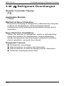
3.33E6 Compressor Overcurrent ............................ 181
3.34E7 Outdoor Unit Fan Motor Abnormality .......... 184
3.35E9 Electronic Expansion Valve Abnormality .... 196
3.36E9 Electronic Expansion Valve Coil
Abnormality ...................................................... 200
3.37F3 Discharge Pipe Temperature
Abnormality ...................................................... 210
3.38F3 Discharge Pipe Temperature Control ......... 218
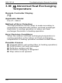
3.39F6 Abnormal Heat Exchanging
Temperature .................................................... 220
3.40F6 Refrigerant Overcharged ............................ 222
3.41H3 High Pressure Switch Abnormality .............. 224
3.42H3 High Pressure Switch System
Abnormality ...................................................... 229
3.43H4 Low Pressure Sensor System
Abnormality ...................................................... 231
ii
SkyAir Series
Si20-701_B
3.44H7 Outdoor Unit Fan Motor Signal
Abnormality ......................................................235
3.45H9, J3, J5, J6, J7, J8 Thermistor System
Abnormality ......................................................237
3.46H9 Outdoor Air Thermistor System
Abnormality ......................................................239
3.47J1 Pressure Sensor Abnormality .....................241
3.48J2 Current Sensor System Abnormality ...........243
3.49J3 Discharge Pipe Thermistor System
Abnormality ......................................................245
3.50J5 Suction Pipe Thermistor Abnormality ..........248
3.51J6 Heat Exchanger Thermistor System
Abnormality ......................................................250
3.52J7 Liquid Pipe Thermistor Abnormality ............252
3.53J9 Subcooling Heat Exchanger Gas Pipe
Thermistor Abnormality ....................................254
3.54JA High Pressure Sensor Abnormality .............256
3.55JC Suction Pipe Pressure Sensor
Abnormality ......................................................259
3.56L1 Outdoor Unit PCB Abnormality ...................261
3.57L1 Outdoor Inverter PCB Abnormality ..............263
3.58L1 Outdoor Unit PCB Abnormality ...................265
3.59L4 Overcurrent of DC Output
(Instantaneous) ................................................268
3.60L4 Radiation Fin Temperature Rise .................270
3.61L5 Overcurrent of DC Output
(Instantaneous) ................................................278
3.62L5 Momentary Overcurrent of Inverter
Compressor .....................................................281
3.63L5 Output Overcurrent Detection .....................284
3.64L5 Inverter Compressor Abnormality ...............287
3.65L5 Output Overcurrent Detection .....................290
3.66(L8) Electronic Thermal Switch (Time Lag) ......294
3.67L8 Inverter Current Abnormality .......................297
3.68L8 Inverter Compressor Overcurrent ...............300
3.69L8 Electronic Thermal (Time Lag) ....................303
3.70L9 Stall Prevention (Time Lag) .........................309
3.71L9 Inverter Startup Error ..................................311
3.72LC Transmission Error Between Inverter and
Control PCB .....................................................317
iii
Si20-701_B
SkyAir Series
3.73LC Transmission Error
(between Control PCB and Inverter PCB) ....... 323
3.74P1 Inverter Over-Ripple Protection ..................326
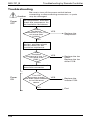
3.75P1 Open Phase or Power Supply Voltage
Imbalance ........................................................ 329
3.76P4 Radiation Fin Thermistor Abnormality ......... 331
3.77P4 Radiation Fin Thermistor or Related
Abnormality ...................................................... 335
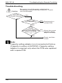
3.78PJ Defective Capacity Setting .......................... 336
3.79PJ Error in Capacity Setting .............................338
3.80PJ Field Setting Error after Replacing Main
PCB or Defective Combination of PCB ............339
3.81PJ Defective Combination of Inverter and
Fan Driver ........................................................ 341
3.82PJ Defective Capacity Setting .......................... 343
3.83U0 Refrigerant Shortage ................................... 347
3.84U0 Low Pressure Drop Due to Refrigerant
Shortage or Electronic Expansion
Valve Failure .................................................... 349
3.85U0 Refrigerant Shortage ................................... 352
3.86U1 Reverse Phase ........................................... 358
3.87U2 Insufficient Voltage ...................................... 361
3.88U2 Power Supply Voltage Abnormality ............. 363
3.89U2 Power Supply Insufficient or Instantaneous
Failure .............................................................. 365
3.90U2 Power Supply Voltage Abnormality ............. 370
3.91U3 Check Operation is not Executed ............... 373
3.92U4 or UF Transmission Error
(Between Indoor Unit and Outdoor Unit) ......... 375
3.93U4 Transmission Error Between Indoor Unit
and Outdoor Unit ............................................. 381
3.94U5 Transmission Error Between Indoor Unit
and Remote Controller .................................... 404
3.95U7 Transmission Error Between Outdoor
Units ................................................................ 412
3.96U8 Transmission Error Between Main Remote
Controller and Sub Remote Controller ............. 415
3.97U9 Transmission Error Between Indoor and
Outdoor Units in the Same System ................. 421
3.98UA Defective Field Setting Switch .................... 424
iv
SkyAir Series
Si20-701_B
3.99UA Improper Combination of Indoor and
Outdoor Units, Indoor Units and
Remote Controller ............................................427
3.100UA Field Setting Switch Abnormality ...............430
3.101UA Field Setting Switch and Transmission
Line Abnormality ..............................................433
3.102UC Centralized Address Setting Error .............437
3.103UC Address Duplication of Centralized
Controller .........................................................438
3.104UE Transmission Error between Centralized
Controller and Indoor Unit ................................439
3.105UF Mis-connection of Field Wiring ..................447
3.106UF System is not Set yet ................................448
3.107UF Transmission Error between Indoor and
Outdoor Unit / Piping and Wiring Mismatch /
Refrigerant Shortage .......................................450
3.108UF Transmission System Abnormality
(between Indoor and Outdoor Units) ...............455
3.109UH System Error, Refrigerant System
Address Undefined ..........................................456
3.110Check ............................................................459
v
Si20-701_B
vi
SkyAir Series
List of Applicable Models
Si20-701_B
1. List of Applicable Models
R-FU Series
Series
Outdoor Units
R71FUV1
R-FUV1
R-FUY1
R-FUVAL
R-FUTAL
Indoor Units
FA71FVEK
R100FUV1
FA100FVEK
R71FUV1
FH71BVE
R100FUV1
FH100BVE
R71FUV1
FHC71KVE
R100FUV1
FHC100KVE
R71FUV1
FV71LVE
R100FUV1
FV100LVE
R71FUY1
FA71FVEK
R100FUY1
FA100FVEK
R71FUY1
FH71BVE
R100FUY1
FH100BVE
R125FUY1
FH125BVE
R71FUY1
FHC71KVE
R100FUY1
FHC100KVE
R125FUY1
FHC125KVE
R140KUY1
FHYC140KVE
R71FUY1
FV71LVE
R100FUY1
FV100LVE
R125FUY1
FV125LVE
R71FUVAL
FA71FVEK
R100FUVAL
FA100FVEK
R71FUVAL
FH71BVE
R100FUVAL
FH100BVE
R71FUVAL
FHC71KVE
R100FUVAL
FHC100KVE
R71FUVAL
FV71LVE
R100FUVAL
FV100LVE
R125FUTAL
FH125BVE
R125FUTAL
FHC125KVE
R125FUTAL
FV125LVE
1
Si20-701_B
List of Applicable Models
R-GA Series
Series
R-GAV
Outdoor Units
Indoor Units
R50GAV1A
FH50BVE
R60GAV1A
FH60BVE
R-G Series
Series
R-GV1
R-GV1A
R-GVAL
R-GV1K
2
Outdoor Units
Indoor Units
R35GV1
FH35BVE
R50GV1
FH50BVE
R60GV1
FH60BVE
R35GV1
FHB35FV1
R50GV1
FHB45FV1
R60GV1
FHB60FV1
R35GV1
FHC35KVE
R50GV1
FHC50KVE
R60GV1
FHC60KVE
R35GV1
FHK35FV1
R50GV1
FHK45FV1
R60GV1
FHK60FV1
R35GV1A
FHC35KVE
R50GV1A
FHC50KVE
R60GV1A
FHC60KVE
R50GVAL
FH50BVE
R60GVAL
FH60BVE
R50GVAL
FHC50KVE
R60GVAL
FHC60KVE
R60GV1K
FHC60KVE
R60GV1K
FH60BVE
R60GV1K
FHB60FV1
R60GV1K
FHK60FV1
List of Applicable Models
Si20-701_B
R-KU Series
Series
Outdoor Units
R71KUV1
R-KUV1
R-KUY1
Indoor Units
FAY71FAVE
R100KUV1
FAY100FAVE
R71KUV1
FHK71FV1
R71KUV1
FHY71BVE
R100KUV1
FHY100BVE
R71KUV1
FHYB71FV1
R100KUV1
FHYB100FV1
R71KUV1
FHYC71KVE
R100KUV1
FHYC100KVE
R71KUV1
FUY71FJV1
R100KUV1
FUY100FJV1
R71KUV1
FVY71LVE
R100KUV1
FVY100LVE
R71KUY1
FAY71FAVE
R100KUY1
FAY100FAVE
R71KUY1
FHK71FV1
R71KUY1
FHY71BVE
R100KUY1
FHY100BVE
R125KUY1
FHY125BVE
R71KUY1
FHYB71FV1
R100KUY1
FHYB100FV1
R125KUY1
FHYB125FV1
R71KUY1
FHYC71KVE
R100KUY1
FHYC100KVE
R125KUY1
FHYC125KVE
R71KUY1
FUY71FJV1
R100KUY1
FUY100FJV1
R125KUY1
FUY125FJV1
R71KUY1
FVY71LVE
R100KUY1
FVY100LVE
R125KUY1
FVY125LVE
3
Si20-701_B
List of Applicable Models
Series
R-KUVAL
R-KUTAL
Outdoor Units
Indoor Units
R71KUVAL
FAY71FAVE
R100KUVAL
FAY100FAVE
R71KUVAL
FHY71BVE
R100KUVAL
FHY100BVE
R71KUVAL
FHYC71KVE
R100KUVAL
FHYC100KVE
R71KUVAL
FVY71LVE
R100KUVAL
FVY100LVE
R125KUTAL
FHY125BVE
R125KUTAL
FHYC125KVE
R140KUTAL
FHYC140KVE
R125KUTAL
FVY125LVE
R-KUTALK
R140KUTALK
FHYC140KVE
R-KUYALK
R140KUYALK
FHYC140KVE
R-KUYAL
R125KUYAL
FHY125BVE
R125KUYAL
FHYC125KVE
R140KUYAL
FHYC140KVE
R125KUYAL
FVY125LVE
R-LU Series
Series
Outdoor Units
R71LUV1
R-LUV1
4
Indoor Units
FAY71FAVE
R100LUV1
FAY100FAVE
R71LUV1
FAY71LVE
R71LUV1
FDYM03FAV1
R100LUV1
FDYM04FAV1
R71LUV1
FHY71BVE
R100LUV1
FHY100BVE
R71LUV1
FHYB71FV1
R100LUV1
FHYB100FV1
R71LUV1
FHYC71KVE
R100LUV1
FHYC100KVE
R71LUV1
FHYK71FJV1
R71LUV1
FUY71FJV1
R100LUV1
FUY100FJV1
R71LUV1
FVY71LAVE
R100LUV1
FVY100LAVE
List of Applicable Models
Series
Outdoor Units
R71LUV1
R-LUV1
(Twin)
R-LUY1
R-LUY1
(Twin)
Si20-701_B
Indoor Units
FHY35BVE × 2
R100LUV1
FHY50BVE × 2
R71LUV1
FHYC35KVE × 2
R100LUV1
FHYC50KVE × 2
R71LUY1
FAY71FAVE
R100LUY1
FAY100FAVE
R71LUY1
FAY71LVE
R71LUY1
FDYM03FAV1
R100LUY1
FDYM04FAV1
R125LUY1
FDYM05FAV1
R140LUY1
FDYM06FAV1
R71LUY1
FHY71BVE
R100LUY1
FHY100BVE
R125LUY1
FHY125BVE
R71LUY1
FHYB71FV1
R100LUY1
FHYB100FV1
R125LUY1
FHYB125FV1
R71LUY1
FHYC71KVE(4)
R100LUY1
FHYC100KVE(4)
R125LUY1
FHYC125KVE(4)
R140LUY1
FHYC140KVE(4)
R71LUY1
FHYK71FJV1
R71LUY1
FUY71FJV1
R100LUY1
FUY100FJV1
R125LUY1
FUY125FJV1
R71LUY1
FVY71LAVE(4)
R100LUY1
FVY100LAVE(4)
R125LUY1
FVY125LAVE(4)
R71LUY1
FHY35BVE × 2
R100LUY1
FHY50BVE × 2
R125LUY1
FHY60BVE × 2
R140LUY1
FHY71BVE × 2
R71LUY1
FHYC35KVE × 2
R100LUY1
FHYC50KVE × 2
R125LUY1
FHYC60KVE × 2
R140LUY1
FHYC71KVE × 2
5
Si20-701_B
Series
R-LUY1
(Triple)
R-LUY2S
(Twin)
R-LUVAL
Outdoor Units
R140LUY1
Indoor Units
FHY50BVE × 3
R140LUY1
FHYC50KVE × 3
R42LUY2S
FHC21KV2S × 2
R71LUVAL
FAY71FAVE
R100LUVAL
FAY100FAVE
R71LUVAL
FAY71LVE
R71LUVAL
FDYM03FAVAL
R100LUVAL
FDYM04FAVAL
R100LUVAL
FHY100BVE
R71LUVAL
FHYC71KVE
R100LUVAL
FHYC100KVE
R71LUVAL
FVY71LAVE
R100LUVAL
FVY100LAVE
R125LUTAL
FDYM05FAVAL
R140LUTAL
FDYM06FAVAL
R125LUTAL
FHY125BVE
R125LUTAL
FVY125LAVE
R-LUTAL
(Twin)
R140LUTAL
FHY71BVE × 2
R140LUTAL
FHYC71KVE × 2
R-LUTAL
(Multi Use)
R140LUTAL
FHY50BVE × 3
R-LUTAL
R-LUYAL
R-LUYAL
(Twin)
R-LUYAL
(Multi Use)
6
List of Applicable Models
R140LUTAL
FHYC50KVE × 3
R125LUYAL
FDYM05FAVAL
R140LUYAL
FDYM06FAVAL
R125LUYAL
FHY125BVE
R125LUYAL
FVY125LAVE
R71LUYAL
FHY35BVE × 2
R100LUYAL
FHY50BVE × 2
R125LUYAL
FHY60BVE × 2
R140LUYAL
FHY71BVE × 2
R71LUYAL
FHYC35KVE × 2
R100LUYAL
FHYC50KVE × 2
R125LUYAL
FHYC60KVE × 2
R140LUYAL
FHYC71KVE × 2
R140LUYAL
FHY50BVE × 3
R140LUYAL
FHYC50KVE × 3
List of Applicable Models
Si20-701_B
R-NU Series
Series
R-NUV1
R-NUY1
Outdoor Units
Indoor Units
R18NUV1(4)(5)
FDBG18NUV1(4)(5)
R21NUV1(4)(5)
FDBG21NUV1(4)(5)
R26NUV1(4)(5)
FDBG26NUV1(4)(5)
R26NUV1(4)(5)
FDMG26NUV1(4)(5)
R30NUV1
FDMG30NUV1
R36NUV1(5)
FDMG36NUV1(5)
R21NUV1(4)(5)
FH21NUV1(4)(5)
R26NUV1(4)(5)
FH26NUV1(4)(5)
R30NUV1
FH30NUV1
R36NUV1(5)
FH36NUV1(5)
R18NUV1(4)(5)
FHC18NUV1(4)(5)
R21NUV1(4)(5)
FHC21NUV1(4)(5)
R26NUV1(4)(5)
FHC26NUV1(4)(5)
R30NUV1
FHC30NUV1
R36NUV1(5)
FHC36NUV1(5)
R26NUY1(4)(5)
FDBG26NUV1(4)(5)
R26NUY1(4)(5)
FDMG26NUV1(4)(5)
R30NUY1
FDMG30NUV1
R36NUY1(4)(5)
FDMG36NUV1(4)(5)
R42NUY1(4)(5)
FDMG42NUV1(4)(5)
R48NUY1(4)(5)
FDMG48NUV1(4)(5)
R51NUY1(4)(5)
FDMG51NUV1(4)(5)
R56NUY1(4)(5)
FDMG56NUV1(4)(5)
R26NUY1(4)(5)
FH26NUV1(4)(5)
R30NUY1
FH30NUV1
R36NUY1(4)(5)
FH36NUV1(4)(5)
R42NUY1(4)(5)
FH42NUV1(4)(5)
R48NUY1(4)(5)
FH48NUV1(4)(5)
R26NUY1(4)(5)
FHC26NUV1(4)(5)
R30NUY1
FHC30NUV1
R36NUY1(4)(5)
FHC36NUV1(4)(5)
R42NUY1(4)(5)
FHC42NUV1(4)(5)
R48NUY1(4)(5)
FHC48NUV1(4)(5)
7
Si20-701_B
Series
List of Applicable Models
Outdoor Units
R13NUV2S
R-NUV2S
8
Indoor Units
FDBT13NUV2S
R13NUV2S
FDBT13PUV2S
R18NUV2S
FDBT18NUV2S
R18NUV2S
FDBT18PUV2S
R24NUV2S
FDBT24NUV2S
R24NUV2S
FDBT24PUV2S
R30NUV2S
FDBT30NUV2S
R30NUV2S
FDBT33NUV2S
R36NUV2S
FDBT36NUV2S
R30NUV2S
FDMG30NUV2S
R36NUV2S
FDMG36NUV2S
R13NUV2S1
FH13NUV2S
R18NUV2S1
FH18NUV2S
R24NUV2S
FH24NUV2S
R30NUV2S
FH30NUV2S
R36NUV2S
FH36NUV2S
R18NUV2S
FHC18NUV2S
R24NUV2S
FHC24NUV2S
R30NUV2S
FHC30NUV2S
R36NUV2S
FHC36NUV2S
List of Applicable Models
Series
R-NUY2S
Outdoor Units
Si20-701_B
Indoor Units
R30NUY2S
FDBT30NUV2S
R30NUY2S
FDBT33NUV2S
R36NUY2S
FDBT36NUV2S
R42NUY2S
FDBT42NUV2S
R48NUY2S
FDBT48NUV2S
R48NUY2S
FDBT48PUV2S
R30NUY2S
FDMG30NUV2S
R36NUY2S
FDMG36NUV2S
R42NUY2S
FDMG42NUV2S
R48NUY2S
FDMG48NUV2S
R51NUY2S
FDMG51NUV2S
R56NUY2S
FDMG56NUV2S
R48NUY2S
FDMG48NVV2S
R51NUY2S
FDMG51NVV2S
R56NUY2S
FDMG56NVV2S
R48NUY2S
FDMG48PUV2S
R51NUY2S
FDMG51PUV2S
R30NUY2S
FH30NUV2S
R36NUY2S
FH36NUV2S
R42NUY2S
FH42NUV2S
R48NUY2S
FH48NUV2S
R30NUY2S
FHC30NUV2S
R36NUY2S
FHC36NUV2S
R42NUY2S
FHC42NUV2S
R48NUY2S
FHC48NUV2S
9
Si20-701_B
List of Applicable Models
R-PU Series
Series
R-PUV2S
R-PUY2S
10
Outdoor Units
Indoor Units
R30PUV2S
FDBT30PUV2S
R33PUV2S
FDBT33PUV2S
R36PUV2S
FDBT36PUV2S
R30PUV2S
FDMG30PUV2S
R36PUV2S
FDMG36PUV2S
R30PUV2S
FDMG30NVV2S
R36PUV2S
FDMG36NVV2S
R30PUV2S
FH30PUV2S
R36PUV2S
FH36PUV2S
R30PUV2S
FHC30PUV2S
R36PUV2S
FHC36PUV2S
R30PUY2S
FH30PUV2S
R36PUY2S
FH36PUV2S
R42PUY2S
FH42PUV2S
R30PUY2S
FHC30PUV2S
R36PUY2S
FHC36PUV2S
R42PUY2S
FHC42PUV2S
R30PUY2S
FDBT30PUV2S
R33PUY2S
FDBT33PUV2S
R36PUY2S
FDBT36PUV2S
R42PUY2S
FDBT42PUV2S
R30PUY2S
FDMG30NVV2S
R36PUY2S
FDMG36NVV2S
R42PUY2S
FDMG42NVV2S
R30PUY2S
FDMG30PUV2S
R36PUY2S
FDMG36PUV2S
R42PUY2S
FDMG42PUV2S
R56NUY2S
FDMG56PUV2S
List of Applicable Models
Si20-701_B
RR-M Series
Series
Outdoor Units
RR71MV1
RR-MV1
RR-MY1
Indoor Units
FAQ71BVV1B
RR71MV1
FBQ71DV1
RR71MV1
FCQ71KVEA
RR71MV1
FHQ71BVV1B
RR71MY1
FAQ71BVV1B
RR100MY1
FAQ100BVV1B
RR71MY1
FBQ71DV1
RR100MY1
FBQ100DV1
RR125MY1
FBQ125DV1
RR140MY1
FBQ140DV1
RR71MY1
FCQ71KVEA
RR100MY1
FCQ100KVEA
RR125MY1
FCQ125KVEA
RR140MY1
FCQ140KVEA
RR71MY1
FHQ71BVV1B
RR100MY1
FHQ100BVV1B
RR125MY1
FHQ125BVV1B
RY-FU Series
Series
RY-FUVAL
RY-FUTAL
Outdoor Units
Indoor Units
RY71FUVAL
FAY71FVE
RY100FUVAL
FAY100FVE
RY71FUVAL
FHY71BVE
RY100FUVAL
FHY100BVE
RY71FUVAL
FHYB71FVAL
RY100FUVAL
FHYB100FVAL
RY71FUVAL
FHYC71KVE
RY100FUVAL
FHYC100KVE
RY71FUVAL
FVY71LVE
RY100FUVAL
FVY100LVE
RY125FUTAL
FHY125BVE
RY125FUTAL
FHYB125FVAL
RY125FUTAL
FHYC125KVE
RY125FUTAL
FVY125LVE
11
Si20-701_B
List of Applicable Models
RY-FV Series
Series
RY-FV1A
Outdoor Units
Indoor Units
RY35FV1A
FHY35BVE
RY35FV1A
FHYB35FV1
RY35FV1A
FHYC35KVE
RY35FV1A
FHYK35FJV1
RY-G Series
Series
RY-GVAL
RY-GV1A
Outdoor Units
Indoor Units
RY50GVAL
FHY50BVE
RY60GVAL
FHY60BVE
RY50GVAL
FHYC50KVE
RY60GVAL
FHYC60KVE
RY50GV1A
FHYB45FV1
RY60GV1A
FHYB60FV1
RY50GV1A
FHYC50KVE
RY60GV1A
FHYC60KVE
RY50GV1A
FHYK45FJV1
RY60GV1A
FHYK60FJV1
RY-GAV Series
Series
RY-GAV
12
Outdoor Units
Indoor Units
RY50GAV1A
FHY50BVE
RY60GAV1A
FHY60BVE
List of Applicable Models
Si20-701_B
RY-KU Series
Series
Outdoor Units
RY71KUV1
RY-KUV1
RY-KUY1
RY-KUTAL
Indoor Units
FAY71FAVE
RY100KUV1
FAY100FAVE
RY71KUV1
FHY71BVE
RY100KUV1
FHY100BVE
RY71KUV1
FHYB71FV1
RY100KUV1
FHYB100FV1
RY71KUV1
FHYC71KVE
RY100KUV1
FHYC100KVE
RY71KUV1
FHYK71FJV1
RY71KUY1
FHYK71FJV1
RY71KUV1
FUY71FJV1
RY100KUV1
FUY100FJV1
RY71KUV1
FVY71LVE
RY100KUV1
FVY100LVE
RY71KUY1
FAY71FAVE
RY100KUY1
FAY100FAVE
RY71KUY1
FHY71BVE
RY100KUY1
FHY100BVE
RY125KUY1
FHY125BVE
RY71KUY1
FHYB71FV1
RY100KUY1
FHYB100FV1
RY125KUY1
FHYB125FV1
RY71KUY1
FHYC71KVE
RY100KUY1
FHYC100KVE
RY125KUY1
FHYC125KVE
RY140KUY1
FHYC140KVE
RY71KUY1
FUY71FJV1
RY100KUY1
FUY100FJV1
RY125KUY1
FUY125FJV1
RY71KUY1
FVY71LVE
RY100KUY1
FVY100LVE
RY125KUY1
FVY125LVE
RY140KUTAL
FHYC140KVE
RY-KUTALK
RY140KUTALK
FHYC140KVE
RY-KUYAL
RY140KUYAL
FHYC140KVE
RY140KUYALK
FHYC140KVE
RY-KUYALK
13
Si20-701_B
List of Applicable Models
RY-LU Series
Series
RY-LUV1
RY-LUV1
(Twin)
14
Outdoor Units
Indoor Units
RY71LUV1
FAY71FAVE
RY100LUV1
FAY100FAVE
RY71LUV1
FAY71LVE
RY71LUV1
FDYB71KAVE
RY71LUV1
FDYM03FAV1
RY100LUV1
FDYM04FAV1
RY71LUV1
FHY71BVE
RY100LUV1
FHY100BVE
RY71LUV1
FHYB71FV1
RY100LUV1
FHYB100FV1
RY71LUV1
FHYC71KVE
RY100LUV1
FHYC100KVE
RY71LUV1
FHYK71FJV1
RY71LUV1
FUY71FJV1
RY100LUV1
FUY100FJV1
RY71LUV1
FVY71LAVE
RY100LUV1
FVY100LAVE
RY71LUV1
FHY35BVE × 2
RY100LUV1
FHY50BVE × 2
RY71LUV1
FHYC35KVE × 2
RY100LUV1
FHYC50KVE × 2
List of Applicable Models
Series
RY-LUY1
Outdoor Units
Si20-701_B
Indoor Units
RY71LUY1
FAY71FAVE
RY100LUY1
FAY100FAVE
RY71LUY1
FAY71LVE
RY140LUY1
FDY06KAY1
RY71LUY1
FDY71KFV1
RY100LUY1
FDY100KFV1
RY125LUY1
FDY125KFV1
RY160LUY1
FDY160KFV1
RY71LUY1
FDYB71KAVE
RY71LUY1
FDYM03FAV1
RY100LUY1
FDYM04FAV1
RY125LUY1
FDYM05FAV1
RY140LUY1
FDYM06FAV1
RY71LUY1
FHY71BVE
RY100LUY1
FHY100BVE
RY125LUY1
FHY125BVE
RY71LUY1
FHYB71FV1
RY100LUY1
FHYB100FV1
RY125LUY1
FHYB125FV1
RY71LUY1
FHYC71KVE
RY100LUY1
FHYC100KVE
RY125LUY1
FHYC125KVE
RY140LUY1
FHYC140KVE
RY71LUY1
FHYK71FJV1
RY71LUY1
FUY71FJV1
RY100LUY1
FUY100FJV1
RY125LUY1
FUY125FJV1
RY71LUY1
FVY71LAVE
RY100LUY1
FVY100LAVE
RY125LUY1
FVY125LAVE
15
Si20-701_B
List of Applicable Models
Series
RY-LUY1
RY-LUY1
RY-LUTAL
RY-LUVAL
Outdoor Units
Indoor Units
RY71LUY1
FHY35BVE × 2
RY100LUY1
FHY50BVE × 2
RY125LUY1
FHY60BVE × 2
RY140LUY1
FHY71BVE × 2
RY71LUY1
FHYC35KVE × 2
RY100LUY1
FHYC50KVE × 2
RY125LUY1
FHYC60KVE × 2
RY140LUY1
FHYC71KVE × 2
RY140LUY1
FHY50BVE × 3
RY140LUY1
FHYC50KVE × 3
RY140LUTAL
FDYM06FAVAL
RY140LUTAL
FHYC140KVE
RY140LUTAL
FHY50KVE × 3
RY140LUTAL
FHY71KVE × 2
RY140LUTAL
FHYC50KVE × 3
RY140LUTAL
FHYC71KVE × 2
RY140LUVAL
FDYM06FAVAL
RY140LUVAL
FHYC140KVE
RY-LUYAL
(Twin)
RY140LUYAL
FHY71KVE × 2
RY140LUYAL
FHYC71KVE × 2
RY-LUYAL
(Triple)
RY140LUYAL
FHY50KVE × 3
RY140LUYAL
FHYC50KVE × 3
RZ-L Series
Series
Outdoor Units
RZ71LV1
RZ-LV1
16
Indoor Units
FAY71FAVE
RZ71LV1
FHYB71FV1
RZ71LV1
FHYC71KVE
List of Applicable Models
Si20-701_B
RZQ-B Series
Series
RZQ-B7V3B
RZQ-B8W1B
RZQ-B8W1B
(Twin)
Outdoor Units
RZQS100B7V3B
Indoor Units
FCQ35C7VEB × 3
RZQ100B8W1B
FAQ100BUV1B
RZQ100B8W1B
FBQ100B7V3B
RZQ125B8W1B
FBQ125B7V3B
RZQ100B8W1B
FCQ100C7VEB
RZQ125B8W1B
FCQ125C7VEB
RZQ100B8W1B
FCQH100C7VEB
RZQ125B8W1B
FCQH125C7VEB
RZQ140B8W1B
FCQH140C7VEB
RZQ125B8W1B
FDQ125B7V3B
RZQ100B8W1B
FHQ100BUV1B
RZQ125B8W1B
FHQ125BUV1B
RZQ100B8W1B
FUQ100BUV1B
RZQ125B8W1B
FUQ125BUV1B
RZQ140B8W1B
FAQ71BUV1B × 2
RZQ100B8W1B
FBQ50B7V1 × 2
RZQ125B8W1B
FBQ60B7V1 × 2
RZQ140B8W1B
FBQ71B7V3B × 2
RZQ100B8W1B
FCQ50C7VEB × 2
RZQ125B8W1B
FCQ60C7VEB × 2
RZQ140B8W1B
FCQ71C7VEB × 2
RZQ140B8W1B
FCQH71C7VEB × 2
RZQ100B8W1B
FFQ50BV1B × 2
RZQ125B8W1B
FFQ60BV1B × 2
RZQ100B8W1B
FHQ50BUV1B × 2
RZQ125B8W1B
FHQ60BUV1B × 2
RZQ140B8W1B
FHQ71BUV1B × 2
RZQ140B8W1B
FUQ71BUV1B × 2
17
Si20-701_B
Series
RZQ-B8W1B
(Triple)
RZQ-B8W1B
(Double-twin)
RZQ-B9V3B
RZQ-B9V3B
(Twin)
18
List of Applicable Models
Outdoor Units
Indoor Units
RZQ100B8W1B
FBQ35B7V1 × 3
RZQ125B8W1B
FBQ50B7V1 × 3
RZQ140B8W1B
FBQ50B7V1 × 3
RZQ100B8W1B
FCQ35C7VEB × 3
RZQ125B8W1B
FCQ50C7VEB × 3
RZQ140B8W1B
FCQ50C7VEB × 3
RZQ100B8W1B
FFQ35BV1B × 3
RZQ125B8W1B
FFQ50BV1B × 3
RZQ140B8W1B
FFQ50BV1B × 3
RZQ100B8W1B
FHQ35BUV1B × 3
RZQ125B8W1B
FHQ50BUV1B × 3
RZQ140B8W1B
FHQ50BUV1B × 3
RZQ125B8W1B
FBQ35B7V1 × 4
RZQ140B8W1B
FBQ35B7V1 × 4
RZQ125B8W1B
FCQ35C7VEB × 4
RZQ140B8W1B
FCQ35C7VEB × 4
RZQ125B8W1B
FFQ35BV1B × 4
RZQ140B8W1B
FFQ35BV1B × 4
RZQ125B8W1B
FHQ35BUV1B × 4
RZQ140B8W1B
FHQ35BUV1B × 4
RZQ71B9V3B
FAQ71BUV1B
RZQ71B9V3B
FBQ71B7V3B
RZQ71B9V3B
FCQ71C7VEB
RZQ71B9V3B
FCQH71C7VEB
RZQ71B9V3B
FHQ71BUV1B
RZQ71B9V3B
FUQ71BUV1B
RZQ71B9V3B
FBQ35B7V1 × 2
RZQ71B9V3B
FCQ35C7VEB × 2
RZQ71B9V3B
FFQ35BV1B × 2
RZQ71B9V3B
FHQ35BUV1B × 2
List of Applicable Models
Si20-701_B
RZQ-C Series
Series
RZQ-C7V1B
Outdoor Units
Indoor Units
RZQ71C7V1B
FAQ71BUV1B
RZQ100C7V1B
FAQ100BUV1B
RZQ71C7V1B
FBQ71B7V3B
RZQ100C7V1B
FBQ100B7V3B
RZQ125C7V1B
FBQ125B7V3B
RZQ100C7V1B
FCQ100C7VEB
RZQ125C7V1B
FCQ125C7VEB
RZQ140C7V1B
FCQ140C7VEB
RZQ71C7V1B
FCQ71C7V3B
RZQ100C7V1B
FCQ100C7V3B
RZQ125C7V1B
FCQ125C7V3B
RZQ140C7V1B
FCQ140C7V3B
RZQ100C7V1B
FCQH100C7VEB
RZQ125C7V1B
FCQH125C7VEB
RZQ140C7V1B
FCQH140C7VEB
RZQ71C7V1B
FCQH71C7V3B
RZQ100C7V1B
FCQH100C7V3B
RZQ125C7V1B
FCQH125C7V3B
RZQ140C7V1B
FCQH140C7V3B
RZQ125C7V1B
FDQ125B7V3B
RZQ71C7V1B
FHQ71BUV1B
RZQ100C7V1B
FHQ100BUV1B
RZQ125C7V1B
FHQ125BUV1B
RZQ71C7V1B
FUQ71BUV1B
RZQ100C7V1B
FUQ100BUV1B
RZQ125C7V1B
FUQ125BUV1B
19
Si20-701_B
Series
RZQ-C7V1B
(Twin)
RZQ-C7V1B
(Triple)
20
List of Applicable Models
Outdoor Units
Indoor Units
RZQ140C7V1B
FAQ71BUV1B × 2
RZQ71C7V1B
FBQ35B7V1 × 2
RZQ100C7V1B
FBQ50B7V1 × 2
RZQ125C7V1B
FBQ60B7V1 × 2
RZQ140C7V1B
FBQ71B7V3B × 2
RZQ100C7V1B
FCQ50C7VEB × 2
RZQ125C7V1B
FCQ60C7VEB × 2
RZQ140C7V1B
FCQ71C7VEB × 2
RZQ71C7V1B
FCQ35C7V3B × 2
RZQ100C7V1B
FCQ50C7V3B × 2
RZQ125C7V1B
FCQ60C7V3B × 2
RZQ140C7V1B
FCQ71C7V3B × 2
RZQ140C7V1B
FCQH71C7VEB × 2
RZQ71C7V1B
FFQ35BV1B × 2
RZQ100C7V1B
FFQ50BV1B × 2
RZQ125C7V1B
FFQ60BV1B × 2
RZQ71C7V1B
FHQ35BUV1B × 2
RZQ100C7V1B
FHQ50BUV1B × 2
RZQ125C7V1B
FHQ60BUV1B × 2
RZQ140C7V1B
FHQ71BUV1B × 2
RZQ140C7V1B
FUQ71BUV1B × 2
RZQ100C7V1B
FBQ35B7V1 × 3
RZQ125C7V1B
FBQ50B7V1 × 3
RZQ140C7V1B
FBQ50B7V1 × 3
RZQ100C7V1B
FCQ35C7VEB × 3
RZQ125C7V1B
FCQ50C7VEB × 3
RZQ140C7V1B
FCQ50C7VEB × 3
RZQ100C7V1B
FCQ35C7V3B × 3
RZQ125C7V1B
FCQ50C7V3B × 3
RZQ140C7V1B
FCQ50V7V3B × 3
RZQ100C7V1B
FFQ35BV1B × 3
RZQ125C7V1B
FFQ50BV1B × 3
RZQ140C7V1B
FFQ50BV1B × 3
RZQ100C7V1B
FHQ35BUV1B × 3
RZQ125C7V1B
FHQ50BUV1B × 3
RZQ140C7V1B
FHQ50BUV1B × 3
List of Applicable Models
Series
Outdoor Units
RZQ125C7V1B
RZQ-C7V1B
(Double-twin)
RZQ-C7Y1B
RZQ-C7Y1B
(Twin)
RZQ-C7Y1B
(Triple)
Si20-701_B
Indoor Units
FBQ35B7V1 × 4
RZQ140C7V1B
FBQ35B7V1 × 4
RZQ125C7V1B
FCQ35C7VEB × 4
RZQ140C7V1B
FCQ35C7VEB × 4
RZQ125C7V1B
FCQ35C7V3B × 4
RZQ140C7V1B
FCQ35C7V3B × 4
RZQ125C7V1B
FFQ35BV1B × 4
RZQ140C7V1B
FFQ35BV1B × 4
RZQ125C7V1B
FHQ35BUV1B × 4
RZQ140C7V1B
FHQ35BUV1B × 4
RZQ200C7Y1B
FDQ200B7V3B
RZQ250C7Y1B
FDQ250B7V3B
RZQ200C7Y1B
FAQ100BUV1B × 2
RZQ200C7Y1B
FBQ 100B7V3B × 2
RZQ250C7Y1B
FBQ 125B7V3B × 2
RZQ200C7Y1B
FCQ100C7VEB × 2
RZQ250C7Y1B
FCQ125C7VEB × 2
RZQ250C7Y1B
FDQ125B7V3B × 2
RZQ200C7Y1B
FHQ100BUV1B × 2
RZQ250C7Y1B
FHQ125BUV1B × 2
RZQ200C7Y1B
FUQ100BUV1B × 2
RZQ250C7Y1B
FUQ125BUV1B × 2
RZQ200C7Y1B
FAQ71BUV1B × 3
RZQ200C7Y1B
FBQ60B7V1 × 3
RZQ200C7Y1B
FBQ71B7V3B × 3
RZQ200C7Y1B
FCQ60C7VEB × 3
RZQ200C7Y1B
FCQ71C7VEB × 3
RZQ200C7Y1B
FFQ60BV1B × 3
RZQ200C7Y1B
FHQ60BUV1B × 3
RZQ200C7Y1B
FHQ71BUV1B × 3
RZQ200C7Y1B
FUQ71BUV1B × 3
21
Si20-701_B
Series
List of Applicable Models
Outdoor Units
RZQ200C7Y1B
RZQ-C7Y1B
(Double-twin)
Indoor Units
FBQ50B7V1 × 4
RZQ250C7Y1B
FBQ60B7V1 × 4
RZQ200C7Y1B
FCQ50C7VEB × 4
RZQ250C7Y1B
FCQ60C7VEB × 4
RZQ200C7Y1B
FFQ50BV1B × 4
RZQ250C7Y1B
FFQ60BV1B × 4
RZQ200C7Y1B
FHQ50BUV1B × 4
RZQ250C7Y1B
FHQ60BUV1B × 4
RZQG-L Series
Series
RZQG-LV1B
22
Outdoor Units
Indoor Units
RZQG71LV1B
FCQG71EVEB
RZQG100LV1B
FCQG100EVEB
RZQG125LV1B
FCQG125EVEB
RZQG140LV1B
FCQG140EVEB
RZQG71LV1B
FHQG71CVEB
RZQG100LV1B
FHQG100CVEB
RZQG125LV1B
FHQG125CVEB
RZQG140LV1B
FHQG140CVEB
List of Applicable Models
Si20-701_B
RZQ-H Series
Series
RZQ-HY
Outdoor Units
Indoor Units
RZQ100HY4A
FBQ100DV1
RZQ125HY4A
FBQ125DV1
RZQ160HY4A
FBQ140DV1
RZQ100HY4A
FCQ100KVEA
RZQ125HY4A
FCQ125KVEA
RZQ100HY4A
FHQ100BVV1B
RZQ125HY4A
FHQ125BVV1B
RZQ-K Series
Series
Outdoor Units
RZQ71KAVLT
RZQ-KA
RZQ-KB
RZQ-KC
Indoor Units
FBQ71DVET
RZQ100KAVLT
FBQ100DVET
RZQ125KATLT
FBQ125DVET
RZQ140KATLT
FBQ140DVET
RZQ71KAVLT
FCQ71KVLT
RZQ100KAVLT
FCQ100KVLT
RZQ125KATLT
FCQ125KVLT
RZQ140KATLT
FCQ140KVLT
RZQ71KBV1
FAQ71BVV1B
RZQ100KBV1
FAQ100BVV1B
RZQ71KBV1
FBQ71DV1
RZQ71KBV1
FCQ71KVEA
RZQ100KBV1
FCQ100KVEA
RZQ160HY4A
FCQ140KVEA
RZQ71KBV1
FHQ71BVV1B
RZQ100KBV1
FHQ100BVV1B
RZQ71KCVLT
FBQ71DAVET
RZQ100KCVLT
FBQ100DAVET
RZQ125KCTLT
FBQ125DAVET
RZQ140KCTLT
FBQ140DAVET
RZQ71KCVLT
FCQ71KVLT
RZQ100KCVLT
FCQ100KVLT
RZQ125KCTLT
FCQ125KAVLT
RZQ140KCTLT
FCQ140KAVLT
23
Si20-701_B
List of Applicable Models
RZQS-B Series
Series
RZQS-B7V3B
Outdoor Units
FAQ71BUV1B
RZQS100B7V3B
FAQ100BUV1B
RZQS71B7V3B
FBQ71B7V3B
RZQS100B7V3B
FBQ100B7V3B
RZQS71B7V3B
FCQ71C7VEB
RZQS100B7V3B
FCQ100C7VEB
RZQS71B7V3B
FCQH71C7VEB
RZQS100B7V3B
FCQH100C7VEB
RZQS71B7V3B
FHQ71BUV1B
RZQS100B7V3B
FHQ100BUV1B
RZQS71B7V3B
FUQ71BUV1B
RZQS100B7V3B
FUQ100BUV1B
RZQS71B7V3B
FBQ35B7V1 × 2
RZQS100B7V3B
FBQ50B7V1 × 2
RZQS71B7V3B
FCQ35C7VEB × 2
RZQS-B7V3B RZQS100B7V3B
(Twin)
RZQS71B7V3B
FCQ50C7VEB × 2
FFQ35BV1B × 2
RZQS100B7V3B
FFQ50BV1B × 2
RZQS71B7V3B
FHQ35BUV1B × 2
RZQS100B7V3B
FHQ50BUV1B × 2
RZQS100B7V3B
FFQ35BV1B × 3
RZQS-B7V3B
RZQS100B7V3B
(Triple)
RZQS100B7V3B
24
Indoor Units
RZQS71B7V3B
FBQ35B7V1 × 3
FHQ35BUV1B × 3
List of Applicable Models
Si20-701_B
RZQS-C Series
Series
RZQS-C7V1B
Outdoor Units
Indoor Units
RZQS125C7V1B
FBQ125B7V3B
RZQS125C7V1B
FCQ125C7VEB
RZQS140C7V1B
FCQ140C7VEB
RZQS125C7V1B
FCQH125C7VEB
RZQS140C7V1B
FCQH140C7VEB
RZQS125C7V1B
FDQ125B7V3B
RZQS125C7V1B
FHQ125BUV1B
RZQS125C7V1B
FUQ125BUV1B
RZQS140C7V1B
FAQ71BUV1B × 2
RZQS125C7V1B
FBQ60B7V1 × 2
RZQS140C7V1B
FBQ71B7V3B × 2
RZQS125C7V1B
FCQ60C7VEB × 2
RZQS-C7V1B RZQS140C7V1B
(Twin)
RZQS140C7V1B
FCQ71C7VEB × 2
FCQH71C7VEB × 2
RZQS125C7V1B
FFQ60BV1B × 2
RZQS125C7V1B
FHQ60BUV1B × 2
RZQS140C7V1B
FHQ71BUV1B × 2
RZQS140C7V1B
FUQ71BUV1B × 2
RZQS125C7V1B
FBQ50B7V1 × 3
RZQS140C7V1B
FBQ50B7V1 × 3
RZQS125C7V1B
FCQ50C7VEB × 3
RZQS-C7V1B RZQS140C7V1B
(Triple)
RZQS125C7V1B
FCQ50C7VEB × 3
FFQ50BV1B × 3
RZQS140C7V1B
FFQ50BV1B × 3
RZQS125C7V1B
FHQ50BUV1B × 3
RZQS140C7V1B
FHQ50BUV1B × 3
RZQS125C7V1B
FBQ35B7V1 × 4
RZQS140C7V1B
FBQ35B7V1 × 4
RZQS125C7V1B
FCQ35C7VEB × 4
RZQS-C7V1B RZQS140C7V1B
(Double-twin) RZQS125C7V1B
FCQ35C7VEB × 4
FFQ35BV1B × 4
RZQS140C7V1B
FFQ35BV1B × 4
RZQS125C7V1B
FHQ35BUV1B × 4
RZQS140C7V1B
FHQ35BUV1B × 4
25
Si20-701_B
List of Applicable Models
RZR-HU Series
Series
RZR-HUY1
RZR-HUY2S
Outdoor Units
Indoor Units
RZR100HUY1
FBQ100DV1
RZR125HUY1
FBQ125DV1
RZR140HUY1
FBQ140DV1
RZR100HUY1
FCQ100KVEA
RZR125HUY1
FCQ125KVEA
RZR140HUY1
FCQ140KVEA
RZR100HUY1
FHQ100BV1B
RZR125HUY1
FHQ125BV1B
RZR100HUY1
FHQ100BVV1B
RZR125HUY1
FHQ125BVV1B
RZR30HUY2S
FBQ30DV2S
RZR36HUY2S
FBQ36DV2S
RZR42HUY2S
FBQ42DV2S
RZR48HUY2S
FBQ48DV2S
RZR30HUY2S
FCQ30KV2S
RZR36HUY2S
FCQ36KV2S
RZR42HUY2S
FCQ42KV2S
RZR48HUY2S
FCQ48KV2S
RZR-KU Series
Series
RZR-KUV1
26
Outdoor Units
Indoor Units
RZR71KUV1
FBQ71DV1
RZR100KUV1
FBQ100DV1
RZR125KUV1
FBQ125DV1
RZR140KUV1
FBQ140DV1
RZR71KUV1
FCQ71KVEA
RZR100KUV1
FCQ100KVEA
RZR125KUV1
FCQ125KVEA
RZR140KUV1
FCQ140KVEA
RZR71KUV1
FHQ71BV1B
RZR100KUV1
FHQ100BV1B
RZR125KUV1
FHQ125BV1B
RZR71KUV1
FHQ71BVV1B
RZR100KUV1
FHQ100BVV1B
RZR125KUV1
FHQ125BVV1B
List of Applicable Models
Series
RZR-KUV2S
Outdoor Units
Si20-701_B
Indoor Units
RZR30KUV2S
FBQ30DV2S
RZR36KUV2S
FBQ36DV2S
RZR42KUV2S
FBQ42DV2S
RZR48KUV2S
FBQ48DV2S
RZR30KUV2S
FCQ30KV2S
RZR36KUV2S
FCQ36KV2S
RZR42KUV2S
FCQ42KV2S
RZR48KUV2S
FCQ48KV2S
RZY-L Series
Series
Outdoor Units
RZY71LV1
RZY-LV1
RZY-LVAL
RZY-LTAL
Indoor Units
FAY71FAVE
RZY71LV1
FHYB71FV1
RZY71LV1
FHYC71KVE
RZY71LVAL
FAY71FAVE
RZY71LVAL
FHYB71FVAL
RZY71LVAL
FHYC71KVE
RZY100LTAL
FAY100FAVE
RZY100LTAL
FHYB100FVAL
RZY125LTAL
FHYB125FVAL
RZY100LTAL
FHYC100KVE
RZY125LTAL
FHYC125KVE
RZY100LTAL
FVY100LVE
RZY125LTAL
FVY125LVE
27
Si20-701_B
List of Applicable Models
CMSQ Series
Series
Outdoor Units
Indoor Units
FMCQ50A7VEB
FMCQ60A7VEB
FMCQ71A7VEB
FMCQ100A7VEB
FMCQ125A7VEB
FMDQ50A7V3B
CMSQ-A7W1B CMSQ200A7W1B
(Multi)
CMSQ250A7W1B
FMDQ60A7V3B
FMDQ71A7V3B
FMDQ100A7V3B
FMDQ125A7V3B
FMDQ50B7VEB
FMDQ60B7VEB
FMDQ71B7VEB
FMDQ100B7VEB
FMDQ125B7VEB
28
Symptom-based Troubleshooting
Si20-701_B
2. Symptom-based
Troubleshooting
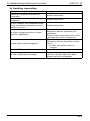
2.1
Overview
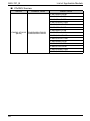
Symptom
Details of Measures
1
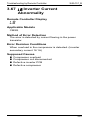
Equipment does not operate.
Refer to P.31
2
Indoor unit fan operates, but
compressor does not operate.
Refer to P.33
3
Cooling/heating operation starts
but stops immediately.
Refer to P.36
4
After unit shuts down, it cannot
be restarted for a while.
Refer to P.38
5
Equipment operates but does
not provide cooling.
Refer to P.41
6
Equipment operates but does
not provide heating.
Refer to P.44
7
Equipment discharges white
mist.
Refer to P.47
8
Equipment produces loud noise
or vibration.
Refer to P.49
9
Equipment discharges dust.
Refer to P.52
10
Remote controller LCD displays
“88”.
Refer to P.53
11
Equipment emits odor.
Room smell and cigarette odors
accumulated inside the indoor
unit are discharged with air.
Inside of the indoor unit must be
cleaned.
12
Flap operates when power is
turned ON.
It is normal.
The flap initializes for accurate
positioning.
13
Change of operation mode
causes flap to move.
It is normal.
There is a control function that
moves the flap when operation
mode is changed.
14
Fan operates in “M” tap during
heating even if remote controller
is set to “L” tap.
It is normal.
It is caused by the activation of
the overload control (airflow shift
control).
15
Flap automatically moves during
cooling.
It is normal.
It is caused by the activation of
the dew condensation
prevention function or ceiling
soiling prevention function.
29
Si20-701_B
Symptom-based Troubleshooting
Symptom
Details of Measures
16
Indoor unit fan operates in “L”
tap for 1 minute in “program dry”
mode even if compressor is not
operating.
It is normal.
The monitoring function forcibly
operates the fan for 1 minute.
17
Indoor unit fan operates after
heating operation stops.
It is normal.
The fan operates in the “LL” tap
for 60 to 100 seconds to
dissipate the residual heat in the
heater.
18
Drain pump operates when
equipment is not operating.
It is normal.
The drain pump continues to
operate for several minutes after
equipment is turned OFF.
19
Horizontal swing sends air to
different directions in cooling
and heating even if it is set to
the same position.
It is normal.
The airflow direction in cooling/
dry operation is different from
that in heating/fan operation.
20
Flap remains horizontal even if it
is set to swing mode.
It is normal.
The flap does not swing in the
thermostat OFF mode.
21
When operating in remote
control thermostat, the
thermostat turns OFF before
temperature of remote control
reaches the set temperature.
It is normal.
The thermostat may be
controlled with the suction air
temperature (body thermostat),
concurrently with the set
temperature.
30
Symptom-based Troubleshooting
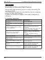
2.2
Si20-701_B
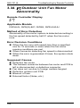
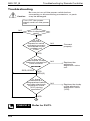
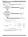
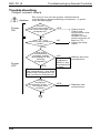
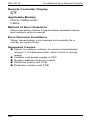
Equipment does not Operate
Applicable Model
All models of SkyAir series
Supposed Causes
Fuse blown or disorder of contact in operation circuit
Defective operation switch or contact point
Defective high pressure switch
Defective magnetic switch for fan motor
Activation or fault of overcurrent relay for fan motor
Defective overcurrent relay for compressor
Defective compressor protection thermostat
Insufficient insulation in electric system
Defective contact point of magnetic switch for
compressor
Defective compressor
Defective remote controller or low batteries (wireless)
Incorrect address setting of wireless remote controller
31
Si20-701_B
Symptom-based Troubleshooting
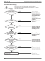
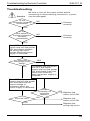
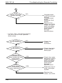
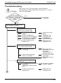
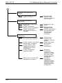
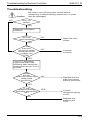
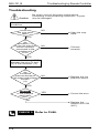
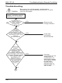
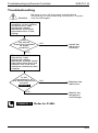
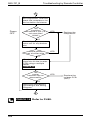
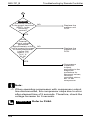
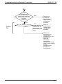
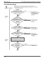
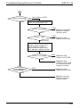
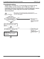
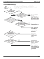
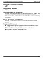
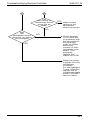
Troubleshooting
Caution
Be sure to turn off the power switch before
connecting or disconnecting connectors, or parts
may be damaged.
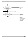
Is the
power switch
OFF or fuse for power
switch blown?
YES
NO
Is there
power failure?
YES
Turn ON the
power switch or
replace the fuse.
If high-harmonics
circuit breaker is
not used on the
inverter
compressor,
replace the circuit
breaker.
Wait until power
returns.
NO
Is the
operation
switch pressed
repeatedly?
YES
NO
Is the
thermostat
changed and reset
again?
YES
NO
Is the
operation
lamp on LCD remote
controller
blinking?
YES
Normal. Start up
operation after 3
minutes (3-min.
standby).
Normal. Start up
operation after 3
minutes (3-min.
standby).
Diagnose based
on error code on
remote controller.
NO
Is the
operation
lamp on indoor unit
signal receiving part
blinking?
YES
Diagnose based
on error code on
remote controller.
NO
Defective electric
component
32
Check the
electric system.
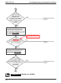
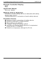
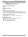
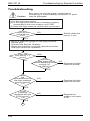
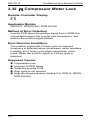
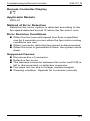
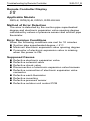
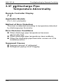
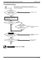
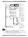
Symptom-based Troubleshooting
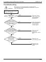
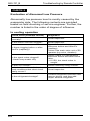
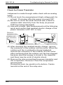
2.3
Si20-701_B
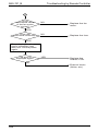
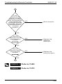
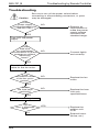
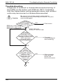
Indoor Unit Fan Operates, but
Compressor does not Operate
Applicable Model
All models of SkyAir series
Supposed Causes
Fuse blown or disorder of contact in operation circuit
Defective thermistor
Defective indoor/outdoor unit PCB
Defective magnetic switch
Defective power transistor
Defective compressor
33
Si20-701_B
Symptom-based Troubleshooting
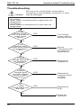
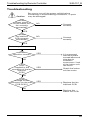
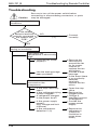
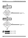
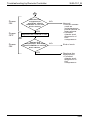
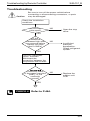
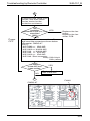
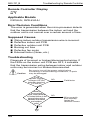
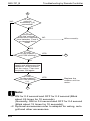
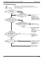
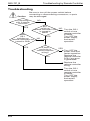
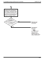
Troubleshooting
Caution
Be sure to turn off the power switch before
connecting or disconnecting connectors, or parts
may be damaged.
· Indoor unit fan runs at setting airflow rate.
· (In cooling)
When suction air temperature is higher than set
temperature
· (In heating)
When suction air temperature is lower than set
temperature
Is the
power switch
OFF or the fuse for
power switch
blown?
YES
Turn ON the
power switch or
replace the fuse.
NO
Is the
heating switch
turned ON at outdoor
air temperature >
32˚C
YES
Normal.
(Thermostat OFF
by outdoor air
temperature)
NO
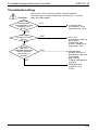
(1)
Is rated
voltage applied at
the compressor
terminals?
YES
Replace the
compressor.
NO
(2)
Is rated
voltage output
from the magnetic
switch or power
transistor?
YES
Replace the
magnetic switch
or power
transistor.
NO
(3)
Is rated
voltage output from
the PCB?
YES
Replace the
PCB.
NO
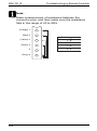
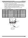
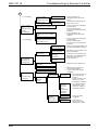
Check the
thermistor.
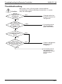
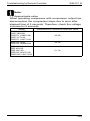
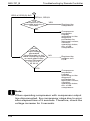
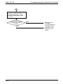
34
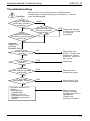
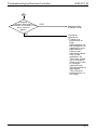
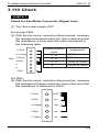
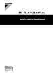
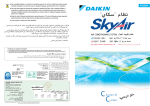
Suction air
thermistor
Input
to
PCB
Output
from
PCB
Indoor unit PCB
Input
to
PCB
Relay
Outdoor unit PCB
e
Output from
relay or microcomputer
Magnetic
switch or
power
transistor
d
Output from
magnetic
switch or SW
circuit of
power
transistor
COMP.
c
Output from
Compressor
Symptom-based Troubleshooting
Si20-701_B
35
Si20-701_B
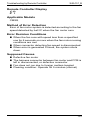
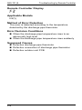
2.4
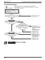
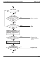
Symptom-based Troubleshooting
Cooling / Heating Operation
Starts but Stops Immediately
Applicable Model
All models of SkyAir series
Supposed Causes
36
Refrigerant overcharge
Air mixed in refrigerant system
Defective pressure switch
Defective magnetic switch for outdoor unit fan motor
Defective aux. relay for outdoor unit fan motor
Soiled heat exchanger of outdoor unit
There is an interfering item in airflow of outdoor unit
Defective outdoor unit fan
Soiled air filter of indoor unit
Soiled heat exchanger of indoor unit
There is some interfering item in airflow of indoor unit
Defective indoor unit fan
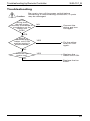
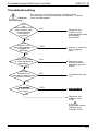
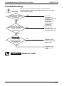
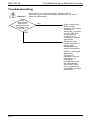
Symptom-based Troubleshooting
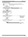
Si20-701_B
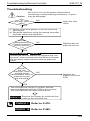
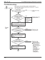
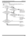
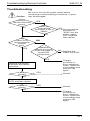
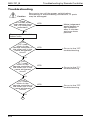
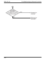
Troubleshooting
Caution
Be sure to turn off the power switch before
connecting or disconnecting connectors, or parts
may be damaged.
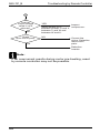
Is the
type of remote
controller wired or
wireless?
Wireless
Is the
operation lamp
of indoor unit receiver
blinking?
wired
Is the
operation lamp of
remote controller
blinking?
YES
NO
YES
Diagnose based
on the error code
on remote
controller
NO
Heating:
Indoor unit
Cooling:
Outdoor unit
Does the fan
rotate?
NO
YES
Is the filter
soiled?
YES
Defective fan
motor. Check the
magnetic switch
and aux. relay for
fan motor.
Cleaning
NO
Is there
any interfering item
in airflow?
YES
Remove the
interfering item.
NO
Is the heat
exchanger soiled?
YES
Cleaning of the
heat exchanger
NO
Possible causes as
follows:
• Refrigerant
overcharge
• Mixing of air in
refrigerant system
• Defective pressure
switch
After vacuum
drying, charge
correct amount of
refrigerant.
Check the
pressure switch.
37
Si20-701_B
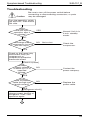
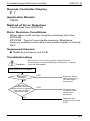
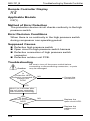
2.5
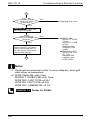
Symptom-based Troubleshooting
After Unit Shuts Down, It
cannot be Restarted for a
While
Applicable Model
All models of SkyAir series
Supposed Causes
Overcurrent relay (for compressor)
Overcurrent relay may act due to the following
reasons
• Lower voltage of power supply
• Excess level of high pressure
• Insufficient size of power cable
• Defective compressor
Compressor protection thermostat
Compressor protection thermostat may act due to the
following reasons
• Internal leakage of four way valve (There is no
difference between suction air temperature and
discharge pipe temperature)
• Insufficient compression of compressor
• Incorrect refrigerant
• Defective electronic expansion valve
• Insufficient circulation of refrigerant
38
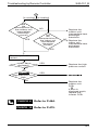
Symptom-based Troubleshooting
Si20-701_B
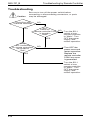
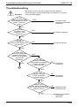
Troubleshooting
Caution
Be sure to turn off the power switch before
connecting or disconnecting connectors, or parts
may be damaged.
Turn the operation switch
ON and OFF, then wait at
ON side.
Does
the unit start
operation after 3
minutes?
YES
Normal. Unit is in
3-min. standby
mode.
NO
Is the
discharge side
of compressor hot after
the unit stops?
NO
Not so hot
Check the
compressor.
YES
Check on the cause why
overcurrent relay (for
compressor) or
compressor protection
thermostat acted.
[Electric system]
Power
supply voltage
is within ±10 % of
specified
voltage.
NO
Contact the
power company.
YES
Is the
size of power
cable through total
length correct?
NO
Replace the
power cable.
YES
[Refrigerant circuit]
After vacuum drying,
charge correct amount of
refrigerant. Then, start
operation again.
A
39
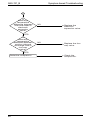
Si20-701_B
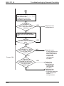
Symptom-based Troubleshooting
A
Is
there any
temperature
difference between
inlet and outlet of
electronic
expansion
valve?
NO
Replace the
electronic
expansion valve.
YES
Is
there any
temperature
difference between
suction side and
discharge side of
four way
valve?
NO
Replace the four
way valve.
YES
Defective compressor
40
Check the
compressor.
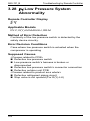
Symptom-based Troubleshooting
2.6
Si20-701_B
Equipment Operates but does
not Provide Cooling
Applicable Model
All models of SkyAir series
Supposed Causes
Wrong selection of model
Refrigerant shortage
Insufficient airflow in the indoor unit
Increase of high pressure
∗ In addition, the following errors may be conceivable
• Insufficient compression of the compressor
• Insufficient circulation of refrigerant
• Defective electronic expansion valve
41
Si20-701_B
Symptom-based Troubleshooting
Troubleshooting
Caution
Be sure to turn off the power switch before
connecting or disconnecting connectors, or parts
may be damaged.
Measure the temperature of suction air and
discharge air.
Temperature difference = Suction air temp.
– Discharge air temp.
Temperature
difference for cooling
should be between
8 and 18˚C.
YES
Does
the heat load
increase after
installation of the
unit?
NO
YES
Normal.
NO
• Wrong selection of
model
• Affection of direct sun
Does
any frost
generate
around inlet port of
indoor unit heat
exchanger or outlet
port of electronic
expansion
valve?
YES
Is the
operation
current less than
specified level?
NO
NO
Does indoor
unit airflow rate
decrease?
NO
A
42
Additional unit
installation
should be
considered.
YES
YES
Refrigerant
shortage possibly
generates
trouble.
After vacuum
drying, charge
correct amount of
refrigerant.
Check the each
section.
• Clogged air
filter
• Soiled heat
exchanger
• Defective fan
motor
(Refer to
troubleshooting
“A6”.)
Symptom-based Troubleshooting
Si20-701_B
A
Is the level of
high pressure higher
than normal level?
NO
YES
Check the each
item.
• Refrigerant
overcharge
• Air mixed in
refrigerant
system
• Soiled heat
exchanger
• Short circuit of
discharge air
• Disturbing item
in airflow
• Defective
outdoor unit fan
motor (Refer to
troubleshooting
“E7”.)
Check the each
item.
• Insufficient
compression of
compressor
• Insufficient
circulation of
refrigerant
• Defective
electronic
expansion valve
43
Si20-701_B
2.7
Symptom-based Troubleshooting
Equipment Operates but does
not Provide Heating
Applicable Model
All models of SkyAir series
Supposed Causes
44
Wrong selection of model
Refrigerant shortage
Insufficient airflow in the indoor unit
Decrease of low pressure
∗ In addition, the following errors may be conceivable
• Insufficient compression of the compressor
• Insufficient circulation of refrigerant
• Defective electronic expansion valve
Symptom-based Troubleshooting
Si20-701_B
Troubleshooting
Caution
Be sure to turn off the power switch before
connecting or disconnecting connectors, or parts
may be damaged.
YES
Is the unit
in defrost mode?
Wait for a while.
Normal
NO
Measure the temperature of suction air and
discharge air.
Temperature difference = Discharge air temp.
– Suction air temp.
Temperature
difference for heating
should be between
14 and 30˚C.
NO
YES
Does the
heat load increase
after installation of the
unit?
YES
Normal
NO
• Wrong selection of
model
• Affection of excessive
fresh air into room
Is the
operation
current less than
specified level?
YES
NO
Does
indoor unit airflow
rate decrease?
NO
A
YES
Additional unit
installation
should be
considered.
Refrigerant
shortage possibly
generates
trouble.
After vacuum
drying, charge
correct amount of
refrigerant.
Check the each
item.
• Clogged air
filter
• Soiled heat
exchanger
• Defective
indoor unit fan
motor
(Refer to
troubleshooting
“A6”)
45
Si20-701_B
Symptom-based Troubleshooting
A
Is the level of
low pressure lower
than normal level?
NO
YES
Check the each
item.
• Refrigerant
overcharge
• Soiled heat
exchanger
• Short circuit of
discharge air
• Disturbing item
in airflow
• Defective
outdoor unit fan
motor (Refer to
troubleshooting
“E7”.)
Check the each
item.
• Insufficient
compression of
compressor
• Insufficient
circulation of
refrigerant
• Defective
electronic
expansion valve
46
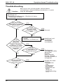
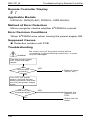
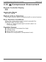
Symptom-based Troubleshooting
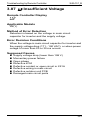
2.8
Si20-701_B
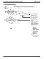
Equipment Discharges White
Mist
Applicable Model
All models of SkyAir series
Supposed Causes
Humid installation site
Installation site is dirty and with dense oil mists
Soiled heat exchanger
Clogged air filter
Defective fan motor
47
Si20-701_B
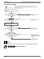
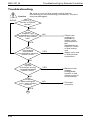
Symptom-based Troubleshooting
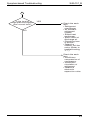
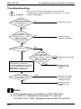
Troubleshooting
Caution
Be sure to turn off the power switch before
connecting or disconnecting connectors, or parts
may be damaged.
Is the room
temperature higher
than set value in
cooling?
NO
YES
Continue
the unit operation.
Is white mist coming
out from the
unit?
YES
Is the
heat exchanger
of indoor unit soiled?
YES
NO
Normal
Remove the
source of humid
condition.
Cleaning of heat
exchanger is
necessary.
NO
Is the
site dusty or
with dense oil mist?
YES
Remove the
source of oil mist
or dust.
NO
Is the
airflow rate too
small?
NO
Did the trouble generate
on switching to heating
mode after complete of
defrosting in heating?
48
YES
Cleaning of air
filter
Check the fan
motor.
(Refer to
troubleshooting
“A6”)
Normal
(Mist is
generated due to
defrosting
operation)
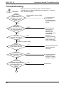
Symptom-based Troubleshooting
2.9
Si20-701_B
Equipment Produces Loud
Noise or Vibration
Applicable Model
All models of SkyAir series
Supposed Causes
Improper installation
Contacts of fan, piping, casing, etc.
Noise of refrigerant flow
Operating noise of drain discharge equipment
Noise of resin components contracting
∗ In addition, the following errors may be conceivable
• Refrigerant overcharge
• Air interfusion
• Flash noise of insufficient refrigerant (hushing
noise)
49
Si20-701_B
Symptom-based Troubleshooting
Troubleshooting
Caution
Be sure to turn off the power switch before
connecting or disconnecting connectors, or parts
may be damaged.
Does
the noise
generate with
vibration of whole
ceilings and
walls?
[Installation work side]
YES
NO
Does
the noise
generate with vibration
of unit mounting
section?
YES
NO
Is the
piping secured?
NO
YES
[Power supply side]
Does
the fan contact
with other parts?
YES
Correction of
installation.
Reinforcement
for ceilings or
walls
Insert shock
absorber in
mounting
section, or
strengthen the
mounting
section.
Insert cushion
materials to the
pipe support
such as saddle.
Disassemble and
remove parts
contact.
NO
Does the
pipe contact with
casing?
YES
NO
Is the
noise flushing
sound from pressure
reducing valve or
capillary
tube?
NO
A
50
YES
Correct piping
manually or
attach a dead
weight to pipe.
Normal.
Symptom-based Troubleshooting
Si20-701_B
A
Continuous
slight noise of
"shoo..." during cooling
or defrosting
YES
NO
Sound
of "shoo..."
generates just
after operation start or
stop, or defrosting
start or stop.
YES
NO
Sound
of "shoo..."
generates during
cooling or after
operation
stop.
YES
Normal.
The sound is
flushing noise of
refrigerant inside
air conditioning
unit.
Normal.
The noise is a
sound generated
at the time of
refrigerant flow
change or stop.
Normal.
Operation sound
of draining
device
NO
Creak
during heating
and after operation
stop
YES
NO
Is this
an impact
noise at the start/end
of defrosting?
NO
• Refrigerant overcharge
• Air mixed in refrigerant
system
• Flushing noise due to
refrigerant shortage.
(Sound of shoo...)
YES
Normal.
Creak generates
by shrinkage of
resin parts due to
temperature
change.
It is normal.
An impact noise can
be reduced by means
of "Defrost Noise
Reduction Setting."
After vacuum
drying, charge
correct amount of
refrigerant.
51
Si20-701_B
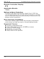
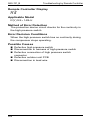
Symptom-based Troubleshooting
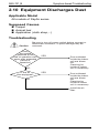
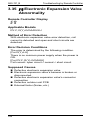
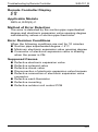
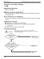
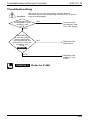
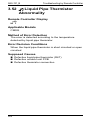
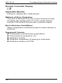
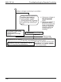
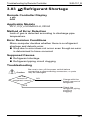
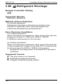
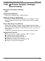
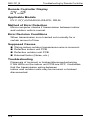
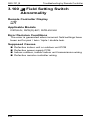
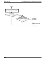
2.10 Equipment Discharges Dust
Applicable Model
All models of SkyAir series
Supposed Causes
Carpet
Animal hair
Application (cloth shop,...)
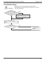
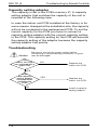
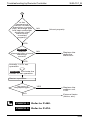
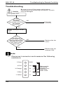
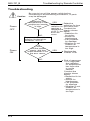
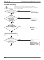
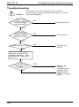
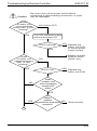
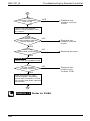
Troubleshooting
Caution
Be sure to turn off power switch before connect or
disconnect connector, or parts damage may be
occurred.
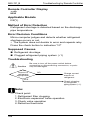
Does
the trouble
generate at the
time of operation start
again after extended
period of
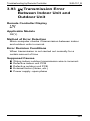
operation?
YES
NO
Is the air
filter equipped?
NO
YES
Dust collected
inside the indoor
unit are blown
out.
Cleaning for
inside of indoor
unit is necessary.
Dust collected
inside the indoor
unit are blown
out.
Cleaning for
inside of indoor
unit is necessary.
Install the air
filter.
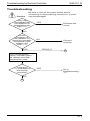
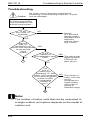
52
Symptom-based Troubleshooting
Si20-701_B
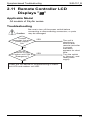
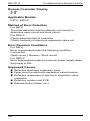
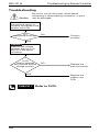
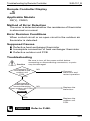
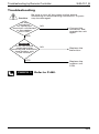
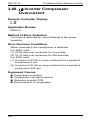
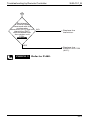
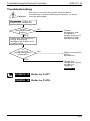
2.11 Remote Controller LCD
Displays "88"
Applicable Model
All models of SkyAir series
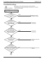
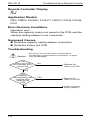
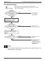
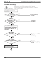
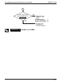
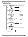
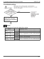
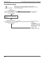
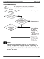
Troubleshooting
Caution
Be sure to turn off the power switch before
connecting or disconnecting connectors, or parts
may be damaged.
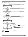
Trouble
generates just after
power supply
ON.
YES
NO
Is the
position of SS1
on indoor unit PCB at
"Emergency"?
YES
The unit is
checking to
confirm that
remote controller
is normal.
Indication
appears for short
time.
Turn the switch
to "Normal", and
reset power
supply.
NO
Check the unit based on troubleshooting of indoor
unit LED and outdoor unit LED.
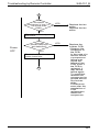
53
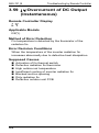
Si20-701_B
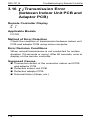
Troubleshooting by Remote Controller
3. Troubleshooting by Remote
Controller
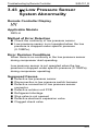
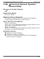
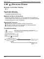
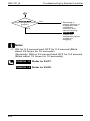
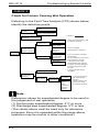
3.1
Procedure of Self-diagnosis
by Remote Controller
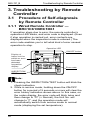
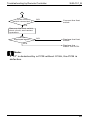
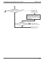
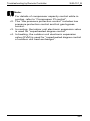
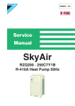
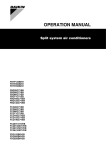
3.1.1 Wired Remote Controller —
BRC1C61/BRC1D61
If operation stops due to error, the remote controller’s
operation LED blinks, and error code is displayed. (Even
if stop operation is carried out, error contents are
displayed when the inspection mode is entered.) The
error code enables you to tell what kind of error caused
operation to stop.
Operation LED
ON/OFF button
Display of
indoor unit for
which an error
has been
detected
Inspection
display
Error code
INSPECTION/
TEST button
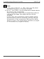
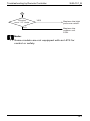
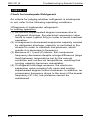
Note:
1. Pressing the INSPECTION/TEST button will blink the
check indication.
2. While in service mode, holding down the ON/OFF
button for a period of 5 seconds or more will clear the
error history indication shown above. In this case, on
the codes display, the error code will blink twice and
then change to “00” (= Normal), the Unit No. will
change to “0”, and the operation mode will
automatically switch from service mode to normal
mode (displaying the set temperature).
54
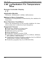
Troubleshooting by Remote Controller
Si20-701_B
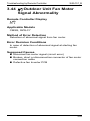
3.1.2 Wired Remote Controller —
BRC1E61
The following will be displayed on the screen when an
error (or a warning) occurs during operation.
Check the error code and take the corrective action
specified for the particular model.
Screen
Operation lamp
(1)Checking an error or warning
Operation
Status
Abnormal
shutdown
Warning
Display
The system
stops
operating.
The operation lamp
(green) starts to
blink. The message
"Error: Press Menu
button" will appear
and blink at the
bottom of the
screen.
The system
continues its
operation.
The operation lamp
(green) remains ON.
The message
"Warning: Press
Menu button" will
appear and blink at
the bottom of the
screen.
55
Si20-701_B
Troubleshooting by Remote Controller
(2)Taking corrective action
· Press the Menu/Enter button to check the error code.
· Take the corrective action specific to the model.
Error code
Applicable
model names
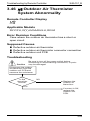
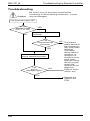
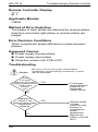
3.1.3 Wireless Remote Controller
If unit stops due to an error, the operation indicating LED
on the signal receiving part of indoor unit blinks.
The error code can be determined by following the
procedure described on next page. (The error code is
displayed when an operation error has occurred. In
normal condition, the error code of the last problem is
displayed.)
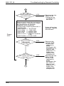
56
Troubleshooting by Remote Controller
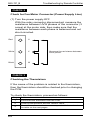
1
Press the INSPECTION/TEST button to select
“inspection”. The equipment enters the inspection
mode. The “Unit” indication is displayed and the
Unit No. display shows blinking “0” indication.
2
Set the Unit No.
Press the UP or DOWN button and change the Unit
No. display until the buzzer (∗1) is generated from
the indoor unit.
∗1 Number of beeps
3 short beeps: Conduct all of the following
operations.
1 short beep: Conduct steps 3 and 4.
Continue the operation in step 4 until
a buzzer remains ON. The
continuous buzzer indicates that the
error code is confirmed.
Continuous beep: No abnormality.
3
Press the MODE selector button.
The left “0” (upper digit) indication of the error code
blinks.
4
Error code upper digit diagnosis
Press the UP or DOWN button and change the
error code upper digit until the error code matching
buzzer (∗2) is generated.
Si20-701_B
The upper digit of the code changes as shown
below when the UP and DOWN buttons are
pressed.
"UP" button "DOWN" button
∗2 Number of beeps
Continuous beep: Both upper and lower digits
matched. (Error code
confirmed)
2 short beeps: Upper digit matched.
1 short beep: Lower digit matched.
5
Press the MODE selector button.
The right “0” (lower digit) indication of the error code
blinks.
6
Error code lower digit diagnosis
Press the UP or DOWN button and change the
error code lower digit until the continuous error code
matching buzzer (∗2) is generated.
The lower digit of the code changes as shown
below when the UP and DOWN buttons are
pressed.
"UP" button
"DOWN" button
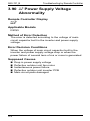
57
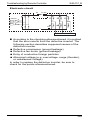
Si20-701_B
Troubleshooting by Remote Controller
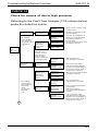
Normal status
Enters inspection mode
from normal status when
the INSPECTION/TEST
button is pressed.
2
1 Press INSPECTION/TEST button.
If no button is
pressed for 1
minute,
equipment
returns to normal
status.
When MODE
selector button is
pressed or no
button is pressed
for 1 minute,
equipment
returns to normal
status.
6
If no button is
pressed for 1
minute,
equipment
4
returns to normal
status.
5 Press MODE selector button.
58
3
Press
MODE
selector
button.
Troubleshooting by Remote Controller
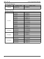
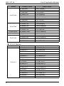
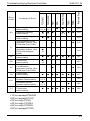
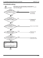
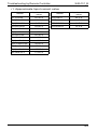
3.2
Si20-701_B
Error Codes and Description
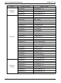
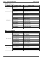
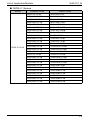
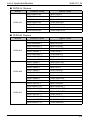
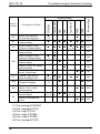
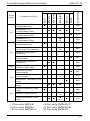
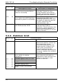
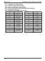
3.2.1 Indoor Unit
FH(Y)C
FH(Y)K
FH(Y)B
FH(Y)
FA(Y)
FV(Y)
FUY, FHC, FH
FDBG, FDBT, FDMG
Reference Page
Model Name
A1
Indoor Unit PCB
Abnormality
h
h
h
h
h
h
h
81
A3
Drain Water Level
System Abnormality
h
h
h
h
h
∗1
h
h
83
A6
Indoor Unit Fan Motor
Abnormality
h
h
∗1
h
86
A7
Swing Flap Motor
Abnormality/Lock
h
h
h
h
h
h
98
AF
Drain System
Abnormality
h
h
h
h
h
∗1
h
h
105
AJ
Capacity Setting
Abnormality
h
h
h
h
h
∗1
h
h
108
C4
Thermistor
Abnormality
h
h
h
h
h
∗1
h
h
121
C9
Thermistor
Abnormality
h
h
h
h
h
∗1
h
h
121
CJ
Remote Controller
Thermistor Abnormality
h
h
∗2
h
h
h
128
Error
Code
Contents of Error
∗1 For only FAY
∗2 For only FHY
59
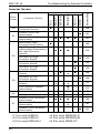
Troubleshooting by Remote Controller
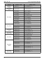
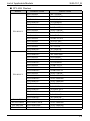
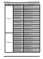
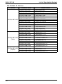
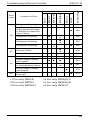
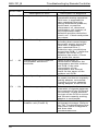
FMDQ
A0
Error of External
Protection Device
h
∗3
A1
Indoor Unit PCB
Abnormality
h
h
h
h
h
h
h
81
A3
Drain Water Level
System Abnormality
h
h
h
h
h
∗2, 6
h
h
83
Indoor Unit Fan Motor
Abnormality
Drain Water Level
System Abnormality
A6
h
∗3
h
∗1
86
h
∗1
88
Indoor Unit Fan Motor
Abnormality
90
h
94
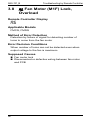
h
Fan Motor (M1F)
Lock, Overload
A7
Swing Flap Motor
Abnormality/Lock
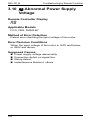
A8
Abnormal Power
Supply Voltage
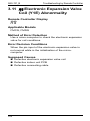
A9
Electronic Expansion
Valve Coil (Y1E)
Abnormality
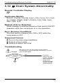
AF
Drain System
Abnormality
Drain Level above
Limit
∗1 For except FHQG
∗2 For except FVG
∗3 For only FCQ
∗4 For only FCQH
∗5 For only FCQG
∗6 For except FVQ
79
h
Indoor Unit Fan Motor
Abnormality
60
FMCQ
FUQ, FFQ, FVQ
FDQ
FBQ
Contents of Error
FHQ(G), FAQ
Error
Code
FCQ(H)(G)
Model Name
Reference Page
Si20-701_B
h
h
h
∗3, 4 ∗1
h
∗3
h
h
h
h
h
96
98
h
h
h
h
∗3, 4 ∗1
h
h
100
h
102
h
∗2, 6
105
h
h
107
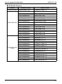
Si20-701_B
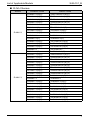
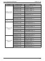
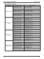
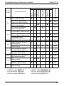
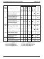
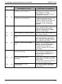
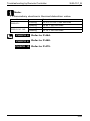
AJ
Capacity Setting
Abnormality
h
∗3
h
∗1
Capacity Setting
Abnormality
h
h
Transmission Error
(between Indoor Unit
PCB and Fan PCB)
C1
h
∗5
C4
Thermistor
Abnormality
h
C5
Thermistor
Abnormality
h
∗4
C6
Defective
Combination
(between Indoor Unit
PCB and Fan PCB)
C9
Thermistor
Abnormality
CJ
h
∗2, 6
h
h
h
∗3, 4
Humidity Sensor
System Abnormality
h
∗3, 5
h
FMDQ
FMCQ
h
110
h
h
112
113
h
115
118
h
h
h
h
h
h
121
121
h
Humidity Sensor
System Abnormality
Remote Controller
Thermistor
Abnormality
h
h
Transmission Error
(between Indoor Unit
PCB and Adaptor
PCB)
CC
FUQ, FFQ, FVQ
h
h
∗3, 4 ∗1
FDQ
Capacity Setting
Abnormality
FBQ
Contents of Error
FHQ(G), FAQ
Error
Code
FCQ(H)(G)
Model Name
Reference Page
Troubleshooting by Remote Controller
h
h
h
h
h
h
123
h
121
125
126
h
h
h
h
h
h
h
128
∗1 For except FHQG
∗2 For except FVG
∗3 For only FCQ
∗4 For only FCQH
∗5 For only FCQG
∗6 For except FVQ
61
Si20-701_B
Troubleshooting by Remote Controller
3.2.2 Outdoor Unit, System
E1
E3
h
h
h
h
135
Defective Outdoor Unit
PCB
h
h
140
High Pressure System
Abnormality
h
h
High Pressure System
Abnormality
Compressor Overcurrent
E9
Electronic Expansion
Valve Abnormality
h
h
h
Discharge Pipe
Temperature Abnormality
h
h
h
h
h
h
h
h
145
h
h
162
h
h
181
210
h
Abnormal Heat
Exchanging Temperature
h
High Pressure Switch
Abnormality
h
h
196
h
Discharge Pipe
Temperature Abnormality
h
224
226
h
Outdoor Air Thermistor
System Abnormality
J2
Current Sensor System
Abnormality
J3
Discharge Pipe
Thermistor System
Abnormality
h
h
h
J6
Heat Exchanger
Thermistor System
Abnormality
h
h
h
h
h
h
212
220
h
High Pressure Switch
Abnormality
H9
62
143
h
E6
H3
132
Actuation of Safety
Device
Low Pressure System
Abnormality
F6
130
Actuation of Safety
Device
E4
F3
R-NU/PU
h
RR-M
R(Y)-KU
h
R(Y)-LU
R(Y)-G/GA
h
Contents of Error
Actuation of Safety
Device
E0
R(Y)-FU
Error
Code
RY-F
Series Name
Reference Page
NON-Inverter Series
h
h
239
h
h
243
h
h
h
245
h
h
h
250
h
Si20-701_B
Defective Capacity
Setting
U0
Refrigerant Shortage
h
h
h
Reverse Phase
h
h
h
U1
U4
Reverse Phase
Transmission Error
(Between Indoor Unit and
Outdoor Unit)
R-NU/PU
h
h
336
h
h
347
h
h
358
359
375
h
Transmission Error
(Between Indoor Unit and
Outdoor Unit)
h
U5
Transmission Error
(Between Indoor Unit and
Remote Controller)
h
U8
Transmission Error
Between
Main Remote Controller
and Sub Remote
Controller
UA
UF
RR-M
PJ
R(Y)-LU
R(Y)-KU
R(Y)-G/GA
Contents of Error
RY-F
Error
Code
R(Y)-FU
Series Name
Reference Page
Troubleshooting by Remote Controller
h
h
h
h
h
378
h
h
h
h
h
404
h
h
h
h
415
Defective Field Setting
Switch
h
h
h
h
424
Transmission Error
(Between Indoor Unit and
Outdoor Unit)
h
h
h
h
Mis-connection of Field
Wiring
h
h
h
h
444
447
63
Si20-701_B
Troubleshooting by Remote Controller
E1
High Pressure
Abnormality (Detected by
the High Pressure
Switch)
h
h
148
h
h
150
h
h
153
Actuation of High
Pressure Switch
h
156
Actuation of High
Pressure Switch
h
159
h
164
h
∗1
h
h
∗4
Actuation of Low
Pressure Sensor
Actuation of Pressure
Sensor
h
h
∗2
Compressor Motor Lock
h
h
Outdoor Unit Fan Motor
Abnormality
171
h
∗6
173
176
h
∗1 For only RZQ-K
∗2 For only RZQ-H
∗3 For only RZQ-KU
h
h
h
168
h
∗5
Compressor Motor Lock
Outdoor Unit Fan Motor
Abnormality
64
141
142
h
Actuation of High
Pressure Switch
Outdoor Unit Fan Motor
Abnormality
E7
h
h
Low Pressure System
Abnormality
E5
CMSQ
h
Outdoor Unit PCB
Abnormality
Actuation of Pressure
Sensor
E4
138
h
Outdoor Unit PCB
Abnormality
Abnormally High
Pressure Level (HPS)
E3
RZQG-L
Activation of Outdoor Unit
Protection Device
RZQ(S)-B/C
E0
RZR-KU/HU
Contents of Error
RZ(Y)
Error
Code
RZQ-K/H
Model Name
Reference Page
Inverter Series
h
178
184
h
h
∗6
187
h
∗4 For only RZQ(S)-C
∗5 For only RZQ(S)-B
∗6 For only RZQ-C7
191
Si20-701_B
Electronic Expansion
Valve Abnormality
E9
H3
H4
H7
H9
J1
Electronic Expansion
Valve Abnormality
h
∗1
Electronic Expansion
Valve Abnormality
h
∗2
h
h
∗5
h
∗4
207
214
h
h
h
h
h
h
h
Low Pressure Switch
System Abnormality
h
∗2
h
h
h
∗5
Outdoor Unit Fan Motor
Signal Abnormality
h
∗6
∗1 For only RZQ-K
∗2 For only RZQ-H
∗3 For only RZQ-KU
h
229
h
231
Low Pressure Switch
System Abnormality
Pressure Sensor
Abnormality
222
228
h
High Pressure Switch
Abnormality
Outdoor Air Thermistor
System Abnormality
216
218
h
Refrigerant Overcharged
Thermistor System
Abnormality
200
203
h
Discharge Pipe
Temperature Abnormality
High Pressure Switch
Abnormality
CMSQ
RZQ(S)-B/C
RZQG-L
198
h
Discharge Pipe
Temperature Control
F6
h
∗6
h
Electronic Expansion
Valve Coil Abnormality
Discharge Pipe
Temperature Abnormality
F3
RZR-KU/HU
Contents of Error
RZ(Y)
Error
Code
RZQ-K/H
Model Name
Reference Page
Troubleshooting by Remote Controller
h
h
h
h
∗4
h
233
h
237
h
h
∗1
235
240
241
∗4 For only RZQ(S)-C
∗5 For only RZQ(S)-B
∗6 For only RZQ-C7
65
Si20-701_B
Troubleshooting by Remote Controller
J3
J5
J6
J7
Reference Page
RZQG-L
RZQ(S)-B/C
246
h
h
h
237
Thermistor System
Abnormality
h
h
h
237
Thermistor System
Abnormality
Heat Exchanger
Thermistor System
Abnormality
h
h
248
h
251
Thermistor System
Abnormality
h
h
h
237
Thermistor System
Abnormality
h
h
h
237
Liquid Pipe Thermistor
Abnormality
Thermistor System
Abnormality
J9
Subcooling Heat
Exchanger Gas Pipe
Thermistor Abnormality
JA
High Pressure Sensor
Abnormality
JC
Suction Pipe Pressure
Sensor Abnormality
Outdoor Unit PCB
Abnormality
Outdoor Inverter PCB
Abnormality
Outdoor Unit PCB
Abnormality
∗1 For only RZQ-K
∗2 For only RZQ-H
∗3 For only RZQ-KU
66
h
Discharge Pipe
Thermistor System
Abnormality
J8
L1
h
CMSQ
Discharge Pipe
Thermistor System
Abnormality
RZR-KU/HU
Contents of Error
RZ(Y)
Error
Code
RZQ-K/H
Model Name
h
h
h
h
h
252
237
h
h
254
h
∗6
h
256
h
∗5, 6
h
259
h
∗4
261
h
∗6
263
h
∗4 For only RZQ(S)-C
∗5 For only RZQ(S)-B
∗6 For only RZQ-C7
265
Si20-701_B
Overcurrent of DC Output
(Instantaneous)
L4
Radiation Fin
Temperature Rise
h
h
h
h
h
∗6
278
h
∗6
Output Overcurrent
Detection
281
Electronic Thermal
Switch (Time Lag)
h
h
294
h
h
Inverter Compressor
Overcurrent
h
∗6
Electronic Thermal (Time
Lag)
Stall Prevention (Time
Lag)
L9
h
h
∗1 For only RZQ-K
∗2 For only RZQ-H
∗3 For only RZQ-KU
303
306
h
309
h
h
∗6
Inverter Startup Error
Stall Prevention (Time
Lag)
297
300
h
Electronic Thermal (Time
Lag)
287
290
h
Inverter Current
Abnormality
L8
284
h
Inverter Compressor
Abnormality
Output Overcurrent
Detection
273
276
h
Momentary Overcurrent
of Inverter Compressor
(L8)
270
h
Radiation Fin
Temperature Rise
Overcurrent of DC Output
(Instantaneous)
CMSQ
RZQG-L
268
h
Radiation Fin
Temperature Rise
L5
RZQ(S)-B/C
RZR-KU/HU
Contents of Error
RZ(Y)
Error
Code
RZQ-K/H
Model Name
Reference Page
Troubleshooting by Remote Controller
h
h
h
∗4, 5
h
h
311
314
∗4 For only RZQ(S)-C
∗5 For only RZQ(S)-B
∗6 For only RZQ-C7
67
Si20-701_B
Troubleshooting by Remote Controller
LC
Transmission Error
(between Control PCB
and Inverter PCB)
h
h
Inverter Over-Ripple
Protection
P4
h
h
h
∗4, 5
331
h
h
h
338
h
h
∗6
Defective Capacity
Setting
68
333
335
h
h
Defective Combination of
Inverter and Fan Driver
∗1 For only RZQ-K
∗2 For only RZQ-H
∗3 For only RZQ-KU
326
329
h
Field Setting Error after
Replacing Main PCB or
Defective Combination of
PCB
Defective Capacity
Setting
Reference Page
h
h
Radiation Fin Thermistor
or Related Abnormality
PJ
321
323
Radiation Fin Thermistor
Abnormality
Error in Capacity Setting
317
h
∗4, 5
h
∗6
Transmission Error
(between Control PCB
and Inverter PCB)
Radiation Fin Thermistor
Abnormality
h
h
Transmission Error
(between Control PCB
and Inverter PCB)
P1
RZQG-L
h
∗6
CMSQ
Transmission Error
(between Control PCB
and Inverter PCB)
RZQ(S)-B/C
RZR-KU/HU
Contents of Error
RZ(Y)
Error
Code
RZQ-K/H
Model Name
341
h
h
h
339
h
∗4, 5
∗4 For only RZQ(S)-C
∗5 For only RZQ(S)-B
∗6 For only RZQ-C7
343
345
Si20-701_B
Refrigerant Shortage
348
h
Low Pressure Drop Due
to Refrigerant Shortage
or Electronic Expansion
Valve Failure
U0
h
Refrigerant Shortage
h
Refrigerant Shortage
352
h
∗4
354
h
h
∗6
Reverse Phase
Power Supply Voltage
Abnormality
U2
Power Supply Insufficient
or Instantaneous Failure
Power Supply Voltage
Abnormality
U3
Check Operation is not
Executed
∗1 For only RZQ-K
∗2 For only RZQ-H
∗3 For only RZQ-KU
356
359
Reverse Phase
Insufficient Voltage
349
h
∗5
h
∗3
Refrigerant Shortage
U1
CMSQ
RZQG-L
RZQ(S)-B/C
RZR-KU/HU
Contents of Error
RZ(Y)
Error
Code
RZQ-K/H
Model Name
Reference Page
Troubleshooting by Remote Controller
h
360
361
h
h
h
363
h
h
∗6
h
365
370
h
h
373
∗4 For only RZQ(S)-C
∗5 For only RZQ(S)-B
∗6 For only RZQ-C7
69
Troubleshooting by Remote Controller
Transmission Error
(Between Indoor Unit and
Outdoor Unit)
h
Transmission Error
(Between Indoor Unit and
Outdoor Unit)
h
h
∗4, 5
391
Transmission Error
(Between Indoor Unit and
Outdoor Unit)
h
∗6
396
Transmission Error
(Between Indoor Unit and
Remote Controller)
Transmission Error
(Between Indoor Unit and
Remote Controller)
Transmission Error
Between Outdoor Units
∗1 For only RZQ-K
∗2 For only RZQ-H
∗3 For only RZQ-KU
70
388
Transmission Error
(Between Indoor Unit and
Outdoor Unit)
Transmission Error
(Between Indoor Unit and
Remote Controller)
U7
CMSQ
384
h
Transmission Error
(Between Indoor Unit and
Outdoor Unit)
U5
RZQG-L
RZQ(S)-B/C
381
h
Transmission Error
(Between Indoor Unit and
Outdoor Unit)
U4
RZR-KU/HU
Contents of Error
RZ(Y)
Error
Code
RZQ-K/H
Model Name
Reference Page
Si20-701_B
400
h
406
h
h
h
h
∗4, 5
h
∗6
408
h
h
410
h
412
∗4 For only RZQ(S)-C
∗5 For only RZQ(S)-B
∗6 For only RZQ-C7
Troubleshooting by Remote Controller
Si20-701_B
U8
Transmission Error
(Between Main Remote
Controller and Sub
Remote Controller)
Transmission Error
(Between Main Remote
Controller and Sub
Remote Controller)
U9
h
h
h
h
h
UC
Address Duplication of
Centralized Controller
∗1 For only RZQ-K
∗2 For only RZQ-H
∗3 For only RZQ-KU
h
h
419
h
h
∗6
Field Setting Switch and
Transmission Line
Abnormality
Centralized Address
Setting Error
415
417
Transmission Error
(Between Indoor and
Outdoor Units in the
Same System)
Field Setting Switch
Abnormality
h
h
Improper Combination of
Indoor and Outdoor
Units, Indoor Units and
Remote Controller
UA
Reference Page
Transmission Error
(Between Main Remote
Controller and Sub
Remote Controller)
CMSQ
RZQG-L
RZQ(S)-B/C
RZR-KU/HU
Contents of Error
RZ(Y)
Error
Code
RZQ-K/H
Model Name
h
421
h
427
430
h
h
∗6
h
433
h
h
437
h
438
∗4 For only RZQ(S)-C
∗5 For only RZQ(S)-B
∗6 For only RZQ-C7
71
Si20-701_B
Troubleshooting by Remote Controller
UE
Transmission Error
between Centralized
Controller and Indoor
Unit
h
∗6
UF
UH
439
444
h
h
h
448
450
h
System is not Set yet
h
∗4, 5
453
System is not Set yet
h
∗6
455
Transmission Error
(Between Indoor Unit and
Outdoor Unit)
h
391
System Error, Refrigerant
System Address
Undefined
∗1 For only RZQ-K
∗2 For only RZQ-H
∗3 For only RZQ-KU
72
h
h
System is not Set yet
Transmission Error
(Between Indoor and
Outdoor Unit) / Piping
and Wiring Mismatch /
Refrigerant Shortage
Reference Page
Transmission Error
between Centralized
Controller and Indoor
Unit
CMSQ
RZQG-L
RZQ(S)-B/C
RZR-KU/HU
Contents of Error
RZ(Y)
Error
Code
RZQ-K/H
Model Name
h
∗4 For only RZQ(S)-C
∗5 For only RZQ(S)-B
∗6 For only RZQ-C7
456
Troubleshooting by Remote Controller
3.3
Si20-701_B
Detailed Error Codes
3.3.1 Indoor Unit
Error code
Troubleshooting
Description of error
Description of diagnosis
A6 - 01
Fan motor locked
A locked fan motor current
has been detected.
Turn the fan by hand to check
for the connection of
connectors.
A6 - 10
Fan overcurrent error
A fan motor overcurrent has
been detected.
Check for the connection of
the connector between the
fan motor and the fan PCB. If
the connection is normal,
replace the fan motor. If this
still cannot solve the error,
replace the fan PCB.
A6 - 11
Fan position detection error
An error in the detection of
position of the fan motor.
Check for the connection of
the connector between the
fan motor and the fan PCB. If
the connection is normal,
replace the fan motor. If this
still cannot solve the error,
replace the fan PCB.
AH - 03
Transmission error (between
the self-cleaning decoration
panel and the indoor unit)
[when the self-cleaning
decoration panel is mounted]
Check for the connection of
the harness connector
between the panel PCB and
the indoor unit PCB.
AH - 04
Dust detection sensor error
[when the self-cleaning
decoration panel is mounted]
Check for the connections of
the connector X12A on the
panel PCB and the
connectors X18A and X19A
on the sensor PCB.
AH - 05
Dust collection sign error
[when the self-cleaning
decoration panel is mounted]
Check for clogging with dust
at the dust collection port as
well as in the brush unit, Sshaped pipe, and dust box.
Furthermore, check for any
stains of the light receiving
and emitting parts of the
infrared unit.
AH - 06
Air filter rotation error [when
the self-cleaning decoration
panel is mounted]
Check for anything getting in
the way of rotating the filter
(e.g. the filter comes off or the
drive gear is clogged with
foreign matters).
73
Si20-701_B
Error code
Troubleshooting by Remote Controller
Troubleshooting
Description of error
Description of diagnosis
AH - 07
Damper rotation error [when
the self-cleaning decoration
panel is mounted]
The damper does not rotate
normally. Check for any
foreign matters around the
damper and for the operation
of the gear and limit switch.
AH - 08
Filter self-cleaning operation
error [when the self-cleaning
decoration panel is mounted]
The unit has not yet
completed the filter selfcleaning operation even after
the lapse of specified period
of time. Check for any
external noise, etc.
C6 - 01
Faulty combination of indoor
unit PCB and fan PCB
A combination of indoor unit
PCB and fan PCB is
defective. Check whether the
capacity setting adaptor is
correct and the type of the fan
PCB is correct.
3.3.2 Outdoor Unit
Error code
Troubleshooting
Description of error
Description of diagnosis
E7 - 01
Fan motor lock
The fan motor has caused
abnormal rotation. Check for
the connection of the
connector between the fan
motor and the outdoor unit
PCB. If the connection is
normal, replace the fan
motor. If this still cannot solve
the error, replace the outdoor
unit PCB.
L1 - 01
Instantaneous overcurrent
error (while in startup
operation)
L1 - 02
Current sensor error in PCB
Refer to the “L1” flow chart of
each manual and make a
diagnosis of the relevant unit
based on the Error code
shown to the left.
L1 - 03
Current offset error
L1 - 04
IGBT error
L1 - 05
Jumper setting error
L1 - 06
SP/MP-PAM overvoltage
error
74
Troubleshooting by Remote Controller
Error code
Si20-701_B
Troubleshooting
Description of error
Description of diagnosis
L8 - 01
Electronic thermal 1 error
Overload current continues
for a period of 260 seconds or
more.
This error is supposed to
have resulted from excessive
charging of refrigerant,
damage caused to the
compressor bearing, too high
pressure, etc.. Check and
probe the cause.
L8 - 02
Electronic thermal 2 error
Overload current close to the
locked current flowed in the
thermal for a period of 5
seconds. This error is
supposed to have resulted
from closed stop valve,
disconnected wire in the
compressor motor, etc.
Check and probe the cause.
L8 - 03
Drop in compressor
revolutions
Compressor load has been
increased after startup. This
error is supposed to have
resulted from instantaneous
power failure, liquid back, etc.
Check and probe the cause.
L8 - 04
Thunder detection error
Surges caused by thunder
L8 - 05
Inverter limiting current
Excessive limiting current is
flowing in the inverter. This
error is supposed to have
resulted from failure to open
the stop valve, excessive
charging of refrigerant,
clogging in the indoor unit
filter stain in the indoor/
outdoor unit heat exchanger
etc.. Check and probe the
cause.
L9 - 01
Stall prevention (current
increase)
Overload current has been
applied to start up the
compressor.
This error is supposed to
have resulted from high
startup differential pressure,
liquid back, excessive
compressor oil, abnormal
compressor coil, seizure of
the compressor shaft, etc.
Check and probe the cause.
75
Si20-701_B
Error code
Troubleshooting by Remote Controller
Troubleshooting
Description of error
Description of diagnosis
L9 - 02
Stall prevention (startup error) The compressor has not
completed startup operation.
This error is supposed to
have resulted from high
startup differential pressure,
liquid back, excessive
compressor oil, abnormal
compressor coil, seizure of
the compressor shaft,
defective position detection
circuit, etc.. Check and probe
the cause.
LC - 01
Defective wiring
Defective transmission
including that caused when
the power supply turns ON.
This error is supposed to
have resulted from �
Defective wire connections
around the PCB, � defective
outdoor unit PCB, or �
defective fan motor. Check
and probe the cause.
LC - 02
Transmission error between
compressor and micro
controller
There is an error in
transmission between the
compressor and the outdoor
unit PCB. If the wire
connections of the
compressor are normal,
check for the same of the
outdoor unit PCB.
PJ - 01
Capacity setting not made
This is an outdoor unit PCB
for repair, but has no capacity
setting adaptor connected.
Connect a correct capacity
setting adaptor to the PCB.
PJ - 04
Defective capacity setting
This error results from a
mismatch of signals between
the controller in the PCB and
the inverter. Check whether
the type of the PCB is correct
and correct capacity setting
adaptor is connected.
U0 - 02
Refrigerant shortage Outdoor unit (Factor 0)
This error results from a
refrigerant shortage. Refer to
the “U0” Troubleshooting flow
chart and make a diagnosis,
and then take
countermeasures.
76
Troubleshooting by Remote Controller
Error code
Si20-701_B
Troubleshooting
Description of error
Description of diagnosis
U0 - 03
Refrigerant shortage Outdoor unit (Factor 1)
This error results from a
refrigerant shortage cause by
gas leakage. Charge
refrigerant up to the normal
refrigerant amount.
U0 - 04
Refrigerant shortage Outdoor unit (Factor 2)
This error results from
clogging caused somewhere
in the refrigerant piping
system. Check for a failure to
open the stop valve and
clogging in the refrigerant
system.
U2 - 01
Power supply voltage error
This error is supposed to
have resulted from under- or
overvoltage of the power
supply, or defective voltage
sensor in the PCB.
U2 - 02
Open phase of power supply
Check for any open phase of
the power supply.
U2 - 03
Main circuit capacitor charge
error
There is abnormal circuit
current flowing in the PCB. If
wire connections related to
the PCB are normal, replace
the outdoor unit PCB.
U2 - 04
SP/MP - PAM overvoltage
error
There is overvoltage between
SP/MP and PAM (Single
phase). If wire connections
related to the PCB are
normal, replace the outdoor
unit PCB.
UA - 01
Incorrect number of indoor
units connected
This error will be displayed if
the locally-set number of
indoor units is different from
the detected number of
indoor unit.
UA - 02
Multiple master units
detected
There are a number of indoor
units with a remote controller
connected.
Connect the remote controller
to only one indoor unit.
UA - 03
Excess indoor units
connected
This error will be displayed if
5 or more indoor units are
connected.
77
Si20-701_B
Error code
Troubleshooting by Remote Controller
Troubleshooting
Description of error
Description of diagnosis
UA - 05
Indoor-Outdoor transmission
error between slave 1 and
outdoor unit
There is an error in
transmission between the
outdoor unit and slave indoor
unit 1. Check for the
connection of the jumper
between the slave indoor unit
(with no remote controller
connected) and the outdoor
unit.
UA - 07
Indoor-Outdoor transmission
error between slave 2 and
outdoor unit
There is an error in
transmission between the
outdoor unit and slave indoor
unit 2. Check for the
connection of the jumper
between the slave indoor unit
(with no remote controller
connected) and the outdoor
unit.
UA - 09
Indoor-Outdoor transmission
error between slave 3 and
outdoor unit
There is an error in
transmission between the
outdoor unit and slave indoor
unit 3. Check for the
connection of the jumper
between the slave indoor unit
(with no remote controller
connected) and the outdoor
unit.
UF - 01
Incorrect wiring
There is an error in wire
connections for transmission
between indoor and outdoor
units (judged with the indoor
unit). Check for the
connections of jumpers 1, 2,
and 3 between the indoor and
outdoor units.
UF - 02
Piping connected the other
way round
There is an error in operation
mode and refrigerant piping
detection temperature. Check
for any refrigerant piping
connected the other way
round, refrigerant shortage,
etc.
78
Troubleshooting by Remote Controller
3.4
Si20-701_B
A0 Error of External Protection
Device
Remote Controller Display
A0
Applicable Models
FCQ, FMCQ
Method of Error Detection
Detect open or short circuit between external input
terminals in indoor unit.
Error Decision Conditions
When an open circuit occurs between external input
terminals with the remote controller set to "external ON/
OFF terminal".
Supposed Causes
Actuation of external protection device
Improper field setting
Defective indoor unit PCB
79
Si20-701_B
Troubleshooting by Remote Controller
Troubleshooting
Caution
Be sure to turn off the power switch before
connecting or disconnecting connectors, or parts
may be damaged.
External
protection
device is connected
to terminals T1 and T2
of the indoor unit
terminal
block.
YES
Actuation of
external
protection device.
NO
Check the setting state of
the ON/OFF input from
outside by remote
controller.
External
ON/OFF
input (mode No.
12, first code No.
1) has been set to
external protection
device input (second
code No. 03) by
remote
controller.
YES
Change the
second code No.
to "01" or "02" .
NO
Replace the
indoor unit PCB.
80
Troubleshooting by Remote Controller
3.5
Si20-701_B
A1 Indoor Unit PCB
Abnormality
Remote Controller Display
A1
Applicable Models
All indoor models
Method of Error Detection
Check data from E²PROM.
Error Decision Conditions
The error is generated when the data from the E²PROM
is not received correctly.
E²PROM (Electrically Erasable Programmable Read
Only Memory): A memory chip that holds its content
without power. It can be erased, either within the
computer or externally and usually requires more voltage
for erasure than the common +5 volts used in logic
circuits. It functions like non-volatile RAM, but writing to
E²PROM is slower than writing to RAM.
Supposed Causes
Defective indoor unit PCB
External factor (Noise, etc.)
81
Si20-701_B
Troubleshooting by Remote Controller
Troubleshooting
Caution
Be sure to turn off the power switch before
connecting or disconnecting connectors, or parts
may be damaged.
Switch the power OFF
and ON again to restart.
Normal reset?
NO
Replace the
indoor unit PCB.
YES
The error may be
caused by an
external factor,
rather than
damaged parts.
Locate the cause
and correct the
situation.
82
Troubleshooting by Remote Controller
Si20-701_B
A3 Drain Water Level System
3.6
Abnormality
Remote Controller Display
A3
Applicable Models
FH(Y)C, FH(Y)K, FH(Y)B, FH(Y), FAY, FV(Y), FUY, FHC,
FH, FDMG, FDBG, FDBT, FCQ(H), FMCQ, FFQ, FCQG,
FHQ (option), FHQG, FAQ (option), FBQ, FDQ, FMDQ,
FUQ
Method of Error Detection
By float switch OFF detection
Error Decision Conditions
The error is generated when the water level reaches its
upper limit and when the float switch turns OFF.
Supposed Causes
Defective drain pump
Improper drain piping work
Drain piping clogging
Defective float switch
Defective indoor unit PCB
Defective short circuit connector
83
Si20-701_B
Troubleshooting by Remote Controller
Troubleshooting
Caution
Be sure to turn off the power switch before
connecting or disconnecting connectors, or parts
may be damaged.
Is
the unit a
cassette, corner or
built-in type?
YES
YES
Is a
drain pump
connected to the
indoor unit
PCB?
YES
NO
Is the
optional drain pump
installed?
NO
NO
Is the
short circuit
connector connected
on the indoor unit
PCB?
Connect the
drain pump.
NO
Connect the
short circuit
connector.
YES
Check the
continuity of the
short circuit connector.
Is there
continuity?
Does
the drain pump
work after restarting
operation?
YES
NO
YES
Set to
"emergency"
and check the
voltage of the drain
pump connector. 220240 VAC?
YES
Is the
drain water
level abnormally
high?
NO
A
84
YES
NO
Replace the
short circuit
connector.
Replace the
indoor unit PCB.
NO
Replace the
indoor unit PCB.
Replace the
drain pump.
Defective drain
system
Troubleshooting by Remote Controller
Si20-701_B
A
Is the float
switch connected ?
NO
Connect the float
switch.
YES
Remove the float switch,
short circuit, and restart
operation.
Error
displayed again?
NO
Replace the float
switch.
YES
Replace the
indoor unit PCB.
Note:
If "A3" is detected by a PCB without X15A, the PCB is
defective.
85
Si20-701_B
Troubleshooting by Remote Controller
A6 Indoor Unit Fan Motor
3.7
Abnormality
Remote Controller Display
A6
Applicable Models
FH(Y), FAY, FUY, FHC, FH, FDBG, FDBT, FDMG,
FAQ100BU, FHQ-BU
Method of Error Detection
Detection by failure of signal for detecting number of
turns to come from the fan motor
Error Decision Conditions
When number of turns cannot be detected even when
output voltage to the fan is maximum
Supposed Causes
86
Defective indoor unit fan motor
Broken or disconnected wire
Defective contact
Defective indoor unit PCB
Troubleshooting by Remote Controller
Si20-701_B
Troubleshooting
Caution
Be sure to turn off the power switch before
connecting or disconnecting connectors, or parts
may be damaged.
Are
fan motor
connectors properly
connected?
NO
Connect
correctly.
YES
With
connectors
unplugged and
the power supply
turned ON, is there
about 12 VDC between
pins 1 and 3 of fan
motor
connectors.
NO
Replace the
indoor unit PCB.
YES
Check the indoor
unit fan motor
and motor wiring.
87
Si20-701_B
Troubleshooting by Remote Controller
Remote Controller Display
A6
Applicable Models
FCQ, FHQ, FAQ
Method of Error Detection
Detection of abnormal fan speed by signal from the fan
motor
Error Decision Conditions
The error is generated when the rotation speed of the fan
motor are not detected while the output voltage to the fan
is at its maximum.
For FCQ-C7, FAQ-BU
When fan speed does not increase
Supposed Causes
Defective indoor unit fan motor
Breaking or disconnection of wire
Defective contact
Defective indoor unit PCB
For FCQ-C7, FAQ-BU
Disconnection, short circuit or disengagement of
connector in fan motor harness
Defective fan motor (disconnection, poor insulation)
Abnormal signal from fan motor (defective circuit)
Defective Indoor unit PCB
Instantaneous fluctuation of power supply voltage
Fan motor lock
(Caused by motor or other external factors)
Fan does not turn due to a tangle of foreign matters.
The connector between the high-voltage PCB and the
low-voltage PCB is disconnected.
88
Troubleshooting by Remote Controller
Si20-701_B
Troubleshooting
Caution
Be sure to turn off the power switch before
connecting or disconnecting connectors, or parts
may be damaged.
Turn OFF the power
supply. Wait for 10
minutes.
Is
there
any foreign
matter around the
fan?
YES
Remove the
foreign matter.
NO
Is
the fan
motor harness
connected to indoor
unit PCB?
NO
Connect
correctly.
YES
With
connector
for fan motor
disconnected, can the
fan be easily turned
by hands?
NO
Replace the fan
motor.
YES
CHECK 1
Check for the fan motor
connector.
Is the
resistance
between each pins
above judgement
standard?
NO
Replace the fan
motor.
YES
Replace the
indoor unit PCB.
CHECK 1 Refer to P.459.
89
Si20-701_B
Troubleshooting by Remote Controller
Remote Controller Display
A6
Applicable Models
FBQ
Method of Error Detection
Detection from the current flow on the fan PCB.
Detection from the rotation speed of the fan motor in
operation.
Detection from the position signal of the fan motor.
Detection from the current flow on the fan PCB when
the fan motor starting operation.
Error Decision Conditions
An overcurrent flow
The rotation speed is less than a certain level for 6
seconds.
A position error in the fan rotor continues for 5
seconds or more.
An overcurrent flow
Supposed Causes
The clogging of a foreign matter
The disconnection of the fan motor connectors
The disconnection of the connectors between the
indoor unit PCB and fan PCB
Defective fan PCB
Defective fan motor
90
Troubleshooting by Remote Controller
Si20-701_B
Troubleshooting
Caution
Be sure to turn off the power switch before
connecting or disconnecting connectors, or parts
may be damaged.
Turn OFF the power
supply. Wait for 10 minutes.
There
is a foreign
matter around the
fan.
YES
Remove the
foreign matter.
NO
The
fan motor
connectors of the
fan PCB are
disconnected.
YES
Connect
correctly.
NO
The
connectors
between the
indoor unit PCB and
the fan PCB are
disconnected.
YES
Connect
correctly.
NO
The
fuse on the fan
PCB has no
continuity.
NO
Replace the fan
PCB.
YES
The
fan can
be moved
lightly by hand after
the fan motor connector
of the fan PCB is
removed.
NO
Replace the fan
motor.
YES
A
91
Si20-701_B
Troubleshooting by Remote Controller
A
The
resistance
between the
power wire
terminals of the fan
motor and motor
frame (meal part)
is 1 MΩ or
below.
YES
Replace the fan
motor.
NO
Remove the power wire
connector from the fan
motor and measure the
resistance between U and
V, V and W, and W and U
phases CHECK 2 .
resistance
The
resistors
among U, V, and
W are unbalanced or
short circuited.
NO
Replace the fan
motor.
YES
Remove the signal
connector from the fan
motor and check the
resistance CHECK 2 .
Between
VCC and GND
terminals, and
between GND and HW,
HV, or HU terminals
are short
circuited.
YES
NO
B
CHECK 2 Refer to P.460.
92
Replace the fan
motor.
Troubleshooting by Remote Controller
Si20-701_B
B
Turn ON the power.
The
HAP lamp
of the indoor unit
PCB blinks and the
HAP lamp of the
fan PCB is
OFF.
YES
Replace the fan
PCB.
NO
Replace the fan
motor.
93
Si20-701_B
Troubleshooting by Remote Controller
Remote Controller Display
A6
Applicable Models
FDQ200 • 250
Method of Error Detection
Detect the status in which the separate power supply for
the fan is cut OFF.
Error Decision Conditions
Unable to detect that separate power supply for the
indoor unit fan is turned ON
Supposed Causes
94
Defective power supply for the indoor unit fan motor
Clogging in the drain pipe
Protection device for the indoor unit fan is operated.
Defective contact for the fan wiring circuit
Troubleshooting by Remote Controller
Si20-701_B
Troubleshooting
Caution
Be sure to turn off the power switch before
connecting or disconnecting connectors, or parts
may be damaged.
Is the
power supply
for the indoor unit
fan correctly
connected?
NO
Connect
correctly.
YES
Is the
fan interlock
PCB correctly
connected?
NO
Connect
correctly.
YES
Restart operation
Is the
operation normal?
YES
NO
Is
200V
supplied to the
connector of the fan
interlock
PCB?
YES
It is supposed
that the system
caused abnormal
stop due to
overload /
overcurrent / lock
of the indoor unit
fan motor.
Check the indoor
unit fan motor.
NO
Is the
voltage of the
connector for the main
PCB DC5V?
YES
Replace the fan
interlock PCB.
NO
Replace the
indoor unit PCB.
95
Si20-701_B
3.8
Troubleshooting by Remote Controller
A6 Fan Motor (M1F) Lock,
Overload
Remote Controller Display
A6
Applicable Models
FMCQ, FMDQ
Method of Error Detection
Detection by failure of signal for detecting number of
turns to come from the fan motor
Error Decision Conditions
When number of turns can not be detected even when
output voltage to the fan is maximum
Supposed Causes
Fan motor lock
Disconnected or defective wiring between fan motor
and PCB
96
Troubleshooting by Remote Controller
Si20-701_B
Troubleshooting
Caution
Be sure to turn off the power switch before
connecting or disconnecting connectors, or parts
may be damaged.
Is the
wiring from
the fan motor
securely connected to
connectors on the
indoor unit
PCB?
NO
Connect the
wiring and turn
ON again.
YES
Wiring
between the
indoor unit PCB
and fan motor is
disconnected.
YES
Fix the wiring
and turn ON
again.
NO
Does the fan
motor run?
YES
Replace the
indoor unit PCB.
NO
Replace the fan
motor.
97
Si20-701_B
Troubleshooting by Remote Controller
A7 Swing Flap Motor
3.9
Abnormality / Lock
Remote Controller Display
A7
Applicable Models
FH(Y)C, FH(Y)K, FH(Y), FA(Y), FV(Y), FUY, FHC, FH,
FDBG, FDBT, FDMG, FCQ(H), FMCQ, FFQ, FHQ,
FAQ(except FAQ71BU), FBQ, FUQ, FVQ
Method of Error Detection
The error is detected by the limit switch when the motor
turns.
Error Decision Conditions
When ON/OFF of the micro-switch for position detection
cannot be reversed even though the swing flap motor is
energized for a specified amount of time (about 30
seconds).
Supposed Causes
98
Defective swing flap motor
Defective micro-switch
Defective connector connection
Defective indoor unit PCB
Troubleshooting by Remote Controller
Si20-701_B
Troubleshooting
Caution
Be sure to turn off the power switch before
connecting or disconnecting connectors, or parts
may be damaged.
Is the
connector correctly
connected?
NO
Connect
correctly.
YES
Is the
limit switch's
transfer connector
correctly
connected?
NO
Connect
correctly.
YES
Turn OFF the power
supply and turn the power
ON, and check whether
the swing flap motor
swings when the power
supply is restarted.
Does the
swing flap motor
swing?
NO
YES
Disconnect the connector,
turn OFF the power
supply and turn the power
ON, and check if the limit
switch has continuity
when the power supply is
restarted.
Turn OFF the power
supply and turn the power
ON, and measure the
output voltage of
connector when the
power supply is restarted.
Does
continuity/ no
continuity
reverse?
220-240 VAC?
YES
NO
NO
YES
Replace the
indoor unit PCB.
Replace the
indoor unit PCB.
Replace the
swing flap motor.
99
Si20-701_B
Troubleshooting by Remote Controller
3.10 A8 Abnormal Power Supply
Voltage
Remote Controller Display
A8
Applicable Models
FCQ, FBQ, FMDQ-B7
Method of Error Detection
Detect error checking the input voltage of fan motor.
Error Decision Conditions
When the input voltage of fan motor is 150V and below,
or 386V and above.
Supposed Causes
100
Power supply voltage abnormality
Connection defect on signal line
Wiring defect
Instantaneous blackout, others
Troubleshooting by Remote Controller
Si20-701_B
Troubleshooting
Caution
Be sure to turn off the power switch before
connecting or disconnecting connectors, or parts
may be damaged.
Check the condition of the
power supply.
� Check if power supply
voltage is 220V - 240V
± 10%.
� Check if there is power
open phase or
defective wiring.
� Check if power supply
voltage side unbalance
is within 6V.
There are
problems on the
condition of power
supply described
above.
YES
Correct any fault.
NO
The
error is displayed
again.
YES
Check and
correct each
wiring.
NO
It is possible to
have external
factor, such as
brownout and
instantaneous
blackout.
101
Si20-701_B
Troubleshooting by Remote Controller
3.11 A9 Electronic Expansion Valve
Coil (Y1E) Abnormality
Remote Controller Display
A9
Applicable Models
FMCQ, FMDQ
Method of Error Detection
Use a micro-computer to check the electronic expansion
valve for coil conditions.
Error Decision Conditions
When the pin input of the electronic expansion valve is
not normal while in the initialization of the microcomputer.
Supposed Causes
Defective electronic expansion valve coil
Defective indoor unit PCB
Defective connecting cable
102
Troubleshooting by Remote Controller
Si20-701_B
Troubleshooting
Caution
Be sure to turn off the power switch before
connecting or disconnecting connectors, or parts
may be damaged.
The
electronic
expansion valve is
connected to the
indoor unit
PCB.
NO
After connecting,
turn the power
supply OFF and
then restart.
YES
Normal
when coil check
(∗1) of the electronic
expansion valve coil
is checked.
NO
Replace the
electronic
expansion valve
coil.
YES
The
connecting
cable is short
circuited or
disconnected.
YES
Replace the
connecting cable.
NO
If you turn the
power supply
OFF and turn ON
again, and it still
does not help,
replace the
indoor unit PCB.
103
Si20-701_B
Troubleshooting by Remote Controller
∗1: Coil check method for the electronic expansion valve
coil
Disconnect the electronic expansion valve from the PCB
and check the continuity between the connector pins.
(Normal)
Pin No. 1. White 2. Yellow 3. Orange 4. Blue 5. Red 6. Brown
×
{
×
{
×
1. White
Approx.
Approx.
300Ω
150Ω
2. Yellow
3. Orange
4. Blue
5. Red
6. Brown
{: Continuity
× : No continuity
104
×
{
Approx.
300Ω
×
×
{
Approx.
150Ω
×
{
Approx.
150Ω
×
{
Approx.
150Ω
×
Troubleshooting by Remote Controller
Si20-701_B
3.12 AF Drain System Abnormality
Remote Controller Display
AF
Applicable Models
FH(Y)C, FH(Y)K, FH(Y)B, FH(Y), FAY, FV(Y), FUY, FHC,
FH, FDMG, FDBG, FDBT, FCQ(H), FFQ, FHQ, FAQ,
FBQ, FDQ, FUQ
Method of Error Detection
Water leakage is detected based on float switch ON/OFF
operation while the compressor is in non-operation.
Error Decision Conditions
The float switch changes from ON to OFF while the
compressor is OFF.
Supposed Causes
Error in the drain pipe installation
Defective float switch
Defective indoor unit PCB
Troubleshooting
Caution
Be sure to turn off the power switch before
connecting or disconnecting connectors, or parts
may be damaged.
Are float
switch and drain pipe
normal?
YES
A
NO
Possible
defective float
switch. Check to
see if drain-up
height and
horizontal pipe
length exceed
specifications.
105
Si20-701_B
Troubleshooting by Remote Controller
A
Is the
water drainage
system normal?
NO
YES
Clogged drain
water discharge
system
Clogged drain
pump
Defective float
switch
Replace the
indoor unit PCB.
Check to see if
drain-up height
and horizontal
pipe length
exceed
specifications.
∗ In FHY, FAY, and FHQ problems
can also occur in the optional
drain pump.
Is drain
pump installed?
NO
YES
Is drain
pump normal?
NO
YES
Is
amount of
circulated drain
water excessive after
pump stops
operation?
YES
NO
Does
drain water
flow in reverse during
non-operation?
YES
Check the
jumper
connector.
Check the drain
pump and the
drain pipe.
Check the water
drainage system.
Check to see if
drain-up height
and horizontal
pipe length
exceed
specifications.
Defective trap in
water drainage
system
NO
Replace the
indoor unit PCB.
106
Troubleshooting by Remote Controller
Si20-701_B
3.13 AF Drain Level above Limit
Remote Controller Display
AF
Applicable Models
FMCQ, FMDQ
Method of Error Detection
Water leakage is detected based on float switch ON/OFF
operation while the compressor is in non-operation.
Error Decision Conditions
When the float switch changes from ON to OFF while the
compressor is in non-operation.
Supposed Causes
Humidifier unit (optional accessory) leaking
Defective drain pipe (upward slope, etc.)
Defective indoor unit PCB
Troubleshooting
Caution
Be sure to turn off the power switch before
connecting or disconnecting connectors, or parts
may be damaged.
Field
drain piping
has a defect such as
upward sloping.
YES
Modify the drain
piping.
NO
A
humidifier
unit (optional
accessory) is installed
on the indoor
unit.
YES
Check if the
humidifier unit is
leaking.
NO
Replace the
indoor unit PCB.
107
Si20-701_B
Troubleshooting by Remote Controller
3.14 AJ Capacity Setting
Abnormality
Remote Controller Display
AJ
Applicable Models
FH(Y)C, FH(Y)K, FH(Y)B, FH(Y), FAY, FV(Y), FUY, FHC,
FH, FDBG, FDBT, FDMG
Method of Error Detection
Capacity is determined according to resistance of the
capacity setting adaptor and the memory inside the IC
memory on the indoor unit PCB, and whether the value is
normal or abnormal is determined.
Error Decision Conditions
Operation and:
(1)When the capacity code is not contained in the PCB’s
memory, and the capacity setting adaptor is not
connected.
(2)When a capacity that does not exist for that unit is set.
Supposed Causes
Defective capacity setting adaptor connection
Defective indoor unit PCB
108
Troubleshooting by Remote Controller
Si20-701_B
Troubleshooting
Caution
Be sure to turn off the power switch before
connecting or disconnecting connectors, or parts
may be damaged.
Is the
capacity setting
adaptor plugged into
the connector of the
indoor unit
PCB?
NO
YES
Plug a capacitor
setting adaptor
that matches the
capacity of the
unit into the
connector. (∗1)
Turn OFF the power
supply and turn the power
ON.
The error
is displayed again.
YES
Replace the
indoor unit PCB.
NO
External factor
(Noise, etc.).
Note:
∗1 Capacity is factory setting in the data IC on the PCB.
A capacity setting adaptor that matches the capacity
of the unit is required in the following case.
If the indoor unit PCB installed at the factory is for
some reason changed at the installation site, the
capacity will not be contained in the replacement
PCB.
If you connect a capacity setting adaptor to a PCB in
which the capacity is memorized, the capacity setting
for the PCB will become the capacity setting of the
adaptor. (Priority of capacity setting adaptor)
109
Si20-701_B
Troubleshooting by Remote Controller
Remote Controller Display
AJ
Applicable Models
FCQ(H), FFQ, FDQ, FHQ, FAQ, FUQ, FVQ
Method of Error Detection
Capacity is determined according to resistance of the
capacity setting adaptor and the memory inside the IC
memory on the indoor unit PCB, and whether the value is
normal or abnormal is determined.
Error Decision Conditions
The error is generated when the following conditions are
fulfilled:
Condition
Description
1
z The unit is in operation.
z The PCB’s memory IC does not contain the capacity
code.
z The capacity setting adaptor is not connected.
2
z The unit is in operation.
z The capacity that is set, does not exist for that unit.
Supposed Causes
Defective capacity setting adaptor connection
Defective indoor unit PCB
Capacity Setting Adaptor
The capacity is set in the PCB’s memory IC. A capacity
setting adaptor that matches the capacity of the unit is
required in the following case:
In case the indoor unit PCB installed at the factory is for
some reason changed at the installation site, the capacity
will not be contained in the replacement PCB. To set the
correct capacity for the PCB you have to connect a
capacity setting adaptor with the correct capacity setting
to the PCB. The capacity setting for the PCB will become
the capacity setting of the adaptor because the capacity
setting adaptor has priority.
110
Troubleshooting by Remote Controller
Si20-701_B
Troubleshooting
Caution
Be sure to turn off the power switch before
connecting or disconnecting connectors, or parts
may be damaged.
Is the
capacity setting
NO
adaptor connected to
the indoor unit
PCB?
Install a capacitor setting
adaptor that matches the
capacity of the indoor unit.
YES
Turn OFF the power
supply and turn the power
ON.
The error
is displayed again.
YES
NO
The error was
caused by a
missing capacity
resistor.
Replace the
indoor unit PCB.
111
Si20-701_B
Troubleshooting by Remote Controller
Remote Controller Display
AJ
Application Models
FBQ, FMDQ, FAQ-BU, FCQ-C7, FMCQ, FFQ-B, FHQ-B,
FUQ
Error Decision Conditions
Operation and:
When the capacity code is not saved to the PCB, and the
capacity setting adaptor is not connected.
Supposed Causes
Defective capacity setting adaptor connection
Defective indoor unit PCB
Troubleshooting
Caution
Be sure to turn off the power switch before
connecting or disconnecting connectors, or parts
may be damaged.
The
indoor unit PCB
was replaced with a
spare PCB.
NO
Replace the
indoor unit PCB.
YES
The
capacity
setting adaptor was
installed when
replacing the
PCB.
NO
112
YES
Replace the
indoor unit PCB.
Install a capacity
setting adaptor.
Troubleshooting by Remote Controller
Si20-701_B
Remote Controller Display
AJ
Applicable Models
FCQG, FHQG
Method of Error Detection
Capacity is determined according to resistance of the
capacity setting adaptor and the memory inside the IC
memory on the indoor unit PCB, and whether the value is
normal or abnormal is determined.
Error Decision Conditions
The error is generated when the following conditions are
fulfilled:
Condition Description
1
z The unit is in operation.
z The PCB’s memory IC does not contain
the capacity code.
z The capacity setting adaptor is not
connected.
2
z The unit is in operation.
z The capacity that is set, does not exist
for that unit.
Supposed Causes
Defective capacity setting adaptor connection
Defective indoor unit PCB
113
Si20-701_B
Troubleshooting by Remote Controller
Capacity setting adaptor
The capacity is set in the PCB’s memory IC. A capacity
setting adaptor that matches the capacity of the unit is
required in the following case:
In case the indoor unit PCB installed at the factory is for
some reason changed at the installation site, the capacity
will not be contained in the replacement PCB. To set the
correct capacity for the PCB you have to connect a
capacity setting adaptor with the correct capacity setting
to the PCB. The capacity setting for the PCB will become
the capacity setting of the adaptor because the capacity
setting adaptor has priority.
Troubleshooting
Caution
Be sure to turn off the power switch before
connecting or disconnecting connectors, or parts
may be damaged.
The
indoor unit PCB
was replaced with a
spare PCB.
NO
Replace the
indoor unit PCB.
YES
Was
the capacity
setting adaptor
mounted when
replacing the
PCB?
YES
Replace the
indoor unit PCB.
NO
Install a capacity
setting adaptor.
114
Troubleshooting by Remote Controller
Si20-701_B
3.15 C1 Transmission Error
(between Indoor Unit PCB and
Fan PCB)
Remote Controller Display
C1
Applicable Models
FBQ, FMDQ
Method of Error Detection
Check the condition of transmission between indoor unit
PCB and fan PCB using computer.
Error Decision Conditions
When normal transmission is not conducted for certain
duration.
Supposed Causes
Connection defect of the connecter between indoor
unit PCB and fan PCB
Defective indoor unit PCB
Defective fan PCB
External factor, such as instantaneous blackout
115
Si20-701_B
Troubleshooting by Remote Controller
Troubleshooting
Caution
Be sure to turn off the power switch before
connecting or disconnecting connectors, or parts
may be damaged.
Is the
connector
between indoor
unit PCB and fan PCB
accurately
connected?
(∗1)
NO
Connect the
connector
accurately.
YES
Confirm the condition of
transmission on indoor
unit PCB using field
setting mode. (∗2)
Under
above field
setting mode,
installation position
is "01".
NO
Replace the
indoor unit PCB.
YES
Connect the connecter
and turn ON the power
again.
The error is
displayed again.
NO
YES
Replace the fan
PCB.
Connect it and
operate (It is
possible to have
a cause, such as
instantaneous
blackout)
Note:
∗1. Pull out and insert the connecter once and check it is
absolutely connected.
116
Troubleshooting by Remote Controller
Si20-701_B
∗2. Method to check transmission part of indoor unit
PCB.
1 Turn OFF the power and remove the connecter
X70A of indoor unit PCB.
2 Short circuit X70A.
3 After turning ON the power, check below numbers
under local setting remote control. (Confirmation:
Second code No. at the condition of first code No.
21 on mode No. 41)
↓
Determination 01: Normal
Other than 01: Transmission defect
on indoor unit PCB
∗ After confirmation, turn OFF the power, take off the
short circuit and connect X70A back to original
condition.
117
Si20-701_B
Troubleshooting by Remote Controller
3.16 C1 Transmission Error
(between Indoor Unit PCB and
Adaptor PCB)
Remote Controller Display
C1
Applicable Models
FCQG
Method of Error Detection
Check the condition of transmission between indoor unit
PCB and adaptor PCB using micro-computer.
Error Decision Conditions
When normal transmission is not conducted for certain
duration (15 seconds or more). After 60 seconds, error is
display on the remote controller.
Supposed Causes
Connection defect of the connector indoor unit PCB
and adaptor PCB
Defective indoor unit PCB
Defective adaptor PCB
External factor (Noise, etc.)
118
Troubleshooting by Remote Controller
Si20-701_B
Troubleshooting
Caution
Be sure to turn off the power switch before
connecting or disconnecting connectors, or parts
may be damaged.
Is the
connection of
connector on indoor
unit PCB normal?
NO
Connect the
connector
accurately.
YES
Is the
connection of
connector on adaptor
PCB normal?
NO
Connect the
connector
accurately.
YES
Is the
connector on
adaptor PCB not short
circuited?
YES
Short circuit X8A.
NO
Is the harness
disconnected?
YES
Replace the
harness.
NO
Is there
an external
factor (noise, etc.)
except for a
fault?
YES
Eliminate the
external factor.
NO
Turn OFF the power
supply and turn the power
ON.
↓
Press the power switch on
the remote controller.
A
119
Si20-701_B
Troubleshooting by Remote Controller
A
Error is
displayed again?
NO
Normal
operation.
YES
Check the panel
PCB and indoor
unit PCB.
120
Troubleshooting by Remote Controller
Si20-701_B
3.17 C4, C5, C9 Thermistor
Abnormality
Remote Controller Display
C4, C5, C9
Applicable Models
FH(Y)C, FH(Y)K, FH(Y)B, FH(Y), FAY, FV(Y), FUY, FHC,
FH, FDBG, FDBT, FDMG, FCQ(H), FMCQ, FFQ, FHQ,
FAQ, FBQ,FDQ, FMDQ, FUQ, FVQ, FCQG, FHQG
Method of Error Detection
The error is detected by temperature detected by
thermistor.
Error Decision Conditions
When the thermistor becomes disconnected or shorted
while the unit is running.
Supposed Causes
Defective connector connection
Defective thermistor
Defective indoor unit PCB
Broken or disconnected wire
121
Si20-701_B
Troubleshooting by Remote Controller
Troubleshooting
Caution
Be sure to turn off the power switch before
connecting or disconnecting connectors, or parts
may be damaged.
Check the connector
connection.
Is it
normal?
NO
Correct the
connection.
YES
CHECK 3
Check
the thermistor
resistance. Is it
normal?
NO
Replace the
thermistor.
YES
Check the contact
between thermistor and
PCB.
Is the contact OK?
NO
Correct the
contact.
YES
Replace the
outdoor unit
PCB.
C4: Heat exchanger thermistor
C5: Gas pipe thermistor
C9: Suction air thermistor
CHECK 3 Refer to P.460.
122
Troubleshooting by Remote Controller
Si20-701_B
3.18 C6 Defective Combination
(between Indoor Unit PCB and
Fan PCB)
Remote Controller Display
C6
Applicable Models
FBQ, FMDQ-B7
Method of Error Detection
Conduct open line detection with fan PCB using indoor
unit PCB.
Error Decision Conditions
When the communication data of fan PCB is determined
as incorrect.
Supposed Causes
Defective fan PCB
Defective connection of capacity setting adaptor
Setting mistake on site
123
Si20-701_B
Troubleshooting by Remote Controller
Troubleshooting
Caution
Be sure to turn off the power switch before
connecting or disconnecting connectors, or parts
may be damaged.
Is the type
of fan PCB correct?
NO
Replace it with
correct fan PCB.
YES
Was
indoor unit
PCB (A1P) replaced
with a spare
PCB?
NO
YES
Was
correct
capacity setting
adaptor installed when
replacing it with a
spare PCB?
YES
124
NO
Install correct
capacity setting
adaptor.
After establishing
transmission for
indoor and
outdoor,
diagnose the
operation again.
Troubleshooting by Remote Controller
Si20-701_B
3.19 CC Humidity Sensor System
Abnormality
Remote Controller Display
CC
Applicable Models
FCQ(H)
Method of Error Detection
The error is detected by humidity detected by humidity
sensor.
Error Decision Conditions
The error is generated when the humidity sensor
becomes disconnected or shorted when the unit is
running.
Even if the sensor is defective, the system can operate.
Supposed Causes
Defective sensor
Broken wire
External factor (Noise, etc.)
Troubleshooting
Caution
Be sure to turn off the power switch before
connecting or disconnecting connectors, or parts
may be damaged.
Turn the power supply
OFF and turn the power
ON.
The
error is displayed
again.
NO
YES
Replace the
indoor unit PCB.
External factor
(Noise, etc.)
125
Si20-701_B
Troubleshooting by Remote Controller
Remote Controller Display
CC
Applicable Models
FCQ-C7, FCQG, FMCQ
Method of Error Detection
Even if an error occurs, operation still continues.
Error is detected according to the moisture (output
voltage) detected by the moisture sensor.
Error Decision Conditions
When the moisture sensor is disconnected or short
circuited
Supposed Causes
Defective sensor
Disconnection
126
Troubleshooting by Remote Controller
Si20-701_B
Troubleshooting
Caution
Be sure to turn off the power switch before
connecting or disconnecting connectors, or parts
may be damaged.
Remove the humidity
sensor from the indoor
unit PCB and insert it
again.
Does it function
normally?
YES
It is normal.
(Poor connector
contact)
NO
Delete the error code
history from the remote
controller. (∗1)
Is
"CC"
displayed on the
remote controller?
(∗2)
NO
YES
Replace the
humidity sensor
PCB (∗3).
It is believed that
external factors
(noise or else)
other than failure
caused the error.
Note:
∗1. To delete the history, the ON/OFF button of the
remote controller must be pressed and held for 5
seconds in the check mode.
∗2. To display the code, the Inspection/Test Operation
button of the remote controller must be pressed and
held in the normal mode.
∗3. If "CC" is displayed even after replacing the humidity
sensor PCB assy and taking the steps ∗1 and ∗2,
replace the indoor unit PCB assy.
127
Si20-701_B
Troubleshooting by Remote Controller
3.20 CJ Remote Controller
Thermistor Abnormality
Remote Controller Display
CJ
Applicable Models
FHY, FHYC, FUY, FAY, FV(Y) (Available for 2 remote
controller use.), FHC, FH, FDBG, FDBT, FDMG, FCQ(H),
FMCQ, FFQ, FHQ, FAQ, FBQ, FDQ, FMDQ, FUQ, FVQ,
FCQG, FHQG
Method of Error Detection
Even if remote controller thermistor is defective, system
is possible to operate by system thermistor.
The error is detected by temperature of remote controller
thermistor.
Error Decision Conditions
The error is generated when the remote controller
thermistor becomes disconnected or shorted when the
unit is running.
Even if the remote controller thermistor is defective, the
system can operate with the system thermistor.
Supposed Causes
Defective thermistor
Broken wire
128
Troubleshooting by Remote Controller
Si20-701_B
Troubleshooting
Caution
Be sure to turn off the power switch before
connecting or disconnecting connectors, or parts
may be damaged.
Turn OFF the power
supply and turn the power
ON.
The error is
displayed again.
YES
Replace the
remote controller.
NO
External factor
(Noise, etc.)
129
Si20-701_B
Troubleshooting by Remote Controller
3.21 E0 Actuation of Safety Device
Remote Controller Display
E0
Applicable Models
RY-F/FU, R(Y)-G/GA/KU
Method of Error Detection
Actuation of each safety device is detected by safety
device input circuit.
(Safety device unified detection)
Supposed Causes
<Causes related to PCB>
Defective outdoor unit PCB
Defective safety device input connection
Safety device’s harness is broken or disconnected
<Causes related to product as a whole>
Stop valve is not opened
Refrigerant piping circuit clogging
130
Troubleshooting by Remote Controller
Si20-701_B
Troubleshooting
Be sure to turn off the power switch before
connecting or disconnecting connectors, or parts
may be damaged.
Caution
Is the safety
device's lead wire
correctly connected to
the outdoor unit
PCB?
NO
Connect
correctly.
YES
Find safety device which
is not energized.
Temperature of
compressor discharge
pipe is abnormally high.
Is the stop valve fully
open?
Is the refrigerant
piping circuit clogged?
Is refrigerant charged
to the proper level?
Is the compressor
defective?
Open the stop
valve.
Replace the
clogged part.
Charged to
specified level.
Replace the
compressor.
Temperature of outdoor
unit fan motor coil is
abnormally high.
Is the fan turning
correctly?
Has draft passage
been provided?
Remove the
obstacles so the
fan turns
correctly, or
replace the fan.
Provide the draft
passage.
Replace the fan
motor.
Compressor current is
excessive.
Is power being properly
supplied?
(Voltage, open phase,
etc.)
Provide suitable
power supply.
Is the compressor
defective?
Replace the
compressor.
131
Si20-701_B
Troubleshooting by Remote Controller
Remote Controller Display
E0
Applicable Models
R-NU/PU
Method of Error Detection
Actuation of each safety device is detected by safety
device input circuit.
(Safety device unified detection)
Supposed Causes
<Causes related to safety devices>
Defective safety device input connection
Safety device’s harness is broken or disconnected
<Causes related to product as a whole>
Stop valve is set to “close”
Refrigerant piping circuit clogging
Refrigerant shortage
Defective compressor
132
Troubleshooting by Remote Controller
Si20-701_B
Troubleshooting
Be sure to turn off the power switch before
connecting or disconnecting connectors, or parts
may be damaged.
Caution
Is the safety
device's lead wire
correctly connected to
the outdoor unit
PCB?
NO
Connect
correctly.
YES
Find safety device which
the contact is open.
Temperature of
compressor discharge
pipe is abnormally high.
Is the stop valve fully
open?
Is the refrigerant
piping circuit clogged?
Is refrigerant charged
to the proper level?
Is the compressor
defective?
Open the stop
valve.
Replace the
clogged part.
Charged to
specified level.
Replace the
compressor.
Temperature of fan motor
coil is abnormally high.
Is the fan turning
correctly?
Has draft passage
been provided?
Remove the
obstacles so the
fan turns
correctly, or
replace the fan.
Provide the draft
passage
Replace the fan
motor.
Compressor current is
excessive.
Is power being properly
supplied?
(Voltage, open phase,
etc.)
Provide suitable
power supply.
Is the compressor
defective?
Replace the
compressor.
A
133
Si20-701_B
Troubleshooting by Remote Controller
A
Reverse phase power
supply.
Is the power supply
phase correct?
Change the
phase if the
power supply is
not correct.
Low pressure switch
activation.
Is the stop valve fully
opened?
Is the refrigerant
piping circuit clogged?
Is the refrigerant
charged correctly or
leaked?
High pressure switch
activation.
Does the outdoor unit
fan operate properly?
Is the outdoor unit heat
exchanger clogged?
Is the outdoor unit
installed properly?
(Outdoor air short
circuit etc.)
Is the refrigerant
overcharged?
Does the air enter the
refrigerant system?
134
Open the stop
valve.
Replace the
clogged part.
Check and repair
the leaked part
and charge
refrigerant
correctly.
Check and
replace the
outdoor unit fan
motor.
Clean the heat
exchanger.
Correct
installation.
Conduct
refrigerant
collection and
vacuum drying,
and then add
proper amount
refrigerant.
Conduct
refrigerant
collection and
vacuum drying,
and then add
proper amount
refrigerant.
Troubleshooting by Remote Controller
Si20-701_B
Remote Controller Display
E0
Applicable Model
R(Y)-LU, RR-M
Method of Error Detection
Actuation of each safety device is detected with safety
device input circuit.
(Unified detection of actuation of each safety device)
Possible Causes
Defective input connection of safety device
Defective harness of safety device
Stop valve is not opened
Clogged refrigerant piping system
Actuation of internal safety device of compressor
(Only for R(Y) 71/100LU)
Defective compressor (Except for R-LU)
135
Si20-701_B
Troubleshooting by Remote Controller
Troubleshooting
Be sure to turn off the power switch before
connecting or disconnecting connectors, or parts
may be damaged.
Caution
Check for the installation
conditions.
Is the safety
device's lead wire
correctly connected to
the outdoor unit
PCB?
NO
(∗1)
Connect
correctly.
YES
Locate the safety device
having no continuity.
Fan motor coil
temperature is abnormally
high.
Does the fan rotate
properly?
Has the draft passage
been provided?
An overcurrent has
occurred on the
compressor.
Is the stop valve fully
open?
Is the refrigerant piping
system clogged?
Is refrigerant charged
to the proper level?
Is the power supply
proper?
(e.g. voltage and lack
of phase)
Is the compressor
defective? (∗2)
136
Remove the
obstructions
around the fan
for its proper
rotation or
replace the fan
and others.
Provide a draft
passage.
In the event there
is no continuity
between
terminals,
replace the fan
motor.
Open the stop
valve.
Replace the
clogged parts.
Charge a
specified amount
of refrigerant.
Provide the
proper power
supply.
Replace the
compressor.
(Check for
insulation in
pump down
state.)
Troubleshooting by Remote Controller
Si20-701_B
Note:
∗1. In the case of R(Y)71, or 100, make sure the short
circuiting connector is correctly mounted.
∗2. R(Y)71, and 100LU, are provided with a safety device
for errors in the compressor.
If the compressor errors due to closed stop valve or
refrigerant shortage, this safety device may be
actuated.
In this case, the compressor cannot restart and its
terminal section has no continuity until the internal
temperature of the compressor falls and the safety
device is reset. (The temperature will fall in a couple
of 10 minutes to a couple of hours.)
137
Si20-701_B
Troubleshooting by Remote Controller
3.22 E0 Activation of Outdoor Unit
Protection Device
Remote Controller Display
E0
Applicable Models
RZ(Y)
Method of Error Detection
Motor abnormality is detected when the temperature of
outdoor unit fan motor coil rises excessively due to motor
seizing or other reason and the thermal switch turns OFF.
Error Decision Conditions
When the fan motor coil temperature increases
abnormally
Supposed Causes
138
Activation of outdoor unit protection device
Defective outdoor unit PCB
Momentary power failure
Open phase in power supply
Troubleshooting by Remote Controller
Si20-701_B
Troubleshooting
Caution
Be sure to turn off the power switch before
connecting or disconnecting connectors, or parts
may be damaged.
Are the
connectors
connected to the
outdoor unit
PCB?
NO
Connect the
connector, and
operate the unit.
YES
Is the
contact of Q1L
open?
YES
NO
Does
the unit
operate normally
when remote
controller is
used?
NO
YES
Q1L fan
protection device
activation
Defective fan
motor, defective
capacitor, etc.
Momentary
power failure or
protection device
activated
previously.
Check refrigerant
system.
Replace the
outdoor unit
PCB.
139
Si20-701_B
Troubleshooting by Remote Controller
3.23 E1 Outdoor Unit PCB
Abnormality
Remote Controller Display
E1
Applicable Model
R(Y)-LU, RR-M
Method of Error Detection
A micro-computer checks whether or not E2PROM is
normal.
Error Decision Conditions
When E2PROM error when turning the power supply ON
Possible Causes
Defective outdoor unit PCB
Troubleshooting
Caution
Be sure to turn off the power switch before
connecting or disconnecting connectors, or parts
may be damaged.
Turn the power supply
OFF and turn the power
ON.
Reset
normally?
YES
External factor
(Noise, or etc.)
NO
Replace the
outdoor unit
PCB.
140
Troubleshooting by Remote Controller
Si20-701_B
Remote Controller Display
E1
Applicable Models
CMSQ
Method of Error Detection
Check data from E²PROM
Error Decision Conditions
When data could not be correctly received from the
E²PROM
E²PROM : Type of nonvolatile memory. Maintains
memory contents even when the power supply is turned
OFF.
Supposed Causes
Defective outdoor unit PCB
Troubleshooting
Caution
Be sure to turn off the power switch before
connecting or disconnecting connectors, or parts
may be damaged.
Turn OFF the power
once and turn ON again.
Return to
normal?
YES
NO
Check if
inside/outside
relay wires of outdoor
unit main PCB is
disconnected.
YES
External factor
other than error
(for example,
noise etc.).
Connect the
inside/outside
relay wires
correctly.
NO
Replace the
outdoor unit main
PCB.
141
Si20-701_B
Troubleshooting by Remote Controller
Remote Controller Display
E1
Applicable Models
RZQ-K/H, RZQ(S)-B/C, RZQG-L, RZR-KU/HU
Method of Error Detection
Micro-computer checks whether E2PROM is normal.
Error Decision Conditions
When E2PROM error when turning the power supply ON
Supposed Causes
Defective outdoor unit PCB
Troubleshooting
Caution
Be sure to turn off the power switch before
connecting or disconnecting connectors, or parts
may be damaged.
Turn the power supply
OFF once and then
restart.
Is
normal reset
possible?
YES
External factor
(Noise, etc.)
NO
Turn OFF the power
supply, remove the fan
motor connector and then
turn ON the power supply
again.
The error is
displayed again.
YES
Replace the
outdoor unit
PCB.
NO
Check the fan
motor.
142
Troubleshooting by Remote Controller
Si20-701_B
3.24 E3 High Pressure System
Abnormality
Remote Controller Display
E3
Applicable Models
RY-F, R(Y)-G/GA/KU
Method of Error Detection
Continuity of the high pressure switch is detected by the
safety device circuitry.
Error Decision Conditions
Case where high pressure switch is actuated when the
compressor is operating
Supposed Causes
<Causes related to PCB>
Defective high pressure switch
High pressure switch’s harness is broken or
disconnected
Defective high pressure switch’s connector connection
Defective outdoor unit PCB
<Causes related to product as a whole>
Soiled outdoor unit’s best exchanger
Room cooling heat load is excessively high
Short circuit of discharged air
Contrary wing
Defective refrigerant piping circuit
143
Si20-701_B
Troubleshooting by Remote Controller
Troubleshooting
Caution
Be sure to turn off the power switch before
connecting or disconnecting connectors, or parts
may be damaged.
Are
HPS's for
control and safety
connected to the
outdoor unit
PCB? (∗1)
NO
Connect correctly
YES
Turn OFF the power
supply and check the
following after letting the
compressor rest for 2 or 3
minutes.
Do the
HPS's for
control and safety
have continuity?
NO
Replace the HPS
without
continuity.
YES
Is high
pressure during
operation abnormally
high?
YES
Correct
refrigerant piping
circuit.
NO
Replace the
outdoor unit
PCB.
Note:
∗1. Some models are not equipped with an HPS for
control or safety.
144
Troubleshooting by Remote Controller
Si20-701_B
Remote Controller Display
E3
Applicable Models
R(Y)-LU, RR-M
Method of Error Detection
Continuity of the high pressure switch is detected by the
safety device circuitry.
Error Decision Conditions
Case where high pressure switch is actuated when the
compressor is operating
Supposed Causes
<Causes related to PCB>
Defective high pressure switch
High pressure switch’s harness is broken or
disconnected
Defective high pressure switch’s connector connection
Defective outdoor unit PCB
<Causes related to product as a whole>
Indoor unit air filter is clogged
Outdoor unit heat exchanger dirty
Defective outdoor unit fan
Refrigerant overcharged
Stop valve is not opened
145
Si20-701_B
Troubleshooting by Remote Controller
Troubleshooting
Caution
Be sure to turn off the power switch before
connecting or disconnecting connectors, or parts
may be damaged.
Check the installation
condition.
Is
the stop valve
opened?
NO
Open the stop
valves.
YES
Are
HPS's for
control and safety
connected to the
outdoor unit
PCB?
(∗1)
NO
Connect
correctly.
YES
Turn OFF the power
supply and check the
following after letting the
compressor rest for 10
minutes.
Do the
HPS's for
control and safety
have continuity?
NO
Replace the HPS
without
continuity.
YES
Is high
pressure during
operation abnormally
high?
NO
Reset remote controller
and operate again.
A
146
YES
Correct
refrigerant piping
circuit
Troubleshooting by Remote Controller
Si20-701_B
A
Display
error "H3" code.
YES
Replace the high
pressure switch.
NO
Replace the
outdoor unit
PCB.
Note:
∗1. Some models are not equipped with an HPS for
control or safety.
147
Si20-701_B
Troubleshooting by Remote Controller
3.25 E3 Abnormally High Pressure
Level (HPS)
Remote Controller Display
E3
Applicable Models
RZ(Y)
Method of Error Detection
The error is detected when the contact of the high
pressure protection switch opens.
Error Decision Conditions
The error is generated when the HPS activation count
reaches the number specific to the operation mode.
Supposed Causes
Disconnection of connector or terminal on outdoor unit
PCB
Dirty outdoor unit heat exchanger
Defective outdoor unit fan
Refrigerant overcharge
Defective high pressure switch
148
Troubleshooting by Remote Controller
Si20-701_B
Troubleshooting
Caution
Be sure to turn off the power switch before
connecting or disconnecting connectors, or parts
may be damaged.
Is protection
HPS connected to
outdoor unit
PCB?
NO
Correct the
connection.
YES
Turn OFF the power.
Wait 2 to 3 minutes after
compressor stops
operating, then check the
following.
Is there
continuity in
protection HPS?
NO
Replace the
open-circuit HPS.
YES
Is high
pressure
abnormally high during
operation? (∗1)
YES
Defective
refrigerant
system.
NO
Replace the
outdoor unit
PCB.
Note:
∗1. HPS activating value is approximately 3.0 MPa.
149
Si20-701_B
Troubleshooting by Remote Controller
3.26 E3 High Pressure Abnormality
(HPS)
Remote Controller Display
E3
Applicable Models
RZQ-K/H, RZQ(S)-B/C, RZR-KU/HU
Method of Error Detection
The protection device circuit checks continuity in the high
pressure switch.
Error Decision Conditions
When the high pressure switch is actuated
Supposed Causes
Defective high pressure switch
Disconnection in high pressure switch harness
Defective connection of high pressure switch
connector
Clogged indoor unit suction filter (in heating)
Dirty outdoor unit heat exchanger
Defective outdoor unit fan
Refrigerant overcharge
Stop valve is not opened
150
Troubleshooting by Remote Controller
Si20-701_B
Troubleshooting
Caution
Be sure to turn off the power switch before
connecting or disconnecting connectors, or parts
may be damaged.
Check the installation
conditions.
Is the stop
valve open?
NO
Open the stop
valve.
YES
Are
control and
protection high
pressure switch
connected to
outdoor unit
PCB?
NO
Connect
correctly.
YES
Turn OFF the power
supply. Wait for 10
minutes after compressor
stops operating, then
check the following.
Is
there
continuity in control
and protection high
pressure
switch?
NO
Replace the high
pressure switch
with no
continuity.
YES
CHECK 4
Is high pressure
abnormally
high?
YES
Correct the high
pressure.
NO
Set the remote controller
and turn ON again.
A
CHECK 4 Refer to P.464.
151
Si20-701_B
Troubleshooting by Remote Controller
A
Is
the error “H3”
displayed?
YES
NO
Except RZQ-C
RZQ-C
CHECK 4
The pressure is
abnormally
high.
YES
Replace the high
pressure switch.
Replace the
outdoor unit
PCB.
Correct the
failure.
Check
"Refrigerant
overcharge"
CHECK 10
Replace the
outdoor unit PCB
(A1P).
CHECK 4 Refer to P.464.
CHECK 10 Refer to P.475.
152
Troubleshooting by Remote Controller
Si20-701_B
3.27 E3 Actuation of High Pressure
Switch
Remote Controller Display
E3
Applicable Models
CMSQ
Method of Error Detection
Abnormality is detected when the contact of the high
pressure protection switch opens.
Error Decision Conditions
Error is generated when the HPS activation count
reaches the number specific to the operation mode.
(Reference) Operating pressure of high pressure switch
Operating pressure: 4.0MPa
Reset pressure:
2.85MPa
Supposed Causes
Actuation of outdoor unit high pressure switch
Defective high pressure switch
Defective outdoor unit PCB
Instantaneous power failure
Defective high pressure sensor
153
Si20-701_B
Troubleshooting by Remote Controller
Troubleshooting
Caution
Be sure to turn off the power switch before
connecting or disconnecting connectors, or parts
may be damaged.
Check for the points shown below.
(1) Is the stop valve open?
(2) Is the high pressure switch connector properly
connected to the main outdoor unit PCB?
(3) Does the high pressure switch have continuity?
Are the 3
points above
OK?
YES
NO
Rectify defective
points, if any.
· Mount a pressure gauge on the high pressure
service port.
· Connect the Service Checker.
· Reset the operation using the remote controller,
and then restart the operation.
Does the
stop due to "E3"
recur?
NO
YES
Is the
high pressure
switch operating value
normal (i.e.,
4.0MPa)?
NO
Replace the high
pressure switch.
YES
Are
the
characteristics of
the high pressure
sensor normal?
(∗1)
NO
Replace the high
pressure sensor.
YES
Is the
pressure
detected with the
PCB normal?
(∗2)
YES
A
154
NO
Replace the
outdoor unit main
PCB.
Troubleshooting by Remote Controller
Si20-701_B
A
· The high pressure sensor is normal, and the
pressure detected with the PCB is also normal.
· The high pressure has really become high.
Remove the causes by which the high
CHECK 14 pressure has become high.
Note:
∗1: Make a comparison between the voltage of the
pressure sensor and that read by the pressure gauge.
(As to the voltage of the pressure sensor, make
measurement of voltage at the connector, and then
convert it to pressure according to information on
P.471.)
∗2: Make a comparison between the high pressure value
checked with the Service Checker and the voltage of
the pressure sensor (∗1).
∗3: Make measurement of voltage of the pressure
sensor.
+5V
Connector for high
pressure sensor (Red)
(4)
Red
(3)
Black
(2)
Micro-computer
A/D input
(1)
High
pressure
sensor
White
Make measurement of DC
voltage between these wires.
CHECK 14 Refer to P.483.
155
Si20-701_B
Troubleshooting by Remote Controller
Remote Controller Display
E3
Applicable Models
RZQG71, 100L
Method of Error Detection
[In cooling]
The error is detected by the outdoor unit intermediate
heat exchanger thermistor (R5T).
[In heating]
The error is detected by the indoor unit intermediate
heat exchanger thermistor (R3T).
Error Decision Conditions
[In cooling]
When the outdoor unit intermediate thermistor (R5T)
detects the pressure shown below.
3.92 MPa or more continuously for 1 minute
(Reference: equivalent saturation temperature 62°C)
[In heating]
When the indoor unit intermediate thermistor (R3T)
detects the pressure shown below.
3.92 MPa or more continuously for 1 minute
(Reference: equivalent saturation temperature 62°C)
Supposed Causes
156
Dirt and blockage of the outdoor unit heat exchanger
Defective outdoor unit fan motor
Defective indoor unit fan motor
Defective electronic expansion valve
Refrigerant overcharge
Defective indoor unit PCB
Defective outdoor unit inverter PCB
Troubleshooting by Remote Controller
Si20-701_B
Troubleshooting
Caution
[In cooling]
Be sure to turn off the power switch before
connecting or disconnecting connectors, or parts
may be damaged.
Are
the
characteristics of
the outdoor unit
intermediate
thermistor
normal?
NO
Replace the
outdoor unit
intermediate heat
exchanger
thermistor.
YES
The
outdoor unit
heat exchanger is
clogged or
blocked.
YES
Clean or remove
the clogging
item.
NO
The
outdoor unit fan
is rotating during
operation.
NO
YES
Are the
operation of
electronic expansion
valve normal?
NO
Remove the
foreign matter.
Replace the fan
motor.
Troubleshooting
"E9"
YES
CHECK 4
High pressure is
too high.
YES
CHECK 10
NO
Replace the
outdoor unit
PCB.
If error is
displayed again,
replace the
inverter PCB.
157
Si20-701_B
Troubleshooting by Remote Controller
[In heating]
Are
the
characteristics of
the indoor unit
intermediate
thermistor
normal?
NO
Replace the
indoor unit
intermediate heat
exchanger
thermistor.
YES
The
indoor unit fan is
rotating during
operation.
NO
YES
Are the
operation of
electronic expansion
valve normal?
NO
Remove the
foreign matter.
Replace the fan
motor.
Troubleshooting
"E9"
YES
CHECK 4
High pressure is
too high.
YES
CHECK 10
NO
Replace the
outdoor unit
PCB.
If error is
displayed again,
replace the
inverter PCB.
CHECK 4 Refer to P.464.
CHECK 10 Refer to P.475.
158
Troubleshooting by Remote Controller
Si20-701_B
Remote Controller Display
E3
Applicable Models
RZQG125, 140L
Method of Error Detection
[In cooling]
Detect the continuity of high pressure switch (S1PH)
with the protection device circuit.
The error is detected by the outdoor unit intermediate
heat exchanger thermistor (R5T).
[In heating]
Detect the continuity of high pressure switch (S1PH)
with the protection device circuit.
The error is detected by the indoor unit intermediate
heat exchanger thermistor (R3T).
Error Decision Conditions
When the high pressure switch is activated (4.0 MPa)
When the outdoor unit intermediate thermistor (R5T)
detects the pressure shown below.
3.92 MPa or more continuously for 1 minute
(Reference: equivalent saturation temperature 62°C)
When the indoor unit intermediate thermistor (R3T)
detects the pressure shown below.
3.92 MPa or more continuously for 1 minute
(Reference: equivalent saturation temperature 62°C)
Supposed Causes
Stop valve is not opened
Harness breaking or poor connector connection of the
high pressure switch
Defective high pressure switch
Indoor unit suction filter is blocked (In heating)
Defective indoor unit fan (In heating)
Outdoor heat exchanger is dirt (In cooling)
Defective outdoor unit fan (In cooling)
Refrigerant overcharge
Defective outdoor unit PCB
159
Si20-701_B
Troubleshooting by Remote Controller
Troubleshooting
Caution
Be sure to turn off the power switch before
connecting or disconnecting connectors, or parts
may be damaged.
Is the stop
valve open?
NO
Open the stop
valve.
YES
Are the
connection of
the connector on
PCB and the
connection to the
switch unit
normal?
NO
Correctly
connect.
YES
After turning OFF the
power and stopping the
compressor for 10
minutes, check the items
below.
Is
there
continuity in the
high pressure
switch?
NO
YES
Is
there
continuity in
the high pressure
switch connecting
line?
YES
A
160
NO
Replace the high
pressure switch
with no
continuity.
Replace the
connecting line.
Troubleshooting by Remote Controller
Si20-701_B
A
[In cooling] [In heating]
Are
the
characteristics of
the outdoor unit
intermediate
thermistor
normal?
YES
NO
Are
the
characteristics of
the indoor unit
intermediate
thermistor
normal?
Replace the
outdoor unit
intermediate heat
exchanger
thermistor.
NO
Replace the
indoor unit
intermediate heat
exchanger
thermistor.
YES
Turn the power ON and
restart.
"H3" is
displayed?
YES
Replace the high
pressure switch.
NO
CHECK 4
High pressure is too
high.
YES
CHECK 10
NO
Replace the
outdoor unit
PCB.
If error is
displayed again,
replace the
inverter PCB.
CHECK 4 Refer to P.464.
CHECK 10 Refer to P.475.
161
Si20-701_B
Troubleshooting by Remote Controller
3.28 E4 Low Pressure System
Abnormality
Remote Controller Display
E4
Applicable Models
RY-F, R(Y)-G/GA/KU/LU, RR-M
Method of Error Detection
Continuity of the low pressure switch is detected by the
safety device circuitry.
Error Decision Conditions
Case where low pressure switch is actuated when the
compressor is operating
Supposed Causes
<Causes related to PCB>
Defective low pressure switch
Low pressure switch’s harness is broken or
disconnected
Defective low pressure switch’s connector connection
Defective outdoor unit PCB
<Causes related to product as a whole>
Defective refrigerant piping circuit
Stop valve is not opened (For R(Y)-LU)
162
Troubleshooting by Remote Controller
Si20-701_B
Troubleshooting
Caution
NO
Be sure to turn off the power switch before
connecting or disconnecting connectors, or parts
may be damaged.
R(Y)-LU
series?
YES
Check the installation
condition.
Is
the stop
valve opened?
NO
Open the stop
valves.
YES
Is low
pressure
sensor for safety
connected to the
outdoor unit
PCB?
NO
Connect
correctly.
YES
Turn OFF the power
supply and check the
following after letting the
compressor rest for 2 or 3
minutes.
Does
the low
pressure sensor for
safety have
continuity?
NO
Replace the low
pressure sensor
without continuity.
YES
Is low
pressure during
operation abnormally
low?
YES
Correct
refrigerant piping
circuit.
NO
Replace the
outdoor unit
PCB.
163
Si20-701_B
Troubleshooting by Remote Controller
3.29 E4 Actuation of Pressure
Sensor
Remote Controller Display
E4
Applicable Models
RZQ-K, RZQ(S)-C, RZQG-L, RZR-KU/HU
Method of Error Detection
For except RZQG
[In cooling]
Detect error by the pressure sensor.
[In heating]
Detect error by the intermediate heat exchanger
thermistor.
For RZQG
[In cooling]
Detect error by the indoor unit intermediate thermistor.
[In heating]
Detect error by the intermediate heat exchanger
thermistor.
Error Decision Conditions
[In cooling]
When the detection pressure is the following value
0.12MPa or less continues for 5 minutes
For except RZQG
When the saturated pressure equivalent to the
detection temperature is the following value 0.12MPa
or less continues for 5 minutes
For RZQG
When the saturated pressure equivalent temperature
is -34°C
Supposed Causes
The stop valve is not opened
Defective pressure sensor and intermittent harness
Defective thermistor
164
Troubleshooting by Remote Controller
Si20-701_B
Defective outdoor unit PCB
Abnormal drop of low pressure
(Inadequate refrigerant)
(Defective refrigerant piping system (liquid pipe
system))
(Defective electronic expansion valve)
Troubleshooting
Caution
Be sure to turn off the power switch before
connecting or disconnecting connectors, or parts
may be damaged.
Check the installation
conditions
Is the stop
valve open?
NO
Open the stop
valve.
YES
Is it in cooling
operation?
YES
(In cooling)
A
NO (In heating)
Is the
intermediate
heat exchanger
thermistor properly
connected to the
outdoor unit
PCB?
NO
Connect the
connector
properly.
B
165
Si20-701_B
Troubleshooting by Remote Controller
A
B
Is the
pressure sensor
NO
YES
properly connected to
the outdoor unit
PCB?
Remove the thermistor
from the outdoor unit PCB
YES
RZQG
and measure resistance.
Connect the
connector
properly.
except RZQG
Is it normal?
CHECK 6
CHECK 7
Measure
voltage between
the connector pins
(1) and (3) of the
connector.
Is the relation
between low
pressure and
voltage
normal?
YES
NO
NO
Replace the
group
thermistor.
Replace the
pressure
sensor.
YES
CHECK 3
Remove the
thermistor from the
indoor unit PCB and
measure the
resistance.
Is it normal?
NO
YES
C
CHECK 6 Refer to P.468.
CHECK 7 Refer to P.470.
166
Replace the
indoor unit
intermediate
thermistor.
Troubleshooting by Remote Controller
Si20-701_B
C
Is low-pressure
abnormally low?
CHECK 5
NO
YES
Replace the
outdoor unit
PCB.
Replace the
PCB equipped
with resin case.
Correct the
refrigerant
system defect.
CHECK 5 Refer to P.466.
167
Si20-701_B
Troubleshooting by Remote Controller
3.30 E4 Actuation of Low Pressure
Sensor
Remote Controller Display
E4
Applicable Models
CMSQ
Method of Error Detection
Abnormality is detected by the pressure value with the
low pressure sensor.
Error Decision Conditions
Error is generated when the low pressure drops while the
compressor is in operation.
Supposed Causes
168
Abnormal drop of low pressure
Defective low pressure sensor
Defective outdoor unit PCB
Stop valve is not opened
Clogged filter
Troubleshooting by Remote Controller
Si20-701_B
Troubleshooting
Caution
Be sure to turn off the power switch before
connecting or disconnecting connectors, or parts
may be damaged.
Is
the stop valve
open?
NO
Open the stop
valve.
YES
(1) Mount a pressure gauge on the low pressure
service port.
(2) Reset the operation using the remote controller,
and then restart the operation.
Are the
characteristics
of the low pressure
sensor normal?
(∗1)
NO
Replace the low
pressure sensor.
YES
Service Checker CHECK 7
Connect the service checker to compare the “low
pressure” value checked with the Service Checker
and the actual measurement value by pressure
sensor.
Check if
the “low
pressure” value
and the actual
measurement value by
pressure sensor
are the same.
NO
Replace the
outdoor unit main
PCB.
YES
· The low pressure sensor is normal, and the
pressure detected with the PCB is also normal.
· The low pressure has really become low.
CHECK 15 Remove the causes by which the low
pressure has become low.
CHECK 7 Refer to P.470.
CHECK 15 Refer to P.485.
169
Si20-701_B
Troubleshooting by Remote Controller
Note:
∗1. Make a comparison between the voltage of the
pressure sensor and that read by the pressure
gauge.
(As to the voltage of the pressure sensor, make
measurement of voltage at the connector, and then
convert it to pressure. CHECK 7 )
∗2. Make measurement of voltage of the pressure
sensor.
+5V
Connector for low pressure sensor
(Blue)
Micro-computer
A/D input
(4)
Red
(3)
Black
(2)
White
(1)
Make measurement of DC voltage
between these wires.
CHECK 7 Refer to P.470.
CHECK 15 Refer to P.485.
170
Low
pressure
sensor
Troubleshooting by Remote Controller
Si20-701_B
Remote Controller Display
E4
Applicable Models
RZQ-H, RZQ(S)-B
Method of Error Detection
The protection device circuit checks continuity in the low
pressure switch.
Error Decision Conditions
When the low pressure switch is activated during
compressor operating.
Operating pressure: 0.12 MPa continuous 5 minutes
Supposed Causes
∗
Compressor is not defective.
Stop valve is not opened
Defective connection of low pressure switch connector
Disconnection in low pressure switch harness
Defective low pressure switch
Defective refrigerant system
Refrigerant shortage
Defective outdoor unit PCB
171
Si20-701_B
Troubleshooting by Remote Controller
Troubleshooting
Caution
Be sure to turn off the power switch before
connecting or disconnecting connectors, or parts
may be damaged.
Check the installation
conditions.
Is
the stop valve
opened?
NO
Open the stop
valve.
YES
Is the
connector for
the low pressure
switch properly
connected to the
outdoor unit
PCB?
NO
Connect
correctly.
YES
Turn OFF the power
supply. Wait for a few
minutes after compressor
stops operating, then
check the following.
Is there
a continuity in
the low pressure
switch?
NO
Replace the low
pressure switch.
YES
CHECK 5
Is low pressure
abnormally
low?
YES
Rectify the
cause.
NO
Replace the
outdoor unit
PCB.
CHECK 5 Refer to P.466.
172
Troubleshooting by Remote Controller
Si20-701_B
3.31 E4 Low Pressure System
Abnormality
Remote Controller Display
E4
Applicable Models
RZQ-C
Method of Error Detection
Detect errors by the low pressure sensor.
Error Decision Conditions
When the detection pressure is the following value
Actuating pressure: 0.07MPa
Supposed Causes
Defective low pressure switch
Disconnection of the wire harness of the low pressure
switch
Defective connection of the connector of the low
pressure switch
The refrigerant piping circuit abnormality
The stop valve is not opened
Defective outdoor unit main PCB
Refrigerant shortage
173
Si20-701_B
Troubleshooting by Remote Controller
Troubleshooting
Caution
Be sure to turn off the power switch before
connecting or disconnecting connectors, or parts
may be damaged.
Check the installation
conditions
Is
the stop valve
open?
YES
Is
the
connector (∗1)
for the low pressure
sensor correctly
connected to the
outdoor unit
PCB?
NO
NO
Open the stop
valve.
Connect
correctly.
YES
Measure the voltage (DC)
between the pins (2) and
(3) of the connector (∗2).
Is
the
converted
pressure based on
the measured voltage
normal?
(∗3).
NO
Replace the low
pressure sensor.
YES
CHECK 5
Is low pressure
abnormally
low?
YES
Correct the error.
NO
Replace the
outdoor unit PCB
(A1P).
CHECK 5 Refer to P.466.
174
Troubleshooting by Remote Controller
Si20-701_B
∗1: Connector code: X31A
∗2: Method of voltage measurement
Outdoor unit PCB A1P
+5V
(4)
Red
GND
(3)
Black
Micro-computer
A/D input
(2)
White
(1)
Low pressure sensor
Connector
Measure voltage here.
Detected pressure PL (MPa)
∗3: Pressure/ voltage characteristic of the sensor
1.5
PL
1.0
0.5
0
-0.5
-0.5 0
0.5
1
1.5
2
2.5
Output voltage V
3
3.5 4
Vcc
PL=0.57V-0.28
PL: detected pressure (Mpa)
V: output voltage (V)
175
Si20-701_B
Troubleshooting by Remote Controller
3.32 E5 Compressor Motor Lock
Remote Controller Display
E5
Applicable Models
RZQ-K/H, RZQ(S)-B/C, RZR-KU/HU
Method of Error Detection
Inverter PCB takes the position signal from UVWN line
connected between the inverter and compressor, and
detects the position signal pattern.
Error Decision Conditions
The position signal with 3 times cycle as imposed
frequency is detected when compressor motor operates
normally, but 2 times cycle when compressor motor
locks. When the position signal in 2 times cycle is
detected
Supposed Causes
176
Compressor lock
Incorrect UVWN wiring
Defective inverter PCB
Stop valve is not opened
High discharge pressure starting (For RZQ-K, RZQG,
RZR-KU/HU)
Troubleshooting by Remote Controller
Si20-701_B
Troubleshooting
Caution
Be sure to turn off the power switch before
connecting or disconnecting connectors, or parts
may be damaged.
Check the installation
conditions.
Is the stop
valve open?
RZQ-C
NO
Open the stop
valve.
YES
Is the
UVWN wiring
normal?
NO
Connect
correctly.
YES
Is high
differential
pressure at
starting?
YES
Remedy the
cause.
NO
Check and
see whether
compressor is shortcircuited or
ground.
YES
Replace the
compressor.
RZQ-C/K, RZR-KU/HU NO
RZQG
RZQ-H, RZQ(S)-B/C
Are
inverter output
voltages the same for
3 phases?
NO
Replace the
inverter PCB.
YES
Does
low or high
pressure vary
even instantaneously
when restarting
compressor?
YES
NO
Replace the
compressor.
177
Si20-701_B
Troubleshooting by Remote Controller
Remote Controller Display
E5
Applicable Models
CMSQ
Method of Error Detection
Inverter PCB takes the position signal from UVW line
connected between the inverter and compressor, and the
error is detected when any abnormality is observed in the
phase-current waveform.
Error Decision Conditions
This error will be output when the inverter compressor
motor does not start up even in forced startup mode.
Supposed Causes
178
Inverter compressor lock
High differential pressure (0.5MPa or more)
Incorrect UVW wiring
Defective inverter PCB
Stop valve is not opened
Troubleshooting by Remote Controller
Si20-701_B
Troubleshooting
Caution
Be sure to turn off the power switch before
connecting or disconnecting connectors, or parts
may be damaged.
Is the stop
valve open?
NO
YES
Onsite causes.
Open the stop
valve.
Check the compressor
cable for disconnection
and flaws.
The
compressor cable
has a defect.
YES
NO
Power OFF
Are wire
connections
made to phases U, V,
and W in the proper
order and
manner?
NO
YES
Replace the
cable, and then
securely connect
the connectors.
Make wire
connections
without a
mistake.
W
U
Are wire
connections
properly made
(according to the
Wiring
Diagram)?
YES
A
V
NO
Make wire
Are the wire connections
connections without a
mixed up
mistake.
with those
for noninverter
compressor?
179
Si20-701_B
Troubleshooting by Remote Controller
A
Disconnect the cable
from the compressor, and
then check the
compressor for the
insulation resistance.
The
insulation
resistance is low
(i.e., not more than
100kΩ.)
YES
Replace the
compressor.
NO
Check the compressor
motor coil for any broken
wire.
Some
phase has a broken
wire.
YES
NO
Restart the
compressor, and
then check whether
or not the error
recurs.
NO
YES
Power ON
Has the
compressor
started up at high
differential pressure
(not less than
0.5MPa)?
NO
180
YES
End of work
Faulty pressure
equalization or
else may have
occurred.
Check the
refrigerant
system.
Defective
pressure
equalization:
Check the
refrigerant
system.
Replace the
compressor.
• Conduct checks
and diagnosis
of the
compressor.
Troubleshooting by Remote Controller
Si20-701_B
3.33 E6 Compressor Overcurrent
Remote Controller Display
E6
Applicable Model
R(Y)-LU, RR-M
Method of Error Detection
The input current value is detected with a current sensor.
Error Decision Conditions
When the compressor input current exceeds the
specified input current value.
∗ Refer to “Approximate Input current value” on
following page.
Possible Causes
High pressure increased too high
Voltage drop
Stop valve is not opened
Defective compressor (compressor lock)
181
Si20-701_B
Troubleshooting by Remote Controller
Troubleshooting
Caution
Be sure to turn off the power switch before
connecting or disconnecting connectors, or parts
may be damaged.
Check for the installation
conditions.
Is the stop
valve open?
NO
Open the stop
valve.
YES
CHECK 4
High pressure is
too high.
YES
Correct the high
pressure.
NO
Check for the power
supply voltage.
The
voltage has
dropped.
YES
Correct the
power supply.
NO
Spare PCB
is installed using
an adaptor not suitable
for the applicable
model.
(∗1)
YES
Connect an
adaptor suitable
for the applicable
model.
NO
Check for the
compressor.
Note:
For details, refer to information in troubleshooting “PJ”.
CHECK 4 Refer to P.464.
182
Troubleshooting by Remote Controller
Si20-701_B
∗1. Approximate Input current value
Model
Input current
value
Model
Input current
value
R71LUVAL
25.30 A
RR71MV1
25.3 A
R(Y)71LUV1
25.30 A
RR71MY1
11.5 A
R(Y)71LUY1
8.63 A
RR100MY1
11.5 A
R100LUVAL
29.90 A
RR125MY1
15.0 A
R(Y)100LUV1
29.90 A
R(Y)100LUY1
11.50 A
R125LUTAL
25.30 A
R125LUYAL
14.95 A
R(Y)125LUY1
14.95 A
R(Y)140LUTAL
32.20 A
R(Y)140LUYAL
17.25 A
R(Y)140LUY1
17.25 A
RY160LUY1
17.25 A
183
Si20-701_B
Troubleshooting by Remote Controller
3.34 E7 Outdoor Unit Fan Motor
Abnormality
Remote Controller Display
E7
Applicable Models
RZQ-K/H, RZQ(S)-B/C, RZQG, RZR-KU/HU
Method of Error Detection
Abnormality of fan motor system is detected according to
the fan speed detected by hall IC when the fan motor
runs.
Error Decision Conditions
When the fan runs with speed less than a specified
one for 15 seconds or more when the fan motor
running conditions are met
When connector detecting fan speed is disconnected
When the error is generated 4 times, the system shuts
down.
Supposed Causes
Defective fan motor
The harness connector between fan motor and PCB is
left in disconnected, or defective connector
Fan does not run due to foreign matters tangled
Defective outdoor unit PCB
Blowout of fuse
External factor (Noise, etc.)
184
Troubleshooting by Remote Controller
Si20-701_B
Troubleshooting
Caution
Be sure to turn off the power switch before
connecting or disconnecting connectors, or parts
may be damaged.
Is
the supply
voltage within the
range (V1: 220-240V,
Y4A: 380415V)?
NO
YES
Ask repair so that
the supply
voltage will be
within the normal
range.
Turn OFF the power
supply and wait for 10
minutes.
Is the
fan motor
connector correctly
connected to the
outdoor unit
PCB?
NO
Properly connect
the connector.
YES
Is there
NO
any foreign matter
around the
fan?
Remove the foreign
YES
matter.
Remove the fan motor
connector.
Is the fan
rotatable easily by
hand?
YES
NO
Replace the fan motor.
CHECK 1
Check the resistance
value for the fan motor.
A
CHECK 1 Refer to P.459.
185
Si20-701_B
Troubleshooting by Remote Controller
A
Is the
resistance value
of the fan motor
normal?
NO
Replace the fan
motor.
YES
Does the
fuse have continuity?
NO
Replace the fuse.
YES
Properly plug the fan
motor connector and
then turn ON the power
again.
The error is
displayed again.
YES
Replace the
inverter PCB.
NO
External factor
(Noise, etc.)
186
Troubleshooting by Remote Controller
Si20-701_B
Remote Controller Display
E7
Applicable Models
RZQ-C7
Method of Error Detection
Defective fan motor system is detected according to the
fan speed detected by hall IC when the fan motor runs.
Error Decision Conditions
When the fan runs with speed less than a specified
one for 6 seconds or more when the fan motor running
conditions are met
When connector detecting fan speed is disconnected
When the error is generated 4 times, the system shuts
down.
Supposed Causes
Disconnection of connector
Defective fan motor
The harness connector between fan motor and PCB is
left in disconnected, or defective connector
Fan does not run due to foreign matters tangled
Clearing condition: Operate for 5 minutes (normal)
187
Si20-701_B
Troubleshooting by Remote Controller
Troubleshooting
Caution
Be sure to turn off the power switch before
connecting or disconnecting connectors, or parts
may be damaged.
Cut the power supply to
wait for 10 minutes.
There
is a foreign
substance found
around the object
fan.
YES
Remove the
foreign
substance.
NO
Check the
connection of
the connector.
Disconnection of the
connectors is
found.
YES
Plug the
connector.
NO
Check the
color of the
relay.
Connection error is
found in the relay
connector.
NO
A
188
YES
Correct the
connection of the
relay connector.
Troubleshooting by Remote Controller
Si20-701_B
A
No
continuity on the
fan inverter PCB
fuse
YES
Replace the fan
inverter PCB.
NO
Unable to
rotate the fan
manually with ease
when removing the
connector of the
fan motor
YES
Replace the
corresponding
fan motor.
NO
The
resistance
value between
the power supply
wire terminal of fan
motor and the motor
frame (metal) is
1MΩ and
below.
YES
Replace the
corresponding
fan motor.
NO
CHECK 2
Check the fan motor
connector (power supply
wire)
The
resistance
value between
UVW phases of fan
motor is out of balance,
or short circuit
between UVW
phases
YES
Replace the
corresponding
fan motor.
NO
B
189
Si20-701_B
Troubleshooting by Remote Controller
B
CHECK 1
Check the fan motor
connector (signal wire)
The
signal wire
short circuits
between Vcc and
GND / UVW
and GND
YES
Replace the
corresponding
fan motor.
NO
Put the power supply ON
to check the following
LED lamps:
HAP lamp above the
compressor inverter PCB
HAP
lamp for
the PCB does
not blink on the
condition that HAP
lamp for PCB is
blinking.
YES
Replace the fan
inverter PCB.
NO
Replace the fan
motor 2.
CHECK 1 Refer to P.459.
CHECK 2 Refer to P.460.
190
Troubleshooting by Remote Controller
Si20-701_B
Remote Controller Display
E7
Applicable Models
CMSQ
Method of Error Detection
Error of fan motor system is detected according to the fan
speed detected by hall IC when the fan motor runs.
Error Decision Conditions
When the fan runs with speed less than a specified
one for 6 seconds or more when the fan motor running
conditions are met
When connector detecting fan speed is disconnected
When error is generated 4 times, the system shuts
down.
Supposed Causes
Defective fan motor
The harness connector between fan motor and PCB is
left in disconnected, or defective connector
Fan does not run due to foreign matters tangled
Clearing condition: Operate for 5 minutes (normal)
191
Si20-701_B
Troubleshooting by Remote Controller
Troubleshooting
Caution
Be sure to turn off the power switch before
connecting or disconnecting connectors, or parts
may be damaged.
Turn OFF the power
supply, and then wait for
a period of 10 minutes.
Are
there any
foreign matters
around the
fan?
YES
Remove the
foreign matters.
NO
Any
of the
fan motor
connectors X1A
or the relay harness
connectors Z5C and
X1A is
disconnected.
YES
Insert the
connector
disconnected.
NO
Different
power
supply cable
connector and
signal cable
connector have been
connected to the relay
harness. (Power supply
and signal cable
connectors of
different colors
are connected
for one and
the same
motor.)
NO
A
192
YES
Use the
connectors of the
same color in
combination for
the power supply
and signal cables
for the relay
harness (e.g.
natural color to
natural color, or
red to red).
Troubleshooting by Remote Controller
Si20-701_B
A
Connectors of
harness between
the compressor
inverter PCB and the
fan inverter PCB are
disconnected.
YES
Insert the
connectors in the
harness.
NO
The
fuse
(white tubular
fuse) on the fan
inverter PCB has a
broken wire (has
no continuity).
YES
Replace the fan
inverter PCB.
NO
With the
connector
disconnected from
the fan motor, the fan
cannot be
rotated by
hand.
YES
Replace the
outdoor unit fan
motor.
NO
Resistance
between the fan
motor power supply
cable terminal and the
motor frame (metal
part) is not
more than
1MΩ.
YES
Replace the
outdoor unit fan
motor.
NO
B
193
Si20-701_B
Troubleshooting by Remote Controller
B
CHECK 2
Check for the fan motor
connector (Power supply
cable)
Resistance
of the U, V, and
W phases of the
fan motor has got
imbalanced or short
circuits have been
established
among the U,
V, and W
phases.
YES
Replace the
outdoor unit fan
motor.
NO
CHECK 1
Check for the fan motor
connector (Signal cable)
Has a
short
circuit been
established
between the fan motor
signal cables Vcc and
GND, and UVW and
GND,
respectively?
YES
NO
C
CHECK 1 Refer to P.459.
CHECK 2 Refer to P.460.
194
Replace the
outdoor unit fan
motor.
Troubleshooting by Remote Controller
Si20-701_B
C
Turn ON the power
supply.
The
LED
(HAP) on
the compressor
inverter PCB is
blinking, but the LED
(HAP) on the fan
inverter PCB is
not blinking.
YES
Replace the fan
inverter PCB.
NO
Replace the
outdoor unit fan
motor.
195
Si20-701_B
Troubleshooting by Remote Controller
3.35 E9 Electronic Expansion Valve
Abnormality
Remote Controller Display
E9
Applicable Models
RY-F, R(Y)-G/GA/KU/LU
Method of Error Detection
With electronic expansion valve error detection, coil
current is detected and open and short circuits are
detected.
Error Decision Conditions
The error is determined by the following condition.
[For R(Y)-LU]
There is no common power supply when the power is
ON.
[For RY-F, R(Y)-G/GA/KU]
Coil current: open circuit < normal < short circuit
Supposed Causes
Defective electronic expansion valve
Electronic expansion valve’s harness is broken or
disconnected.
Defective electronic expansion valve’s connector
connection
Defective outdoor unit PCB
External factor (Noise, etc.)
196
Troubleshooting by Remote Controller
Si20-701_B
Troubleshooting
Caution
Be sure to turn off the power switch before
connecting or disconnecting connectors, or parts
may be damaged.
Turn the power supply OFF
once and then restart.
Normal reset?
YES
External factor
(Noise, etc.).
NO
Is the
electronic
expansion valve coil
connected to
outdoor unit
PCB?
NO
Connect it
correctly.
YES
CHECK 8
Is resistance
of electronic
expansion valve's
coil normal?
NO
Replace the
electronic
expansion valve.
YES
Replace the
outdoor unit
PCB.
CHECK 8 Refer to P.473.
197
Si20-701_B
Troubleshooting by Remote Controller
Remote Controller Display
E9
Applicable Models
RZ(Y), RZQ-C
Method of Error Detection
For RZ(Y)
The error detection function detects coil current to
determine open circuit and short circuit.
For RZQ-C
Check disconnection of connector
Check continuity of electronic expansion valve coil
Error Decision Conditions
For RZ(Y)
Error is generated under the following condition.
Coil current:
Open circuit < Normal < Short circuit
For RZQ-C
Error is generated under no common power supply when
the power is ON.
Supposed Causes
Defective electronic expansion valve
Open circuit in electronic expansion valve harness
Defective connection of electronic expansion valve
connector
Defective outdoor unit PCB
External factor (Noise, etc.)
198
Troubleshooting by Remote Controller
Si20-701_B
Troubleshooting
Caution
Be sure to turn off the power switch before
connecting or disconnecting connectors, or parts
may be damaged.
Is
electronic
expansion valve
connector
disconnected?
YES
Correct the
connection.
NO
Turn OFF the power
supply and turn the power
ON.
Does the
unit reset?
YES
External factor
(Noise, etc.).
NO
Is coil
resistance of
electronic expansion
valve normal?
NO
Replace the
electronic
expansion valve.
YES
Replace the
outdoor unit
PCB.
199
Si20-701_B
Troubleshooting by Remote Controller
3.36 E9 Electronic Expansion Valve
Coil Abnormality
Remote Controller Display
E9
Applicable Models
CMSQ
Method of Error Detection
Check disconnection of connector
Check continuity of electronic expansion valve coil
Error Decision Conditions
Error is generated under no common power supply when
the power is ON.
Supposed Causes
Defective electronic expansion valve coil
Defective outdoor unit PCB
Defective connecting cable
200
Troubleshooting by Remote Controller
Si20-701_B
Troubleshooting
Caution
Be sure to turn off the power switch before
connecting or disconnecting connectors, or parts
may be damaged.
Turn the power supply
OFF, and turn the power
supply ON again.
Return to
normal?
YES
NO
Electronic
expansion valve is
connected to X21A and
X23A of outdoor
unit PCB.
NO
External factor
other than error
(for example,
noise etc.).
After connecting,
turn the power
ON and then
restart again.
YES
Normal
when coil check
(∗1) of the electronic
expansion valve coil
is checked.
NO
Replace the
electronic
expansion valve
coil.
YES
The
connecting
cable is shortcircuited or
disconnected.
YES
Replace the
connecting cable.
NO
Replace the
outdoor unit
PCB.
201
Si20-701_B
Troubleshooting by Remote Controller
Note:
∗1. Make measurement of resistance between the
connector pins, and then make sure the resistance
falls in the range of 40 to 50Ω.
(Orange) 1
(Red) 2
Measuring points
(Yellow) 3
1-6
2-6
(Black) 4
5
(Gray) 6
202
3-6
4-6
Troubleshooting by Remote Controller
Si20-701_B
Remote Controller Display
E9
Applicable Models
RZQ-K, RZQ(S)-B, RZQG, RZR-KU/HU
Method of Error Detection
The error is detected by the suction pipe superheated
degree and electronic expansion valve opening degree
calculated by values of pressure sensor and suction pipe
thermistor.
Error Decision Conditions
When the following conditions are met for 10 minutes
Suction pipe superheated degree < 4°C
Minimum electronic expansion valve opening degree
Connector of electronic expansion valve is missing
when the power is ON.
Supposed Causes
Defective electronic expansion valve
Defective solenoid valve
Defective check valve
Disconnection of electronic expansion valve harness
Defective connection of electronic expansion valve
connector
Defective each thermistor
Defective mounting
Defective pressure sensor
Defective outdoor unit control PCB
203
Si20-701_B
Troubleshooting by Remote Controller
Troubleshooting
Caution
Be sure to turn off the power switch before
connecting or disconnecting connectors, or parts
may be damaged.
Turn OFF the power
supply and turn the power
ON.
NO
The
error is displayed
again.
YES
Is the
electronic
expansion valve
connector properly
connected to the
outdoor unit
PCB?
NO
Connect
properly.
YES
Is the coil
resistance of the
electronic expansion
valve normal?
CHECK 8
RZR, RZQG
NO
Replace the
electronic
expansion valve
coil.
YES
RZQ(S)
Is there
difference in
temperature before
and after electronic
expansion valve
(Y1E) during
operation?
NO
YES
A
CHECK 8 Refer to P.473.
204
Replace the body
of the electronic
expansion valve
(Y1E).
Troubleshooting by Remote Controller
Si20-701_B
A
Is the
temperature
sensor of each
thermistor (suction
pipe, discharge pipe,
intermediate heat
exchanger and heat
exchanger distributor
pipe thermistors)
mounted
properly?
NO
Mount properly.
YES
Are the
characteristics of
each thermistor
normal?
CHECK 3
NO
Replace the
defective
thermistor.
YES
Are the
pressure sensor
characteristics
normal?
CHECK 7
NO
Replace the
pressure sensor.
YES
B
CHECK 3 Refer to P.460.
CHECK 7 Refer to P.470.
205
Si20-701_B
Troubleshooting by Remote Controller
B
Actually, it is in wet
operation.
Refer to CHECK 9 to
eliminate the causes of
wet operation.
Restart operation.
The error is
displayed again.
YES
Replace the
outdoor unit
PCB.
NO
External factor
(Noise, etc.)
CHECK 9 Refer to P.474.
206
Troubleshooting by Remote Controller
Si20-701_B
Remote Controller Display
E9
Applicable Models
RZQ-H, RZQ(S)-C
Method of Error Detection
The error is detected by the suction pipe superheated
degree and electronic expansion valve opening degree
calculated by values of suction pipe thermistor.
Error Decision Conditions
When the following conditions are met for 10 minutes
Suction pipe superheated degree < 4°C
Minimum electronic expansion valve opening degree
Connector of electronic expansion valve is missing
when the power is ON.
Supposed Causes
Defective electronic expansion valve
Defective solenoid valve
Defective check valve
Disconnection of electronic expansion valve harness
Defective connection of electronic expansion valve
connector
Defective each thermistor
Defective mounting
Defective outdoor unit control PCB
207
Si20-701_B
Troubleshooting by Remote Controller
Troubleshooting
Caution
Be sure to turn off the power switch before
connecting or disconnecting connectors, or parts
may be damaged.
Turn OFF the power
supply and turn the power
ON.
NO
The
error is displayed
again.
YES
Is the
electronic
expansion valve
connector properly
connected to the
outdoor unit
PCB?
NO
Connect
properly.
YES
CHECK 8
Is the coil resistance
of the electronic
expansion valve
normal?
NO
YES
A
CHECK 8 Refer to P.473.
208
Replace the
electronic
expansion valve
coil.
Troubleshooting by Remote Controller
Si20-701_B
A
Is the
temperature
sensor of each
thermistor (suction
pipe, discharge pipe
and heat exchanger
distributor pipe
thermistors)
mounted
properly?
NO
Mount properly.
YES
CHECK 3
Are the
characteristics of each
thermistor
normal?
NO
Replace the
defective
thermistor.
YES
Actually, it is in wet
operation.
CHECK 9 Eliminate the
causes of wet operation.
Restart operation.
The error is
displayed again.
YES
Replace the
outdoor unit
PCB.
NO
External factor
(Noise, etc.)
CHECK 3 Refer to P.460.
CHECK 9 Refer to P.474.
209
Si20-701_B
Troubleshooting by Remote Controller
3.37 F3 Discharge Pipe
Temperature Abnormality
Remote Controller Display
F3
Applicable Models
RY-F, R(Y)-G/GA/KU
Method of Error Detection
The error is detected according to temperature detected
by discharge pipe thermistor.
Error Decision Conditions
When discharge pipe temperature becomes
abnormally high
When discharge pipe temperature rises suddenly
When the discharge pipe thermistor comes out of its
installed position
Supposed Causes
Improper amount of refrigerant
Refrigerant piping circuit clogging
210
Troubleshooting by Remote Controller
Si20-701_B
Troubleshooting
Caution
Be sure to turn off the power switch before
connecting or disconnecting connectors, or parts
may be damaged.
Is the
amount of
refrigerant
correct?
NO
Charge with the
proper amount of
refrigerant.
YES
Has
the thermistor
come off the
discharge pipe
port?
YES
Correctly place
the discharge
pipe thermistor.
NO
Is
electronic
expansion valve
fitted?
NO
YES
Is
electronic
expansion valve coil
disconnected from
valve body?
NO
Check refrigerant
piping circuit
clogging.
YES
Correctly place
the electronic
expansion valve
coil to valve
body.
211
Si20-701_B
Troubleshooting by Remote Controller
Remote Controller Display
F3
Applicable Models
R(Y)-LU, RR-M
Method of Error Detection
The error is detected according to temperature detected
by discharge pipe thermistor.
Error Decision Conditions
When discharge pipe temperature becomes
abnormally high
When discharge pipe temperature rises suddenly
When the discharge pipe thermistor comes out of its
installed position
Supposed Causes
Improper amount of refrigerant
Refrigerant piping circuit clogging
Discharge pipe thermistor comes off the discharge
pipe port
Electronic expansion valve coil is disconnected from
valve body
Compressor lead wire has lack of phase
212
Troubleshooting by Remote Controller
Si20-701_B
Troubleshooting
Caution
Be sure to turn off the power switch before
connecting or disconnecting connectors, or parts
may be damaged.
Has
the thermistor
come off the discharge
pipe port?
NO
Correctly place
the discharge
pipe thermistor.
YES
Has the
compressor lead wire
lack of phase?
YES
Correct the lack
of phase.
NO
Is the
amount of
refrigerant
correct?
YES
Charge with the
proper amount of
refrigerant.
NO
Is
electronic
expansion valve
fitted?
NO
YES
Is
electronic
expansion valve coil
disconnected from
valve body?
NO
CHECK 11
Check refrigerant
piping circuit
clogging.
YES
Correctly place
the electronic
expansion valve
coil to valve
body.
CHECK 11 Refer to P.477.
213
Si20-701_B
Troubleshooting by Remote Controller
Remote Controller Display
F3
Applicable Models
RZ(Y)
Method of Error Detection
The error is detected according to the temperature
detected by the discharge pipe thermistor.
Error Decision Conditions
When the discharge pipe temperature rises to an
abnormally high level
When the discharge pipe temperature rises suddenly
Supposed Causes
Defective discharge pipe thermistor
Defective connection of discharge pipe thermistor
Defective outdoor unit PCB
214
Troubleshooting by Remote Controller
Si20-701_B
Troubleshooting
Caution
Be sure to turn off the power switch before
connecting or disconnecting connectors, or parts
may be damaged.
Is
discharge pipe
temperature 123.5ºC
or higher?
YES
NO
Is
discharge pipe
thermistor connected
to the correct
connector?
NO
Error in
refrigerant
system, such as
refrigerant
shortage and
defective
compressor.
Conduct
inspection.
Correct the
connection, and
operate the unit.
YES
CHECK 3
Is discharge
pipe thermistor
characteristic
normal?
NO
Replace the
discharge pipe
thermistor.
YES
Replace the
outdoor unit
PCB.
CHECK 3 Refer to P.460.
215
Si20-701_B
Troubleshooting by Remote Controller
Remote Controller Display
F3
Applicable Models
CMSQ
Method of Error Detection
Abnormality is detected according to the temperature
detected by the discharge pipe temperature sensor.
Error Decision Conditions
When the discharge pipe temperature rises to an
abnormally high level
When the discharge pipe temperature rises suddenly
Supposed Causes
Defective discharge pipe temperature sensor
Defective connection of discharge pipe temperature
sensor
Defective outdoor unit PCB
216
Troubleshooting by Remote Controller
Si20-701_B
Troubleshooting
Caution
Be sure to turn off the power switch before
connecting or disconnecting connectors, or parts
may be damaged.
Discharge
pipe temperature is
115˚C or higher when
the unit stop by
error.
YES
NO
Pull out the discharge
pipe thermistor from the
outdoor unit PCB, and
then make measurement
of resistance using a
multiple meter.
CHECK 3
Are the
characteristics of the
discharge pipe
thermistor normal?
(3.5~400kΩ)
NO
Refrigerant
shortage,
compression
defect, etc.
Defective the
refrigerant
system.
Replace the
discharge pipe
thermistor.
YES
Replace the
outdoor unit
PCB.
CHECK 3 Refer to P.460.
217
Si20-701_B
Troubleshooting by Remote Controller
3.38 F3 Discharge Pipe
Temperature Control
Remote Controller Display
F3
Applicable Models
RZQ-K/H, RZQ(S)-B/C, RZQG, RZR-KU / HU
Method of Error Detection
The error is detected according to the temperature
detected by the discharge pipe thermistor.
Error Decision Conditions
When the discharge pipe temperature rises to an
abnormally high level
When the discharge pipe temperature rises suddenly
When the discharge pipe temperature does not rise
after operation start
Supposed Causes
218
Defective discharge pipe thermistor
Defective connection of discharge pipe thermistor
Refrigerant shortage
Defective compressor
Disconnection of discharge pipe thermistor
Defective outdoor unit PCB
Troubleshooting by Remote Controller
Si20-701_B
Troubleshooting
Caution
Be sure to turn off the power switch before
connecting or disconnecting connectors, or parts
may be damaged.
Is the
discharge pipe
temperature
high?
YES
NO
Is the
discharge
pipe thermistor
correctly connected
to PCB?
NO
Abnormality in
refrigerant system
such as refrigerant
shortage,
defective
compressor, etc.
Conduct
inspection
Connect
correctly, and
operate the unit
again.
YES
Is the
discharge
pipe thermistor
attached to the
discharge
pipe?
NO
Attach the
thermistor, and
operate the unit
again.
YES
CHECK 3
Is the discharge
pipe thermistor
characteristic
normal?
NO
Replace the
discharge pipe
thermistor.
YES
Replace the
outdoor unit
control PCB.
CHECK 3 Refer to P.460.
219
Si20-701_B
Troubleshooting by Remote Controller
3.39 F6 Abnormal Heat Exchanging
Temperature
Remote Controller Display
F6
Applicable Model
R(Y)71~100LU
Method of Error Detection
The high pressure control (stop) is made according to
temperature detected with outdoor unit heat exchanger
thermistor in cooling operation or indoor unit heat
exchanger thermistor in heating operation.
Error Decision Conditions
When the outdoor unit heat exchanging temperature in
cooling operation or the indoor unit heat exchanging
temperature in heating operation exceeds a rated value.
Possible Causes
220
Clogged indoor unit suction filter (in heating operation)
Dirty outdoor unit heat exchanger
Defective outdoor unit fan
Excessive charging of refrigerant
Stop valve is not opened
Troubleshooting by Remote Controller
Si20-701_B
Troubleshooting
Caution
Be sure to turn off the power switch before
connecting or disconnecting connectors, or parts
may be damaged.
Check for the installation
conditions.
Is the stop
valve open?
NO
Open the stop
valve.
YES
CHECK 4
High pressure
is too high.
YES
NO
Correct the high
pressure.
• In cooling
operation: Dirty
outdoor unit
heat exchanger
• In heating
operation: Dirty
indoor unit heat
exchanger
• Excessive
charging of
refrigerant
Replace the
outdoor unit
PCB.
CHECK 4 Refer to P.464.
221
Si20-701_B
Troubleshooting by Remote Controller
3.40 F6 Refrigerant Overcharged
Remote Controller Display
F6
Applicable Models
CMSQ
Method of Error Detection
Excessive charging of refrigerant is detected by using the
outdoor air temperature, heat exchanger deicer
temperature and liquid pipe temperature during check
operation.
Error Decision Conditions
When the amount of refrigerant, which is calculated by
using the outdoor air temperature, heat exchanging
deicer temperature and liquid pipe temperature during
check operation, exceeds the criteria.
Supposed Causes
222
Refrigerant overcharge
Disconnection of outdoor air thermistor
Disconnection of heat exchanger deicer thermistor
Defective liquid pipe thermistor
Troubleshooting by Remote Controller
Si20-701_B
Troubleshooting
Caution
Be sure to turn off the power switch before
connecting or disconnecting connectors, or parts
may be damaged.
Check the mounting
condition of the outdoor
air thermistor, heat
exchanger deicer
thermistor and liquid
pipe thermistor in the
piping.
Are
the above
thermistor installed
on pipes
correctly?
NO
Install the
thermistor
correctly.
YES
Remove the outdoor air
thermistor, heat
exchanger deicer
thermistor and the liquid
pipe thermistor from the
outdoor unit PCB and
measure resistance with
a tester.
Is the
characteristic of
the above thermistor
normal?
CHECK 3
NO
YES
Replace the
thermistor.
Rectify the
refrigerant
overcharge.
CHECK 3 Refer to P.460.
223
Si20-701_B
Troubleshooting by Remote Controller
3.41 H3 High Pressure Switch
Abnormality
Remote Controller Display
H3
Applicable Models
RY-F, R(Y)-G/GA/KU
Method of Error Detection
Continuity of the high pressure switch is detected by the
safety device circuitry.
Error Decision Conditions
When the compressor is OFF and the high pressure
switch does not have continuity
Supposed Causes
Defective high pressure switch
High pressure switch’s harness is broken or
disconnected
Defective high pressure switch’s connector connection
Defective outdoor unit PCB
224
Troubleshooting by Remote Controller
Si20-701_B
Troubleshooting
Caution
Be sure to turn off the power switch before
connecting or disconnecting connectors, or parts
may be damaged.
Are high
pressure switch
for control and safety
connected to the
outdoor unit
PCB?
NO
Connect correctly
YES
Check the following after
letting rest for 2 or 3
minutes.
Do the
high pressure
switch for control and
safety have
continuity?
NO
Replace the high
pressure switch
without
continuity.
YES
Replace the
outdoor unit
PCB.
225
Si20-701_B
Troubleshooting by Remote Controller
Remote Controller Display
H3
Applicable Model
R(Y)125 • 140LU
Method of Error Detection
The protection device circuit checks for the continuity in
the high pressure switch.
Error Decision Conditions
When the high pressure switch has no continuity during
the compressor stops operating.
Possible Causes
Defective high pressure switch
Disconnection in harness of high pressure switch
Defective connection of high pressure switch
connector
Defective outdoor unit PCB
Disconnection in lead wire
226
Troubleshooting by Remote Controller
Si20-701_B
Troubleshooting
Caution
Be sure to turn off the power switch before
connecting or disconnecting connectors, or parts
may be damaged.
Is the
connector of
high pressure switch
correctly connected
to the outdoor
unit PCB?
NO
Connect
correctly.
YES
Wait for 10 minutes after
the unit stops operating,
then proceed to the
subsequent check.
Does
the high
pressure switch have
continuity?
NO
YES
Does
the lead wire
have continuity?
NO
Replace the high
pressure switch.
∗The normal
resistance is
10Ω or less.
Replace the lead
wire.
YES
Replace the
outdoor unit
PCB.
227
Si20-701_B
Troubleshooting by Remote Controller
Remote Controller Display
H3
Applicable Models
RZ(Y)
Method of Error Detection
The protection device circuit checks continuity in the high
pressure switch.
Error Decision Conditions
When there is no continuity in the high pressure switch
during compressor non-operating period.
Supposed Causes
Defective high pressure switch
Open circuit in high pressure switch harness
Defective connection of high pressure switch
connector
Defective outdoor unit PCB.
Troubleshooting
Caution
Be sure to turn off the power switch before
connecting or disconnecting connectors, or parts
may be damaged.
Is
protection HPS
connector connected to
outdoor unit
PCB?
NO
Correct the
connection.
YES
Wait 2 to 3 minutes after
the unit stops operating,
then check the following.
Is there
continuity in protection
HPS?
NO
Replace the
open-circuit HPS.
YES
Replace the
outdoor unit
PCB.
228
Troubleshooting by Remote Controller
Si20-701_B
3.42 H3 High Pressure Switch
System Abnormality
Remote Controller Display
H3
Applicable Models
RZQ-K/H, RZQ(S)-B/C, RZQG, RZR-KU/HU
Method of Error Detection
The protection device circuit checks continuity in the high
pressure switch.
Error Decision Conditions
When there is no continuity in the high pressure switch
during compressor stops operating.
Supposed Causes
Incomplete high pressure switch
Disconnection in high pressure switch harness
Defective connection of high pressure switch
connector
Defective outdoor unit PCB
Disconnected lead wire
229
Si20-701_B
Troubleshooting by Remote Controller
Troubleshooting
Caution
Be sure to turn off the power switch before
connecting or disconnecting connectors, or parts
may be damaged.
Is
protection
high pressure
switch connector
correctly connected
to outdoor unit
PCB?
NO
Connect
correctly.
YES
Wait for 10 minutes after
the unit stops operating,
then check the following.
Is there
continuity in
each protection high
pressure switch?
NO
YES
Is there
continuity in lead
wire?
NO
Replace the high
pressure switch
with no
continuity.
Resistance in
normal operation:
10Ω or less
Replace the lead
wire.
YES
Replace the
outdoor unit
control PCB.
230
Troubleshooting by Remote Controller
Si20-701_B
3.43 H4 Low Pressure Sensor
System Abnormality
Remote Controller Display
H4
Applicable Models
RZQ-H
Method of Error Detection
Check the continuity of low pressure sensor
Low pressure sensor is not operated when the low
pressure is dropped under specific pressure
(0.12MPa).
Error Decision Conditions
When there is no continuity in the low pressure sensor
during compressor start operating.
Low pressure sensor is not operated when the low
pressure is dropped under specific pressure (0.12MPa)
during compressor operating.
Supposed Causes
Defective low pressure sensor
Disconnection in low pressure switch harness
Defective connection of low pressure sensor
connector
Defective outdoor unit PCB
Refrigerant shortage
Stop valve is not opened
Defective electronic expansion valve
Clogged check valve
231
Si20-701_B
Troubleshooting by Remote Controller
Troubleshooting
Caution
Be sure to turn off the power switch before
connecting or disconnecting connectors, or parts
may be damaged.
Is low
pressure sensor
connector connected
to outdoor unit
PCB?
NO
Connect
correctly.
YES
Turn OFF the power
supply. After 10 minutes,
check the following.
CHECK 5
Is low pressure
abnormally low?
NO
Correct the
refrigerant pipe.
YES
Is there
continuity in
control and protection
low pressure
switch?
NO
Replace the low
pressure sensor.
YES
Replace the
outdoor unit
control PCB.
CHECK 5 Refer to P.466.
232
Troubleshooting by Remote Controller
Si20-701_B
Remote Controller Display
H4
Applicable Models
RZQ-B
Method of Error Detection
Check the continuity of LPS
LPS is not operated when the low pressure is dropped
under specific pressure (0.12MPa).
Error Decision Conditions
When there is no continuity in the LPS during
compressor start operating.
LPS is not operated when the low pressure is dropped
under specific pressure (0.12MPa) during compressor
operating.
Supposed Causes
Defective LPS
Disconnection in LPS harness
Defective connection of LPS connector
Defective outdoor unit PCB
Refrigerant shortage
Stop valve is not opened
Defective electronic expansion valve
Clogged check valve
233
Si20-701_B
Troubleshooting by Remote Controller
Troubleshooting
Caution
Be sure to turn off the power switch before
connecting or disconnecting connectors, or parts
may be damaged.
Is
LPS
connector
connected to outdoor
unit PCB?
NO
Connect
correctly.
YES
Turn OFF the power
supply. After 10 minutes,
check the following.
CHECK 4
Is low pressure
abnormally
low?
NO
Correct the
refrigerant pipe.
YES
Is there
continuity in
control and protection
LPS?
NO
Replace the LPS.
YES
Replace the
outdoor unit
control PCB.
CHECK 4 Refer to P.464.
234
Troubleshooting by Remote Controller
Si20-701_B
3.44 H7 Outdoor Unit Fan Motor
Signal Abnormality
Remote Controller Display
H7
Applicable Models
CMSQ, RZQ-C7
Method of Error Detection
Detection of abnormal signal from fan motor.
Error Decision Conditions
In case of detection of abnormal signal at starting fan
motor.
Supposed Causes
Abnormal fan motor signal (circuit error)
Broken, short or disconnection connector of fan motor
connection cable
Defective fan Inverter PCB
235
Si20-701_B
Troubleshooting by Remote Controller
Troubleshooting
Caution
Be sure to turn off the power switch before
connecting or disconnecting connectors, or parts
may be damaged.
Turn power OFF.
Is the
fan motor
connector
connected to PCB for
fan inverter
correctly?
NO
Connect
correctly.
YES
Check connector of fan
motor.
(∗1)
The
resistance
of fan motor read
wire connector pins
between Vcc-UVW
and GND-UVW
balanced?
NO
Replace the fan
motor.
YES
Replace the fan
inverter PCB.
Note:
∗1: Disconnect connector and measure the following
resistance.
236
5 Gray
GND
4 Pink
Vcc
3 Orange
W
2 Blue
V
1 Yellow
U
Measure the
resistance
between VccUVW and
GND-UVW.
Troubleshooting by Remote Controller
Si20-701_B
3.45 H9, J3, J5, J6, J7, J8 Thermistor
System Abnormality
Remote Controller Display
H9, J3, J5, J6, J7, J8
Applicable Models
RZQ-K/H, RZQ(S)-B/C, RZR-KU/HU
Method of Error Detection
The error is detected according to the temperature
detected by each individual thermistor.
Error Decision Conditions
When thermistor is disconnected or short-circuited during
operation
Supposed Causes
Defective thermistor
Defective connection of connector
Defective outdoor unit control PCB
237
Si20-701_B
Troubleshooting by Remote Controller
Troubleshooting
Caution
Be sure to turn off the power switch before
connecting or disconnecting connectors, or parts
may be damaged.
Check connectors for
connection.
NO
Connect
correctly.
Normal?
YES
Remove thermistor from
outdoor unit PCB, then
measure the resistance
using a tester.
CHECK 1
Normal?
NO
Replace the
thermistor.
YES
Error Code
Replace the
outdoor unit
control PCB.
Defective Thermistor
H9
Outdoor air thermistor
J3
Discharge pipe thermistor
J5
Suction pipe thermistor
J6
Heat exchanger thermistor
J7
Intermediate heat exchanger thermistor
J8
Liquid pipe thermistor
CHECK 1 Refer to P.459.
238
Troubleshooting by Remote Controller
Si20-701_B
3.46 H9 Outdoor Air Thermistor
System Abnormality
Remote Controller Display
H9
Applicable Models
RY-F/FU, R(Y)-G/GA/KU/LU, RR-M
Error Decision Conditions
Case where the outdoor air thermistor has a short or
open circuit
Supposed Causes
Defective outdoor air thermistor
Defective outdoor air thermistor connector connection
Defective outdoor unit PCB
Troubleshooting
Caution
Be sure to turn off the power switch before
connecting or disconnecting connectors, or parts
may be damaged.
Disconnect the outdoor
air thermistor from the
outdoor unit PCB and
measure the resistance.
Is the
thermistor
normal?
NO
Replace the
outdoor air
thermistor.
YES
If contact is OK,
replace the
outdoor unit
PCB.
239
Si20-701_B
Troubleshooting by Remote Controller
Remote Controller Display
H9
Applicable Models
RZ(Y), CMSQ
Method of Error Detection
The detection is based on abnormal resistance value of
the thermistor.
Error Decision Conditions
When the outdoor air thermistor has short circuit or open
circuit.
Supposed Causes
Defective outdoor air thermistor
Defective connection of outdoor air thermistor
connector
Defective outdoor unit PCB
Troubleshooting
Caution
Be sure to turn off the power switch before
connecting or disconnecting connectors, or parts
may be damaged.
Is
connector
connected to the
outdoor unit
PCB?
NO
Connect the
thermistor, and
operate the unit.
YES
Disconnect
thermistor from
outdoor unit PCB, and
measure resistance.
Is resistance
normal?
NO
Replace the
thermistor.
YES
Replace the
outdoor unit
PCB.
240
Troubleshooting by Remote Controller
Si20-701_B
3.47 J1 Pressure Sensor
Abnormality
Remote Controller Display
J1
Applicable Models
RZQ-K, RZQ(S)-C, RZR-KU/HU
Method of Error Detection
The error is detected by the pressure measured with
pressure sensor
Error Decision Conditions
When the detect pressure becomes following;
• Detected pressure ≤ – 0.05MPa continues 185 sec.
• Detected pressure ≥ 4.4MPa continues 185 sec.
Supposed Causes
Defective pressure sensor
Defective outdoor unit PCB
Incorrect connection of connector
241
Si20-701_B
Troubleshooting by Remote Controller
Troubleshooting
Caution
Be sure to turn off the power switch before
connecting or disconnecting connectors, or parts
may be damaged.
Check if the connector for
the pressure sensor is
correctly connected to the
outdoor unit PCB.
Is it
connected correctly?
NO
Connect
correctly.
YES
CHECK 7
Measure the voltage
between the pins # (1)
and (3) of the above
connector.
Is the
relation between
the pressure and the
voltage normal?
NO
Replace the
pressure sensor.
YES
Replace the
outdoor unit
PCB.
CHECK 7 Refer to P.470.
242
Troubleshooting by Remote Controller
Si20-701_B
3.48 J2 Current Sensor System
Abnormality
Remote Controller Display
J2
Applicable Model
R(Y)-LU, RR-M
Method of Error Detection
The error of current sensor is detected through the
current detected with the current sensor.
Error Decision Conditions
While in operation:
When the current detected with the current sensor is not
more than a constant value (1.5A).
While in stopping:
When the current detected with the current sensor is not
less than a constant value (5A).
Possible Causes
Defective current sensor
Defective outdoor unit PCB
Actuation of internal safety device of compressor
(Only on R(Y)71/100LU)
243
Si20-701_B
Troubleshooting by Remote Controller
Troubleshooting
Be sure to turn off the power switch before
connecting or disconnecting connectors, or parts
may be damaged.
Caution
Turn the power supply OFF.
Is the
applied model
R(Y)71 or 100?
NO
YES
Check the compressor for
continuity.
The
compressor has
continuity.
YES
Restart the compressor
using a remote controller.
The
error is
displayed again.
NO
NO
The internal
safety device of
the compressor
may have been
actuated.
The safety
device takes a
couple of 10
minutes to a
couple of hours
to be reset.
After the safety
device is reset,
restart the
compressor for
diagnosis.
External factor
(Noise, etc.)
YES
Replace the
outdoor unit
PCB.
244
Troubleshooting by Remote Controller
Si20-701_B
3.49 J3 Discharge Pipe Thermistor
System Abnormality
Remote Controller Display
J3
Applicable Models
RY-F/FU, R(Y)-G/GA/KU/LU, RR-M
Error Decision Conditions
Case where the discharge pipe thermistor has a short or
open circuit
Supposed Causes
Defective discharge pipe thermistor
Defective discharge pipe thermistor’s connector
connection
Defective outdoor unit PCB
Troubleshooting
Caution
Be sure to turn off the power switch before
connecting or disconnecting connectors, or parts
may be damaged.
Disconnect the discharge
pipe thermistor from the
outdoor unit PCB and
measure the resistance.
Is the
thermistor
normal?
NO
Replace the
discharge pipe
thermistor.
YES
If contact is OK,
replace the
outdoor unit
PCB.
245
Si20-701_B
Troubleshooting by Remote Controller
Remote Controller Display
J3
Applicable Models
RZ(Y), CMSQ
Method of Error Detection
The error is detected whether the resistance of thermistor
is abnormal or normal.
Error Decision Conditions
When a short circuit or an open circuit in the discharge
pipe thermistor is detected.
Supposed Causes
Defective discharge pipe thermistor
Incomplete connection of discharge pipe thermistor
Defective outdoor unit PCB
246
Troubleshooting by Remote Controller
Si20-701_B
Troubleshooting
Caution
Be sure to turn off the power switch before
connecting or disconnecting connectors, or parts
may be damaged.
Connector is
connected to the
outdoor unit PCB.
NO
Connect
thermistor and
restart operation.
YES
Resistance
measured after
remove thermistor
NO
from outdoor unit PCB is
normal.
CHECK 3
Replace the
thermistor.
YES
Replace the
outdoor unit
PCB.
CHECK 3 Refer to P.460.
247
Si20-701_B
Troubleshooting by Remote Controller
3.50 J5 Suction Pipe Thermistor
Abnormality
Remote Controller Display
J5
Applicable Models
CMSQ
Method of Error Detection
The error is detected from the temperature detected by
the suction pipe thermistor.
Error Decision Conditions
When a short circuit or an open circuit in the suction pipe
thermistor is detected.
Supposed Causes
Defective thermistor for outdoor unit suction pipe
Defective outdoor unit PCB
Defective thermistor connection
248
Troubleshooting by Remote Controller
Si20-701_B
Troubleshooting
Caution
Be sure to turn off the power switch before
connecting or disconnecting connectors, or parts
may be damaged.
Connector is
connected to the
outdoor unit
PCB.
NO
Connect the
connector and
turn ON again.
YES
Resistance
is normal when
measured after
disconnecting the
thermistor from the
outdoor unit
PCB.
CHECK 3
NO
Replace the
thermistor.
YES
Replace the
outdoor unit
PCB.
CHECK 3 Refer to P.460.
249
Si20-701_B
Troubleshooting by Remote Controller
3.51 J6 Heat Exchanger Thermistor
System Abnormality
Remote Controller Display
J6
Applicable Models
RY-F/FU, R(Y)-G/GA/KU/LU, RR-M
Error Decision Conditions
Case where the heat exchanger thermistor has a short or
open circuit
Supposed Causes
Defective heat exchanger thermistor
Defective heat exchanger thermistor’s connector
connection
Defective outdoor unit PCB
Troubleshooting
Caution
Be sure to turn off the power switch before
connecting or disconnecting connectors, or parts
may be damaged.
Disconnect the heat
exchanger thermistor
from the connector on the
outdoor unit PCB and
measure the resistance.
Is the
thermistor normal?
NO
Replace the heat
exchanger
thermistor.
YES
If contact is OK,
replace the
outdoor unit
PCB.
250
Troubleshooting by Remote Controller
Si20-701_B
Remote Controller Display
J6
Applicable Models
RZ(Y), CMSQ
Method of Error Detection
The error is detected whether the resistance of thermistor
is abnormal or normal.
Error Decision Conditions
When a short circuit or an open circuit in the outdoor air
thermistor is detected.
Supposed Causes
Defective heat exchanger thermistor
Incomplete connection of heat exchanger thermistor
Defective outdoor unit PCB
Troubleshooting
Caution
Be sure to turn off the power switch before
connecting or disconnecting connectors, or parts
may be damaged.
Connector is
connected to the
outdoor unit
PCB.
NO
Connect
thermistor and
restart operation.
YES
Resistance
measured after
remove thermistor
from outdoor unit PCB is
normal.
CHECK 3
NO
Replace the
thermistor.
YES
Replace the
outdoor unit
PCB.
CHECK 3 Refer to P.460.
251
Si20-701_B
Troubleshooting by Remote Controller
3.52 J7 Liquid Pipe Thermistor
Abnormality
Remote Controller Display
J7
Applicable Models
CMSQ
Method of Error Detection
The error is detected according to the temperature
detected by liquid pipe thermistor.
Error Decision Conditions
When the liquid pipe thermistor is short circuited or open
circuited
Supposed Causes
Defective liquid pipe thermistor (R6T)
Defective outdoor unit PCB
Defective thermistor connection
252
Troubleshooting by Remote Controller
Si20-701_B
Troubleshooting
Caution
Be sure to turn off the power switch before
connecting or disconnecting connectors, or parts
may be damaged.
Is the
connector
for liquid pipe
thermistor connected
to the outdoor
unit PCB?
NO
Connect the
connector and
operate the unit
again.
YES
CHECK 3
Is the resistance
measured after
removing the thermistor
from outdoor unit
PCB normal?
NO
Replace the
thermistor.
YES
Replace the
outdoor unit
PCB.
CHECK 3 Refer to P.460.
253
Si20-701_B
Troubleshooting by Remote Controller
3.53 J9 Subcooling Heat
Exchanger Gas Pipe
Thermistor Abnormality
Remote Controller Display
J9
Applicable Models
CMSQ
Method of Error Detection
The error is detected according to the temperature
detected by subcooling heat exchanger gas pipe
thermistor.
Error Decision Conditions
When the subcooling heat exchanger gas pipe thermistor
is short circuited or open circuited.
Supposed Causes
Defective subcooling heat exchanger gas pipe
thermistor
Defective outdoor unit PCB
254
Troubleshooting by Remote Controller
Si20-701_B
Troubleshooting
Caution
Be sure to turn off the power switch before
connecting or disconnecting connectors, or parts
may be damaged.
Is the
connector for
subcooling heat
exchanger gas pipe
thermistor connected
to the outdoor
unit PCB?
NO
Connect the
connector and
operate the unit
again.
YES
CHECK 3
Is the resistance
measured after
removing the thermistor
from outdoor unit
PCB normal?
NO
Replace the
thermistor.
YES
Replace the
outdoor unit
PCB.
CHECK 3 Refer to P.460.
255
Si20-701_B
Troubleshooting by Remote Controller
3.54 JA High Pressure Sensor
Abnormality
Remote Controller Display
JA
Applicable Models
RZQ, CMSQ
Method of Error Detection
The error is detected from the pressure detected by the
high pressure sensor.
Error Decision Conditions
When the high pressure sensor is short circuit or open
circuit
Supposed Causes
Defective high pressure sensor
Connection of low pressure sensor with wrong
connection
Defective outdoor unit PCB
256
Troubleshooting by Remote Controller
Si20-701_B
Troubleshooting
Be sure to turn off the power switch before
connecting or disconnecting connectors, or parts
may be damaged.
Caution
The high
pressure sensor
is connected to X32A
of outdoor unit
PCB.
NO
Connect the high
pressure sensor
and turn ON
again.
YES
Measure the voltage (VH)
between the pins # (1)
and (3) of the above
connector (∗1).
YES
Is the
relationship
between high
pressure and VH
normal?
(∗2)
YES
Replace the
outdoor unit
PCB.
NO
Replace the high
pressure sensor.
Note:
∗1: Voltage measurement point
+5V
Connector Red
(4)
Red
GND
(3)
Black
(2)
Micro-computer
A/D input
(1)
White
High pressure sensor
Outdoor unit PCB
∗2 Measure DC voltage here.
257
Si20-701_B
Troubleshooting by Remote Controller
∗2: “Pressure Sensor”, pressure / voltage characteristics
table.
3.0
Detected pressure PH (MPa)
PH
2.5
2.0
1.5
1.0
0.5
0
-0.5
-0.5
PH = 1.38V-0.69
PH : Detected pressure (MPa)
V : Output Voltage (V)
0
0.5
1
1.5
2
2.5
Output voltage V
258
3
3.5
4
VDC
Troubleshooting by Remote Controller
Si20-701_B
3.55 JC Suction Pipe Pressure
Sensor Abnormality
Remote Controller Display
JC
Applicable Models
RZQ(S)-B, RZQ-C7, CMSQ
Method of Error Detection
The error is detected from pressure detected by low
pressure sensor.
Error Decision Conditions
When the suction pipe pressure sensor is short circuit or
open circuit.
Supposed Causes
Defective low pressure sensor system
Connection of high pressure sensor with wrong
connection.
Defective outdoor unit PCB.
259
Si20-701_B
Troubleshooting by Remote Controller
Troubleshooting
Be sure to turn off the power switch before
connecting or disconnecting connectors, or parts
may be damaged.
Caution
The low
pressure sensor is
connected to the
outdoor unit
PCB.
NO
Connect low
pressure sensor
properly and
restart system.
YES
The
relationship
between the
(∗1) VH and low
pressure is normal (∗2)
when voltage is
measured between
pins (2) and (3)
of outdoor
unit PCB
(∗1).
YES
Replace the
outdoor unit
PCB.
NO
Replace the low
pressure sensor.
∗1: Voltage measurement point
+5V
GND
Micro-computer
A/D input
(4)
Red
(3)
Black
(2)
White
(1)
∗2 Measure voltage here.
∗2: Refer to pressure sensor, pressure/voltage
characteristics table on P.471.
260
Low pressure sensor
Outdoor unit PCB
Troubleshooting by Remote Controller
Si20-701_B
3.56 L1 Outdoor Unit PCB
Abnormality
Remote Controller Display
L1
Applicable Models
RZQ-K/H, RZQ(S)-C, RZR-KU/HU
Method of Error Detection
Detect error by current value during waveform output
before compressor startup.
Detect error by current sensor value during
synchronized operation at the time of startup.
Detect error using an MP-PAM series capacitor
overvoltage sensor.
Error Decision Conditions
When overcurrent is detected at the time of waveform
output before operating the compressor
When the current sensor error during synchronized
operation
When overvoltage occurs in MP-PAM
In case of IGBT error
In case of defective jumper setting
Supposed Causes
Defective outdoor unit PCB
• Defective IPM
• Defective Current sensor
• Defective MP-PAM
• Defective IGBT or drive circuit
261
Si20-701_B
Troubleshooting by Remote Controller
Troubleshooting
Caution
Be sure to turn off the power switch before
connecting or disconnecting connectors, or parts
may be damaged.
Is the
power supply
voltage between 180
and 220 VAC?
NO
YES
Request an
improvement to
make the power
supply voltage
fall within the
standard range.
Turn OFF the power
supply.
Is the
lead wire
for compressor
connected to PCB and
compressor without
becoming
loose?
NO
Connect tightly
and correctly.
YES
Check the resistance
value for the fan motor.
Is the
resistance value
of the fan motor
normal?
NO
Replace the fan
motor.
YES
Does
the fuse have
continuity?
NO
Replace the fuse.
Use only
specified fuses.
YES
Power ON again.
The
error is displayed
again.
NO
YES
Replace the
outdoor unit
PCB.
External factor
(Noise, etc.)
262
Troubleshooting by Remote Controller
Si20-701_B
3.57 L1 Outdoor Inverter PCB
Abnormality
Remote Controller Display
L1
Applicable Models
RZQ-C7
Method of Error Detection
Detect the error by current value during waveform
output before compressor startup.
Detect the error by current sensor value during
synchronized operation at the time of startup.
Error Decision Conditions
In case of overcurrent during waveform output
When the current sensor errors during synchronized
operation
In case of IPM error
Supposed Causes
Defective outdoor inverter PCB
• Defective IPM
• Defective Current sensor
• Defective IGBT or drive circuit
263
Si20-701_B
Troubleshooting by Remote Controller
Troubleshooting
Caution
Be sure to turn off the power switch before
connecting or disconnecting connectors, or parts
may be damaged.
Turn OFF the power
supply once and then turn
it ON again.
Does it
return normally?
YES
External factors
(Noise, etc.)
NO
CHECK 16
Is the power transistor
normal?
YES
NO
Check if
the insulation
resistance of the
compressor is more
than 100kΩ.
YES
CHECK 16
Is the power transistor
for the fan driver
normal?
NO
Replace the
compressor and
the inverter PCB
for the
compressor at
the same time.
Replace the
inverter PCB.
NO
YES
Replace the
inverter PCB for
the compressor
and the fan
inverter PCB.
Replace the
inverter PCB.
CHECK 16 Refer to P.488.
264
Troubleshooting by Remote Controller
Si20-701_B
3.58 L1 Outdoor Unit PCB
Abnormality
Remote Controller Display
L1
Applicable Models
RZQG
Method of Error Detection
Detect error by current value during waveform output
before compressor startup.
Detect error by current sensor value during
synchronized operation at the time of startup.
Detect error using an MP-PAM series capacitor
overvoltage sensor.
Error Decision Conditions
When over-current is detected at the time of waveform
output during operating the compressor
When the current sensor error during synchronized
operation
When overvoltage occurs in MP-PAM
IGBT error
Defective E2PROM
Supposed Causes
External factor (Noise, etc.)
Defective outdoor unit fan motor
Broken fuse
Disconnection of compressor
Defective outdoor unit PCB
• Defective IPM
• Defective Current sensor
• Defective MP-PAM
• Defective IGBT or drive circuit
• Defective inverter E2PROM
265
Si20-701_B
Troubleshooting by Remote Controller
Troubleshooting
Caution
Be sure to turn off the power switch before
connecting or disconnecting connectors, or parts
may be damaged.
Is the
power supply
voltage between 180
and 220 VAC?
NO
YES
Request an
improvement to
make the power
supply voltage
fall within the
standard range.
Turn OFF the power
supply, and remove the
connector for fan motor,
and then operate again.
Error is
displayed again?
NO
Replace the fan
motor.
YES
CHECK 1
Check the resistance
value for the fan motor.
Is the
resistance value
of the fan motor
normal?
NO
Replace the fan
motor.
YES
Does the
fuse have continuity?
NO
YES
Is the
lead wire
connected to the
PCB and the
compressor
securely?
YES
A
266
NO
Replace the fuse.
Use only
specified fuses.
Connect
securely.
Troubleshooting by Remote Controller
Si20-701_B
A
Turn the power ON again.
Error is
displayed again?
YES
NO
Replace the
outdoor unit
PCB.
External factor
(Noise, etc.)
CHECK 1 Refer to P.459.
267
Si20-701_B
Troubleshooting by Remote Controller
3.59 L4 Overcurrent of DC Output
(Instantaneous)
Remote Controller Display
L4
Applicable Models
RZ(Y)
Method of Error Detection
Fin temperature is detected by the thermistor of the
radiation fin.
Error Decision Conditions
When the temperature of the inverter radiation fin
increases abnormally due to defective heat dissipation.
Supposed Causes
268
Activation of fin thermal switch
Defective radiation fin thermistor
High outdoor air temperature
Insufficient cooling of inverter radiation fin
Blocked suction opening
Dirty radiation fin
Defective outdoor unit PCB
Troubleshooting by Remote Controller
Si20-701_B
Troubleshooting
Caution
Be sure to turn off the power switch before
connecting or disconnecting connectors, or parts
may be damaged.
Could
problem be
caused by high
radiation fin
temperature?
(∗1)
YES
Correct the
problem.
NO
Do
LEDs on
outdoor unit PCB
indicate radiation fin
temperature
abnormality?
NO
Inspect outdoor
unit PCB and
remote controller.
YES
Is
reset possible?
NO
Check remote
controller
indication.
See the
troubleshooting
"P4".
YES
Reset
Note:
∗1. Fin temperature detection values
Model
Detection
Reset
RZ(Y)71L
85.5°C
80.5°C
RZY100~125L
85.0°C
80.0°C
269
Si20-701_B
Troubleshooting by Remote Controller
3.60 L4 Radiation Fin Temperature
Rise
Remote Controller Display
L4
Applicable Models
RZQ-K/H, RZQ(S)-B/C, RZQG, RZR-KU/HU
Method of Error Detection
Radiation fin temperature is detected by the radiation fin
thermistor.
Error Decision Conditions
When the temperature of the inverter radiation fin rises
abnormally due to defective heat dissipation.
Supposed Causes
Defective radiation fin thermistor
High outdoor air temperature
Blocked suction opening
Dirty radiation fin
Defective outdoor inverter PCB
Activation of fin thermal switch (For RZQ-K, RZQ(S)B/C, RZQG, RZR-KU/HU)
Insufficient cooling of inverter radiation fin (For RZQ-K,
RZQ(S)-B/C, RZQG, RZR-KU/HU)
Defective propeller fan (For RZR-KUV2S)
270
Troubleshooting by Remote Controller
Si20-701_B
Troubleshooting
Caution
Be sure to turn off the power switch before
connecting or disconnecting connectors, or parts
may be damaged.
Can it be
considered that
the radiation fin
temperature was
high? (∗1)
YES
Eliminate the
cause.
NO
Is the
connector of
the radiation fin
thermistor correctly
connected to the
outdoor unit
PCB? (∗1)
NO
Connect
correctly.
RZQ(S)-C
YES
B
Turn ON the power
supply, and then press
the remote controller
check button once.
Is the error
"P4" displayed on
the remote
controller?
YES
Go to
troubleshooting
"P4".
NO
A
271
Si20-701_B
Troubleshooting by Remote Controller
Note:
∗1. Radiation fin temperature detection value
Model
Detection
Reset
RZQ
RZQ100~140B8W1B
76°C
66°C
RZR71KUV1
RZQ71B9V3B
RZQS71·100B7V3B
RZQ71C7V1B
RZQS71·100C7V1B
87°C
77°C
RZQG71LV1B
85°C
75°C
RZR100~140KUV1
RZR100~140HUY1
RZR-KUV2S
RZR-HUY2S
RZQ100~140C7V1B
RZQS125·140C7V1B
88°C
78°C
RZQG100~140LV1B
89°C
79°C
A
Is the error
displayed again
when the unit starts
operation?
YES
Replace the
outdoor unit
inverter PCB.
NO
Continue the
operation.
B
Check the resistance
value of the thermistor
according to the
Troubleshooting "P4".
Is it
normally?
YES
A
272
NO
Go to
troubleshooting
"P4".
Troubleshooting by Remote Controller
Si20-701_B
Remote Controller Display
L4
Applicable Models
CMSQ
Method of Error Detection
Fin temperature is detected by the thermistor of the
radiation fin.
Error Decision Conditions
When the temperature of the inverter radiation fin
increases above 93°C.
Supposed Causes
Actuation of fin thermal (Actuates above 93°C)
Defective inverter PCB
Defective radiation fin thermistor
273
Si20-701_B
Troubleshooting by Remote Controller
Troubleshooting
Caution
Power
OFF
Be sure to turn off the power switch before
connecting or disconnecting connectors, or parts
may be damaged.
Radiation fin
temperature of the
compressor inverter
is high.
NO
Remove and insert the
radiation fin thermistor
connector "X111A".
Power
ON
Turn
ON the power
supply, and then
check whether or not
the error recurs.
NO
274
YES
Defective
If the
radiation fin from
radiation fin the switch box:
reaches a Conduct the
temperature checks shown
of 93˚C, the below.
error will
• Radiation fin
occur.
for stains
• Airflow for
interference
• Fan propeller
for damage
• Whether or not
outdoor air
temperature is
too high
YES
Replace the
inverter PCB.
End of measures
• It is supposed
that radiation
fin temperature
has risen due
to onsite
causes.
Conduct the
checks shown
below.
• Radiation fin for
stains
• Airflow for
interference
• Fan propeller
for damage
• Whether or not
outdoor air
temperature is
too high
Troubleshooting by Remote Controller
Si20-701_B
X111A : EH CONNECTOR WHITE
Refer to CHECK 3 on P.460.
275
Si20-701_B
Troubleshooting by Remote Controller
Remote Controller Display
L4
Applicable Models
RZQ-C7
Method of Error Detection
Radiation fin temperature is detected by the thermistor of
the radiation fin.
Supposed Causes
Activation of fin thermal switch (93°C or more)
Defective outdoor unit inverter PCB
Defective radiation fin thermistor
Troubleshooting
Caution
Be sure to turn off the power switch before
connecting or disconnecting connectors, or parts
may be damaged.
The
temperature
of the radiation fin
increased up to
93˚C.
YES
NO
Turn the power off to
measure the resistance
value of the radiator fin
thermistor.
Is the
resistance
value of the thermistor
normal?
YES
Plug and unplug the
connector for the radiation
fin thermistor to fix
correctly.
A
276
NO
Defective
radiation of the
power unit
· The air-intake is
closed.
· Dirt of the
radiation fin
· The outdoor air
temperature is
high.
Replace the
thermistor.
Troubleshooting by Remote Controller
Si20-701_B
A
Supply
power and start
operation to check if the
error occurs
again.
NO
YES
Replace the
inverter PCB.
Continue
operation
• There is a
possibility of
high
temperature of
the radiation fin
caused by any
field factors.
Check the
following items.
· Dirt of the
radiation fin
· The flow of the
air is blocked
(due to any dirt
or foreign
substances).
· Fan propeller is
damaged.
· The outdoor
temperature is
too high.
277
Si20-701_B
Troubleshooting by Remote Controller
3.61 L5 Overcurrent of DC Output
(Instantaneous)
Remote Controller Display
L5
Applicable Models
RZ(Y)
Method of Error Detection
Current flowing in the power transistor is converted to
voltage by T1C (DC current sensor) for detection.
Error Decision Conditions
When an excessive current flows in the power transistor.
(Instantaneous overcurrent also causes activation.)
Supposed Causes
Defective compressor coil (open circuit, defective
insulation)
Defective compressor startup (seizing)
Defective inverter
Defective outdoor unit PCB
Momentary disturbance in supply voltage
278
Troubleshooting by Remote Controller
Si20-701_B
Troubleshooting
Caution
Be sure to turn off the power switch before
connecting or disconnecting connectors, or parts
may be damaged.
Do
LEDs on
outdoor unit PCB
indicate DC output
overcurrent?
NO
Inspect indoor
unit PCB and
remote controller.
(∗1)
YES
Is
the unit
inoperable
using remote
controller?
YES
Disconnect compressor
inverter.
The
error is displayed
again.
NO
Disconnect compressor
inverter.
NO
YES
Check
compressor
for short circuit and
ground fault.
NG
OK
Inspect
compressor for
short circuit and
ground fault.
Defective
inverter.
Defective inverter
and compressor.
A
Note:
∗1. Guideline values
Model
Instantaneous overcurrent detection value
RZ(Y)71~125L
65A
279
Si20-701_B
Troubleshooting by Remote Controller
A
Is
inverter
output voltage
same in all 3
phases?
NO
Check
main circuit parts.
OK
YES
Inspect
(Note) Within ±5%
compressor.
between phases U and V,
between V and W and
between W and U.
NG
Correct the
wiring. Defective
main circuit
parts.
Defective
inverter.
Note:
If an overcurrent results during motor pre-heating, reset
by remote controller may not be possible.
280
Troubleshooting by Remote Controller
Si20-701_B
3.62 L5 Momentary Overcurrent of
Inverter Compressor
Remote Controller Display
L5
Applicable Models
RZQ-C7
Method of Error Detection
The error is detected by converting the current flowing in
the power transistor.
Error Decision Conditions
When an excessive current flows in the power transistor
(32.3A).
Supposed Causes
Defective compressor coil (disconnection, poor
insulation)
Compressor startup error (mechanical lock)
Defective inverter PCB
Instantaneous power failure
Lightning surge
281
Si20-701_B
Troubleshooting by Remote Controller
Troubleshooting
Caution
Be sure to turn off the power switch before
connecting or disconnecting connectors, or parts
may be damaged.
Is
the stop valve
open?
NO
Open the stop
valve
YES
Is
the lead
wire of the compressor
normal?
NO
Replace the lead
wire of the
compressor.
YES
Are
the wiring and
wiring connection to the
compressor
normal?
NO
Correct the
wiring and wiring
connection.
YES
Power
OFF
The
insulation
resistance is low
(i.e., not more than
100 kΩ.)
YES
Replace the
inverter
compressor.
NO
The
compressor coil
is shorted or
broken.
YES
Replace the
inverter
compressor.
NO
CHECK 6
Is continuity of the
power transistor
normal?
NO
A
282
YES
Replace the
outdoor unit PCB
(A3P).
Troubleshooting by Remote Controller
Si20-701_B
A
Restart the
compressor, and
then check whether
or not the error
recurs.
NO
(
YES
Power
OFF
Continues
operation
There may have
been
momentary
power failure
and others
)
Replace the PCB (A3P).
Restart the
compressor, and
then check whether or
not the error
recurs.
YES
NO
Continue the
operation
Replace the
inverter
compressor.
CHECK 6 Refer to P.468.
283
Si20-701_B
Troubleshooting by Remote Controller
3.63 L5 Output Overcurrent
Detection
Remote Controller Display
L5
Applicable Models
RZQG
Method of Error Detection
The error is detected by converting the current flowing to
power transistor into voltage with CT1 (DC current
sensor).
Error Decision Conditions
When overcurrent has run to power transistor.
(Actuated even by instantaneous overcurrent)
Supposed Causes
Defective compressor (mechanical lock, poor
insulation)
Defective inverter PCB
Instantaneous fluctuation of power supply voltage
Defective compressor (if bearing is scratched)
Stop valve is not opened
284
Troubleshooting by Remote Controller
Si20-701_B
Troubleshooting
Caution
Be sure to turn off the power switch before
connecting or disconnecting connectors, or parts
may be damaged.
Check the installation
conditions.
Is
the stop valve
open?
NO
Open the stop
valve.
YES
The
compressor is
grounded and short
circuited.
YES
Replace the
compressor.
NO
CHECK 4
Continuity check
in the power transistor
(IGBT). Is the
continuity
normal?
NO
Replace the
outdoor unit
PCB.
YES
Turn the power ON, and
then operate the test
operation.
Error is
displayed again?
YES
Check the power supply
voltage.
NO
Continue
the operation
normally.
YES
NO
Go to the other
troubleshooting.
Normal
operation.
A
CHECK 4 Refer to P.464.
285
Si20-701_B
Troubleshooting by Remote Controller
A
Is
instantaneous
voltage drop
generated?
NO
286
YES
Correct the
power supply.
Compressor
inspection.
Inspect
according to the
diagnosis
procedure for
abnormal noise,
vibration,
operating status,
etc. of the
compressor.
Troubleshooting by Remote Controller
Si20-701_B
3.64 L5 Inverter Compressor
Abnormality
Remote Controller Display
L5
Applicable Models
CMSQ
Method of Error Detection
The error is detected from current flowing in the power
transistor.
Error Decision Conditions
When an excessive current flows in the power transistor.
(Instantaneous overcurrent also causes activation.)
Supposed Causes
Defective compressor coil (disconnected, defective
insulation)
Compressor startup error (mechanical lock)
Defective inverter PCB
Troubleshooting
Compressor inspection
Caution
Be sure to turn off the power switch before
connecting or disconnecting connectors, or parts
may be damaged.
Is the stop
valve open?
NO
YES
Power
OFF
Onsite causes.
Open the stop
valve.
Check the compressor
cable for disconnection
and flaws.
The
compressor cable
has a defect.
NO
A
YES
Replace the
cable, and then
securely
connect the
connectors.
287
Si20-701_B
Troubleshooting by Remote Controller
A
Disconnect the cable from
the compressor, and then
check the compressor for
the insulation resistance.
Power
OFF
The
insulation
resistance is low (i.e.,
not more than
100kΩ.)
YES
Replace the
compressor.
NO
Check the compressor
motor coil for any broken
wire.
Some phase
has a broken wire.
YES
NO
Check the power
transistor on the inverter
PCB using a multiple
tester.
CHECK 16
The
power
transistor has an
abnormality.
YES
NO
Make wire connections
according to the Wiring
Diagram.
B
CHECK 16 Refer to P.488.
288
Replace the
inverter PCB
(A3P).
Troubleshooting by Remote Controller
Si20-701_B
B
Power
ON
Restart the
compressor,
and then check
whether or not the
error recurs.
Power
OFF
Replace the inverter PCB.
NO
YES
Power
ON
Restart the
compressor, and then
check whether or not the
error recurs.
YES
NO
Normal
• Onsite causes
such as
instantaneous
power failure or
open phase
• Conduct
checks and
diagnosis of
the
compressor.
End of work
Replace the
compressor.
• Conduct
checks and
diagnosis of
the
compressor.
289
Si20-701_B
Troubleshooting by Remote Controller
3.65 L5 Output Overcurrent
Detection
Remote Controller Display
L5
Applicable Models
RZQ-K/H, RZQ(S)-B/C, RZR-KU/HU
Method of Error Detection
The error is detected by converting the current flowing to
power transistor into voltage with CT1 (DC current
sensor).
Error Decision Conditions
When overcurrent has run to power transistor
(Actuated even by instantaneous overcurrent)
Supposed Causes
Defective compressor coil (disconnection, poor
insulation)
Compressor startup error (mechanical lock)
Defective inverter PCB
Instantaneous fluctuation of power supply voltage
Defective compressor (if bearing is scratched)
The stop valve is not opened
290
Troubleshooting by Remote Controller
Si20-701_B
Troubleshooting
Caution
Be sure to turn off the power switch before
connecting or disconnecting connectors, or parts
may be damaged.
Check the installation
conditions.
Is the stop
valve open?
NO
Open the stop
valve.
YES
Is the
compressor
coil disconnected or
is the insulation
defective?
YES
Replace the
compressor.
NO
Turn OFF the power
supply, and then
disconnect the connection
between the compressor
and inverter.
CHECK 4
Continuity
check in the power
transistor (IGBT). Is
the continuity
normal?
NO
Replace the
outdoor unit
PCB.
YES
A
CHECK 4 Refer to P.464.
291
Si20-701_B
Troubleshooting by Remote Controller
A
Is the
inverter
output voltage
generated
approximately at the
same increasing speed
for each phase after
turning ON
again? (∗1)
(U-V, V-W,
W-U)
NO
Replace the
outdoor unit
PCB.
YES
Check the power supply
voltage.
Is
instantaneous
voltage drop
generated?
YES
Correct the
power supply.
NO
Compressor
inspection.
Inspect according
to the diagnosis
procedure for
abnormal noise,
vibration,
operating status,
etc. of the
compressor.
292
Troubleshooting by Remote Controller
Si20-701_B
Note:
∗1. Approximate value
When operating compressor with compressor output line
disconnected, the compressor stops due to error after
elapsed time of 5 seconds. Therefore, check the voltage
increase for 5 seconds.
Model
Instantaneous overcurrent detection value
RZQ71K, RZR71K
RZQ71B9V3B
RZQS71·100B7V3B
RZQ71C7V1B
RZQS71·100C7V1B
32.0A
RZQ100-160H
RZQ100-140B8W1B
32.3A
RZR100-140HUY1
RZR-KUV2S
RZR-HUY2S
RZQ100-140C7V1B
RZQS125·140C7V1B
51.7A
293
Si20-701_B
Troubleshooting by Remote Controller
3.66 (L8) Electronic Thermal
Switch (Time Lag)
Remote Controller Display
(L8)
∗ No display on remote controller. See “Error decision
condition” below for more detail.
Applicable Models
RZ(Y)
Method of Error Detection
Current flowing in the power transistor is converted to
voltage by T1C (DC current sensor) for detection.
Error Decision Conditions
When overload in the compressor is detected (exception:
at startup).
∗ In RZ(Y), error is not generated by the electronic
thermal switch. Instead, the unit repeats retry operations.
The remote controller does not indication "L8."
Therefore, check the LED indication in the outdoor unit
for problem diagnosis.
Supposed Causes
294
Compressor overload (in operation)
Open circuit in compressor coil
Defective outdoor unit PCB
Defective inverter
Troubleshooting by Remote Controller
Si20-701_B
Troubleshooting
Caution
Be sure to turn off the power switch before
connecting or disconnecting connectors, or parts
may be damaged.
Is
secondary
current of inverter
A (see list below) in
each phase?
(∗1)
YES
(Note) Measure current
NO
in U, V and W within 30
seconds using clamp
meter.
Disconnect compressor
inverter.
Is
inverter
output voltage
same in all 3
phases?
(Note) Within ±5%
between phases U and
V, between V and W
and between W and U.
YES
Inspect
compressor.
NO
Check
main circuit parts.
(Note) Check for
element cracking, loose
connections, connector
disconnection and
damaged parts.
Compressor
overload.
Inspect
compressor and
refrigerant
system.
NG
OK
Correct the
wiring.
Defective main
circuit parts.
Defective
inverter.
Note:
∗1. Electronic thermal switch detecting value
Model
Cool/Heat ∗2
Detection Value
RZY71L
Cool
20.5~22.0A
RZY100L
RZY125L
Heat
24.0A
Cool
20.1~23.0A
Heat
21.8~23.0A
Cool
21.0~23.7A
Heat
21.3~23.7A
295
Si20-701_B
Troubleshooting by Remote Controller
Note:
∗2. • Detecting values vary according to operating
frequency.
• Detecting value decrease 10% for each HPS
activation.
296
Troubleshooting by Remote Controller
Si20-701_B
3.67 L8 Inverter Current
Abnormality
Remote Controller Display
L8
Applicable Models
CMSQ
Method of Error Detection
The error is detected by current flowing in the power
transistor.
Error Decision Conditions
When overload in the compressor is detected. (Inverter
secondary current 16.1A)
Supposed Causes
Compressor overload
Compressor coil disconnected
Defective inverter PCB
Defective compressor
297
Si20-701_B
Troubleshooting by Remote Controller
Troubleshooting
Output current check
Caution
Power
ON
Be sure to turn off the power switch before
connecting or disconnecting connectors, or parts
may be damaged.
A
current
of not less than
15A flows through the
compressor.
YES
NO
Is
the stop valve
open?
NO
Overcurrent:
Check the
compressor and
refrigerant
system (in the
same manner as
that for E3).
Open the stop
valve.
YES
Are wire
connections
properly made
(according to the
Wiring
Diagram)?
Power
OFF
YES
NO
Rectify the wire
Check the
connections.
compressor
cable for any
disconnection
or flaws.
Disconnect the cable from
the compressor, and then
check the compressor for
the insulation resistance.
The
insulation
resistance is low, i.e.,
not more than
100kΩ.)
NO
A
298
YES
Replace the
compressor.
Troubleshooting by Remote Controller
Si20-701_B
A
Power
OFF
Check the power
transistor on the inverter
PCB using a multiple
tester.
Does
the power
transistor have any
abnormalities?
YES
NO
Connect the compressor
cable, and then restart the
operation.
Is a
difference
between high
pressure and low
pressure prior to
startup
0.2MPa?
NO
YES
Power
ON
The error
is displayed again.
YES
NO
It can take a
maximum of
60 minutes to
determine the
error.
Replace the
inverter PCB.
∗The inverter is
likely to have
got defective
due to the error
of the
compressor.
After the
completion of
replacement,
be sure to
check the
compressor.
Defective
pressure
equalization:
Check the
refrigerant
system.
End of
measures:
Check the
refrigerant
system.
Check of
compressor:
Check the
compressor for
abnormal
sounds,
vibration,
operating
conditions, and
others according
to the
Compressor
Diagnosis
Procedure.
299
Si20-701_B
Troubleshooting by Remote Controller
3.68 L8 Inverter Compressor
Overcurrent
Remote Controller Display
L8
Applicable Models
RZQ-C7
Method of Error Detection
The error is detected by current flowing in the power
transistor.
Error Decision Conditions
When overload in the compressor is detected
For 460V units
(1) 19.0A and over continues for 5 seconds.
(2) 16.1A and over continues for 260 seconds.
For 230V units
(1) A current of 33.5A or more continues for a period of
consecutive 5 sec.
(2) A current of 27.6A or more continues for a period of
consecutive 260 sec.
Supposed Causes
300
Compressor overload
Compressor coil disconnected
Defective inverter PCB
Disconnection of compressor
Troubleshooting by Remote Controller
Si20-701_B
Troubleshooting
Output current check
Caution
Be sure to turn off the power switch before
connecting or disconnecting connectors, or parts
may be damaged.
Is
the stop valve
open?
NO
Open the stop
valve.
YES
Check if the
compressor lead wires
are normal.
NO
Replace the
compressor lead
wires.
YES
Check
if the wiring
and connection to the
compressor are
normal.
NO
Correct the
wiring and
connection.
YES
Power OFF
Insulation
resistance of
the compressor is
100 kΩ or
below.
YES
Replace the
inverter
compressor.
NO
Compressor
coils are disconnected.
YES
Replace the
inverter
compressor.
NO
CHECK 16
Check if the power
transistor is
normal.
NO
Replace the
inverter PCB.
YES
Connect the compressor
lead wires then restart
the operation.
A
301
Si20-701_B
Troubleshooting by Remote Controller
A
Error
code “L8” is
displayed again.
NO
Continue the
operation.
YES
Check if
the pressure
difference between
high pressure and low
pressure before
restarting is
0.2MPa or
below.
NO
YES
CHECK 16 Refer to P.488.
302
Defective
pressure
equalizing in the
refrigerant circuit.
Inspection of the
compressor.
Troubleshooting by Remote Controller
Si20-701_B
3.69 L8 Electronic Thermal (Time
Lag)
Remote Controller Display
L8
Applicable Models
RZQG
Method of Error Detection
The error is detected from the current flowing to power
transistor into voltage with CT1 (DC current sensor).
Error Decision Conditions
When compressor overload (except for when startup) is
detected
Supposed Causes
Disconnected compressor coil
High pressure is abnormal high
Defective compressor (if bearing is scratched)
Defective outdoor unit PCB
Stop valve is not opened
303
Si20-701_B
Troubleshooting by Remote Controller
Troubleshooting
Caution
Be sure to turn off the power switch before
connecting or disconnecting connectors, or parts
may be damaged.
Is the
secondary
current of the
inverter higher than A
(*1) for each
phase?
NO
YES
Is the
stop valve
opened?
NO
Open the stop
valve.
YES
CHECK 4
High pressure is high.
Turn OFF the power
supply.
CHECK 6
Continuity
check in the
power transistor
(IGBT). Is the
continuity
normal?
YES
304
NO
YES
Remedy the
cause.
Check for
excessive
refrigerant
charging.
CHECK 10
Replace the
outdoor unit
PCB.
NO
Replace the
outdoor unit
PCB.
Compressor
inspection.
Inspect
according to the
diagnosis
procedure for
abnormal noises,
vibration,
operating status,
etc. of the
compressor.
Troubleshooting by Remote Controller
Si20-701_B
Note:
∗1 Secondary electronic thermal detection value
Model
RZQG71
RZQG100-140
Detection value
Cooling
12.6 or 12.2A × 260 seconds
Heating
14.8A × 260 seconds
Cooling
16.1A × 260 seconds
Heating
22.1A × 260 seconds
CHECK 4 Refer to P.464.
CHECK 6 Refer to P.468.
CHECK 10 Refer to P.475.
305
Si20-701_B
Troubleshooting by Remote Controller
Remote Controller Display
L8
Applicable Models
RZQ-K/H, RZQ(S)-B/C, RZR-KU/HU
Method of Error Detection
The error is detected from the current flowing to power
transistor into voltage with CT1 (DC current sensor).
Inverter PCB detects the disorder of position signal.
Error Decision Conditions
When compressor overload (except for when startup) is
detected.
Supposed Causes
306
Compressor overload (during operation)
Disconnected compressor coil
Defective inverter
Defective compressor (if bearing is scratched)
Defective outdoor unit PCB
Troubleshooting by Remote Controller
Si20-701_B
Troubleshooting
Caution
Be sure to turn off the power switch before
connecting or disconnecting connectors, or parts
may be damaged.
Is the
secondary
current of the
inverter higher than
A (∗1) for each
phase?
YES
NO
Turn the main power
supply OFF, and then
disconnect the connection
between the compressor
and inverter.
Compressor
overload.
Inspection of the
compressor and
refrigerant
system is
required.
A
Note:
∗1. Electronic thermal detection value
Model
Detection value
RZQ
RZQ100-140B8W1B
Cooling
17A × 5 seconds or 12.1A × 260 seconds
Heating
17A × 5 seconds or 14.1A × 260 seconds
RZQ71B9V3B
RZQS71 · 100B7V3B
Cooling
Heating
Cooling
RZQ71C7V1B
RZQS71 · 100C7V1B Heating
RZQ100 · 140C7V1B Cooling
RZQS125 · 140C7V1B Heating
17A × 5 seconds or 14.8A × 260 seconds
13.8A × 260 seconds
14.8A × 260 seconds
31A × 5 seconds or 21.1A × 260 seconds
307
Si20-701_B
Troubleshooting by Remote Controller
A
CHECK 4
Continuity check
in the power transistor
(IGBT). Is the
continuity
normal?
NO
Replace the
outdoor unit
PCB.
YES
Is the
inverter
output voltage
generated
approximately at the
same increasing speed
on each phase after
turning ON
again? (∗1)
(U-V, VW, WU)
NO
Replace the
outdoor unit
PCB.
YES
Compressor
inspection.
Inspect
according to the
diagnosis
procedure for
abnormal noises,
vibration,
operating status,
etc. of the
compressor.
Note:
∗1. When operating compressor with compressor output
line disconnected, the compressor stops due to error
after elapsed time of 5 seconds. Therefore, check the
voltage increase for 5 seconds.
CHECK 4 Refer to P.464.
308
Troubleshooting by Remote Controller
Si20-701_B
3.70 L9 Stall Prevention (Time Lag)
Remote Controller Display
L9
Applicable Models
RZ(Y)
Method of Error Detection
Current flowing in the power transistor is converted to
voltage by T1C (DC current sensor) for detection.
Error Decision Conditions
When overload in the compressor is detected during
startup
Supposed Causes
Defective compressor (seizing)
Pressure difference during startup
Defective inverter
Defective outdoor unit PCB
309
Si20-701_B
Troubleshooting by Remote Controller
Troubleshooting
Caution
Be sure to turn off the power switch before
connecting or disconnecting connectors, or parts
may be damaged.
Is the
difference
between high and
low pressure levels
less than 0.2
MPa?
NO
YES
Is
secondary
current of inverter
A (∗1) in each
phase?
YES
(Note) Measure current
NO
in U, V and W within 30
seconds using clamp
meter.
Disconnect compressor
inverter.
Is
inverter
output voltage
same in all 3
phases?
(Note) Within ±5%
between phases U and
V, between V and W
and between W and U.
YES
Defective
pressure
equalization.
Inspect
refrigerant
system.
Compressor
seizing.
Inspect
compressor and
refrigerant
system.
Inspect
compressor.
NO
Check
main circuit parts.
(Note) Check for
element cracking, loose
connections, connector
disconnection and
damaged parts.
NG
OK
Correct the
wiring.
Defective main
circuit parts.
Defective inverter
Note:
∗1. Guideline values
310
Model
Instantaneous overcurrent detection value
RZ(Y)71~125L
24.0A
Troubleshooting by Remote Controller
Si20-701_B
3.71 L9 Inverter Startup Error
Remote Controller Display
L9
Applicable Models
CMSQ, RZQ-C7
Method of Error Detection
This error code will be output if overcurrent occurs at the
time of startup.
Error Decision Conditions
When the startup control is failed
When an overcurrent is passed to the inverter due to the
error of a compressor or electrical system
Supposed Causes
Defective compressor
The stop valve is not opened
Pressure differential start
Defective compressor connection
Defective inverter PCB
311
Si20-701_B
Troubleshooting by Remote Controller
Troubleshooting
Caution
Be sure to turn off the power switch before
connecting or disconnecting connectors, or parts
may be damaged.
Is the stop
valve open?
NO
Open the stop
valve.
YES
Are wire
connections
properly made
(according to the
Wiring
Diagram)?
YES
Disconnect the cable from
the compressor, and then
check the compressor for
the insulation resistance.
Power
OFF
The
insulation
resistance is low (i.e.,
not more than
100kΩ.)
NO
Rectify the wire
connections.
Check the
compressor
cable for any
disconnection
or flaws.
YES
Replace the
compressor.
NO
Check the power
transistor on the inverter
PCB using a multiple
tester.
Does
the power
transistor have any
abnormalities?
NO
Connect the compressor
cable, and then restart
the operation.
A
312
YES
Replace the
inverter PCB.
The inverter is
likely to have
got defective
due to the error
of the
compressor.
After the
completion of
replacement,
be sure to
check the
compressor.
Troubleshooting by Remote Controller
Si20-701_B
A
Is a
difference
between high
pressure and low
pressure prior to
startup
0.2MPa?
NO
YES
error
Power
ON
YES
NO
It can take a
maximum of
60 minutes to
determine the
error.
Defective
pressure
equalization:
Check the
refrigerant
system.
End of
measures:
Check the
refrigerant
system.
Check of
compressor:
Check the
compressor for
abnormal
sounds,
vibration,
operating
conditions, and
others according
to the
Compressor
Diagnosis
Procedure.
313
Si20-701_B
Troubleshooting by Remote Controller
Remote Controller Display
L9
Applicable Models
RZQ-K/H, RZQ(S)-B/C, RZQG, RZR-KU/HU
Method of Error Detection
The error is detected from the current flowing to power
transistor into voltage with CT1 (DC current sensor).
Inverter PCB detects the disorder of position signal.
Error Decision Conditions
When compressor overload and change of load on is
detected
When position signal is disordered.
Supposed Causes
314
The stop valve is not opened
Pressure differential startup
Defective outdoor unit inverter PCB
Defective compressor (lock)
Troubleshooting by Remote Controller
Si20-701_B
Troubleshooting
Caution
Be sure to turn off the power switch before
connecting or disconnecting connectors, or parts
may be damaged.
Check the installation
conditions.
Is the stop
valve open?
NO
Open the stop
valve.
YES
Is the
difference
between high and
low pressure before
startup not more
than 0.2MPa?
NO
Insufficient
pressure
equalization.
Check refrigerant
system.
YES
Turn OFF the power
supply, and then
disconnect the
connection between the
compressor and inverter.
CHECK 4
Continuity check
in the power transistor
(IGBT). Is the
continuity
normal?
NO
Replace the
outdoor unit
PCB.
YES
A
CHECK 4 Refer to P.464.
315
Si20-701_B
Troubleshooting by Remote Controller
A
RZQ-K, RZQ(S)-B/C
RZQ-H, RZQG
The
compressor is
grounded and shortcircuited.
YES
Replace the
compressor.
NO
Is the
inverter
output voltage
generated
approximately at the
same increasing speed
on each phase after
turning ON again?
(∗1) (U-V, VW, W-U)
Compressor
inspection.
Inspect
according to the
diagnosis
procedure for
abnormal noises,
vibration,
operating status,
etc. of the
compressor.
NO
Replace the
outdoor unit
PCB.
YES
Compressor
inspection.
Inspect
according to the
diagnosis
procedure for
abnormal noises,
vibration,
operating status,
etc. of the
compressor.
Note:
∗1. When operating compressor with compressor output
line disconnected, the compressor stops due to error
after elapsed time of 5 seconds. Therefore, check the
voltage increase for 5 seconds.
316
Troubleshooting by Remote Controller
Si20-701_B
3.72 LC Transmission Error
Between Inverter and Control
PCB
Remote Controller Display
LC
Applicable Models
CMSQ, RZQ-C7
Method of Error Detection
Check the communication state between inverter PCB
and control PCB by micro-computer.
Error Decision Conditions
When the correct communication is not conducted in
certain period.
Supposed Causes
Connection error between the inverter PCB and
outdoor control PCB
Defective outdoor control PCB (transmission section)
Defective inverter PCB
Defective noise filter
Defective fan inverter
Incorrect type of fan inverter
Defective compressor
Defective fan motor
Address conflict on inverter PCB
317
Si20-701_B
Troubleshooting by Remote Controller
Troubleshooting
Caution
Be sure to turn off the power switch before
connecting or disconnecting connectors, or parts
may be damaged.
Are
the fan
transmission wire
connectors wrongly
connected?
NO
YES
Power
ON
Check
whether or not
the power supply
NO
voltage between L2 and N
falls in the range of
220 to
240VAC?
Connect the
connectors to the
corresponding
color (black or
yellow).
Onsite cause.
Correct the
wiring.
YES
Is the type
(PC No.) of the fan
inverter correct?
NO
Mount the
correct type of
fan inverter.
YES
Is the
PCB address of
the compressor inverter
correct?
NO
YES
Power
OFF
Disconnect the cable from
the compressor, and then
check the compressor for
the insulation resistance.
The
insulation
resistance is low (i.e., not
more than
100kΩ.)
NO
A
318
Mount the
correct type of
compressor
inverter.
YES
Replace the
compressor.
Troubleshooting by Remote Controller
Si20-701_B
A
Disconnect the cable from
the fan, and then check
the fan motor for the
insulation resistance.
The
insulation
resistance is low (i.e., not
more than
1MΩ.)
Power
OFF
YES
NO
Check for connector connections: Remove
and insert the connectors shown below.
<Example> CMSQ-A7
[Fan 1]
• A1P X28A ⇔ X6A A3P
• A1P X20A ⇔ X4A A3P
• A3P X61A ⇔ X402A A2P
• A3P X1A ⇔ X403A A2P
• A3P X5A ⇔ X5A A4P
• A3P X41A ⇔ X3A A4P
• A4P X4A Short connector
Note) X3A: black
X4A: yellow
F400U
of the A2P has
been molten.
NO
Replace the fan
motor.
Replace the fan
driver PCB.
YES
Replace the noise
filter of the A2P.
B
F400U
CMSQ-A7
319
Si20-701_B
Troubleshooting by Remote Controller
B
Power
ON
Is the
micro controller
NO
normal monitor (green)
of the PCB
blinking?
Check 10 or more
YES seconds after the
power supply is
turned ON.
The
YES
fan driver
PCB do not blink.
NO
The fan
driver PCB does
not blink.
YES
This is not LC.
Recheck for the
error code.
Replace the
inverter PCB.
∗ If the PCB
replaced is
badly
damaged, the
compressor is
likely to get
defective. To
make sure,
recheck the
compressor.
Replace the fan
driver PCB.
NO
The error is
displayed again.
YES
Replace the
control PCB.
NO
End of
measures:
The error may
temporarily
result from
onsite causes.
Causes:
Instantaneous
power failure
(open phase),
noises, or else.
320
Troubleshooting by Remote Controller
Si20-701_B
Remote Controller Display
LC
Applicable Models
RZQG
Method of Error Detection
Check whether transmission between control and
inverter PCB is carried out normally.
Error Decision Conditions
When the transmission is not carried out in a specified
period of time or longer
Supposed Causes
Defective outdoor unit fan motor
Defective fan motor connector contact
Defective control and inverter PCB
External factor (Noise, etc.)
321
Si20-701_B
Troubleshooting by Remote Controller
Troubleshooting
Caution
Be sure to turn off the power switch before
connecting or disconnecting connectors, or parts
may be damaged.
Is
the fan
motor connector
connected?
NO
Connect the
connector.
YES
Disconnect the fan motor
connector, and turn ON
again.
“E7” is
displayed? (“LC” is
not displayed?)
NO
YES
Replace the fan
motor.
Inverter
transmission
defective due
to the error of
fan motor.
Replace the
outdoor unit PCB .
322
Troubleshooting by Remote Controller
Si20-701_B
3.73 LC Transmission Error
(between Control PCB and
Inverter PCB)
Remote Controller Display
LC
Applicable Models
RZQ-K/H, RZQ(S)-B/C, RZR-KU/HU
Method of Error Detection
Check whether transmission between control PCB and
inverter PCB is carried out normally.
Error Decision Conditions
When the transmission is not carried out in a specified
period of time or longer
Supposed Causes
Incorrect transmission wiring between control PCB
and inverter PCB/insufficient contact in wiring
Defective control PCB and inverter PCB
External factor (Noise, etc.)
Defective outdoor unit fan motor
Defective fan motor connector contact
323
Si20-701_B
Troubleshooting by Remote Controller
Troubleshooting
Caution
Be sure to turn off the power switch before
connecting or disconnecting connectors, or parts
may be damaged.
Is the fan
motor connector
connected?
NO
Connect the
connector, and
turn ON again.
YES
Are
connectors
connecting the
control PCB and
inverter PCB
connected
securely?
NO
Connect the
transmission
wiring, and turn
ON again.
YES
Is the
transmission
wiring between the
control PCB and
inverter PCB
disconnected?
YES
Fix the
disconnection,
and turn ON
again.
NO
Disconnect the fan motor
connector, and turn ON
again.
Is “E7”
displayed on the
remote controller?
(Is “LC” not
displayed?)
NO
A
324
YES
Replace the fan
motor.
Inverter
transmission
defective due to
the error of fan
motor.
Troubleshooting by Remote Controller
Si20-701_B
A
Is the
microcomputer normal
monitor (green) on
inverter PCB
blinking?
NO
Replace the
outdoor unit
PCB.
YES
RZQ-K
RZQ-H, RZQ(S)-B/C, RZR
Is the
microcomputer normal
LED on control PCB
blinking?
NO
Replace the
outdoor unit
PCB.
YES
Check for
defective
connector
connection in the
transmission
wiring and for
clamps with high
tension line.
325
Si20-701_B
Troubleshooting by Remote Controller
3.74 P1 Inverter Over-Ripple
Protection
Remote Controller Display
P1
Applicable Models
CMSQ, RZQ-C7
Method of Error Detection
Imbalance in supply voltage is detected in PCB.
Imbalance in the power supply voltage causes increased
ripple of voltage of the main circuit capacitor in the
inverter. Consequently, the increased ripple is detected.
Error Decision Conditions
When the resistance value of thermistor becomes a value
equivalent to open or short circuited status.
∗ Error is not decided while the unit operation is
continued.
"P1" will be displayed by pressing the inspection
button.
When the amplitude of the ripple exceeding a certain
value is detected for consecutive 4 minutes.
Supposed Causes
326
Open phase
Voltage imbalance between phases
Defective main circuit capacitor
Defective inverter PCB
Defective K2 relay in inverter PCB
Improper main circuit wiring
Troubleshooting by Remote Controller
Si20-701_B
Troubleshooting
Caution
Be sure to turn off the power switch before
connecting or disconnecting connectors, or parts
may be damaged.
Imbalance in
supplied voltage is in
excess of 14 V.
(∗1)
NO
YES
YES
Open phase?
NO
Is the
voltage
imbalance applied to
the inverter in excess
of 14 V? (∗2)
NO
A
YES
Open phase
Normalize the
field cause.
Fix the power
supply voltage
imbalance.
Part or wiring
defect
After turning the
power supply
OFF, check and
repair the main
circuit wiring or
parts.
(1) Loose or
disconnected
wiring
between
power supply
and inverter
(2) K2 contact
disposition,
fusion or
contact is
poor.
(3) Loose or
disconnected
noise filter
327
Si20-701_B
Troubleshooting by Remote Controller
A
<When voltage monitoring is possible:>
Using a device capable of
constant recording of
power supply voltage
record power supply
voltage between 3 phases
(L1 ~ L2, L2 ~ L3, L3~L1)
for about one continuous
week.
No abnormalities are
observed in the power
supply, but the
imbalance in voltage
recurs.
∗1. Measure voltage at
the X1M power
supply terminal
block.
∗2. Measure voltage at
terminals RED,
BLACK and WHITE
wires of the diode
module inside the
inverter while the
compressor is
running.
Power supply voltage
imbalance
measure
Replace the
inverter PCB.
Explanation for users ∗In accordance with "notification of inspection
results" accompanying spare parts.
Give the user a copy of "notification of Be sure to explain to the user
that there is a "power supply
inspection results" and leave it up to
imbalance" for which DAIKIN
him to improve the imbalance.
is not responsible.
328
Troubleshooting by Remote Controller
Si20-701_B
3.75 P1 Open Phase or Power
Supply Voltage Imbalance
Remote Controller Display
P1
Applicable Models
RZQ-K/H, RZQ(S)-B/C, RZQG, RZR-KU/HU
Method of Error Detection
The error is detected according to the voltage waveform
of main circuit capacitor built in inverter.
Error Decision Conditions
When the aforementioned voltage waveform becomes
identical with the waveform of the power supply open
phase.
Supposed Causes
Open phase
Voltage imbalance between phases
Defective outdoor inverter PCB
• Defective main circuit capacitor
• Power unit (Disconnection in diode module)
• Defective magnetic relay
• Improper main circuit wiring
329
Si20-701_B
Troubleshooting by Remote Controller
Troubleshooting
Caution
Be sure to turn off the power switch before
connecting or disconnecting connectors, or parts
may be damaged.
Check LED on
the outdoor unit PCB
(Open phase?)
NO
External factor.
YES
Open phase
of power supply
voltage?
YES
Field factors.
NO
Is the
voltage
imbalance
between phases
large? (∗1)
NO
Field factors.
YES
Replace the
outdoor inverter
PCB.
Note:
∗1. Target : ±10V between phases, R-S, S-T, T-R
330
Troubleshooting by Remote Controller
Si20-701_B
3.76 P4 Radiation Fin Thermistor
Abnormality
Remote Controller Display
P4
Applicable Models
RZ(Y)
Method of Error Detection
Open circuit or short circuit in radiation fin thermistor is
detected when the compressor is not operating.
Error Decision Conditions
When open circuit or short circuit in radiation fin
thermistor is detected in non-operating compressor
Supposed Causes
Defective thermistor
Defective outdoor unit PCB
331
Si20-701_B
Troubleshooting by Remote Controller
Troubleshooting
Caution
Be sure to turn off the power switch before
connecting or disconnecting connectors, or parts
may be damaged.
Check LED indication on
outdoor unit PCB.
Is
radiation fin
thermistor
defective?
NO
External factor.
YES
Disconnect connector
from the outdoor unit
PCB, and check
resistance of temperature
thermistor at normal
temperature.
Is it
normal?
CHECK 3
NO
Replace the
thermistor.
YES
Is reset
possible?
NO
YES
Reset
CHECK 3 Refer to P.460.
332
Defective
inverter
Troubleshooting by Remote Controller
Si20-701_B
Remote Controller Display
P4
Applicable Models
CMSQ
Method of Error Detection
Resistance of radiation fin thermistor is detected when
the compressor is not operating.
Error Decision Conditions
When the resistance value of thermistor becomes a value
equivalent to open or short circuited status.
∗ Error is not decided while the unit operation is
continued.
"P4" will be displayed by pressing the inspection
button.
Supposed Causes
Defective radiation fin temperature thermistor
Defective inverter PCB
333
Si20-701_B
Troubleshooting by Remote Controller
Troubleshooting
Caution
Power
OFF
Be sure to turn off the power switch before
connecting or disconnecting connectors, or parts
may be damaged.
Disconnect the cable from
the compressor, and then
check the compressor for
the insulation resistance.
The
insulation
resistance is low (i.e.,
not more than
100kΩ.)
YES
Replace the
compressor.
NO
Disconnect the cable from
the fan, and then check
the fan motor for the
insulation resistance.
The
insulation
resistance is low (i.e.,
not more than
1MΩ.)
YES
NO
Replace the fan
motor.
Replace the fan
driver PCB.
Remove and insert the fin
thermistor connector
Power
ON
Turn ON
the power supply,
and then check whether
or not the error
recurs.
NO
334
YES
Replace the
inverter PCB.
End
Troubleshooting by Remote Controller
Si20-701_B
3.77 P4 Radiation Fin Thermistor or
Related Abnormality
Remote Controller Display
P4
Applicable Models
RZQ-K/H, RZQ(S)-B/C, RZR-KU/HU
Method of Error Detection
Detection by open or short circuit of the radiation fin
thermistor during the compressor stops operating.
Error Decision Conditions
When open or short circuit of the radiation fin thermistor
is detected during the compressor stops operating
Supposed Causes
Defective radiation fin thermistor
Defective outdoor unit PCB
Troubleshooting
Caution
Be sure to turn off the power switch before
connecting or disconnecting connectors, or parts
may be damaged.
Disconnect the connector
on inverter PCB, then
check the thermistor
resistance at the ordinary
temperature.
CHECK 1
Normal?
NO
YES
Is reset
possible?
NO
YES
Replace the
outdoor unit
inverter PCB.
Replace the
outdoor unit
inverter PCB.
Reset.
CHECK 1 Refer to P.459.
335
Si20-701_B
Troubleshooting by Remote Controller
3.78 PJ Defective Capacity Setting
Remote Controller Display
PJ
Applicable Model
R(Y)-LU, RR-M
Method of Error Detection
Check whether set value (i.e., factory setting value)
written in E2PROM or set value with the (replaced)
capacity setting adaptor (X26A) is the same as that of
outdoor unit capacity.
Error Decision Conditions
When the set value with the E2PROM differs from that of
the outdoor unit capacity or any capacity setting adaptor
other than that suitable for the applicable PCB is
installed. (However, the error decision is made only when
the power supply is turned ON.)
Possible Causes
Improper set value with E2PROM
Improper capacity setting adaptor installed
Defective outdoor unit PCB
336
Troubleshooting by Remote Controller
Si20-701_B
Troubleshooting
Caution
Be sure to turn off the power switch before
connecting or disconnecting connectors, or parts
may be damaged.
Is
the
capacity setting
adaptor connected to
the outdoor unit
PCB? (∗1)
NO
Connect an
adaptor suitable
for the applicable
model.
YES
Check whether the
combination of the
capacity setting adaptor
installed is correct for the
PCB.
Correct the
combination if
wrong.
Note:
∗1. The capacity setting adaptor is not connected at the
time of shipment from factory. (The capacity is written
in the E2PROM.)
This capacity setting adaptor is required only when
the PCB is replaced with a spare PCB.
337
Si20-701_B
Troubleshooting by Remote Controller
3.79 PJ Error in Capacity Setting
Remote Controller Display
PJ
Applicable Models
RZ(Y)
Method of Error Detection
Checks if the value set in the capacity setting adaptor is
the same as the capacity set in the outdoor unit PCB.
Error Decision Conditions
Error is generated when installed with the capacity
setting adaptor incompatible with the PCB. (Judgement is
made only when the power switch is turned ON.)
Supposed Causes
Inappropriate capacity setting adaptor
Defective outdoor unit PCB
Troubleshooting
Caution
Be sure to turn off the power switch before
connecting or disconnecting connectors, or parts
may be damaged.
Incorrect combination of capacity setting adaptor and
outdoor unit PCB.
Capacity setting adaptor is not connected to outdoor
unit PCB.
Is
capacity
setting adaptor
connected to outdoor
unit PCB?
NO
Install correct
adaptor.
Connect adaptor
appropriate to
the model.
YES
Check the combination of
capacity setting adaptor
and outdoor unit PCB.
338
Correct the
combination if it
is incorrect.
Troubleshooting by Remote Controller
Si20-701_B
3.80 PJ Field Setting Error after
Replacing Main PCB or
Defective Combination of PCB
Remote Controller Display
PJ
Applicable Models
CMSQ
Method of Error Detection
The defective (or no) field setting after replacing PCB or
defective PCB combination is detected through
communications with the inverter.
Error Decision Conditions
Whether or not the field setting or the type of the PCB is
correct through the communication date is judged.
Supposed Causes
Defective (or no) field setting after replacing main PCB
Mis-matching of type of PCB
339
Si20-701_B
Troubleshooting by Remote Controller
Troubleshooting
Caution
Be sure to turn off the power switch before
connecting or disconnecting connectors, or parts
may be damaged.
Has the
PCB been
replaced?
NO
YES
When
replacing the
main PCB, were field
setting properly
made?
NO
Correct the field
settings.
YES
Is
the type of
PCB correct?
NO
Replace with a
correct PCB.
YES
Reset, and then
restart.
340
Troubleshooting by Remote Controller
Si20-701_B
3.81 PJ Defective Combination of
Inverter and Fan Driver
Remote Controller Display
PJ
Applicable Models
RZQ-C7
Method of Error Detection
To be detected based on the data transmission with INV.
Error Decision Conditions
Judge if the inverter PCB type is correct based on the
data transmission.
Supposed Causes
Mismatch of the PCB types
Field setting error
341
Si20-701_B
Troubleshooting by Remote Controller
Troubleshooting
Caution
Be sure to turn off the power switch before
connecting or disconnecting connectors, or parts
may be damaged.
Is
the type of the
compressor inverter
PCB correct?
NO
YES
Is the
type of the fan
inverter PCB
correct?
NO
Replace with the
correct
compressor
inverter PCB.
Replace with the
correct fan
inverter PCB.
YES
Was
the dip switch
correctly set up
when replacing the
main PCB?
NO
Correctly set up
the DIP switch.
YES
Is the
lamp in
preparation (H2P) on
the main PCB turned
OFF?
YES
342
NO
Correct the
connection wires.
Replace the
outdoor unit main
PCB.
Troubleshooting by Remote Controller
Si20-701_B
3.82 PJ Defective Capacity Setting
Remote Controller Display
PJ
Applicable Models
RZQG
Method of Error Detection
Check whether set value written in E2PROM (at factory)
or set value of capacity setting adaptor (for spare) is the
same as outdoor unit capacity.
Error Decision Conditions
When the set value on E2PROM differs from the outdoor
unit capacity or a capacity setting adaptor except for PCB
applicable models is installed. (Error decision is made
only when turning the power supply ON.)
Supposed Causes
Improper set value of E2PROM
Improper capacity setting adaptor
Mismatching of type of PCB
343
Si20-701_B
Troubleshooting by Remote Controller
Troubleshooting
Caution
Be sure to turn off the power switch before
connecting or disconnecting connectors, or parts
may be damaged.
Has the
PCB been replaced?
NO
YES
Is the type
of PCB correct?
NO
Replace with a
correct PCB.
YES
Is the
correct
capacity setting
NO
Mount the correct
adaptor connected to the
capacity setting
outdoor unit PCB?
adaptor correctly.
(∗)
YES
Reset, and then
restart.
Note:
∗ Capacity setting adaptor is not connected at factory.
(Capacity is written in E2PROM.) Capacity setting
adaptor is required only when the PCB was replaced
with a spare PCB.
344
Troubleshooting by Remote Controller
Si20-701_B
Remote Controller Display
PJ
Applicable Models
RZQ-K/H, RZQ(S)-B/C, RZR-KU/HU
Method of Error Detection
Check whether set value written in E2PROM (at factory)
or set value of capacity setting adaptor (for replacement)
is the same as outdoor unit capacity.
Error Decision Conditions
When the set value on E2PROM differs from the outdoor
unit capacity or a capacity setting adaptor except for PCB
applicable models is installed. (Error decision is made
only when turning the power supply ON.)
Supposed Causes
Improper set value of E2PROM
Improper capacity setting adaptor
Defective outdoor unit PCB
345
Si20-701_B
Troubleshooting by Remote Controller
Troubleshooting
Caution
Be sure to turn off the power switch before
connecting or disconnecting connectors, or parts
may be damaged.
Is the
capacity setting
adaptor connected to
outdoor unit
PCB? (∗1)
NO
Connect the
adaptor for the
applicable model.
YES
Make sure that the
combination of connected
capacity setting adaptor
is correct.
If incorrect,
correct the
combination.
Note:
∗1. Capacity setting adaptor is not connected at factory.
(Capacity is written in E2PROM.) Capacity setting
adaptor is required only when the PCB was replaced
with a spare PCB.
346
Troubleshooting by Remote Controller
Si20-701_B
3.83 U0 Refrigerant Shortage
Remote Controller Display
U0
Applicable Models
RY-F, R(Y)-G/GA/KU/LU, RR-M
Method of Error Detection
Lack of gas is detected according to discharge pipe
temperature.
Error Decision Conditions
Micro-computer decides whether there is a refrigerant
shortage and detects error.
Stop due to error does not occur even though an error
is determined to have occurred.
Supposed Causes
Refrigerant shortage
Refrigerant piping circuit clogging
Troubleshooting
Caution
Be sure to turn off the power switch before
connecting or disconnecting connectors, or parts
may be damaged.
Is the
amount of
refrigerant correct?
NO
Charge with the
proper amount of
refrigerant.
YES
Check the
refrigerant piping
circuit for
clogging.
347
Si20-701_B
Troubleshooting by Remote Controller
Remote Controller Display
U0
Applicable Models
RZ(Y)
Method of Error Detection
Refrigerant shortage is detected based on the discharge
pipe temperature.
Error Decision Conditions
Micro-computer judges and detects whether refrigerant
shortage occurs or not.
∗ The system does not decide to error and repeats retry.
Press the check button to indication "U0"
Supposed Causes
Refrigerant shortage
Clogged refrigerant piping system (∗1)
Troubleshooting
Caution
Is the
amount of
refrigerant
appropriate?
Be sure to turn off the power switch before
connecting or disconnecting connectors, or parts
may be damaged.
NO
Charge correct
amount of
refrigerant.
YES
Check clogging
of refrigerant
piping system. (∗ 1)
Note:
∗1. Check point:
1. Refrigerant filter clogging
2. Electronic expansion valve operation
3. Check valve operation
4. Defective thermistor
348
Troubleshooting by Remote Controller
Si20-701_B
3.84 U0 Low Pressure Drop Due to
Refrigerant Shortage or
Electronic Expansion Valve
Failure
Remote Controller Display
U0
Applicable Models
CMSQ
Method of Error Detection
Refrigerant shortage is detected by discharge pipe
thermistor.
Error Decision Conditions
Micro-computer judge and detect if the system is short of
refrigerant.
∗ The error is not decided while the unit operation is
continued.
Supposed Causes
Refrigerant shortage or refrigerant system clogging
(incorrect piping)
Defective low pressure sensor
Defective outdoor unit PCB (A1P)
Defective thermistor R7T or R4T
349
Si20-701_B
Troubleshooting by Remote Controller
Troubleshooting
Caution
Be sure to turn off the power switch before
connecting or disconnecting connectors, or parts
may be damaged.
YES
Cooling
NO
Low
pressure is 0.1
MPa or less.
NO
YES
Refrigerant
shortage, closing
of stop valve or
refrigerant
system is
clogged.
Requires check
of refrigerant
system.
The
voltage
of X31A pins
(2) and (3) on
outdoor unit main PCB YES
Replace the
(A1P) is 0.8 VDC or less.
outdoor unit main
(Low pressure sensor
PCB (A1P).
output voltage)
CHECK 7
NO
Difference
between suction
pipe and outdoor unit
heat exchanger
temperature is
20˚C or
higher.
YES
NO
A
CHECK 7 Refer to P.470.
350
Replace the low
pressure sensor.
Refrigerant
shortage or
refrigerant
system is
clogged.
Requires check
of refrigerant
Troubleshooting by Remote Controller
Si20-701_B
A
Resistance
is normal when
measured with the
suction pipe
thermistor (R7T) and coil
thermistor (R4T)
disconnected from
the outdoor unit
PCB.
CHECK 3
NO
YES
Replace the
thermistor.
Replace the
outdoor unit PCB
(A1P).
CHECK 3 Refer to P.460.
351
Si20-701_B
Troubleshooting by Remote Controller
3.85 U0 Refrigerant Shortage
Remote Controller Display
U0
Applicable Models
RZQ-K/H, RZQ(S)-B
Method of Error Detection
(In normal operation)
Refrigerant shortage is detected according to the
electronic expansion valve opening degree and
measured temperatures and pressures.
Error Decision Conditions
(In cooling operation)
When the electronic expansion valve opens fully and low
pressure is below 0.1 MPa (For RZQ-C, RZQG:
0.25MPa) continuously for 30 minutes.
(In heating operation)
When the electronic expansion valve opens fully and the
suction superheat is large (more than 20°C) continuously
for 30 minutes (For RZQ-C, RZQG: 60 minutes).
∗ Refrigerant shortage alarm is indicated but operation
continues.
Supposed Causes
The stop valve is not opened
Insufficient refrigerant amount
Clogged refrigerant piping system
352
Troubleshooting by Remote Controller
Si20-701_B
Troubleshooting
Caution
Be sure to turn off the power switch before
connecting or disconnecting connectors, or parts
may be damaged.
Is the stop
valve open?
NO
Open the stop
valve.
YES
Is the
refrigerant
amount appropriate?
NO
YES
Collect
refrigerant.
After vacuum
drying is
complete, charge
an appropriate
amount of
refrigerant.
CHECK 10
Check the
refrigerant piping
system for
clogging.
CHECK 11
CHECK 10 Refer to P.475.
CHECK 11 Refer to P.477.
353
Si20-701_B
Troubleshooting by Remote Controller
Remote Controller Display
U0
Applicable Models
RZQ(S)-C
Method of Error Detection
(In cooling operation)
Detection based on difference in temperature between
temperature preset by remote controller and indoor
suction air temperature, electronic expansion valve
opening degree, compressor frequency and low
pressure.
(In heating operation)
Detection based on difference in temperature between
temperature preset by remote controller and indoor
suction air temperature, electronic expansion valve
opening degree during the control of suction air
superheating, high pressure, indoor heat exchanger
temperature and indoor suction air temperature.
Error Decision Conditions
(In cooling operation)
When compressor frequency does not increase even
though the load is heavy because the electronic
expansion valve is opened to the fullest extent
[If low pressure drops when the compressor is at 41Hz,
error is confirmed.]
(In heating operation)
When suction gas superheated degree is large,
compressor frequency is low and the electronic
expansion valve is opened to the fullest extent even
though heating load is heavy
[If high pressure is lower than saturated pressure for
indoor heat exchanger temperature (or indoor suction air
temperature), error is confirmed.]
354
Troubleshooting by Remote Controller
Si20-701_B
Supposed Causes
Refrigerant shortage
Clogged refrigerant piping system
Mismatching of wiring and piping
Troubleshooting
Caution
Be sure to turn off the power switch before
connecting or disconnecting connectors, or parts
may be damaged.
CHECK 12
Check for refrigerant
shortage.
Is the
refrigerant
level proper?
NO
YES
Check the transmission
wiring and piping between
the indoor and outdoor
units.
Is
wiring and
piping connection
matched?
NO
Collect
refrigerant and
recharge a
proper amount of
refrigerant after
vacuum drying.
Match wiring and
piping
connection.
YES
Check the
refrigerant piping
system for
clogging.
CHECK 11
CHECK 11 Refer to P.477.
CHECK 12 Refer to P.478.
355
Si20-701_B
Troubleshooting by Remote Controller
Remote Controller Display
U0
Applicable Models
RZR71KUV1, RZQG
Method of Error Detection
(In cooling operation)
Detection based on difference in temperature between
temperature preset by remote controller and suction air
temperature, electronic expansion valve opening degree,
compressor frequency and low pressure.
Error Decision Conditions
(In cooling operation)
When compressor frequency does not increase even
though the load is heavy because the electronic
expansion valve is opened to the fullest extent
[If low pressure drops when the compressor is at 41Hz,
error is confirmed.]
Supposed Causes
Refrigerant shortage
Clogged refrigerant piping system
Mismatching of wiring and piping
356
Troubleshooting by Remote Controller
Si20-701_B
Troubleshooting
Caution
Be sure to turn off the power switch before
connecting or disconnecting connectors, or parts
may be damaged.
CHECK 12 Check for
inadequate refrigerant.
Is the
refrigerant level
proper?
NO
YES
Check the transmission
wiring and piping
between the indoor and
outdoor units.
Is
wiring and
piping connection
matched?
NO
Collect
refrigerant and
recharge a
proper amount of
refrigerant after
vacuum drying.
Match wiring and
piping
connection.
YES
Check the
refrigerant piping
system for
clogging.
CHECK 11
CHECK 11 Refer to P.477.
CHECK 12 Refer to P.478.
357
Si20-701_B
Troubleshooting by Remote Controller
3.86 U1 Reverse Phase
Remote Controller Display
U1
Applicable Models
RY-F, R(Y)-G/GA/KU
(3-phase equipment only)
Method of Error Detection
Reverse phase detection circuit detects the phase of
each phase and determines whether it is normal phase,
reverse phase or lack of phase.
Supposed Causes
Defective power supply wiring connection
Power supply wiring is broken or disconnected.
Defective outdoor unit PCB
Troubleshooting
Caution
Be sure to turn off the power switch before
connecting or disconnecting connectors, or parts
may be damaged.
Turn OFF the power
supply and turn the power
ON.
The error is
displayed again.
NO
External factor
(Noise, etc.)
YES
Replace the
outdoor unit
PCB.
358
Troubleshooting by Remote Controller
Si20-701_B
Remote Controller Display
U1
Applicable Model
R(Y)-LU, RR-M, RZQ-C7
Method of Error Detection
The reverse phase detection circuit detects the phase of
each phase and judge whether it is normal or reverse.
Possible Causes
Defective connection of power supply wiring
Disconnection in power supply wiring
Troubleshooting
Caution
Be sure to turn off the power switch before
connecting or disconnecting connectors, or parts
may be damaged.
Turn OFF the power
supply and turn the power
ON.
Error is
displayed again.
NO
External factor
(Noise, etc.)
YES
Are the
phases of circuit
breaker matched?
YES
Interchange the
power supply
cables.
NO
Does
imbalance in
the power supply
voltage occur?
(±10%)
YES
Check for the
power supply
facilities.
NO
Replace the
outdoor unit
PCB.
359
Si20-701_B
Troubleshooting by Remote Controller
Remote Controller Display
U1
Applicable Models
CMSQ
Method of Error Detection
The phase of each phase are detected by reverse phase
detection circuit and right phase or reverse phase are
judged.
Error Decision Conditions
When a significant phase difference is made between
phases
Supposed Causes
Power supply reverse phase
Power supply open phase
Defective outdoor unit PCB (A1P)
Troubleshooting
Caution
Be sure to turn off the power switch before
connecting or disconnecting connectors, or parts
may be damaged.
There
is an open
phase at the power
supply terminal section
(X1M) of the
outdoor
unit.
YES
Fix the open
phase. Requires
inspection of
field power
supply section.
NO
Operation is
normal if one
place of power supply
line phase is
replaced.
NO
360
YES
Reverse phase
Counter
measure of the
problem is
completed by
phase
replacement.
Replace the
outdoor unit PCB
(A1P).
Troubleshooting by Remote Controller
Si20-701_B
3.87 U2 Insufficient Voltage
Remote Controller Display
U2
Applicable Models
RZ(Y)
Method of Error Detection
Detection is based on the voltage in main circuit
capacitor for inverter and the supply voltage.
Error Decision Conditions
When the voltage in main circuit capacitor for inverter and
the supply voltage drop (171 - 190 VAC), or when power
outage of more than 20 or 30 ms occurs.
Supposed Causes
Supply voltage drop (lower than 198 V)
Momentary power failure
Open phase
Defective K1M
Defective contact or open circuit in X51A
Defective wiring in main circuit
Defective outdoor unit PCB
Damaged main circuit parts
361
Si20-701_B
Troubleshooting by Remote Controller
Troubleshooting
Caution
Be sure to turn off the power switch before
connecting or disconnecting connectors, or parts
may be damaged.
Check
LED indication
on outdoor unit PCB.
(Is voltage too
low?)
NO
External factor
YES
Is
supply
voltage 220-240V
(RZ(Y)71LV1), 220V
(RZY71 LVAL,
RZY100/125
LTAL)?
NO
Local power
supply condition
YES
NO
Does K1M turn ON?
YES
Is K1M
coil applied
with 220-240V
(RZ(Y)71LV1), 220V
(RZY71 LVAL,
RZY100/125
LTAL)?
With compressor in
operation, measure
voltage between P and N
(∗2) of power module or
between + and – of
electrolytic capacitor.
Is measured
voltage 220 VDC
or higher?
NO
YES
YES
Replace the K1M
(∗1).
Replace the
outdoor unit
PCB.
Monitor voltage
(instantaneous
voltage drop).
NO
Replace the
outdoor unit
PCB.
Note:
∗1. K1M replacement possible in RZY100/125L.
∗2. For RZY71: Between terminals P1 and N1
For RZY100~125L: Between terminals P2 and N1
362
Troubleshooting by Remote Controller
Si20-701_B
3.88 U2 Power Supply Voltage
Abnormality
Remote Controller Display
U2
Applicable Models
RZQ-K/H, RZQ(S)-B/C, RZR-KU/HU
Method of Error Detection
The error is detected according to the voltage of main
circuit capacitor built in the inverter and power supply
voltage.
Error Decision Conditions
When the voltage of main circuit capacitor built in the
inverter and power supply voltage drop (150-170 VAC) or
when the power failure of several tens of ms or more is
generated.
∗ Remote controller does not decide the abnormality.
Supposed Causes
Drop in power supply voltage (180 V or less)
Instantaneous power failure
Inverter open phase (Phase T)
Defective main circuit wiring
Defective outdoor unit inverter PCB
Main circuit parts damaged
363
Si20-701_B
Troubleshooting by Remote Controller
Troubleshooting
Caution
Be sure to turn off the power switch before
connecting or disconnecting connectors, or parts
may be damaged.
Check LED
on outdoor unit PCB.
(Is the voltage
insufficient?)
NO
External factor
YES
Is the
power supply
voltage between
200±10% VAC?
NO
Field factors
YES
Is the wiring correct?
NO
Correct the
wiring.
YES
When the compressor is
running, measure the
voltage between + and of electrolytic capacitor
(C+, C-).
Is the
measured voltage
220 VDC or
more?
NO
YES
Monitor the
voltage
(Instantaneous
voltage drop)
Replace the
outdoor inverter
PCB.
364
Troubleshooting by Remote Controller
Si20-701_B
3.89 U2 Power Supply Insufficient
or Instantaneous Failure
Remote Controller Display
U2
Applicable Models
RZQ-C7, CMSQ
Method of Error Detection
Detection of voltage of main circuit capacitor built in the
inverter and power supply voltage.
Error Decision Conditions
When the voltage aforementioned is not less than 780V
or not more than 320V, or when the current-limiting
voltage does not reach 200V or more or exceeds 740V.
Supposed Causes
Power supply insufficient
Instantaneous power failure
Open phase
Defective inverter PCB
Defective outdoor control PCB
Main circuit wiring defect
Defective compressor
Defective fan motor
Defective connection of signal cable
365
Si20-701_B
Troubleshooting by Remote Controller
Troubleshooting
Caution
Be sure to turn off the power switch before
connecting or disconnecting connectors, or parts
may be damaged.
Check for
power supply
voltage. Voltage
between phases: 380 to
415V Phase
voltage: 220
to 240V
Power
ON
NO
YES
Unbalanced
power supply? (Not
more than 2%: Phase
voltage of not more
than approx.
5V)
NO
YES
Disconnect the cable from
the compressor, and then
check the compressor for
the insulation resistance.
NO
Power
OFF
The
insulation
resistance is low (i.e.,
not more than
100kΩ.)
NO
Disconnect the cable from
the fan, and then check
the fan motor for the
insulation resistance.
NO
A
366
YES
On-site causes.
Make proper
wire connections
without open
phase,
erroneous
connections, or
erroneous order
of phases.
On-site causes
Correct the
unbalanced
loads to
eliminate the
unbalanced
state.
Unbalanced
voltage will
cause extremely
unbalanced
current, thus
impairing the
service life of or
resulting in the
error of the
equipment.
Replace the
compressor .
Troubleshooting by Remote Controller
Si20-701_B
A
The
insulation
resistance is low (i.e.,
not more than
1MΩ.)
YES
NO
Replace the fan
motor.
Replace the fan
driver.
Check the inverter power
transistor.
Power
OFF
Has the
power transistor
got defective?
NO
Check the fan driver
power transistor.
B
YES
Replace the
inverter PCB.
∗Observe the
conditions of
the PCB.
In the case of a
serious failure,
a compressor
failure may
cause the
failure of the
PCB. Even if
the PCB is
replaced, it
may cause
failure again.
To avoid that,
recheck the
compressor for
ground and for
any broken
wires.
Furthermore,
even after the
completion of
PCB
replacement,
check the
compressor.
367
Si20-701_B
Troubleshooting by Remote Controller
B
Has the
power transistor
got defective?
YES
NO
Power
OFF
Check for connector connections:
Remove and insert the connectors
shown below. Furthermore, check
the connectors for terminal
conditions and continuity.
• X1M power receiving terminal ⇔
X400A A2P
• A2P X401A ⇔ X10A A3P
• A1P X28A ⇔ X6A A3P
• A3P X61A ⇔ X402A A2P
• A3P X1A ⇔ X403A A2P
• A3P P1,P2 ⇔ Reactor terminal
L1R
• A3P P3,N3 ⇔ P1,N1 A4P
Has
the inverter
PCB caused
damage?
YES
NO
Has the
fan driver caused
damage?
NO
C
368
YES
Replace the fan
driver PCB.
∗Observe the
conditions of
the PCB.
If any wiring has
damage, replace
the harness.
Replace the
inverter PCB.
∗If the PCB
replaced is
badly
damaged, the
compressor is
likely to get
defective. To
make sure,
recheck the
compressor.
Replace the fan
driver PCB.
∗If the PCB
replaced is
badly
damaged, the
fan motor is
likely to get
defective. To
make sure,
recheck the
compressor.
Troubleshooting by Remote Controller
Si20-701_B
C
Turn ON the power
supply.
Stop
(standby)
before the fan
rotates.
YES
NO
Power
ON
Stop
(standby) when
the compressor
starts up.
YES
NO
The
"U2" error
recurs.
NO
YES
Recheck for the
power supply. If
there is no
problem with the
power supply,
replace the
noise filter PCB.
If the error
recurs, replace
the inverter
PCB.
Recheck for the
power supply. If
there is no
problem with the
power supply,
replace the
inverter PCB.
∗If the PCB
replaced is
badly
damaged,
compressor is
likely to get
defective. To
make sure,
recheck the
compressor.
Check the
harness, and
then replace it if
necessary.
End of
measures:
∗The error may
temporarily
result from onsite causes.
Causes:
Instantaneous
power failure
(open phase),
noises, or else.
369
Si20-701_B
Troubleshooting by Remote Controller
3.90 U2 Power Supply Voltage
Abnormality
Remote Controller Display
U2
Applicable Models
RZQG
Method of Error Detection
The error is detected according to the voltage of main
circuit capacitor built in the inverter and power supply
voltage.
Error Decision Conditions
When the voltage of main circuit capacitor built in the
inverter and power supply voltage drop or when the
power failure of several tens of ms or more is generated
Supposed Causes
370
Drop in power supply voltage
Defective outdoor unit fan motor
Instantaneous power failure
Defective outdoor unit inverter PCB
Main circuit parts damaged
Troubleshooting by Remote Controller
Si20-701_B
Troubleshooting
Caution
Be sure to turn off the power switch before
connecting or disconnecting connectors, or parts
may be damaged.
Is the
power
supply voltage
between 200
±10% VAC?
NO
Field factors
YES
Remove the connector for
fan motor on the PCB,
and operate.
"U2" is
displayed?
YES
NO
Is the fan
motor normal?
(Refer to
troubleshooting
"E7" )
NO
Replace the fan
motor.
YES
CHECK 2
Is the resistance
valve is above the
criteria?
NO
Replace the fan
motor.
YES
Is the wiring
correct?
NO
Correct the
wiring.
YES
A
CHECK 2 Refer to P.460.
371
Si20-701_B
Troubleshooting by Remote Controller
A
When the compressor is
running, measure the
voltage between + and of electrolytic capacitor
(C+, C-).
Is the
measured voltage
220 VDC or
more?
NO
YES
Monitor the
voltage
(Instantaneous
voltage drop)
Replace the
outdoor unit
PCB.
372
Troubleshooting by Remote Controller
Si20-701_B
3.91 U3 Check Operation is not
Executed
Remote Controller Display
U3
Applicable Models
CMSQ
Method of Error Detection
Check operation is executed or not executed
Error Decision Conditions
The error is decided when the unit starts operation
without check operation.
Supposed Causes
Check operation is not executed.
373
Si20-701_B
Troubleshooting by Remote Controller
Troubleshooting
Caution
Be sure to turn off the power switch before
connecting or disconnecting connectors, or parts
may be damaged.
Has
the check
operation
performed on
outdoor unit
PCB?
YES
NO
Press and hold
BS4 on the
outdoor unit main
PCB for 5
seconds or more,
or turn ON the
local setting
mode 2-3 to
conduct a check
operation.
Performs the
check operation
again and
completes the
check operation.
When a leakage
detection
function is
needed, normal
operation of
charging
refrigerant must
be completed.
And then, start
once again and
complete a check
operation.
374
Troubleshooting by Remote Controller
Si20-701_B
3.92 U4 or UF Transmission Error
(Between Indoor Unit and
Outdoor Unit)
Remote Controller Display
U4 or UF
Applicable Models
R(Y)-FU
Method of Error Detection
Micro-computer checks if transmission between indoor
and outdoor units is normal.
Error Decision Conditions
When transmission is not carried out normally for a
certain amount of time
Supposed Causes
Wiring indoor-outdoor transmission wire is incorrect.
Defective indoor unit PCB
Defective outdoor unit PCB
External factor (Noise, etc.)
375
Si20-701_B
Troubleshooting by Remote Controller
Troubleshooting
Diagnosis of incorrect or broken/disconnected wiring
If the LEDs on the indoor unit PCB are OFF, it indicates
that the transmission wiring between indoor and outdoor
units may be incorrect or broken/disconnected.
Caution
Be sure to turn off the power switch before
connecting or disconnecting connectors, or parts
may be damaged.
Check
of indoor unit
NO (ON or OFF)
micro-computer
normal H1P. Is H1P
blinking?
Turn OFF the power
supply and turn the power
YES
ON.
Is H1P blinking?
NO
YES
Check
of indoor unit
transmission error
H2P. Is H2P
blinking?
YES
Resets normally.
External factor
(Noise, etc.).
NO
Is H2P ON?
NO (OFF)
If outdoor unit microcomputer normal H1P
blinks, it indicates
defective indoor unit PCB.
A
376
Replace the
indoor unit PCB
or correct power
supply system.
YES
Replace the
indoor unit PCB.
Troubleshooting by Remote Controller
Si20-701_B
A
Check
of outdoor
NO (ON or OFF)
unit micro-computer
normal H1P. Is H1P
blinking?
Turn OFF the power
supply and turn the power
YES
ON.
Is H1P blinking?
YES
NO
Is H1P ON?
YES
Resets normally.
External factor
(Noise, etc.).
Replace the
indoor unit PCB.
NO (OFF)
Turn OFF the power
supply, disconnect the
No.2 indoor-outdoor
transmission wire, and
turn power supply restart.
Is H1P blinking?
YES
Replace the
indoor unit PCB.
NO
Replace the
indoor unit PCB
or correct power
supply system.
Check
of outdoor unit
error detection LED.
Is the red LED
OFF?
NO (ON)
Outdoor product
diagnosis
YES
END
377
Si20-701_B
Troubleshooting by Remote Controller
Remote Controller Display
U4 or UF
Applicable Models
RY-F, R(Y)-G/GA/KU/LU/NU/PU, RR-M
Method of Error Detection
Micro-computer checks if transmission between indoor
and outdoor units is normal.
Error Decision Conditions
When transmission is not carried out normally for a
certain amount of time
Supposed Causes
Wiring indoor-outdoor transmission wire is incorrect.
Defective indoor unit PCB
Defective outdoor unit PCB
External factor (Noise, etc.)
Troubleshooting
Diagnosis of incorrect or broken/disconnected wiring
If the LEDs on the indoor unit PCB are OFF, it indicates
that the transmission wiring between
indoor and outdoor units may be incorrect or broken/
disconnected.
378
Troubleshooting by Remote Controller
Si20-701_B
Be sure to turn off the power switch before
connecting or disconnecting connectors, or parts
may be damaged.
Caution
Check
of indoor unit
micro-computer
normal HAP. Is HAP
blinking?
YES
NO (ON or OFF)
Turn OFF the power supply
and turn the power ON.
Is H1P blinking?
NO
YES
Check
of indoor unit
transmission error
HBP. Is HBP
blinking?
YES
Replace the
indoor unit PCB
or correct power
supply system.
Resets normally.
External factor
(Noise, etc.).
NO
Is H2P ON?
YES
Replace the
indoor unit PCB.
NO
NO
Does
outdoor unit
micro-computer
normal H1P
blink?
YES
YES
Is
indooroutdoor
NO
transmission wire wired
correctly?
Wire correctly.
A
379
Si20-701_B
Troubleshooting by Remote Controller
A
Check of
outdoor unit
micro-computer normal
HAP. Is HAP
blinking?
YES
NO (ON or OFF)
Turn OFF the power
supply and turn the power
ON.
Is HAP blinking?
YES
External factor
(Noise, etc.).
NO
Is HAP ON?
YES
NO (OFF)
Failure of
outdoor unit
PCB.
Turn OFF the power
supply, disconnect the
No.2 indoor-outdoor
transmission wire, and
turn power supply restart.
Is HAP blinking?
YES
Replace the
indoor unit PCB.
NO
"U4" displays
constantly?
YES
Replace the
outdoor unit PCB
or correct power
supply system
Replace the
indoor unit PCB
NO
Resets normally.
External factor
(Noise, etc.)
380
Troubleshooting by Remote Controller
Si20-701_B
3.93 U4 Transmission Error
Between Indoor Unit and
Outdoor Unit
Remote Controller Display
U4
Applicable Models
RZ(Y)
Method of Error Detection
Micro-computer checks if transmission between indoor
and outdoor units is normal.
Error Decision Conditions
When transmission is not carried out normally for a
certain amount of time
Supposed Causes
Wiring indoor-outdoor transmission wire is incorrect.
Defective indoor unit PCB
Defective outdoor unit PCB
External factor (Noise, etc.)
Power supply -open phase
381
Si20-701_B
Troubleshooting by Remote Controller
Troubleshooting
Diagnosis of incorrect or broken/disconnected wiring
If the LEDs on the indoor unit PCB are OFF, it indicates
that the transmission wiring between indoor and outdoor
units may be incorrect or broken/disconnected.
Be sure to turn off the power switch before
connecting or disconnecting connectors, or parts
may be damaged.
Caution
Is H1P blinking?
YES
NO (ON or OFF)
Turn OFF the power
supply and turn the power
ON.
Is H1P blinking?
NO
YES
Is H2P blinking?
Defective indoor
unit PCB or error
of power supply
system.
Resets normally.
External factor
(Noise, etc.)
NO
YES
Is H2P ON?
YES
Replace the
indoor unit PCB.
NO (OFF)
NO
Does
outdoor unit
micro-computer
normal H1P
blink?
YES
YES
A
382
Is
transmission
wire between indoor
and outdoor unit
wired correctly?
NO
Wire correctly.
Troubleshooting by Remote Controller
Si20-701_B
A
Is H1P blinking?
YES
NO (ON or OFF)
Turn OFF the power supply
and turn the power ON.
Is H1P blinking?
YES
NO
Is H1P ON?
YES
Resets normally.
External factor
(Noise, etc.).
Replace the
indoor unit PCB.
NO (OFF)
Turn OFF the power
supply, disconnect the
No.2 indoor-outdoor
transmission wire, and
turn power supply restart.
Is H1P blinking?
YES
Replace the
indoor unit PCB.
NO
Replace the
outdoor unit PCB
or correct power
supply system.
Is the
error displayed
constantly?
YES
Replace the
indoor unit PCB.
NO
Resets normal
External factor
(Noise, etc.)
383
Si20-701_B
Troubleshooting by Remote Controller
Remote Controller Display
U4
Applicable Models
RZQ-K/H, RZR-KU/HU
Error Decision Conditions
The error is generated when the micro-processor detects
that the transmission between the indoor unit and the
outdoor unit is not normal over a certain amount of time.
Supposed Causes
Wiring indoor-outdoor transmission wire is incorrect
Defective indoor unit PCB
Defective outdoor unit PCB
Burning out fuse
Defective fan motor
External factor (Noise, etc.)
Troubleshooting
Diagnosis of incorrect or broken/disconnected wiring. If
the LEDs on the indoor unit PCB are OFF, it indicates
that the transmission wiring between indoor and outdoor
units may be incorrect or broken/disconnected.
Caution
Be sure to turn off the power switch before
connecting or disconnecting connectors, or parts
may be damaged.
Is the
power supply
voltage 415 VAC
between terminal
L3 and N?
NO
Field factor
YES
Is
there a
wrong wiring
type, loose terminal
or contact failure in the
transmission wiring
between the indoor
and outdoor
units?
YES
A
384
NO
Wire correctly
and securely
fasten the
terminal screws.
Troubleshooting by Remote Controller
Si20-701_B
A
NO
Is any
optional accessory
(∗1) connected?
YES
Is
the power
for the optional
accessory supplied
from the correct
terminal?
NO
Wire correctly.
YES
Is HAP
on the outdoor
unit PCB blinking?
(Outdoor unit
PCB)
YES
B
NO
Turn OFF the power
supply and disconnect the
connector of the outdoor
unit fan motor. Then
power ON again.
C
Note:
∗1. Optional accessories refer to wire adaptor, auto grill
and other accessories.
385
Si20-701_B
Troubleshooting by Remote Controller
C
Is HAP
blinking? (Outdoor
unit PCB)
YES
NO
Replace the
outdoor unit fan
motor.
Check the resistance
value of the outdoor unit
fan motor.
Is the
resistance value
of the outdoor unit fan
motor normal?
NO
Replace the
outdoor unit fan
motor.
YES
Does the
fuse have continuity?
NO
Replace the fuse.
YES
CHECK 13
Check the fan speed pulse.
Is the output
voltage normal?
NO
YES
After turning OFF the
power supply, correctly
insert the connector of the
fan motor and then restore
the power.
D
CHECK 13 Refer to P.482.
386
Replace the
outdoor unit
inverter PCB.
Troubleshooting by Remote Controller
Si20-701_B
D
The error is
displayed again.
YES
Replace the
outdoor unit
inverter PCB.
B
NO
After turning OFF the
power supply, correctly
insert the connector of the
fan motor and then restore
the power.
Does error
"U4" or "UF" reoccur?
YES
Replace the
indoor unit PCB.
NO
External factor
(Noise, etc.)
387
Si20-701_B
Troubleshooting by Remote Controller
Remote Controller Display
U4
Applicable Models
FMCQ, FMDQ-A7/B7
CMSQ
Method of Error Detection
Micro-computer checks if transmission between indoor
and outdoor units is normal.
Error Decision Conditions
When transmission is not carried out normally for a
certain amount of time
Supposed Causes
Indoor to outdoor, outdoor to outdoor transmission
wiring F1, F2 disconnection, short circuit or wrong
wiring
Outdoor unit power supply is OFF
System address does not match
Defective indoor unit PCB
Defective outdoor unit PCB
388
Troubleshooting by Remote Controller
Si20-701_B
Troubleshooting
Caution
Be sure to turn off the power switch before
connecting or disconnecting connectors, or parts
may be damaged.
Has
the indoor
or outdoor unit
PCB been
replaced, or has the
indoor - outdoor or
outdoor - outdoor
unit transmission
wiring been
modified?
YES
Press and hold
the RESET
button on the
master outdoor
unit PCB for 5
seconds.
∗ The unit will not
operate for up
to 12 minutes.
NO
All
indoor unit
remote controllers
of the same refrigerant
system display
"U4".
YES
NO
Is
indoor outdoor and
outdoor - outdoor unit
transmission wiring
normal?
YES
Reset the power supply.
NO
Outdoor unit
PCB microcomputer monitor
(HAP) blinks.
YES
A
Fix the
indoor/outdoor or
outdoor/outdoor
unit transmission
wiring.
NO
The
voltage
between
terminals L1 and N of
the outdoor unit PCB
is 220~240 V
±10%.
Replace the
indoor unit PCB
indicated by the
error code "U4".
NO
Supply
220~240V.
YES
The
fuse on the
outdoor unit PCB is
burnt.
NO
YES
Replace the fuse.
Replace the
outdoor unit
PCB.
389
Si20-701_B
Troubleshooting by Remote Controller
A
NO
Operation
ready lamp (H2P) is
blinking.
YES
Lamp
does not go OFF for
12 minutes or
more.
YES
NO
Is
indoor outdoor and
outdoor - outdoor unit
transmission wiring
normal?
NO
YES
Disconnect
the outdooroutdoor unit
transmission wiring,
and then check with a
single system
whether or not
it is
normal.
NO
Press and hold
the RESET
button on the
outdoor unit PCB
for 5 seconds.
Fix the
indoor/outdoor or
outdoor/outdoor
unit transmission
wiring.
Replace the
outdoor unit PCB
(A1P).
YES
Mount the DIIINET expander
adaptor.
390
Troubleshooting by Remote Controller
Si20-701_B
Remote Controller Display
U4 or UF
Applicable Models
RZQ(S)-B/C
Error Decision Conditions
The error is generated when the micro-processor detects
that the transmission between the indoor and the outdoor
unit is not normal over a certain amount of time.
Supposed Causes
Wiring indoor-outdoor transmission wire is incorrect
Defective indoor unit PCB
Defective outdoor unit PCB
Burning out fuse
Defective fan motor
External factor (Noise, etc.)
391
Si20-701_B
Troubleshooting by Remote Controller
Troubleshooting
Diagnosis of incorrect or broken/disconnected wiring. If
the LEDs on the indoor unit PCB are OFF, it indicates
that the transmission wiring between indoor and outdoor
units may be incorrect or broken/disconnected.
Caution
Be sure to turn off the power switch before
connecting or disconnecting connectors, or parts
may be damaged.
Is the
power supply
NO
Field factor
voltage between 180
and 220 VAC?
RZQ100~140C7V1B
RZQS125·140C7V1B
YES
RZQ100~140B8W1B
RZQ71B9V3B
RZQS71·100 B7V3B
Is wire
connection
between the
control PCB (A1P)
and the inverter PCB
(A2P) securely
connected without
wire breaking?
NO
Connect
correctly/Repair
wire breaking.
YES
Is
there
wrong
wiring, a wrong
wire type, loose
terminal or contact
failure in the
transmission wiring
between the
indoor and
outdoor
units?
YES
A
392
NO
Wire correctly
and securely
fasten the
terminal screws.
Troubleshooting by Remote Controller
Si20-701_B
A
NO
Is any
optional
accessory (∗1)
connected?
YES
Is
the power
for the optional
accessory supplied
from between 1 and 2
on terminal
block
X2M?
NO
Wire correctly.
YES
Is HAP
on the outdoor
unit PCB blinking?
(Outdoor unit
PCB)
YES
B
NO
Turn OFF the power
supply and disconnect the
connector of the outdoor
unit fan motor. Then
power ON again.
Is HAP
blinking? (Outdoor
unit PCB)
YES
NO
Replace the
outdoor unit fan
motor.
Check the resistance
value of the outdoor unit
fan motor.
Is the
resistance
value of the outdoor
unit fan motor
normal?
NO
Replace the
outdoor unit fan
motor.
YES
C
393
Si20-701_B
Troubleshooting by Remote Controller
C
Does the
fuse (∗2) have
continuity?
NO
Replace the fuse.
YES
CHECK 13 Check the
fan output voltage.
Is the
output voltage
normal?
NO
YES
After turning OFF the
power supply, correctly
insert the connector of
the fan motor and then
restore the power.
YES
D
RZQ71B9,
RZQS71·100B
7 (1φ),
RZQ100~140B
8 (3φ):
Replace the
inverter PCB
(A2P).
RZQ100~140C7,
RZQS125·140
C7 (1φ):
Replace the
outdoor unit
PCB (A2P).
Note:
∗1 Optional accessories refer to wire adaptor, auto grill
and other accessories.
∗2 RZQ71B9V3B⇒No fuse
RZQS71·100B7V3B⇒No fuse
RZQ100~140C7V1B⇒F6U
RZQ125·140C7V1B⇒F6U
RZQ100~140B8W1B⇒F1U
CHECK 13 Refer to P.482.
394
Troubleshooting by Remote Controller
Si20-701_B
D
Does "U4"
error reoccur?
YES
RZQ71B9,
RZQS71·100B
7 (1φ),
RZQ100~140B
8 (3φ):
Replace the
outdoor PCB
(A1P).
RZQ100~140C7,
RZQS125·140
C7 (1φ):
Replace the
outdoor unit
PCB (A1P).
B
NO
After turning OFF the
power supply, correctly
insert the connector of the
fan motor and then restore
the power.
Does "U4" or
"UF" reoccur?
YES
Replace the
indoor unit PCB.
NO
There is no
problem with the
unit. An external
factor (noise,
etc.) other than
unit failure may
be the cause.
395
Si20-701_B
Troubleshooting by Remote Controller
Remote Controller Display
U4
Applicable Models
RZQ-C7
Method of Error Detection
Micro-computer checks if transmission between indoor
and outdoor units is normal.
Error Decision Conditions
When transmission is not carried out normally for a
certain amount of time
Supposed Causes
396
Wiring indoor-outdoor transmission wire is incorrect.
Outside cause (noise, etc.)
Defective indoor unit PCB
Defective outdoor unit PCB
Defective outdoor unit fan
Power supply -open phase etc.
Troubleshooting by Remote Controller
Si20-701_B
Troubleshooting
Diagnosis of incorrect or broken/disconnected wiring
If the LEDs on the indoor unit PCB are OFF, it
indicates that the transmission wiring between indoor
and outdoor units may be incorrect or broken/
disconnected.
Caution
Be sure to turn off the power switch before
connecting or disconnecting connectors, or parts
may be damaged.
Are the
connections of
wiring connecting
indoor and outdoor
units proper?
NO
YES
Wire properly.
(Correct
defective wiring
and wrong wire
type.)
Turn OFF the power supply
once and then turn it ON
again.
Error is
displayed again.
YES
Check HAP
(micro-computer normal
monitor) on the outdoor
unit PCB.
NO
The indoor unit
PCB is normal.
Check for
external factors
(noise, etc.).
A
397
Si20-701_B
Troubleshooting by Remote Controller
A
Is HAP
blinking?
(Outdoor unit
PCB)
YES
NO (Lamp is ON or OFF)
Turn OFF the power
supply and then turn it
ON.
Is HAP
blinking?
(Outdoor unit
PCB)
YES
NO
Is HAP
lamp ON?
(Outdoor unit
PCB)
YES
NO (OFF)
The outdoor unit
PCB is normal.
Check for
external factors
(noise, etc.).
Replace the
outdoor unit PCB
whose lamp is
ON.
CHECK 1, 2
Check the fan motor
connector.
Does the
resistance meet the
criteria?
NO
Replace the fan
motor.
YES
Remove the No. 3 wire
connecting the indoor and
outdoor units and turn ON
the power again.
Is HAP
blinking?
(Outdoor unit
PCB)
NO
B
398
YES
Replace the
indoor unit PCB.
The power
supply system
error or defective
outdoor unit PCB
Troubleshooting by Remote Controller
Si20-701_B
B
"U4" is
displayed
continuously.
NO
YES
Replace the
indoor unit PCB.
It is normal.
Check for
external factors
(noise, etc.).
399
Si20-701_B
Troubleshooting by Remote Controller
Remote Controller Display
U4
Applicable Models
RZQG
Method of Error Detection
The error is generated when the micro-processor detects
that the transmission between the indoor and the outdoor
unit is not normal over a certain amount of time.
Error Decision Conditions
When the transmission is not carried out normally over a
certain amount of time
Supposed Causes
400
Wiring indoor-outdoor transmission wire is incorrect
Defective indoor unit PCB
Defective outdoor unit PCB
Burning out fuse
Defective outdoor unit fan motor
External factor (Noise, etc.)
Defective power supply
Disconnection of optional equipments
Troubleshooting by Remote Controller
Si20-701_B
Troubleshooting
Be sure to turn off the power switch before
connecting or disconnecting connectors, or parts
may be damaged.
Caution
Is the
power supply
voltage between 180
and 220 VAC?
NO
Field factor
YES
Continue
the condition
that the blinking
interval of HAP on
outdoor unit PCB is
short (∗1) for more
than one
minute.
YES
(The phases of
connecting lines of
indoor and outdoor
unit do not fit each
other.)
Connect the
connecting line of
indoor and
outdoor unit
correctly.
NO
Is
there
wrong
wiring, a
wrong wire type,
loose terminal or
contact failure in the
transmission wiring
between the
indoor and
outdoor
units?
NO
Wire correctly
and securely
fasten the
terminal screws.
YES
A
401
Si20-701_B
Troubleshooting by Remote Controller
A
NO
Is any
optional
accessory (∗2)
connected?
YES
Is
the power
for the optional
accessory supplied
from between 1 and 2
on terminal block
X2M?
NO
Wire correctly.
YES
Is HAP
on the outdoor
unit PCB blinking?
YES
B
NO
Turn OFF the power
supply and disconnect the
connector of the outdoor
unit fan motor. Then turn
the power ON again.
Is HAP
on the outdoor
unit PCB blinking?
(∗1)
YES
Replace the
outdoor unit fan
motor.
NO
C
Note:
∗1 ON for 0.2 second and OFF for 0.2 second (Blink
about 25 times for 10 seconds)
(Normally, ON for 0.4 second and OFF for 0.4 second
(Blink about 12 times for 10 seconds))
∗2 Optional accessories refer to adaptor for wiring, auto
grill and other accessories.
402
Troubleshooting by Remote Controller
Si20-701_B
C
Check the resistance
value of the outdoor unit
fan motor.
Is
the resistance
value of the outdoor
unit fan motor
normal?
NO
Replace the
outdoor unit fan
motor.
YES
Does the
fuse (F6U) have
continuity?
NO
Make the fuse
normal.
• In case of a fuse
can be
replaced,
replace the
fuse.
• In case of a fuse
cannot be
replaced,
replace PCB.
YES
After turning OFF the
power supply, correctly
insert the connector of
the fan motor and then
restore the power.
YES
Error is
displayed again?
YES
Replace the
outdoor unit
PCB.
B
NO
"U4" or "UF"
is displayed?
YES
Replace the
indoor unit PCB.
NO
There is no
problem with the
unit. An external
factor (noise,
etc.) other than
unit failure may
be the cause.
403
Si20-701_B
Troubleshooting by Remote Controller
3.94 U5 Transmission Error
Between Indoor Unit and
Remote Controller
Remote Controller Display
U5
Applicable Models
RY-F, R(Y)-G/GA/FU/KU/LU/NU/PU, RR-M
Method of Error Detection
Micro-computer checks if transmission between indoor
unit and remote controller is normal.
Error Decision Conditions
When transmission is not carried out normally for a
certain amount of time
Supposed Causes
404
Defective remote controller
Defective indoor unit PCB
External factor (Noise, etc.)
Connection of 2 main remote controllers (When using
2 remote controllers)
Troubleshooting by Remote Controller
Si20-701_B
Troubleshooting
Caution
Be sure to turn off the power switch before
connecting or disconnecting connectors, or parts
may be damaged.
Control
by 2 remote
controllers
NO
All
indoor unit
PCB micro-computer
normal monitors
blinking
YES
YES
SS1 of
both remote
controllers is set to
"Main."
NO
NO
Resets
normally when power
supply is turned OFF
temporarily.
YES
Using
multicore
transmission
wiring between indoor
unit and remote
controller
NO
YES
YES
NO
Set one of the
remote
controllers to
"Sub," turn OFF
the power supply
temporarily, then
restart operation.
Replace the
indoor unit PCB.
Error could be
produced by
noise. Check the
surrounding area
and restart
operation.
Change to
double-core
independent
cable.
Replace the
remote controller
PCB or indoor
unit PCB.
405
Si20-701_B
Troubleshooting by Remote Controller
Remote Controller Display
U5
Applicable Models
RZ(Y)
Method of Error Detection
Micro-computer checks if transmission between indoor
unit and remote controller is normal.
Error Decision Conditions
When transmission is not carried out normally for a
certain amount of time
Supposed Causes
406
Defective remote controller
Defective indoor unit PCB
External factor (Noise, etc.)
Connection of 2 main remote controllers (When using
2 remote controllers)
Troubleshooting by Remote Controller
Si20-701_B
Troubleshooting
Be sure to turn off the power switch before
connecting or disconnecting connectors, or parts
may be damaged.
Caution
Control
by 2 remote
controllers
NO
NO
All
indoor unit
PCB micro-computer
normal monitors
blinking
YES
YES
SS1 of
both remote
controllers is set to
"Main."
NO
Resets
normally when
power supply is turned
OFF temporarily.
YES
Using
multicore
transmission
wiring between indoor
unit and remote
controller
YES
YES
NO
Set one of the
remote
controllers to
"Sub," turn OFF
the power supply
temporarily, then
restart operation.
Replace the
indoor unit PCB.
Error could be
produced by
noise. Check the
surrounding area
and restart
operation.
Change to
double-core
independent
cable.
NO
Is it good
condition from noise
interference?
NO
YES
Replace the
remote controller
PCB or indoor
unit PCB.
Error could be
produced by
noise. Check the
surrounding area
and restart
operation.
407
Si20-701_B
Troubleshooting by Remote Controller
Remote Controller Display
U5
Applicable Models
RZQ-K/H, RZQ(S)-B/C, RZR-KU/HU
Method of Error Detection
Micro-computer checks if transmission between indoor
unit and remote controller is normal.
Error Decision Conditions
The error is generated when the micro-processor detects
that the transmission between the indoor unit and the
remote controller is not normal over a certain amount of
time.
Supposed Causes
408
Defective remote controller
Defective indoor unit PCB
External factor (Noise, etc.)
Connection of 2 main remote controllers (when using
2 remote controllers).
Troubleshooting by Remote Controller
Si20-701_B
Troubleshooting
Be sure to turn off the power switch before
connecting or disconnecting connectors, or parts
may be damaged.
Caution
Control
by 2 remote
controllers
NO
NO
All
indoor unit
PCB micro-computer
normal monitors
blinking
YES
YES
SS1 of
both remote
controllers is set to
MAIN.
NO
Resets
normally when
power supply is turned
OFF temporarily.
YES
Using
multi-core
transmission
wiring between indoor
unit and remote
controller
YES
YES
NO
Set one of the
remote
controllers to
SUB, turn OFF
the power supply
temporarily, then
restart operation.
Replace the
indoor unit PCB.
The error could
be produced by
noise.
Check the
surrounding area
and restart
operation.
Change to
double-core
independent
cable.
NO
Is "U5"
displayed constantly?
YES
NO
Defective remote
controller PCB or
replace the
defective indoor
unit PCB.
External factor
(Noise, etc.)
409
Si20-701_B
Troubleshooting by Remote Controller
Remote Controller Display
U5
Applicable Models
RZQ-C7, RZQG, CMSQ
Method of Error Detection
The error is generated when the micro-computer detects
that the transmission between the indoor and the outdoor
unit is not normal over a certain amount of time.
Error Decision Conditions
Normal transmission does not continue for specified
period.
Supposed Causes
Connection of 2 main remote controllers (when using
2 remote controllers)
Defective remote controller
Defective indoor unit PCB
External factor (Noise, etc.)
410
Troubleshooting by Remote Controller
Si20-701_B
Troubleshooting
Caution
Be sure to turn off the power switch before
connecting or disconnecting connectors, or parts
may be damaged.
Using 2remote controllers
control.
NO
YES
SS1 of
both remote
controllers is set to
"MAIN."
YES
NO
All
indoor PCB
micro-computer
monitors
blink.
YES
NO
Operation
returns to normal
when the power is
turned OFF
momentarily.
YES
Replace the remote
controller and restart
operation.
Is it
normal?
Set one remote
controller to
"SUB"; turn the
power supply
OFF once and
then restart.
YES
NO
Replace the
indoor unit PCB.
There is
possibility of
error caused by
noise. Check the
surrounding area
and turn ON
again.
Normal
NO
Replace the indoor unit
PCB, and then restart.
Is it
normal?
NO
YES
Normal
There is
possibility of
error caused by
noise. Check the
surrounding area
and turn ON
again.
411
Si20-701_B
Troubleshooting by Remote Controller
3.95 U7 Transmission Error
Between Outdoor Units
Remote Controller Display
U7
Applicable Models
CMSQ
Method of Error Detection
Micro-computer checks if transmission between outdoor
units.
Error Decision Conditions
When transmission is not carried out normally for a
certain amount of time
Supposed Causes
Improper connection of transmission wiring between
outdoor unit and external control adaptor for outdoor
unit
Improper connection of transmission wiring between
outdoor units
Improper cool/heat selection
Improper cool/heat unified address (outdoor unit,
external control adaptor for outdoor unit)
Defective outdoor unit PCB (A1P)
Defective external control adaptor for outdoor unit
412
Troubleshooting by Remote Controller
Si20-701_B
Troubleshooting
Caution
Be sure to turn off the power switch before
connecting or disconnecting connectors, or parts
may be damaged.
Is
there
any broken
wire or erroneous
wire connection in the
communication wiring
of multi outdoor
unit system?
NO
Fix the outdoor
units multi
connection
transmission
wiring and reset
power.
YES
C/H
SELECT is set to
"IND".
YES
Replace the
outdoor unit PCB
(A1P).
NO
Cool / heat
selection is unified.
NO
Set C/H SELECT
to "IND."
YES
C/H
SELECT is set to
"MASTER."
YES
The cool / heat
unified address
for outdoor units
in outdoor outdoor unit
transmission is
duplicated. Set
the address
correctly.
NO
C/H
SELECT is set to
"SLAVE."
NO
A
YES
Check
and see if the
following items are
normal.
NO
Fix the problem.
B
413
Si20-701_B
Troubleshooting by Remote Controller
A
B
External control adaptor for outdoor unit
•Is this PCB energized?
•Does the cool/heat unified address match?
Outdoor unit (unified master unit)
•Is this energized?
•Does the cool/heat unified address match?
YES
Does an
error occur when
the cool / heat selector
is set to "IND?"
NO
Replace the
external control
adaptor for
outdoor unit.
YES
Replace the
outdoor unit PCB
(A1P).
414
Troubleshooting by Remote Controller
Si20-701_B
3.96 U8 Transmission Error
Between Main Remote
Controller and Sub Remote
Controller
Remote Controller Display
U8
Applicable Models
RY-F, R(Y)-G/GA/KU/LU, CMSQ
Method of Error Detection
In case of controlling with 2- remote controller, check the
system using micro-computer if signal transmission
between indoor unit and remote controller (main and sub)
is normal.
Error Decision Conditions
Normal transmission does not continue for specified
period.
Supposed Causes
Transmission error between main remote controller
and sub remote controller
Connection among “sub” remote controllers
Defective remote controller PCB
415
Si20-701_B
Troubleshooting by Remote Controller
Troubleshooting
Caution
Be sure to turn off the power switch before
connecting or disconnecting connectors, or parts
may be damaged.
Controlling with
2-remote controller
YES
NO
SS-1
switch on
NO
remote controller PCB
is turned to
"Main"
YES
Both
SS-1 switches
on remote controllers
are turned to
"Sub".
YES
NO
Turn the SS-1
switch of one
remote controller
to "Main". Turn
OFF the power
supply, and
restart operation.
Turn OFF the
power once and
restart operation.
Replace the
remote controller
PCB if any error
is generated.
Turn the SS-1
switch of one
remote controller
to "Main". Turn
OFF the power
supply, and
restart operation.
416
Troubleshooting by Remote Controller
Si20-701_B
Remote Controller Display
U8
Applicable Models
RZ(Y)
Method of Error Detection
In case of controlling with 2- remote controller, check the
system using micro-computer if signal transmission
between indoor unit and remote controller (main and sub)
is normal.
Error Decision Conditions
Normal transmission does not continue for specified
period.
Supposed Causes
Transmission error between main remote controller
and Sub remote controller
Connection among “sub” remote controllers
Defective remote controller PCB
417
Si20-701_B
Troubleshooting by Remote Controller
Troubleshooting
Caution
Be sure to turn off the power switch before
connecting or disconnecting connectors, or parts
may be damaged.
Controlling with
2-remote controller
YES
NO
SS-1
switch on
NO
remote controller PCB
is turned to
"Main"
YES
Both
SS-1 switches
on remote controllers
are turned to
"Sub"
YES
NO
Turn the SS-1
switch of one
remote controller
to "Main".
Turn OFF the
power supply,
and restart
operation
Turn OFF the
power once and
restart operation.
Replace the
remote controller
PCB if any error
is generated.
Turn the SS-1
switch of one
remote controller
to "Main". Turn
OFF the power
supply, and
restart operation.
418
Troubleshooting by Remote Controller
Si20-701_B
Remote Controller Display
U8
Applicable Models
RZQ-K/H, RZQ(S)-B/C, RZQG, RZR-KU/HU
Method of Error Detection
In case of controlling with 2- remote controller, check the
system using micro-computer if signal transmission
between indoor unit and remote controller (main and sub)
is normal.
Error Decision Conditions
The error is generated when, in case of controlling with 2
remote controllers, the micro-processor detects that the
transmission between the indoor unit and the remote
controllers (main and sub) is not normal over a certain
amount of time.
Supposed Causes
Transmission error between main remote controller
and sub remote controller
Connection among sub remote controllers
Defective remote controller PCB
419
Si20-701_B
Troubleshooting by Remote Controller
Troubleshooting
Caution
Be sure to turn off the power switch before
connecting or disconnecting connectors, or parts
may be damaged.
Controlling
with 2-remote
controller
YES
Both
SS-1
switches on
remote controllers are
turned to SUB.
YES
NO
SS-1
switch on
remote controller PCB
is turned to
MAIN.
NO
YES
NO
Is there
continuity in
remote controller
wiring?
NO
YES
Turn the SS-1
switch of one
remote controller
to MAIN.
Turn OFF the
power supply,
and restart
operation.
Turn OFF the
power once and
restart operation.
Replace the
remote controller
PCB if any error
is generated.
Replace the
remote controller
wiring.
Turn the SS-1
switch of one
remote controller
to MAIN.
Turn OFF the
power supply,
and restart
operation.
420
Troubleshooting by Remote Controller
Si20-701_B
3.97 U9 Transmission Error
Between Indoor and Outdoor
Units in the Same System
Remote Controller Display
U9
Applicable Models
RZQ-C7, CMSQ
Method of Error Detection
Detect the error signal of any other indoor unit within the
system concerned.
Error Decision Conditions
When the error decision is made on any other indoor unit
within the system concerned
Supposed Causes
Defective transmission within or outside of other
system
Defective electronic expansion valve in indoor unit of
other system
Defective indoor unit PCB in other system
Improper connection of transmission wiring between
indoor and outdoor unit
421
Si20-701_B
Troubleshooting by Remote Controller
Troubleshooting
Caution
Be sure to turn off the power switch before
connecting or disconnecting connectors, or parts
may be damaged.
Have
2 minutes and
over passed since
the "U9"code was
indicated?
YES
NO
Make judgement
again based on
the indication
after 2 minutes
and over have
passed.
Start operation of all the
indoor units.
The
"UA" code
blinks in the
remote controller of
the other unit in the
same refrigerant
circuit.
YES
Go on to the "UA"
troubleshooting
YES
Go on to the "A1"
troubleshooting
YES
Go on to the "A9"
troubleshooting
NO
The
"A1" code
blinks in the
remote controller of
the other unit in the
same refrigerant
circuit.
NO
The
"A9" code
blinks in the
remote controller of
the other unit in the
same refrigerant
circuit.
NO
A
422
Troubleshooting by Remote Controller
Si20-701_B
A
The
"U4" code
blinks in the
remote controller of
the other unit in the
same refrigerant
circuit.
NO
YES
Go on to the "U4"
troubleshooting
Go on to the "U5"
troubleshooting
423
Si20-701_B
Troubleshooting by Remote Controller
3.98 UA Defective Field Setting
Switch
Remote Controller Display
UA
Applicable Models
RY-F, R(Y)-G/GA/KU/LU
Supposed Causes
424
Defective indoor unit or outdoor unit PCB
Defective power supply PCB
Indoor-outdoor, indoor-indoor unit transmission wiring
Defective remote controller wiring
Troubleshooting by Remote Controller
Si20-701_B
Troubleshooting
Caution
Be sure to turn off the power switch before
connecting or disconnecting connectors, or parts
may be damaged.
Is the
remote controller
connected to more
than 1 indoor
unit?
YES
Connect the
remote controller
correctly.
NO
Is the
outdoor unit
using for Twin
system?
NO
Check setting.
YES
Is the
setting of
Pair/Twin/Triple set
correctly?
NO
Set correctly.
YES
Are the
micro-computer
normal monitors
(HAP) of all indoor
unit PCB
blinking?
YES
NO
Is the
indoor-indoor
and indoor-outdoor
jumper correctly
connected?
NO
Connect
correctly.
A
YES
Is the
power supply
PCB correctly
connected?
NO
Connect
correctly.
YES
Is
there 220240 VAC between
No.1 and No.3 of X2M
(indoor Unit)?
YES
NO
Replace the
transformer.
Wiring could be
incorrect;
recheck.
425
Si20-701_B
Troubleshooting by Remote Controller
A
Are the
transmission
normal monitors
(HBP) of all indoor
unit PCB
blinking?
NO
YES
Turn the power OFF once,
then restart, and restart
operation.
Operating
normally?
YES
NO
Is the
indoor-indoor
and indoor-outdoor
jumper correctly
connected?
YES
NO
Connect
correctly.
Replace the
indoor unit PCB.
Operates
normally.
426
Troubleshooting by Remote Controller
Si20-701_B
3.99 UA Improper Combination of
Indoor and Outdoor Units,
Indoor Units and Remote
Controller
Remote Controller Display
UA
Applicable Models
FMCQ, FMDQ-A7/B7
CMSQ
Method of Error Detection
A difference occurs in data by the type of refrigerant
between indoor and outdoor units.
The number of indoor units is out of the allowable range.
Error Decision Conditions
The error decision is made as soon as either of the
abnormalities aforementioned is detected.
Supposed Causes
Excess of connected indoor units
Defective outdoor unit PCB (A1P)
Mis-matching of the refrigerant type of indoor and
outdoor unit.
Setting of outdoor unit PCB was not conducted after
replacing to a spare PCB.
427
Si20-701_B
Troubleshooting by Remote Controller
Troubleshooting
Caution
Be sure to turn off the power switch before
connecting or disconnecting connectors, or parts
may be damaged.
Reset all power supplies
for indoor and outdoor
units connected to one
and the same system.
Is the
error code "UA"
displayed?
NO
Normal
(It is assumed
that the code is
displayed due to
temporary
external cause
(e.g. noises).
YES
Is
the error
code "UA"
displayed for all
indoor units connected
to one and the
same
system?
NO
A
YES
Is the
outdoor unit
YES
The setting after
PCB replaced to spare
replacing spare
PCB?
PCB has not
been set yet.
NO
The
total of
indoor units
displaying "UA" and
indoor units connected
to the same refrigerant
system is within
connectable
number of
unit ∗1
YES
NO
The number of
indoor units that
can be
connected to a
single outdoor
unit system is
excess of
allowable range.
B
Note:
∗1 The number of indoor units that can be connected to
a single outdoor unit system depends on the model of
outdoor unit.
428
Troubleshooting by Remote Controller
A
Si20-701_B
B
Does
the refrigerant
type of indoor and
outdoor unit
match?
NO
Matches the
refrigerant type
of indoor and
outdoor unit.
YES
Is it a
multi outdoor unit
connection
system?
NO
Replace the
outdoor unit main
PCB.
YES
Is the
combination of
master unit and slave
unit correct?
Is
the type
of refrigerant
for the indoor units
with "UA" displayed
corresponding to that
for the outdoor
units?
YES
YES
NO
NO
Change to a
correct
combination.
Replace the
outdoor unit main
PCB.
Correct the
combination of
indoor units with
"UA" displayed.
Replace the
indoor unit PCB.
429
Si20-701_B
Troubleshooting by Remote Controller
3.100 UA Field Setting Switch
Abnormality
Remote Controller Display
UA
Applicable Models
RZQ-K/H, RZQ(S)-B/C, RZR-KU/HU
Error Decision Conditions
The error is generated when incorrect field settings have
been set for pair / twin / triple / double twin.
Supposed Causes
430
Defective indoor unit or outdoor unit PCB
Defective power supply PCB
Indoor-outdoor, indoor-indoor unit transmission wiring
Defective remote controller wiring
Troubleshooting by Remote Controller
Si20-701_B
Troubleshooting
Caution
Be sure to turn off the power switch before
connecting or disconnecting connectors, or parts
may be damaged.
Is the
remote controller
connected to more
than 1 indoor
unit?
YES
Connect the
remote controller
correctly.
NO
Is the
setting of
Pair/Twin/Triple set
correctly?
NO
Set correctly.
YES
Are the
micro-computer
normal monitors
(HAP) of all indoor
unit PCB
blinking?
YES
A
NO
Is the
indoor-indoor (∗1)
and indoor-outdoor
jumper correctly
connected?
NO
Connect
correctly.
YES
Is the
power supply
PCB correctly
connected?
NO
Connect
correctly.
YES
Is
there 220240 VAC between
No.1 and No.3 of X2M
(indoor Unit)?
NO
Replace the
transformer.
YES
Wiring could be
incorrect;
recheck.
Note:
∗1. Only for pair/twin/triple/double twin
431
Si20-701_B
Troubleshooting by Remote Controller
A
Turn OFF the power and
then the power ON, and
restart operation.
Operating
normally?
YES
NO
Is the
indoor-indoor
and indoor-outdoor
jumper correctly
connected?
YES
NO
Connect
correctly.
Replace the
indoor unit PCB.
Operates
normally.
432
Troubleshooting by Remote Controller
Si20-701_B
3.101 UA Field Setting Switch and
Transmission Line
Abnormality
Remote Controller Display
UA
Applicable Models
RZQ-C7, RZQG
Error Decision Conditions
Incorrect field setting
For RZQ-C7
The number of indoor units connected to this system is
more than limited.
For RZQG
Incorrect combination indoor unit and outdoor unit
Supposed Causes
For RZQ-C7
Indoor-Outdoor, Indoor-Indoor transmission line
Defective remote controller wiring
For RZQG
Defective indoor unit PCB and wrong wiring
Defective power supply PCB connection
Defective remote controller wiring
Defective indoor unit PCB
Failure for setting the number of simultaneous multiunits
Wrong wiring of crossing transition wire
Defective connection of optional equipment
433
Si20-701_B
Troubleshooting by Remote Controller
Troubleshooting
Be sure to turn off the power switch before
connecting or disconnecting connectors, or parts
may be damaged.
Caution
RZQG
RZQ-C
series or RZQZ
series?
RZQ-C
Is the
outdoor unit
simultaneous ON/OFF
multi of the indoor
unit?
NO
YES
Are
the remote
controllers
connected to several
indoor units?
YES
Check the
setting for
number of
indoor units
connected to
the
simultaneous
ON/OFF multi
of the indoor
unit.
Adopt only one
of the remote
controllers.
NO
Is the
remote
controller wiring
jumped between
indoor units?
YES
NO
Is the
field setting for
pair / twin system
correct?
YES
A
434
NO
Remove the
jumper.
(Integrated
control in the
same circuit is
not allowed.)
Connect
correctly.
Troubleshooting by Remote Controller
Si20-701_B
A
Do the
micro-computer
normal monitors (HAP)
on all indoor unit
PCB's blink?
YES
NO
Are
the wires
between indoorindoor and indooroutdoor correctly
connected?
NO
Connect
correctly.
YES
Is
the
power
supply for the
option device
connected from the
terminal block (X2M)
between 1 and 2
connecting indoor
and outdoor of
the indoor
unit?
Turn the power supply
OFF once, and restart.
NO
Connect
correctly.
YES
Is the
power supply
PCB correctly
connected?
NO
Connect
correctly.
YES
Is 220
VAC between
No.1 and 2 of X2M
terminal (indoor
unit)?
NO
YES
Check the
power supply
system inside
the indoor unit.
Could be
incorrect
wiring.
Check again.
B
435
Si20-701_B
Troubleshooting by Remote Controller
B
Does
the system
conduct normal
operation?
YES
NO
Are
the wires
between indoorindoor and indooroutdoor correctly
connected?
YES
NO
Connect
correctly.
Replace the
indoor unit
PCB.
Normal
436
Troubleshooting by Remote Controller
Si20-701_B
3.102 UC Centralized Address
Setting Error
Remote Controller Display
UC
Applicable Models
RZQ-K/H, RZQ(S)-B/C, RZQG, RZR-KU/HU
Method of Error Detection
Indoor unit micro-computer detects and judges the
centralized address signal according to the transmission
between indoor units.
Error Decision Conditions
When the micro-computer judges that the centralized
address signal is duplicated
Supposed Causes
Defective centralized address setting
Defective indoor unit PCB
Troubleshooting
Caution
Be sure to turn off the power switch before
connecting or disconnecting connectors, or parts
may be damaged.
Are
devices
relating to
centralized control
connected to the
indoor
unit?
YES
Change the
setting so that
the centralized
address is not
duplicated.
NO
Replace the
indoor unit PCB.
437
Si20-701_B
Troubleshooting by Remote Controller
3.103 UC Address Duplication of
Centralized Controller
Remote Controller Display
UC
Applicable Models
CMSQ
Method of Error Detection
The principal indoor unit detects the same address as
that of its own on any other indoor unit.
Error Decision Conditions
The error decision is made as soon as the abnormality
aforementioned is detected.
Supposed Causes
Address duplication of centralized controller
Troubleshooting
Caution
Be sure to turn off the power switch before
connecting or disconnecting connectors, or parts
may be damaged.
The centralized address
is duplicated.
438
Make setting
change so that
the centralized
address will not
be duplicated.
Troubleshooting by Remote Controller
Si20-701_B
3.104 UE Transmission Error
between Centralized
Controller and Indoor Unit
Remote Controller Display
UE
Applicable Models
FMCQ, FMDQ-A7/B7
Centralized controller
Schedule timer
intelligent Touch Controller
Method of Error Detection
Micro-computer checks if transmission between indoor
unit and centralized controller is normal.
Error Decision Conditions
When transmission is not carried out normally for a
certain amount of time
Supposed Causes
Transmission error between optional controllers for
centralized control and indoor unit
Connector for setting main controller is disconnected.
(or disconnection of connector for independent /
combined use changeover switch.)
Defective PCB for centralized remote controller
Defective indoor unit PCB
439
Si20-701_B
Troubleshooting by Remote Controller
Troubleshooting
Caution
Be sure to turn off the power switch before
connecting or disconnecting connectors, or parts
may be damaged.
Check
the indoor
unit for which
“UE” is displayed. Is
the transmission error
“UE” caused on all
indoor units?
YES
Continued to (C)
(on the following
page)
NO
Is
the power
supply of the indoor
unit, on which the “UE”
occurred, turned
ON?
NO
Make sure there
are no hazardous
situations, and
then turn ON the
power supply.
YES
Has
the
setting of
centralized control
group No. been made
with the indoor unit on
which the “UE”
occurred?
YES
A
440
NO
B
Troubleshooting by Remote Controller
A
Si20-701_B
B
Can
the setting of
centralized control
group No. be
made?
YES
Make correct
setting of the
centralized
control group No.
NO
Was
the
centralized control
group No. for indoor
unit changed?
YES
NO
Check whether
or not there are
no problems with
the transmission
wiring length,
types of cables
and wires,
number of units
connected, and
others. If no
problems,
replace the
indoor unit PCB.
Reset the power
supplies of every
centralized
controller.
For the intelligent
Touch Controller,
register the air
conditioner again
while in DIII-NET
test run menu.
441
Si20-701_B
Troubleshooting by Remote Controller
C
Check
the
transmission
wiring between
centralized controller
for any broken wire.
CHECK 17
Abnormal
Correct the
wiring.
Normal
Check
the
transmission
wiring with the
master unit centralized
controller for any
broken wire.
CHECK 17
Abnormal
Correct the
wiring.
Normal
Has
the master
unit central setting
connector been
connected?
NO
YES
D
CHECK 17 Refer to P.492.
442
Correct the
connection of the
connector.
Troubleshooting by Remote Controller
Si20-701_B
D
Disconnect the
transmission wiring of the
master unit centralized
controller, and then check
the voltage between the
transmission terminals (F1
and F2) of the master unit
transmission equipment
using a multiple meter.
Is the
voltage
between the
terminals F1 (+) and
F2 (-) in the range
of 15.2 to
17.6 VDC?
YES
NO
Replace the
centralized
controller.
Centralized
controller:
Normal
It is supposed
that the error
results from
external factors
(e.g. noises) from
other equipment.
443
Si20-701_B
Troubleshooting by Remote Controller
Remote Controller Display
UE
Applicable Models
Centralized remote controller
Schedule timer
All models of indoor units of RZQG and RZQ-C series
Method of Error Detection
Micro-computer checks if transmission between indoor
unit and centralized controller is normal.
Error Decision Conditions
When transmission is not carried out normally for a
certain amount of time
Supposed Causes
Transmission error between optional controllers for
centralized control and indoor unit
Defective indoor unit PCB
For RZQG
Defective PCB for central remote controller
Breaking and wrong wiring of connecting wire
Failure of the setting of group No. and address
444
Troubleshooting by Remote Controller
Si20-701_B
Troubleshooting
Be sure to turn off the power switch before
connecting or disconnecting connectors, or parts
may be damaged.
Caution
Is
transmission
wiring disconnected
or wired
incorrectly?
RZQG
YES
Fix the wiring
correctly.
NO
RZQ-C
Is the
power supply
turned ON for indoor
units displaying
error?
NO
Turn indoor unit's
power supply.
YES
Has
an indoor
unit once
connected been
removed or its
address
changed?
YES
Reset power
supply
simultaneously
for all optional
controllers for
centralized
control.
NO
Is
transmission error
with all indoor
units?
YES
NO
Is the
group No. of
defective indoor units
set?
Is
the
transmission
wiring with the
centralized controller
disconnected or wired
incorrectly?
YES
YES
NO
Set the group
No. correctly.
Replace the
indoor unit PCB.
Fix the wiring
correctly.
NO
A
445
Si20-701_B
Troubleshooting by Remote Controller
A
Is the
centralized
controller's
connector for setting
centralized controller
disconnected?
YES
Connect the
connector
correctly.
NO
Replace the
centralized
controller.
446
Troubleshooting by Remote Controller
Si20-701_B
3.105 UF Mis-connection of Field
Wiring
Remote Controller Display
UF
Applicable Models
Cooling Only model
R-FU
Method of Error Detection
Judgement by circuit of the PCB to detect wrong wiring.
Supposed Causes
Power supply wiring is broken or disconnected.
Mis-connection of field wiring
Troubleshooting
Caution
Be sure to turn off the power switch before
connecting or disconnecting connectors, or parts
may be damaged.
Turn OFF the power
supply and turn the
power ON.
Is "UF"
displayed on the
remote controller?
NO
External factor
(Noise, etc.)
YES
Connect field
wiring exactly.
447
Si20-701_B
Troubleshooting by Remote Controller
3.106UF System is not Set yet
Remote Controller Display
UF
Applicable Models
FMCQ, FMDQ-A7/B7
CMSQ
Method of Error Detection
On check operation, the number of indoor units in terms
of transmission is not corresponding to that of indoor
units that have made changes in temperature.
Error Decision Conditions
The error is determined as soon as the abnormality
aforementioned is detected through checking the system
for any erroneous connection of units on the check
operation.
Supposed Causes
Improper connection of transmission wiring between
indoor-outdoor units and outdoor-outdoor units
Failure to execute check operation
Defective indoor unit PCB
Stop valve is not opened
448
Troubleshooting by Remote Controller
Si20-701_B
Troubleshooting
Caution
Be sure to turn off the power switch before
connecting or disconnecting connectors, or parts
may be damaged.
Are the
stop valves
opened?
NO
Open stop valve.
YES
Is the
check operation
carried out?
YES
Is
indoor outdoor and
outdoor - outdoor unit
transmission
wiring
normal?
YES
NO
Is
indooroutdoor and
outdoor-outdoor unit
transmission wiring
normal?
YES
Replace the
indoor unit PCB.
NO
NO
After fixing
incorrect wiring,
press and hold
the RESET
button on the
master outdoor
unit PCB for 5
seconds.
∗ The unit will not
run for up to 12
minutes.
Wiring check
operation may
not have been
carried out
successfully.
Note:
Wiring check operation may not be successful if
carried out after the outdoor unit has been OFF for
more than 12 hours, or if it is not carried out after
running all connected indoor units in the fan mode for
at least an hour.
449
Si20-701_B
Troubleshooting by Remote Controller
3.107 UF Transmission Error
between Indoor and Outdoor
Unit / Piping and Wiring
Mismatch / Refrigerant
Shortage
Remote Controller Display
UF
Applicable Models
RZQ-K/H, RZR-KU/HU, RZQG
Method of Error Detection
Check the transmission between the indoor and outdoor
units with a micro-computer when the power turned ON.
Detect by checking the following temperature differences
during compressor operation.
A: Difference in temperature detected by the indoor
heat exchanger thermistor and the indoor suction
air thermistor
B: Difference in indoor suction air thermistor
evaporation temperature (Te) (or condensing
temperature (Tc) during heating operation) detected
by the indoor heat exchanger thermistor and the
compressor sensor
Error Decision Conditions
When the transmission wiring between the indoor and
outdoor units is incorrect
When the following conditions continue for 20 minutes
during compressor operation
A: indoor heat exchanger thermistor – indoor suction
air thermistor < 4ºC, and
B: indoor heat exchanger thermistor – Te (or Tc during
heating operation) > 14ºC (24ºC during heating
operation)
450
Troubleshooting by Remote Controller
Si20-701_B
Supposed Causes
Defective transmission wiring between the indoor and
outdoor units
Mismatching of wiring and piping
Refrigerant shortage
Clogged refrigerant piping system
Troubleshooting
Be sure to turn off the power switch before
connecting or disconnecting connectors, or parts
may be damaged.
Caution
Does
"UF" appear
when the power is
turned ON?
Except RZQG
NO
RZQG
YES
The phase of
transmission wiring
between the indoor and
outdoor units is incorrect.
Correctly connect
transmission
wiring between
the indoor and
outdoor units.
Continue
the condition
that the blinking
interval of HAP on
outdoor unit PCB is
short (∗1) for more
than one
minute.
The
phase of
transmission wiring
between the indoor and
outdoor units is
incorrect.
YES
NO
Is the
connection of
transmission wiring
and piping between the
indoor and outdoor
units
matched?
YES
NO
Correctly
connect
transmission
wiring between
the indoor and
outdoor units.
Match the
connection of the
transmission
wiring and piping
between the
indoor and
outdoor units.
A
451
Si20-701_B
Troubleshooting by Remote Controller
A
CHECK 12
Is the refrigerant level
proper?
NO
YES
Recharge a
proper amount of
refrigerant after
refrigerant
recovery and
vacuum drying.
CHECK 11
Check the
refrigerant piping
system for
clogging.
Note:
∗1 ON for 0.2 second and OFF for 0.2 second (Blink
about 25 times for 10 seconds)
(Normally, ON for 0.4 second and OFF for 0.4 second
(Blink about 12 times for 10 seconds))
CHECK 11 Refer to P.477.
CHECK 12 Refer to P.478.
452
Troubleshooting by Remote Controller
Si20-701_B
Remote Controller Display
UF
Applicable Models
RZQ(S)-B/C
Method of Error Detection
Check the transmission between the indoor and outdoor
units with a micro-computer when the power turned ON.
Detect by checking the following temperature differences
during compressor operation.
A: Difference in temperature detected by the indoor
heat exchanger thermistor (R2T) and the indoor
suction air thermistor (R1T)
B: Difference in evaporation temperature (Te) (or
condensation temperature (Tc) during heating
operation) detected by the indoor heat exchanger
thermistor (R2T) and the compressor sensor
Error Decision Conditions
When the transmission wiring between the indoor and
outdoor units is incorrect
When the following conditions continue for 20 minutes
during compressor operation
A: R2T – R1T < 4ºC, and
B: R2T – Te (or Tc during heating operation) > 14ºC
(24ºC during heating operation)
Supposed Causes
Defective transmission wiring between the indoor and
outdoor units
Mismatching of wiring and piping
Refrigerant shortage
Clogged refrigerant piping system
453
Si20-701_B
Troubleshooting by Remote Controller
Troubleshooting
Caution
Be sure to turn off the power switch before
connecting or disconnecting connectors, or parts
may be damaged.
Does
"UF" appear
when the power is
turned ON?
NO
YES
The phase of
transmission wiring
between the indoor and
outdoor units is incorrect.
Is
the
connection of
transmission wiring
and piping between the
indoor and outdoor
units matched?
Correctly connect
transmission
wiring between
the indoor and
outdoor units.
NO
YES
CHECK 12
Is the refrigerant
level proper?
NO
YES
Match the
connection of the
transmission
wiring and piping
between the
indoor and
outdoor units.
Recharge a
proper amount of
refrigerant after
refrigerant
collection and
vacuum drying.
Check 11
Check the
refrigerant piping
system for
clogging.
CHECK 11 Refer to P.477.
CHECK 12 Refer to P.478.
454
Troubleshooting by Remote Controller
Si20-701_B
3.108 UF Transmission System
Abnormality (between Indoor
and Outdoor Units)
Remote Controller Display
UF
Applicable Models
RZQ-C7
Method of Error Detection
Check transmission between the indoor and outdoor
units with a micro-computer when the power is
supplied.
Error Decision Conditions
When wiring connecting the indoor and outdoor units
is not proper
Supposed Causes
Poor wiring connecting the indoor and outdoor units
Troubleshooting
Caution
Be sure to turn off the power switch before
connecting or disconnecting connectors, or parts
may be damaged.
The phases of the wire
connecting the indoor
and outdoor unites are
inconsistent.
Connect the
wiring connecting
the indoor and
outdoor units
properly.
455
Si20-701_B
Troubleshooting by Remote Controller
3.109 UH System Error, Refrigerant
System Address Undefined
Remote Controller Display
UH
Applicable Models
FMCQ, FMDQ-A7/B7
Method of Error Detection
Detect an indoor unit with no address setting.
Error Decision Conditions
The error decision is made as soon as the abnormality
aforementioned is detected.
Supposed Causes
Improper connection of transmission wiring between
indoor-outdoor units and outdoor-outdoor units
Defective indoor unit PCB
Defective outdoor unit PCB (A1P)
456
Troubleshooting by Remote Controller
Si20-701_B
Troubleshooting
Caution
Be sure to turn off the power switch before
connecting or disconnecting connectors, or parts
may be damaged.
Is
electricity
being introduce
for the first time
after installation or
after an indoor or
outdoor unit PCB
has been
replaced?
NO
YES
Does
an error
occur even
after 12 minutes
elapses from the time
when electricity is
introduced to
indoor and
outdoor
units?
NO
Normal
YES
Is
indoor outdoor and
outdoor - outdoor unit
transmission wiring
normal? (∗1)
NO
YES
Press and hold the
RESET button on the
outdoor unit PCB for 5
seconds
Does an
error occur?
NO
After fixing
incorrect wiring,
press and hold
the RESET
button on the
master outdoor
unit PCB for 5
seconds.
∗ The unit will not
run for up to 12
minutes.
Normal
YES
A
457
Si20-701_B
Troubleshooting by Remote Controller
A
Disconnect
the outdooroutdoor unit
transmission wiring to
create the one-system
status, and then
check whether or
not the system
is normal.
YES
Mount the DIIINET expander
adaptor.
NO
Does
a "UH" error
occur for all indoor
units in the system?
YES
NO
Replace the
indoor unit PCB.
Replace the
outdoor unit PCB
(A1P).
Note:
∗1: Check the correct indoor-outdoor unit transmission
wiring and outdoor-outdoor unit transmission wiring
with the installation manual.
458
Troubleshooting by Remote Controller
Si20-701_B
3.110 Check
CHECK 1
Check for Fan Motor Connector (Signal Line)
(1) Turn the power supply OFF.
For except FBQ
(2) With the fan motor connector disconnected, measure
the resistance between each pin, then make sure that
the resistance is more than the value mentioned in
the following table.
Measurement
Judgement
point
1MΩ or more
1-4
100kΩ or more
2-4
100Ω or more
3-4
100kΩ or more
4-7
1 White
2 Orange
3 Brown
GND
4 Blue
5
6
7 Red
For FBQ
(2) With the fan motor connector disconnected, measure
the resistance between each pin, then make sure that
the resistance is balanced in ±30%.
5 Gray
GND
4 Pink
Vcc
3 Orange
Hw
2 Blue
HV
1 Yellow
HU
459
Si20-701_B
Troubleshooting by Remote Controller
CHECK 2
Check for Fan Motor Connector (Power Supply Line)
(1) Turn the power supply OFF.
With the relay connector disconnected, measure the
resistance between UVW phases of the connector (3
cores) at the motor side, then make sure that the
resistance between each phase is balanced and not
short-circuited.
Red
U
White
V
Black
W
Measure the resistance between
each phase.
CHECK 3
Checking the Thermistors
If the cause of the problem is related to the thermistors,
then the thermistors should be checked prior to changing
the PCB.
To check the thermistors, proceed as follows:
Step
460
Action
1
Disconnect the thermistor from the PCB.
2
Read the temperature and the resistor value.
3
Check if the measured values correspond with the values in
the table on the next pages.
Troubleshooting by Remote Controller
Si20-701_B
Thermistor Resistance / Temperature Characteristics
For radiation fin thermistor
T°C
kΩ
T°C
kΩ
-30
354.1
55
5.761
-25
259.7
60
4.797
-20
192.6
65
4.014
-15
144.2
70
3.375
-10
109.1
75
2.851
-5
83.25
80
2.418
0
64.10
85
2.060
5
49.70
90
1.762
10
38.85
95
1.513
15
30.61
100
1.304
20
24.29
105
1.128
25
19.41
110
0.9790
30
15.61
115
0.8527
35
12.64
120
0.7450
40
10.30
125
0.6530
130
0.5741
45
8.439
50
6.954
3PA61998L (AD92A057)
461
Si20-701_B
Troubleshooting by Remote Controller
For outdoor air thermistor
For suction pipe thermistor
For heat exchanger thermistor
For intermediate heat exchanger thermistor
For liquid thermistor
For remote controller thermistor
T°C
kΩ
T°C
kΩ
-30
361.7719
40
10.6281
-25
265.4704
45
8.7097
-20
196.9198
50
7.1764
-15
147.5687
55
5.9407
-10
111.6578
60
4.9439
-5
85.2610
65
4.1352
0
65.6705
70
3.4757
5
50.9947
75
2.9349
10
39.9149
80
2.4894
15
31.4796
85
2.1205
20
25.0060
90
1.8138
25
20.0000
95
1.5575
30
16.1008
100
1.3425
35
13.0426
105
1.1614
3SA48001 (AD87A001J)
462
Troubleshooting by Remote Controller
Si20-701_B
For discharge pipe thermistor
T°C
kΩ
-30
T°C
3257.371
kΩ
65
41.4168
-25
2429.222
70
34.7923
-20
1827.883
75
29.3499
-15
1387.099
80
24.8586
-10
1061.098
85
21.1360
-5
817.9329
90
18.0377
0
635.0831
95
15.4487
5
496.5712
100
13.2768
10
391.0070
105
11.4395
15
309.9511
110
9.8902
20
247.2696
115
8.5788
25
198.4674
120
7.4650
30
160.2244
125
6.5156
35
130.0697
130
5.7038
40
106.1517
135
5.0073
45
87.0725
140
4.4080
50
71.7703
145
3.8907
55
59.4735
150
3.4429
60
49.5180
3SA48006 (AD87A001J)
463
Si20-701_B
Troubleshooting by Remote Controller
CHECK 4
Evaluation of Abnormal High Pressure
Abnormally high pressure level is mostly caused by the
condenser side.
The following contents are provided by service engineer
based on their field checks.
Further, the number is listed in the order of degree of
influence.
In cooling operation
Check items (Possible causes)
Judgement
Does the outdoor unit fan run
normally?
Visual inspection
Is the outdoor unit heat exchanger
clogged?
Visual inspection
Is there clogging before or after
the EV (capillary)?
Check if there is a temperature
difference before and after EV
(capillary).
Check if the main valve unit of EV
operates (by noise, vibration).
Is the check valve clogged?
∗ Heat Pump model only
Check if there is a temperature
difference before and after check
valve.
→ If YES, the check valve is
caught.
Is the HPS normal?
Check continuity by using a tester.
Is the outdoor unit installed under
such conditions that short circuit
easily occurs?
Visual inspection
Is the piping length 5 meters or
less?
Visual inspection
Does air enter the refrigerant
system?
Conduct refrigerant collection and
vacuum drying, and then add
proper amount refrigerant.
Is the refrigerant overcharged?
Conduct refrigerant collection and
vacuum drying, and then add
proper amount refrigerant.
464
Troubleshooting by Remote Controller
Si20-701_B
In heating operation
Check items (Possible causes)
Judgement
Does the indoor unit fan run
normally?
Visual inspection
Is the indoor unit heat exchanger
clogged?
Visual inspection
Is the indoor unit installed under
such conditions that short circuit
easily occurs?
Visual inspection
Is there clogging before or after
the EV (capillary)?
Check if there is a temperature
difference before and after EV
(capillary).
Check if the main valve unit of EV
operates (by noise, vibration).
Is the check valve clogged?
∗ Heat Pump model only
Check if there is a temperature
difference before and after check
valve.
→ If YES, the check valve is
caught.
Is the HPS normal?
Check continuity using a tester.
Is the piping length 5 meters or
less?
Visual inspection
Does air enter the refrigerant
system?
Conduct refrigerant collection and
vacuum drying, and then add
proper amount refrigerant.
Is the refrigerant overcharged?
Conduct refrigerant collection and
vacuum drying, and then add
proper amount refrigerant.
465
Si20-701_B
Troubleshooting by Remote Controller
CHECK 5
Evaluation of Abnormal Low Pressure
Abnormally low pressure level is mostly caused by the
evaporator side. The following contents are provided
based on field checking of service engineer. Further, the
number is listed in the order of degree of influence.
In cooling operation
Check items (Possible causes)
Judgement
Does the outdoor unit fan run
normally?
Visual inspection
Is the indoor unit filter clogged?
Visual inspection
Is there clogging before or after
the EV (capillary)?
Check if there is a temperature
difference before and after EV
(capillary).
Check if the main valve unit of EV
operates (by noise, vibration).
Is the check valve clogged?
∗ Heat Pump model only
Check if there is a temperature
difference before and after check
valve.
→ If YES, the check valve is
caught.
Is the LPS normal?
Check continuity using a tester.
Is the indoor unit installed under
such conditions that short circuit
easily occurs?
Visual inspection
Is the refrigerant shortage?
Conduct refrigerant collection and
vacuum drying, and then add
proper amount refrigerant.
466
Troubleshooting by Remote Controller
Si20-701_B
In heating operation
Check items (Possible causes)
Judgement
Does the outdoor unit fan run
normally?
Visual inspection
Is the outdoor unit heat exchanger
clogged?
Visual inspection
Is the outdoor unit installed under
such conditions that short circuit
easily occurs?
Visual inspection
Is there clogging before or after
the EV (capillary)?
Check if there is a temperature
difference before and after EV
(capillary).
Check if the main valve unit of EV
operates (by noise, vibration).
Is the check valve clogged?
Check if there is a temperature
difference before and after check
valve.
→ If YES, the check valve is
caught.
Is the LPS normal?
Check continuity using a tester.
Is the refrigerant shortage?
Conduct refrigerant collection and
vacuum drying, and then add
proper amount refrigerant.
467
Si20-701_B
Troubleshooting by Remote Controller
CHECK 6
Check for Power Transistor
Judgement is made through cable check with an analog
tester.
(1) Do not touch the energized part (high voltage part) for
at least 10 minutes after the power is turned OFF.
(2) Be sure to touch the earth terminal with a hand to
release static electricity from the body (to prevent
PCB from being damaged).
(3) Also with a tester, take measurements at the following
spots and confirm that residual electric charge of the
power transistor is DC 50V or less.
Electrical
equipment box
Outdoor unit
fan connector
Front face
Earth terminal
Residual voltage
measurement spot
(4) After checking the residual electric charge, remove
the connector of the outdoor unit fan motor. When the
outdoor unit fan is rotated by strong headwind,
remove the connector of the outdoor unit fan motor
after confirming that the outdoor unit fan has stopped
because electrical energy is stored in the capacitor
and there may be a risk of electric shock.
(5) Remove the wire connecting the power transistor and
the compressor. Remove it from the compressor
terminal side.
During this work, be careful not to deform. Faston
terminal at the end of the relay wire.
468
Troubleshooting by Remote Controller
Si20-701_B
(6) Using an analog tester, measure resistance and fill in
the blanks in the following table.
In case of unbalanced resistance for one of the 3
phases in each table (when the resistance value is
equal to 5 times or more than the other resistance
values), the power transistor is broken.
In normal cases, each phase shows a similar
resistance value.
Tester
(+)
C+
(-)
U
C+
C+
V
W
U
V
C+
C+
W
C+
Resistance
Tester
Ω
Resistance
(+)
C-
(-)
U
Ω
∞
CC-
V
W
∞
∞
∞
∞
U
V
CC-
∞
W
C-
Outdoor Unit PCB
C+
C-
U
V
W
Red White Blue
U
V
W
Comp.
469
Si20-701_B
Troubleshooting by Remote Controller
CHECK 7
Voltage Measuring Method
+5V
Connector
Red
(4)
Red
GND
(3)
Black
(2)
(1)
Micro-computer
A/D input
Measure DC voltage here.
470
White
Pressure sensor
Outdoor unit PCB
Troubleshooting by Remote Controller
Si20-701_B
Pressure Sensor for except RZQ(S)-B, RZQ-C7 and
CMSQ
Detected Pressure
PH = 1.38VH-0.69
PH : High pressure (MPa)
VH : Output Voltage [High Side] VDC
High Pressure (PH)
Output Voltage (VH)
This graph is available for both high pressure sensor
and low pressure sensor.
471
Si20-701_B
Troubleshooting by Remote Controller
Pressure Sensor for RZQ(S)-B, RZQ-C7 and CMSQ
Detected Pressure
PH = 1.38VH-0.69
PL = 0.57VL-0.28
PH: High pressure (MPa)
PL: Low pressure (MPa)
VH: Output Voltage [High Side] VDC
VL: Output Voltage [Low Side] VDC
High Pressure (PH)
Low Pressure (PL)
Output Voltage (VH, VL)
472
Troubleshooting by Remote Controller
Si20-701_B
CHECK 8
Electronic Expansion Valve Connector and Coil
Resistance Criteria
(Orange)
1
(Red)
2
Measurement
point
1-5
3-5
2-6
(Yellow)
3
(Black)
4
(Gray)
5
(White)
6
Criteria
40~50Ω
4-6
473
Si20-701_B
Troubleshooting by Remote Controller
CHECK 9
Check for Factors Causing Wet Operation
Referring to the Fault Tree Analysis (FTA) shown below,
identify the defective points.
Refrigerant
dwelling
Defective crankcase
heater
Frequent starts and
stops of the compressor
← Refer to CHECK 10
Excessive refrigerant
charging
Defective
valve body
Defective
superheated
degree control
Wet
operation
Defective control
Defective low
pressure
sensor
← Are the voltage
characteristics normal?
Defective
suction pipe
thermistor
← Is the connector properly
connected?
Are the thermistor resistance
characteristics normal?
Defective
control PCB
← Is the pressure value
checked with the Service
Checker corresponding to
the measurement of the
sensor?
Dirty evaporator
Decreased
evaporation
capacity
Decreased
fan airflow
rate
← Are the coil resistance and
insulation normal?
Defective
valve coil
Defective electronic
expansion valve
Decreased
fan output
← Is the heat exchanger
clogged?
Defective
fan motor
Defective
control
PCB
(including
capacity
setting)
← Can the fan motor
be rotated with
hands?
Are the motor coil
resistance and
insulation normal?
Note:
Reference values for superheated degree to be used in
the judgement of wet operation
(1) Suction pipe superheated degree: 4°C or more
(2) Discharge pipe superheated degree: 5°C or less
(The values above must be used only for reference
purposes. Even it is operated within the range above,
operation may be normal in other conditions.)
474
Troubleshooting by Remote Controller
Si20-701_B
CHECK 10
Check for Excessive Refrigerant Charging
As criteria for judging whether refrigerant is excessively
charged or not, refer to the following operating
conditions.
<Diagnosis of excessive refrigerant charging>
In cooling operation
(1) Because high pressure rises due to excessive
charging, overload control is carried out and capacity
tends to run short.
(2) Considering pressure load, compressor discharge
pipe temperature is low.
(3) Subcooling degree of condensate liquid becomes
large. Therefore, temperature of blown air passing
through subcooling part decreases in heating
operation.
475
Si20-701_B
Troubleshooting by Remote Controller
Cooling
As compressor
frequency decreases,
low pressure rises.
High
pressure
Low
pressure
Maximum frequency
Compressor
frequency
Compressor frequency
decreases due to high
pressure protection control
Minimum frequency
Compressor frequency
increases in order to
maintain low pressure.
Electronic expansion valve
opening degree decreases
due to wet protection control
Electronic
expansion
valve
Suction
superheated
degree
Discharge
superheated
degree
Minimum opening degree
Suction superheated degree is approx. 0 deg.
(Degree of excessive refrigerant charging)
Excessive charge
Adequate level
Heating
High
pressure
Low
pressure
As compressor
frequency decreases,
low pressure rises.
Compressor
frequency
Minimum frequency
Compressor frequency
decreases in order to
maintain high pressure.
Electronic
expansion
valve
Electronic expansion valve
opening degree decreases
due to wet protection control
Minimum opening degree
Suction Suction superheated degree is approx. 0 deg.
superheated
degree
Discharge
superheated
degree
(Degree of excessive refrigerant charging)
Adequate
level
476
Excessive charge
Troubleshooting by Remote Controller
Si20-701_B
CHECK 11
Check for Clogged Points
Temperature differences must occur before or after the
clogged points!
(1)
(3)
(3)
(4)
(5)
(2)
ACC
Indoor Unit
Check points
Check
factor
COMP.
Outdoor Unit
Causes
Remedies
(1)
Around
expansion
mechanism
Temperature
difference
· Dust
· Choked moisture
· Reduced effective pipe
diameter due to adherent
contamination, etc.
Replace the electronic
expansion valve.
(2)
Accumulator
Frosting
· Choked moisture
Blow a nitrogen gas, and
then replace the
refrigerant.
(3)
Distributor
Temperature
difference
· Dust
· Choked moisture
· Reduced effective pipe
diameter due to adherent
contamination, etc.
Replace the heat
exchanger or distributor.
(4)
Field
piping
Temperature
difference
· Collapsed pipe
Replace the pipe.
(5)
Stop
valve
Temperature
difference
· The stop valve is not fully
open.
Open the stop valve fully.
477
Si20-701_B
Troubleshooting by Remote Controller
CHECK 12
Check for Inadequate Refrigerant
As criteria for judging whether refrigerant is inadequate
or not, refer to the following operating conditions.
<Diagnosis of inadequate refrigerant>
In cooling operation
(1) As suction superheated degree increases due to
refrigerant shortage, the electronic expansion valve
tends to open (opens fully) in order to avoid overheat
operation.
(2) In response to decreased evaporator capacity caused
by refrigerant shortage, capacity is controlled in the
inverter in order to maintain low pressure, which
results in a decrease in frequency.
(3) Because of (1) and (2) above, the compressor
frequency decreases despite a large difference (large
load) between temperature set by the remote
controller and suction air temperature, resulting that
cooling capacity becomes unavailable.
(4) If refrigerant shortage worsens, the electronic
expansion valve remains fully open and suction
superheated degree further increases. In addition, as
compressor frequency drops to the level of the lowest
frequency (41 Hz), low pressure cannot be
maintained.
478
Troubleshooting by Remote Controller
Si20-701_B
Cooling
Refrigerant shortage warning
High pressure
Controlled high pressure
As compressor frequency
decreases, high pressure
decreases.
Low pressure
Abnormal refrigerant shortage
Actual high pressure
(Maintains a certain level
of low pressure)
When frequency drops to the
lowest, it is impossible to
maintain a low pressure.
As the electronic expansion valve
opening degree reaches the maximum,
suction superheated degree increases.
Suction
superheat
degree
Compressor
frequency
In response to decreased evaporator capacity
caused by refrigerant shortage, capacity is controlled
in the inverter in order to maintain a low pressure,
which resulting in a decrease in frequency.
Reaches the lowest frequency
The maximum opening degree of the
electronic expansion valve (480 pulses)
Electronic
expansion
valve
Adequate
level
Avoid overheat operation by
changing SC target value
(Degree of inadequate refrigerant)
Inadequate
479
Si20-701_B
Troubleshooting by Remote Controller
<Diagnosis of inadequate refrigerant>
In heating operation
(1) As suction superheated degree increases due to
refrigerant shortage, the electronic expansion valve
tends to open (opens fully) to avoid overheat
operation.
(2) As suction superheated degree increases due to
refrigerant shortage, compressor frequency
decreases because suction superheated degree is
controlled in order to prevent oil to the outdoor unit
heat exchanger from being retained.
(3) Because of (1) and (2) above, evaporator capacity
and compressor frequency decrease despite a large
difference (large load) between temperature set by
the remote controller and suction air temperature,
resulting that high pressure cannot be maintained and
heating capacity becomes unavailable. Also a
decrease in evaporator capacity frequently puts the
system in defrost operation.
(4) If refrigerant shortage worsens, high pressure
becomes smaller than saturated pressure equivalent
to indoor heat exchanger temperature (or suction air
temperature).
480
Troubleshooting by Remote Controller
Si20-701_B
Heating
Refrigerant shortage warning
High pressure
(Maintains a certain
level of high pressure)
Abnormal refrigerant shortage
As compressor frequency
decreases, high pressure
decreases.
Indoor heat exchanger temperature (Th2)
Suction air temperature (Th1)
Low pressure
A decrease in evaporator capacity frequently
puts the system in defrost operation.
Suction superheated degree increases.
When frequency drops to the
lowest, a decrease in low
pressure becomes larger.
Drooping control by suction superheat degree
(Prevention of oil to heat exchanger from
being retained)
Suction
superheated
degree
Compressor
frequency
In response to decreased evaporator capacity
caused by refrigerant shortage, capacity is
controlled in the inverter in order to maintain high
pressure, which resulting in a rise in frequency.
Reaches the lowest frequency
The maximum opening degree of the
electronic expansion valve (480 pulses)
Electronic
expansion
valve
Adequate
level
Electronic expansion valve control by avoiding superheat operation
(Degree of inadequate refrigerant)
Inadequate
481
Si20-701_B
Troubleshooting by Remote Controller
CHECK 13
Fan Motor Pulse Check
(1) Set operation OFF and power OFF. Disconnect the
connector.
(2) Check that the voltage between the pins 3 - 4 is about
15 VDC.
(3) Check that the voltage between the pins 1 - 4 is about
5 VDC.
(4) Keep operation OFF and power OFF. Connect the
connector.
(5) Check whether 2 pulses (0 and 5 VDC) are output 4
times at the pins 1 - 4 when the fan motor is rotated 1
turn by hand.
Check
Measure
If NG in steps 2 and 3
Defective PCB
Replace the outdoor unit PCB.
If NG in step 5
Defective Hall IC
Replace the outdoor unit fan
motor.
If OK in steps 2, 3 and 5
Replace the outdoor unit PCB.
1
Fan speed pulse input (0V and 5V)
2
0V
3
15V
4
GND
5
NC
6
NC
7
482
250~350V (during operation)
Troubleshooting by Remote Controller
Si20-701_B
CHECK 14
Check for causes of rise in high pressure
Referring to the Fault Tree Analysis (FTA) shown below,
probe the defective points.
Local pressure
rise
[In cooling]
If the outdoor
unit electronic
expansion valve
is throttled:
(∗1)
Rise in
high
pressure
High pipe
resistance
Defective
outdoor unit
electronic
expansion
valve
A temperature
difference in
excess of 10˚C
between the
inlet and the
outlet is deemed
to be abnormal.
Defective high
pressure
control
Defective
control
Defective
indoor unit
electronic
expansion
valve
[In heating]
If the indoor
unit electronic
expansion
valve
excessively
throttled:
(∗2)
Defective
control
Stop valve
closed
← Check to be sure the stop
valve is open.
Bent or
crashed pipe
← Conduct visual checks for
pipe conditions.
Clogging of
foreign
materials
← Is there any temperature
difference caused before
and after the filter or
branch pipe.
← Are the coil resistance and
insulation normal?
Defective
valve coil
Defective
valve body
Defective high
pressure
sensor
← Are the electrical
characteristics normal?
Defective
service
monitor PCB
← Is the pressure value
checked with the Service
Checker corresponding to
the measurement value of
the pressure sensor?
← Are the coil resistance and
insulation normal?
Defective
valve coil
Defective
valve body
Defective high
pressure
sensor
← Are the electrical
characteristics normal?
Defective
indoor unit
liquid pipe
thermistor
← Is the connector properly
connected?
Are the thermistor
resistance characteristics
normal?
Defective
service
monitor PCB
← Is the pressure value
checked with the Service
Checker corresponding to
the measurement value of
the pressure sensor?
A
483
Si20-701_B
Troubleshooting by Remote Controller
A
[In cooling]
High suction
air
temperature
of the
condenser
[In heating]
High suction
air
temperature of
outdoor unit
Short circuit
High suction
air
temperature of
indoor unit
Short circuit
High outdoor
air
temperature
High room
temperature
Defective suction air
thermistor of indoor unit
← Is the suction air
temperature less than
27˚C?
← Is the room temperature
less than 27˚C?
← Is the connector properly
connected?
Are the thermistor
resistance characteristics
normal?
High suction air
temperature of outdoor
unit
← Is the outdoor air
temperature less than
16˚CWB?
Defective outdoor air
temperature thermistor
of outdoor unit
← Is the connector properly
connected?
Are the thermistor
resistance characteristics
normal?
← Is the heat exchanger
clogged? (In cooling)
Dirty condenser
Degradation
in
condensing
capacity
← Is the suction air
temperature less than
43˚C?
← Is the outdoor temperature
less than 43˚C?
Mixing of noncondensable gas
Decreased
fan output
← Is air or else mixed in the
refrigerant system?
Defective
fan motor
← Can the fan motor
be rotated with
hands?
Are the motor coil
resistance and
insulation normal?
Defective
service
monitor
PCB
(Including
capacity
setting)
← If a spare PCB is
mounted, is the
capacity setting
properly made?
Dirty filter
← Is the air filter
clogged?
Decreased
airflow
rate
High
airflow
passage
resistance
Excessive refrigerant
charging
Improper model selection
[In heating]
← Is there any
obstacle in the
airflow passage?
← Refer to error code "F6".
Obstacle
← Is the indoor unit too small
compared to the largesized outdoor unit?
Note:
∗1. In cooling, it is normal if the outdoor unit electronic
expansion valve (EVM) is fully open.
∗2. In heating, the indoor unit electronic expansion valve
is used for “subcooling degree control”.
484
Troubleshooting by Remote Controller
Si20-701_B
CHECK 15
Check for causes of drop in low pressure
Referring to the Fault Tree Analysis (FTA) shown below,
probe the defective points.
[In cooling]
(∗1)
Defective
compressor
capacity
control
Defective low
pressure
control
[In both
cooling and
heating]
(∗2)
[In cooling]
If the indoor
unit electronic
expansion
valve is
throttled too
much:
(∗3)
Abnormally
dropping low
pressure
(Low
evaporating
temperature)
Defective low
pressure
sensor
← Are the electrical
characteristics normal?
Defective
service
monitor PCB
← Is the pressure value
checked with the Service
Checker corresponding to
the measurement value of
the pressure sensor?
← Are the electrical
characteristics normal?
Defective low
pressure
sensor
Defective low
pressure
protection
control
Defective
indoor unit
electronic
expansion
valve
Defective hot
gas solenoid
valve
← Are the coil resistance and
insulation normal?
Defective
service
monitor PCB
← Is the pressure value
checked with the Service
Checker corresponding to
the measurement value of
the pressure sensor?
Defective
valve coil
← Are the coil resistance and
insulation normal?
Defective
valve body
Defective gas
pipe thermistor
of indoor unit
Defective
control
Defective
electronic
expansion
valve control
[In heating]
If the outdoor
unit electronic
expansion
valve
excessively
throttled:
(∗4)
Defective liquid ← Check for the thermistor
pipe thermistor
resistance and connection.
of indoor unit
Defective
service
monitor PCB
Defective
outdoor unit
electronic
expansion
valve
Defective
control
← Check for the thermistor
resistance and connection.
Defective
valve coil
← Is the pressure value
checked with the Service
Checker corresponding to
the measurement value of
the pressure sensor?
← Are the coil resistance and
insulation normal?
Defective
valve body
Defective low
pressure
sensor
← Are the electrical
characteristics normal?
Defective
suction pipe
thermistor
← Check for the thermistor
resistance and connection.
Defective
service
monitor PCB
A
485
Si20-701_B
Troubleshooting by Remote Controller
A
[In cooling]
Low suction
air
temperature
of the
evaporator
[In heating]
Short circuit
Low suction
air
temperature of
indoor unit
Low room
temperature
Less
circulation
quantity of
refrigerant
Low suction air
temperature of outdoor
unit
Abnormal
piping length
← Is the connector properly
connected?
Are the thermistor
resistance characteristics
normal?
← Does the piping length fall
in the permissible range?
Bent or
crashed pipe
← Conduct visual checks for
pipe conditions.
Clogging of
foreign
materials
← Is there any temperature
difference caused before
and after the filter or
branch pipe?
Defective outdoor air
temperature thermistor
of outdoor unit
Stop valve
closed
Inadequate refrigerant
quantity
← Refer to error code "U1".
Moisture choke
← Eliminate moisture by
vacuum operation.
← Is the heat exchanger
clogged?
Dirty evaporator
Degradation
in
condensing
capacity
Decreased
fan output
Defective
fan motor
← Can the fan motor
be rotated with
hands?
Are the motor coil
resistance and
insulation normal?
Defective
service
monitor
PCB
(Including
capacity
setting)
← If a spare PCB is
mounted, is the
capacity setting
properly made?
Dirty filter
← Is the air filter
clogged?
Obstacle
← Is there any
obstacle in the
airflow passage?
Decreased
airflow
rate
High
airflow
passage
resistance
486
← Is the connector properly
connected?
Are the thermistor
resistance characteristics
normal?
← Is the outdoor air
temperature more than
-20˚C?
Defective suction air
thermistor of indoor unit
High pipe
resistance
← Is the suction air
temperature more than
14˚C?
← Is the room temperature
less than 14˚C?
Troubleshooting by Remote Controller
Si20-701_B
Note:
∗1. For details of compressor capacity control while in
cooling, refer to “Compressor PI control”.
∗2. The “low pressure protection control” includes low
pressure protection control and hot gas bypass
control.
∗3. In cooling, the indoor unit electronic expansion valve
is used for “superheated degree control”.
∗4. In heating, the outdoor unit electronic expansion
valve (EVM) is used for “superheated degree control
of outdoor unit heat exchanger”.
487
Si20-701_B
Troubleshooting by Remote Controller
CHECK 16
Method of Checking the Inverter’s Power Transistors
and Diode Modules
Checking failures in power semiconductors mounted
on inverter PCB (A3P)
Check the power semiconductors mounted on the
inverter PCB by the use of a multiple tester.
<Items to be prepared>
1 Multiple tester : Prepare the analog type of multiple
tester.
For the digital type of multiple tester,
those with diode check function are
available for the checking.
<Test points>
1 Turn OFF the power supply. Then, after a lapse of 10
minutes or more, make measurement of resistance.
<Preparation>
1 To make measurement, disconnect all connectors and
terminals.
Inverter PCB
J1
J2
J3
P1
488
P3
N3 U V W
Troubleshooting by Remote Controller
Si20-701_B
Electronic circuit
DM
P1
P2 P3
IGBT
X10A K2
J1
L1
J2
L2
L3
J3
N3
U
V
W
X11A
According to the checking aforementioned, it is probed
that the error results from the defective inverter. The
following section describes supposed causes of the
defective inverter.
1 Defective compressor (ground leakage)
1 Defective fan motor (ground leakage)
1 Entry of conductive foreign particles
1 Abnormal voltage (e.g. overvoltage, surge (thunder),
or unbalanced voltage)
In order to replace the defective inverter, be sure to
check for the points aforementioned.
489
Si20-701_B
Troubleshooting by Remote Controller
1. Power module checking
When using the analog type of multiple tester, make
measurement in resistance measurement mode in
the x1kΩ range.
No.
1
2
3
4
5
6
7
8
9
10
11
12
Measuring point
+
P3
U
P3
V
P3
W
U
P3
V
P3
W
P3
N3
U
N3
V
N3
W
U
N3
V
N3
W
N3
Criterion
Remark
2 to 15kΩ
Not less
than
15kΩ
(including)
It may take
time to
determine the
resistance due
to capacitor
charge or else.
2 to 15kΩ
When using the digital type of multiple tester, make
measurement in diode check mode (
).
No.
1
2
490
Measuring point
+
P3
U
P3
V
3
4
5
6
7
8
9
10
11
P3
U
V
W
N3
N3
N3
U
V
W
P3
P3
P3
U
V
W
N3
N3
12
W
N3
Criterion
Remark
Not less
than
1.2V
(including)
It may take time to
determine the voltage
due to capacitor
charge or else.
0.3 to 0.7V
Not less
than
1.2V
(including)
It may take time to
determine the voltage
due to capacitor
charge or else.
Troubleshooting by Remote Controller
Si20-701_B
2. Diode module checking
When using the analog type of multiple tester, make
measurement in resistance measurement mode in
the x1kΩ range.
No.
1
2
3
4
5
6
7
8
9
10
11
12
Measuring point
+
P1
J1
P1
J2
P1
J3
J1
P1
J2
P1
J3
P1
N3
J1
N3
J2
N3
J3
J1
N3
J2
N3
J3
N3
Criterion
Remark
2 to 15kΩ
Not less
than
15kΩ
(including)
It may take
time to
determine the
resistance due
to capacitor
charge or else.
2 to 15kΩ
When using the digital type of multiple tester, make
measurement in diode check mode (
).
No.
1
2
Measuring point
+
P1
J1
P1
J2
3
4
5
6
7
8
9
10
11
P1
J1
J2
J3
N3
N3
N3
J1
J2
J3
P1
P1
P1
J1
J2
J3
N3
N3
12
J3
N3
Criterion
Remark
Not less
than
1.2V
(including)
It may take time to
determine the voltage
due to capacitor
charge or else.
0.3 to 0.7V
Not less
than
1.2V
(including)
It may take time to
determine the voltage
due to capacitor
charge or else.
491
Si20-701_B
Troubleshooting by Remote Controller
CHECK 17
Broken Wire Check of the Connecting Wires
1. Procedure for checking outdoor-outdoor unit
transmission wiring for broken wires
On the system shown below, turn OFF the power
supply to all equipment, short circuit between the
outdoor-outdoor unit terminal F1 and F2 in the
"Outdoor Unit A" that is farthest from the centralized
remote controller, and then conduct continuity checks
between the transmission wiring terminal blocks F1
and F2 of the centralized remote controller using a
multiple meter. If there is continuity between the said
terminal blocks, the outdoor-outdoor unit transmission
wiring has no broken wires in it.
If there is no continuity, the transmission wiring may
have broken wires. With the outdoor-outdoor unit
terminal of the "Outdoor Unit A" short circuited,
conduct continuity checks between the transmission
wiring terminal blocks F1 and F2 of the unified ON/
OFF controller. If there is no continuity as well,
conduct continuity checks between the outdooroutdoor unit terminal of the "Outdoor Unit E", between
the outdoor-outdoor unit terminal of the "Outdoor Unit
D", between the outdoor-outdoor unit terminal of the
"Outdoor Unit C", … in the order described, thus
identifying the place with continuity.
If the place with continuity can be identified, there may
be broken wires in places before the said place with
continuity.
2. Procedure for checking indoor-outdoor unit
transmission wiring for broken wires (for checking the
indoor-outdoor unit transmission wiring of the
"Outdoor Unit C" for broken wires)
Turn OFF the power supply to all equipment, short
circuit between the indoor-outdoor unit terminal F1
and F2 in the "Outdoor Unit C", and then conduct
continuity checks between the transmission wirings F1
492
Troubleshooting by Remote Controller
Si20-701_B
and F2 of the "Indoor Unit a" that is farthest from the
"Outdoor Unit C" using a multiple meter. If there is
continuity between the said transmission wirings, the
indoor-outdoor unit transmission wiring has no broken
wires in it.
If there is no continuity, the transmission wiring may
have broken wires. With the indoor-outdoor unit
terminal of the "Outdoor Unit C" short circuited,
identify the place with continuity in the transmission
wiring of the "Indoor Unit b", transmission wiring of the
"Indoor Unit c", and transmission wiring of the "Indoor
Unit d" in the order described.
If the place with continuity can be identified, there may
be broken wires in places before the said place with
continuity.
� Short circuit
between the
outdoor-outdoor
unit terminal
parts.
� Check the transmission
wiring for continuity.
If there is continuity, the
indoor-outdoor unit
transmission has no
broken wires in it.
Indoor-outdoor Unit
Transmission Wiring
� Short circuit between
the indoor-outdoor unit
terminal parts.
Outdoor-outdoor Unit
Transmission Wiring
� Check the transmission
wiring for continuity.
If there is continuity, the
outdoor-outdoor unit
transmission has no broken
wires in it.
Unified ON/OFF controller
Centralized remote controller
493
Warning
z Daikin products are manufactured for export to numerous countries throughout the world. Prior to
purchase, please confirm with your local authorised importer, distributor and/or retailer whether
this product conforms to the applicable standards, and is suitable for use, in the region where the
product will be used. This statement does not purport to exclude, restrict or modify the application
of any local legislation.
z Ask a qualified installer or contractor to install this product. Do not try to install the product
yourself. Improper installation can result in water or refrigerant leakage, electrical shock, fire or
explosion.
z Use only those parts and accessories supplied or specified by Daikin. Ask a qualified installer or
contractor to install those parts and accessories. Use of unauthorised parts and accessories or
improper installation of parts and accessories can result in water or refrigerant leakage, electrical
shock, fire or explosion.
z Read the User's Manual carefully before using this product. The User's Manual provides important
safety instructions and warnings. Be sure to follow these instructions and warnings.
If you have any enquiries, please contact your local importer, distributor and/or retailer.
Cautions on product corrosion
1. Air conditioners should not be installed in areas where corrosive gases, such as acid gas or alkaline gas, are produced.
2. If the outdoor unit is to be installed close to the sea shore, direct exposure to the sea breeze should be avoided. If you need to install the
outdoor unit close to the sea shore, contact your local distributor.
Organization:
DAIKIN INDUSTRIES, LTD.
AIR CONDITIONING MANUFACTURING DIVISION
JMI-0107
Scope of Registration:
THE DESIGN/DEVELOPMENT AND MANUFACTURE OF
COMMERCIAL AIR CONDITIONING, HEATING, COOLING,
REFRIGERATING EQUIPMENT, HEATING EQUIPMENT,
RESIDENTIAL AIR CONDITIONING EQUIPMENT, HEAT
RECLAIM VENTILATION, AIR CLEANING EQUIPMENT,
COMPRESSORS AND VALVES.
Organization:
DAIKIN INDUSTRIES
(THAILAND) LTD.
JQA-1452
All of the Daikin Group's business
facilities and subsidiaries in Japan
are certified under the ISO 14001
international standard for
environment management.
Scope of Registration:
THE DESIGN/DEVELOPMENT
AND MANUFACTURE OF AIR
CONDITIONERS AND THE
COMPONENTS INCLUDING
COMPRESSORS USED FOR
THEM
Dealer
Head Office:
Umeda Center Bldg., 2-4-12, Nakazaki-Nishi,
Kita-ku, Osaka, 530-8323 Japan
Tokyo Office:
JR Shinagawa East Bldg., 2-18-1, Konan,
Minato-ku, Tokyo, 108-0075 Japan
http://www.daikin.com/global_ac/
c All rights reserved
zSpecifications, designs and other content appearing in this brochure are current as of January 2012 but subject to change without notice.
Si20-701_B
Printed in Japan 01/2012 K AK