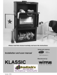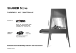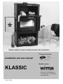
1
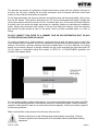
Please read this manual carefully and save the instructions
Tested and Listed by:
Installation and user manual
C
US
Portland
Oregon USA
OMNI-Test Laboratories, Inc.
Manufactured by:
KLASSIC
PO Box 120 Pound Ridge NY
T.914.764.5679 F.914.764.0465
www.wittus.com
Version: 10/09
-
TABLE OF CONTENTS
1. INTRODUCTION ......................................................................................... 2
Safety and Environmental Testing ..........................................................................................3
Features and Items Included...................................................................................................3
2. INSTALLATION .......................................................................................... 3
Precautions .............................................................................................................................3
Specifications ..........................................................................................................................4
Chimney ..................................................................................................................................5
3. SENSIBLE WOOD BURNING .................................................................... 9
Proper wood burning ...............................................................................................................9
Incorrect wood burning............................................................................................................9
Technical information on wood burning...................................................................................9
Types of fuel and heating values...........................................................................................10
Fuel .......................................................................................................................................10
4. OPERATING INSTRUCTIONS ................................................................. 11
First Fire ................................................................................................................................11
Lighting the stove ..................................................................................................................11
Refueling ...............................................................................................................................11
Baking ...................................................................................................................................11
5. TROUBLESHOOTING .............................................................................. 12
6. MAINTENANCE ........................................................................................ 13
Replacing the gasket on the door..........................................................................................13
Replacing the gasket on the glass ........................................................................................13
Disoposal of ashes ................................................................................................................13
Creosote – formation and need for removal..........................................................................13
Interior cleaning.....................................................................................................................13
7. WARRANTY.............................................................................................. 14
8. SPARE PARTS LIST ................................................................................ 14
1. INTRODUCTION
Congratulations on your new KLASSIC wood burning stove/fireplace. As a product of superior
quality and efficiency, we wish you many years of warmth and pleasure.
We are asking you to:
PLEASE READ THIS ENTIRE MANUAL BEFORE YOU INSTALL AND USE YOUR NEW STOVE. FAILURE TO FOLLOW
INSTRUCTIONS MAY RESULT IN PROPERTY DAMAGE, BODILY INJURY, OR EVEN DEATH. KEEP IT HANDY FOR
EASY REFERRAL.
Please take particular note of this symbol:
This indicates special attention.
Version: 10/09
Page 2
Safety and Environmental Testing
The H530 Insert/Firebox for the Klassic has been tested by OMNI-Test Laboratories, Inc. of Portland,
Oregon and is listed to UL 1482 and ULC S628. It is also EPA certified.
Features and Items Included
Your KLASSIC has a built-in convection system, so it creates air circulation in the room to spread the
heat faster and more evenly.
The stove has a small "cool" handle, which enables you to open the door without the use of a glove
(however, always use caution when touching areas where HOT surfaces are located).
Included in the firebox are:
• a thermometer
• an oven mitt
• an easy to use lighter
• a can of touch-up paint (Remove from the stove!)
2. INSTALLATION
Precautions
IF THIS STOVE IS NOT INSTALLED PROPERLY, A HOME FIRE MAY RESULT. TO REDUCE THE RISK, PLEASE
CAREFULLY FOLLOW THE DIRECTIONS FOR INSTALLATION.
First, the stove must be installed according to the directions in this manual. Consult your local Building
Inspector or Fire Marshall before installation about restrictions and installation inspection requirements in
your area. Also, in some areas a "special permit" is required. Not for use in a mobile home.
If utilizing an existing chimney, it is suggested that you have a professional mason or stove installer do a
complete check-up of your chimney, liner, and flue.
In order for the stove to work and draw properly, sufficient air is important! Be especially aware of any
mechanical fans (e.g. kitchen or bathroom) that may affect the proper draw.
When installing the stove, the heat distribution to other rooms should be taken into consideration.
In addition, make sure that the floor and sub-flooring is designed to carry the extra weight of the stove.
A floor plate of non-combustible material (tempered glass floor plates are acceptable) must cover under
the stove and extend 16" (41 cm) (18" (45 cm) in Canada) in front of the stove door, 8" (20 cm) beyond
the sides of the fuel-loading door, and under the pipe and 2" (5 cm) beyond each side for back venting.
In Canada, the 8" (20 cm) floor protection is required beyond the sides of the stove and in the back of the
stove (0" in the back for the US).
The Klassic has a heating capacity of approximately 1,076 ft2 (100m2) based on a standard ceiling
height.
Version: 10/09
Page 3
Specifications
UL 1777 Listed chimney liner (with a 6” (15cm) diameter) up through the block off plate of an existing
masonry chimney, a zero-clearance chimney, or Class A, UL-103 HT, 6” (15cm) diameter chimney
Dimensions (h x w x d) – 60” x 32” x 22” (152cm x 81cm x 56cm)
Firebox Dimensions (h x w x d) – 14” x 24” x 12” (35cm x 60cm x 30cm)
Thermal Output – 20,000 BTU (6 kW); range is 11,100-28,800 BTU
Approximate heating area – 600-1,500ft2
Minimum stove pressure at above output – 15 Pascals
Efficiency – 75%
Tested EPA emission particulate rate – 6.6 grams/hour
Minimum distances from edge of stove to combustible material – as shown below:
Wall View
Corner View
A=
B=
C=
D=
E=
F=
G=
H=
Distance to side wall – 12”(30cm)
Distance to back wall – 17”(43cm)
Corner distance to side walls – 7”(18cm)
Connector pipe to side wall – 25”(64cm)
Connector pipe to back wall – 18”(46cm)
Corner pipe to side walls – 18”(46cm)
Distance to furniture – 36”(92cm)
Front floor protection (to unprotected combustible floor) – US is 16”(41cm); Canada is
18”(46cm)
I = Side floor protection – US is 8”(20cm) from sides of fuel-loading door; Canada is 8”(20cm)
from the sides of the stove
J = Back floor protection – US is 0”(0cm); Canada is 8”(20cm)
Ceiling to top of stove – 36”(92cm)
Ceiling to connector pipe – 18”(46cm)
Note:
A heat shield or protective wall may be used to reduce clearances if approved by the regulatory authority.
Clearances to noncombustible materials are 2” (5cm), but note that “noncombustible” must be solid
cement or block (not brick or tile over combustible material).
Version: 10/09
Page 4
Chimney
The Klassic must be installed using a Class A UL 103 HT approved factory-built chimney system or a
code-approved masonry chimney with a flue liner. In Canada, the installation must conform to NFPA 211
or CAN/CSA-B365. The chimney must extend through the roof at least 3’ (1 m), and 2’ (6 m) above any
structure within 10’ (3 m). The condition of the chimney and height is very important. We recommend a
minimum height of 10’ (3 m) above the stove collar. However, additional chimney height may be required
to maintain adequate draft - consult you dealer.
Note! Mount the special collar using the included hardware. When installing the first piece of pipe (at the
stove), place the pipe inside the collar, that is designed so any moisture or creosote will drip back into the
stove and burn away. Install the remaining stovepipe segments with the crimped end down whenever
possible.
Required Installation Components
A. Chimney cap
B. Insulated chimney
C. Storm collar
D. Roof flashing
E. Ceiling support box or joist shield / firestop
spacer
F. Chimney connector pipe
Chimney connector
Aluminum and galvanized steel pipe is not
acceptable for use with the wood stoves. These
materials cannot withstand the extreme
temperatures of a wood fire and can give off
toxic fumes when heated. Do not use connector
pipe to go through a wall or ceiling.
Each chimney connector or chimney connector
section must be installed to the stove flue collar
and to each other with the male (crimped) end
toward the stove.
A
B
C
D
B
E
F
Version: 10/09
Page 5
This prevents any amount of condensed or liquid creosote from running down the outside of the pipe or
the stove top. All joints, including the flue collar connection must be secured with three sheet metal
screws to ensure that the sections do not separate.
For the best performance the chimney connector should be as short and direct as possible, with no more
than two 90° elbows. The maximum horizontal run is 36" and a recommended total length of single wall
stove pipe connector should not exceed 10 feet. Connector pipe over 10 feet must be double wall from
the stove collar (not mixed with single wall except at a masonry thimble per manufacturer's installation
guide). Always slope horizontal runs upward ¼ inch per foot toward the chimney. Note the connector
pipe should not pass through an attic or roof space, closet or similar concealed space, or a floor or
ceiling.
DO NOT CONNECT THIS STOVE TO A CHIMNEY FLUE OR AIR DISTRIBUTION DUCT OR ANY
SYSTEM SERVING ANOTHER APPLIANCE.
For venting vertically into a Class A chimney, single wall pipe (at least 24 gauge) may be used in the
room where the stove is installed. Refer to the manufacturer’s instructions for the connection to the listed
chimney. The chimney / chimney connector must not be smaller than 6" (15 cm) in diameter. For venting
directly into a masonry chimney or through a thimble, the top of the single wall pipe must be at least 18"
(46 cm) below a combustible ceiling and conform to NFPA 211 or CAN/CSA-B365 guidelines and
methods. See diagram below.
For rear venting or other not listed configurations, consult the local building codes and follow the NFPA
211 or CAN/CSA-B365 guidelines. If the chimney connector is fitted with a baffle, it must be manually
operated, visibly placed for ease of use, and must not close completely. Consult your chimney expert if
you have any questions.
Make sure that there is easy access to the chimney clean-out door.
Read the instructions on the following page carefully before connecting: “Chimney
Connector Systems and Clearances from Combustible Walls for Residential Heating
Appliances”.
Version: 10/09
Page 6
Chimney Connector Systems and Clearances from Combustible Walls for Residential Heating Appliances
Version: 10/09
Page 7
Before installation, it is also important to check that the Vermiculite panels are correctly fitted in the
combustion chamber.
The wood holder in the combustion chamber is not to be removed.
On some baffle plates you will find a metal band. This band is mounted for transport protection only, and
should be removed.
Heat generation and distribution
The Klassic is really two stoves in one. Inside is the actual stove, produced from strong steel plates, and
on the outside a covering of steel. There are two major types of heat: radiant heat and convection heat.
In the airspace between the actual stove
and the covering, convection heat is
generated. The air is drawn in at the
bottom of the firebox.
The heated air then flows upwards and
begins to circulate throughout the room,
subsequently
dispersing
into
the
neighboring rooms, providing perfect
heat distribution.
So the question of where to position
your stove is an important one. The ideal
location is fairly central, in the room
where you require most heat.
Unlike radiant heat, which is highly
concentrated
around
the
stove,
convection heat flows upwards and
spreads to neighboring rooms.
It is very important to ensure that your
chimney has a good draft. Your dealer
or your chimney sweep will be able to
guide and advise you on your chimney
conditions.
Follow the operating instructions and use seasoned wood, which burns easier and cleaner in the
combustion chamber, until a proper draft is obtained. For further information on using wood and lighting
and managing the fire, please refer to sections 3 and 4.
Please note that the stove paint will harden during the first few initial fires.
This means that the stove will generate smoke and an odor of paint, which will dissipate after about an
hour of operation. It is a good idea to ensure effective ventilation during this phase. If ventilation is not
adequate, smoke alarms may be activated. Also, avoid touching the stove during the curing process.
The stove will expand and contract during the lighting and cooling phase, possibly resulting in creaking
noises. This phenomenon is completely normal for steel stoves.
Version: 10/09
Page 8
3. SENSIBLE WOOD BURNING
Proper wood burning
When dry wood is burned in a wood-burning stove the following process occurs (over a period of approx.
1 hour):
- After lighting the log starts to dry and heats up.
- After drying the temperature of wood rises to approx. 300–400°F (150-200°C) and is converted into
combustible gases/charcoal.
- As the wood is gasified a certain portion of the gases produced burn and are converted into carbon
dioxide and water. During this phase the temperature rises to around 1100-1500°F (600-800°C)
and a plentiful supply of air is required. If the air supply is accidentally reduced, the flames will be
smothered, but this will not stop the conversion of the wood into gas. The unburned gas will then
flow out into the chimney, causing a nuisance outdoors and build up of creosote.
- Next-charcoal will burn, which requires very little air supply. Finally, new wood must be laid on the
glowing charcoal cinders.
Warnings - It is extremely important to ensure that you do not overheat your
stove, as this can cause irreparable damage. This kind of damage is not covered
by the warranty. Extremely high combustion temperatures can occur when using
inappropriate fuel, such as kiln-dried wood, coal, pressure-treated wood, scrap
wood.
NEVER USE GASOLINE, GASOLINE-TYPE LANTERN FUEL, KEROSENE, CHARCOAL LIGHTER FLUID,
OR SIMILAR LIQUIDS TO START OR ‘FRESHEN UP’ A FIRE IN THIS HEATER. KEEP ALL SUCH
LIQUIDS WELL AWAY FROM THE HEATER WHILE IT IS IN USE.
HOT WHILE IN OPERATION. KEEP CHILDREN, CLOTHING AND FURNITURE AWAY. CONTACT
MAY CAUSE SKIN BURNS. DO NOT STORE SOLID FUEL WITHIN HEATER INSTALLATION
CLEARANCES OR WITHIN THE SPACE REQUIRED FOR FIRE LIGHTING AND ASH REMOVAL.
Incorrect wood burning
Too much air supplied to the combustion process causes an uncontrollable fire that will heat the entire
stove very rapidly to an extremely high temperature. This can happen if you fire with conditions that
produce an extra-strong draft in the chimney. Never fill the stove completely with wood. It is better to heat
a stove up slowly. This will prevent damage to welds and annealing of the iron. Overfilling the firebox
also substantially reduces the useful life of the vermiculite panels, as cracks are more easily caused. The
log size should be about 2” (5cm) less than the width of the firebox. Start slowly with a “normal” fire from
the bottom, and slowly build it up to a maximum of three logs.
Technical information on wood burning
1 kilo of dry wood is made up of 20% water, with the remaining 80% divided into 60% gas and 20%
charcoal. The 60% gas only contains around half the energy content of the wood, while the 20%
charcoal contains the other half. To achieve optimum combustion, the temperature must reach 11001500°F (600-800°C).
Reload with a few pieces of wood at a time. If too much wood is placed on a layer of embers, the air
supplied will not be sufficient to attain the required temperature, and the gases will disappear out through
the chimney unburned. It is vital to supply air to the fire immediately after adding fuel, so there are flames
in the firebox, and the gases burn. Remember that three logs will burn just as quickly as one. The
quantity of firewood determines the heat emission - the more heat you require, the more wood you
should add at each refueling.
Version: 10/09
Page 9
Types of fuel and heating values
Combustion involves conversion of the fuel from solid form into gases, water vapor and charcoal. The
heating value is an expression of the content of combustible gases - stated in kcal/kg. All wood has
roughly the same heating value per kilogram. The lighter the wood, the more that must be used to
achieve the same heating value as with a heavier species of wood.
Type of wood
Beech and oak
Ash
Maple
Birch
Mountain pine
Fir
Poplar
Dry wood - Lbs./ft3 (Kg/m3)
36.2 (580)
35.6 (570)
33.7 (540)
31.8 (510)
30.0 (480)
24.3 (390)
23.7 (380)
Compare to Beech
100%
98%
93%
88%
83%
67%
65%
As mentioned, air-dried wood contains around 20% water, corresponding to a heating value of approx. 4
kWh/kg equivalent to approx. 3440 kcal/kg (1kW = 860 kcal).
Warning! NEVER burn treated/painted wood, laminated plastic, plywood,
chipboard, refuse, milk cartons, printed matter or similar. Use of such materials
will invalidate your warranty, as this may emit toxic, corrosive and hazardous
fumes when burned. They may also cause a build-up of the toxic gas dioxin,
which is damaging to the stove and the environment.
Fuel
Recently-felled wood contains 60-70% water and must therefore be
seasoned before it can be used in a wood burning stove. It must be cut,
split and air dried, and must contain no more than approx. 25% water
before use. This equates to the wood being left in the open for approx. 1
year - covered only to protect against rain.
It is very important to always use dry wood. Damp wood requires a lot of
air for combustion, as extra energy in the form of heat is needed to dry it
out. Heat emission is therefore minimal.
When wood is burned slowly, it produces tar and other organic vapors,
which combine with expelled moisture to form creosote. The creosote
vapors condense in the relatively cool chimney flue of a slow-burning fire.
As a result, creosote residue accumulates on the flue lining. When
ignited, this creosote makes an extremely hot fire.
The chimney and chimney connector should be inspected at least once
every two months during the heating season to determine if a creosote
buildup has occurred. If creosote has accumulated, it should be removed
to reduce the risk of a chimney fire.
Version: 10/09
Page 10
4. OPERATING INSTRUCTIONS
First Fire
Once your Klassic stove is installed and all instructions have been read, the first fire can be started.
However, please take careful note of the following:
- Your new stove should be broken in gently for top performance and to prevent paint damage,
cracks in the vermiculite or firebox lining, and excessive wear and tear.
- The baffle plate and vermiculite panels may crack under hard impact. These are not covered by
the warranty, so avoid tossing the wood in the firebox.
- Avoid touching the metal during initial fires, as the paint is hardening at this stage. Otherwise this
may mar the paint.
It is a good idea to ensure effective ventilation during the first firing, as the stove will generate smoke and
an odor of paint. The smoke and paint odor will dissipate after about 1 hour’s operation and is not
hazardous to health.
Do not use a grate or elevate the fire – build wood fire directly on hearth.
Lighting the stove
1. Open the outer doors first.
2. Make sure the air vent is in the fully open position (move the handle to the left as shown by the
wide end of a triangle).
3. Add crumbled paper/firelighters and kindling wood to the bottom of the fire box (combustion
chamber). The kindling (about 3 lbs or 1.5 kg) is to be built up crosswise.
4. Light the fire. The door should be ajar for a couple of minutes during the lighting phase.
5. Once the flames have taken a good hold of the kindling, the door can be shut.
6. The air vent should be adjusted down toward the right after approx. 10 minutes (primary air); how
much depends on the chimney draft - however, the air supply must be diminished to the point
where you obtain steady and calm flames.
Once there is a good bed of embers in the stove, you can add wood. It is
important not to open the door while there are flames in the stove, as this may
cause smoke to flow out into the room. Add wood on the basis of your heating
requirements. However, never add more than 4.4 lbs or 2 kg of wood every 1.5–2
hours. Please remember that the exterior surfaces especially the top and front
of the stove in particular will become very hot during burning.
Refueling
1. Open the air vent to the maximum (to the left). To minimize the back draft, the door should be ajar
for about one minute before you open it completely.
2. Open the door slowly. Add 2 – 3 pieces of firewood to the combustion chamber.
3. Close the door.
4. Turn down the air supply (toward the right) when the fire has caught the wood, to obtain steady
and calm flames.
Baking
The upper compartment easily turns into a convenient baking/cooking compartment by closing the upper
baking door, and closing the top louvers on each side of the top of the stove. The natural 2" thick
Brazilian soapstone baking liner provides heat retention and consistent even baking. Use the included
thermometer and have fun. The baking door can also be removed and the area used for warming.
Version: 10/09
Page 11
5. TROUBLESHOOTING
Combustion problems can arise if the combustion conditions are not optimal. This can be corrected by
following the advice given below.
Lighting and burning problems are usually due to wet wood or insufficient
draft.
Version: 10/09
Page 12
6. MAINTENANCE
Gaskets and vermiculite panels are parts which need to be replaced from time to time – depending on
how much you use your stove. In some cases, you may need to replace them every year, while in others,
replacement every second or third year will suffice. As a rule of thumb, gaskets need to be replaced
when it has become flattened and the door no longer fits tightly against the front of the stove. You can
purchase gaskets – with adhesive – from your local dealer.
The vermiculite panels must be replaced when they have worn thin, or when cracks – if any – become so
wide that you can actually see steel through them. If the panels are not replaced at such time, they will
lose their capacity to insulate and reflect heat.
Use only authentic spare parts!
Movable and mechanical parts (closing mechanisms, hinges etc) should be greased once a year with a
heat-resistant lubricant.
You should have your stove checked regularly by a qualified professional to ensure the optimal function
of the stove at all times. Do not make modifications, since any unauthorized changes to the design of the
stove will also invalidate the stove guarantee and test results.
Replacing the gasket on the door
1. Remove the gasket from the inside edge of the door and clean the sealing track (there is no need
to remove the door from the stove).
2. Apply a layer of fire-resistant adhesive to the track where the old gasket was affixed.
3. Press (while stretching it out) the new gasket into the track.
4. Close the door and let the adhesive set for approx. 1 day before opening the door again. If the
adhesive has not hardened sufficiently before the door is opened again, the gasket may fall out.
Replacing the gasket on the glass
1. Open the door.
2. On the inside of the door, in each corner of the glass panel, there is a fastening that must be
loosened so that each fitting can be turned away from the glass panel.
3. Repeat this procedure for all the fittings and remove the glass panel.
4. Remove the old strip from the glass panel.
5. Fit a new gasket around the glass panel.
To replace the glass panel, simply reverse the process described above.
Disoposal of ashes
Ashes should be placed in a metal container with a tight fitting lid. The closed container of ashes should
be placed on a noncombustible floor or on the ground, well away from all combustible materials, pending
final disposal. If the ashes are disposed of by burial in soil or otherwise locally dispersed, they should be
retained in the closed container until all cinders have thoroughly cooled.
Creosote – formation and need for removal
Refer to the Section on Fuel on Page 10. Insure there is sufficient air supply to avoid incomplete
combustion and formation of creosote.
Interior cleaning
Make sure it is possible to access the chimney for sweeping and cleaning.
Version: 10/09
Page 13
7. WARRANTY
The Klassic comes with a 5-year warranty. The warranty covers defects in materials or workmanship.
Any claims during the warranty period should be directed to the dealer who sold the stove. All stoves
from Wittus come with their own individual serial number on the type plate on the top of the firebox.
Record this number and keep it in a safe place. Provide the stove model and serial number to your
dealer in connection with service tasks.
In the event of warranty repairs, a signed and dated invoice must also be produced, showing the dealer’s
name. The warranty does not cover dismantling, transport and reassembly of your stove.
No compensation will be granted for:
- Damage during transport
- Damage to other articles resulting from use of the stove
- Damage arising from misuse, such as overheating. Read the operating instructions carefully to
avoid such problems.
- Damage resulting from a failure to follow the directions in the operating instructions.
Normal wear and tear parts such as vermiculite panels, baffle plates, and gaskets are not covered by the
warranty. Furthermore, glass, ceramic tiles, and soapstone are not covered by the warranty. If any of the
above mentioned need replacing, new parts can be ordered from your dealer.
8. SPARE PARTS LIST
Article No.
413003-00
413004-00
413002-00
413001-00
413000-00
400106-00
Version: 10/09
Article description
Vermiculite bottom panel
Vermiculite baffle plate
Vermiculite rear panel
Vermiculite side panel
Set of 4 vermiculite panels
Glass with gasket
Wood holder
Gasket set with adhesive
Dimensions H x W x D (mm)
305 x 299 x 25
558 x 300 x 28
637 x 247 x 20
430 x 305 x 20
559 x 360 x 4
60 x 43
Page 14