1
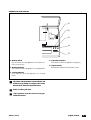
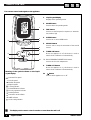
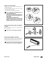
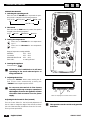
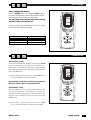
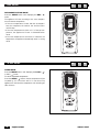
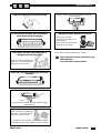
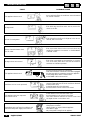
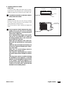
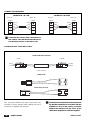
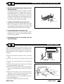
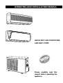
OPERATING AND INSTALLATION MANUAL
SINGLE SPLIT AIR-CONDITIONER
AND HEAT PUMP
a
0
41
R
ce o
Please carefully read this
manual before operating the
appliance.
INDEX
U
I
A
Safety standards
2
U
I
A
Identification of the parts
4
U
I
A
Remote control
6
U
I
A
Operating modes
8
U
I
A
AUTO mode
9
U
I
A
TIMER mode
9
U
I
A
DRY mode
10
U
I
A
SLEEP mode
10
U
I
A
Maintenance
11
U
I
A
Troubleshooting
12
I
A
Installation instructions
13
I
A
Installation of the indoor unit
15
I
A
Installation of the outdoor unit
19
I
A
Venting the air
19
U
I
A
Note
20
U
I
A
Useful information
20
U
User
SINGLE SPLIT
I
Installer
A
Service
English 11/2002
1
SAFETY STANDARDS AND WARNINGS
U
I
A
Use the power supply voltage shown on the rating
plate. Keep the power switch or plug clean. Connect
the power cable correctly and securely to the outlet, avoiding the risk of electric shock or fire due to
insufficient contact.
Check that the outlet is suitable for the plug, otherwise have the outlet replaced. Do not use the
power switch or pull out the plug to switch the
appliance off when operating. This may cause fires
due to sparks, etc.
The user must contact qualified personnel to
earth the appliance, in compliance with the legislation in force, and to install a thermal-magnetic
circuit breaker.
Do not bend, pull or press the power cable, as it
may break. Electric shock or fire are usually caused
by damaged power cables.
The power cable must only be replaced by specialist technicians.
Do not use power supply cables that are too
long, or multiple adapters.
Do not operate the air-conditioner with wet
hands; this may cause electric shock.
Do not block the air inlet or outlet of either the
indoor or outdoor unit.
Extended exposure to cold air is a health risk.
If smoke or a smell of burning is detected, immediately disconnect power and contact the Service
Centre.
Do not modify or alter the characteristics of the
appliance in any way.
Contact the Service Centres authorised by the
Manufacturer for all repairs. Incorrect repair may
cause electric shock, etc.
Make sure the appliance is disconnected from
the power supply when not used for extended periods, and before performing any cleaning or maintenance operations.
Do not install the appliance in environments
where the air may contain gases, oil or sulphur,
or near sources of heat.
Check that the base of the outdoor unit is
installed securely.
This appliance must only be used by adults; do
not allow children to play with the appliance.
Do not climb onto or rest objects on the outdoor unit.
Never insert sticks or tools into the appliance.
This may cause injuries.
2
English 11/2002
SINGLE SPLIT
Lowers
the inside
temperature
by 5°C from
the outside
temperature
Keep the appliance at least 50cm from flammable substances (alcohol, etc.) or from pressurised containers (e.g. spray cans).
Selecting the most suitable temperature will avoid
damaging the appliance.
The direction of air flow must be adjusted correctly. The louvers must be adjusted downwards in
heating mode, and upwards in cooling mode.
Do not leave doors and windows open when the
air-conditioner is operating for long periods.
Do not aim the air stream directly at plants or
animals.
Do not spray water onto the air-conditioner.
This appliance has been designed to air-condition
the home and must not be used for other purposes, such as drying clothes, cooling food, etc.
If the appliance is used in areas without the
renewal of fresh air, precautions must be taken
to prevent any leaks of refrigerant gas from
stagnating in the environment and creating the
risk of fire.
Do not rest heavy or hot objects on the appliance.
The packing materials are recyclable. It is therefore
recommended to place them in suitable containers
for separate waste disposal.
At the end of its working life, take the air-conditioner to a special waste disposal centre.
Only use the air-conditioner as shown in this
booklet. These instructions are not intended to
cover every possible situation that may arise.
Common sense and prudence must be applied
in the installation, operation and conservation of
all household appliances.
※ Working temperature range
Indoor side DB(℃)
SINGLE SPLIT
Outdoor side DB(℃)
Maximum cooling
36
45
Minimum cooling
16
18
Maximum heating
30
27
Minimum heating
16
-10
English 11/2002
3
U
IDENTIFICATION OF THE PARTS
I
A
INDOOR UNIT
2
Air inlet
3
1
4
4
5
11
AUTO
STOP
TEST
RUN
10
Air outlet
AUTO
TEST
RUN
STOP
6
7
8
9
4
AUTO
STOP
4
12
OUTDOOR UNIT
Air inlet
13
1
2
3
4
5
6
7
8
9
10
11
12
13
14
Front panel
Air filter
Electrostatic filter (optional)
Manual switch
Cable panel
Activated carbon filter
Louvers
Signal receiver
LED display
Power plug
Drain hose
Remote control
Handle
Air outlet grill
14
Air outlet
The above figure represents a simplified layout of the appliance and may not correspond to the
appearance of the unit actually purchased.
4
English 11/2002
SINGLE SPLIT
OPERATION AND DISPLAY
1
2
AUTO
TEST
RUN
STOP
3
4
5
1. Manual switch
This is used to start the appliance if the remote control is not working.*
2. Heating indicator
This comes on when the appliance is in heating mode.
4. Operation indicator
This comes on when the appliance is operating.
5. Signal receiver
Receives the signals from the remote control.
3. Cooling indicator
This comes on when the appliance is in cooling
mode.
The shape and the position of the switches and
indicators may change according to the model,
however their functions remain the same.
Power on when grill open.
*This operation must be carried out by specialist technicians.
SINGLE SPLIT
English 11/2002
5
U
REMOTE CONTROL
I
A
The remote control sends signals to the appliance.
1.
Liquid crystal display
Displays all the operating modes.
2.
MODE button
Used to select the operating mode.
3.
FAN button
Used to set the fan speed, in sequence, to automatic,
low, medium, high.
4.
SLEEP button
Used to set or cancel SLEEP mode.
5.
SWING button
Used to start or stop the movement of the vertical
louvers.
6.
TIMER ON button
When the appliance is off, this button is used to
switch the air-conditioner on automatically.
1
3
2
4
5
6
8
7
9
10
Meaning of the symbols shown on the liquid
crystal display:
7-8. ROOM TEMPERATURE SETTING buttons
Used to set the room temperature.
9.
TIMER OFF button
When the appliance is on, this button is used to
switch the air-conditioner off automatically.
10.
button
Used to switch appliance on or off.
Automatic fan speed
Low fan speed
Medium fan speed
High fan speed
Cooling indicator
Dehumidification indicator
Fan only operation indicator
Heating indicator
Automatic mode indicator
SLEEP indicator
Louver swing indicator
The display on the remote control remains on even when the unit is off.
6
English 11/2002
SINGLE SPLIT
HOW TO FIT THE BATTERIES
• Remove the cover of the battery compartment in the
direction of the arrow.
• Fit the new batteries, making sure the (+) and (-) signs
on the battery match correctly.
• Put the cover back on by sliding it into position.
Use 2 x R03 AAA (1.5 V) batteries. Do not
use rechargeable batteries.
Replace the used batteries with new batteries of the same type when the display is no
longer visible.
The batteries last around one year.
The batteries in the remote control must be
disposed of appropriately according to the
legislation in force in the country concerned.
TIPS ON STORING AND USING THE REMOTE
CONTROL
The remote control can be stored in a special support
mounted on the wall.
Remote control holder
The remote control holder is standard
HOW TO USE THE REMOTE CONTROL
To switch the air-conditioner on, aim the remote control
towards the signal receiver. The remote control will work
at a distance of up to 8 metres from the indoor unit.
Store the remote control at least 1m from
television sets or other electrical appliances.
Signal receiver
SINGLE SPLIT
English 11/2002
7
U
OPERATING MODES
I
A
OPERATING MODES
1. Selecting the operating mode
Each time that the MODE button is pressed the operating mode is changed, in the following sequence:
FULL AUTO
COOLING
DRY
FAN ONLY
HEATING
2. FAN mode
Each time that the FAN button is pressed, the speed is
changed, in the following sequence:
AUTO
LOW
MEDIUM
HIGH
3. Setting the temperature
Press once to increase the set temperature
by 1°C.
Press once to decrease the set temperature
by 1°C.
Range of temperature settings available:
HEATING
16°C ~ 30°C
COOLING
16°C ~ 30°C
DEHUMIDIFICATION 16°C ~ 30°C
FAN ONLY
no setting allowed
4. Starting the appliance
Press the button
.
1
3
2
5
3
4
When the unit is switched on it will start
operating in the mode selected prior to
being switched off.
5. Adjusting the air flow
Pressing the “SWING” button starts moving the air
flow louvers start automatically; pressing the
“SWING” button again stops the louvers.
Do not move the vertical air flow louvers
manually, as this may cause poor operation. If
this happens, first turn the appliance off, then
disconnect and reconnect it to the power
supply.
Adjusting the horizontal air flow (manual)
Turn the louver sliders for the horizontal adjustment of
the air outlet to change the angle of the air flow, as shown
(the unit illustrated may be different from the air-conditioner you have purchased).
8
English 11/2002
Sliders for adjusting the horizontal air flow louvers.
This operation must be carried out by specialist
technicians.
SINGLE SPLIT
U
I
A
AUTO MODE
AUTO OPERATING MODES
Press the MODE button until displaying AUTO ( ); in
this mode, the temperature and the fan speed are set automatically based on the actual room temperature.
The operating mode and the temperature setting
depend on the room temperature.
In AUTO mode, the pre-set temperature is 25°C in cooling
mode, while the fan speed may change.
Room temperature
Mode
23°C ~ 26°C
higher than 26°C
Lower than 23°C
FAN ONLY
COOLING
HEATING
U
I
A
TIMER MODE
AUTOMATIC START
After having switched the appliance off, press the T-ON
button to set the time you want the air-conditioner to
switch back on; pressing the T-ON button again increases
the time by 30 minutes, until a maximum of 24 hours from
when the TIMER is set.
E.g.: If the setting is performed at 4 p.m. and the TIMER is set
to 2.5h, the appliance will start at 6.30 p.m.
2.5
When the unit is switched on it will start operating in
the mode selected prior to being switched off.
AUTOMATIC STOP
When the appliance is on, press the T-OFF button to set
the time you want the air-conditioner to switch off;
pressing the T-ON button again increases the time by 30
minutes, until a maximum of 24 hours from when the
TIMER is set.
E.g.: If the setting is performed at 8.30 p.m. and the TIMER
is set to 3.5h, the appliance will switch off at midnight.
SINGLE SPLIT
English 11/2002
9
DRY MODE
U
I
A
U
I
A
DEHUMIDIFICATION MODE
Press the MODE button until displaying the DRY ( )
mode.
The appliance will start according to the room temperature and the set temperature:
• If the room temperature is lower than the set temperature, the compressor, the outdoor unit and the indoor
unit will stop.
• If the room temperature is within ± 2°C of the set temperature, the appliance will start in dehumidification
mode.
• If the room temperature is more than 2°C above the set
temperature, the appliance automatically starts in cooling
mode.
SLEEP MODE
SLEEP MODE
Press the MODE button until displaying the COOL ( )
or DRY ( ) mode.
To set the requested temperature.
Press the SLEEP ( ): button: the set temperature will be
increased by 1°C in one hour and 2°C in two hours. The
appliance will then hold the temperature until switching off
(after 6 hours).
10
English 11/2002
SINGLE SPLIT
U
I
A
MAINTENANCE
Unplug the appliance from the power outlet
Replace the filters with the side marked as “FRONT”
facing the outside
To remove the front panel, pull it outwards, as
shown by the arrows in the figure
Installation of the activated carbon filters*
Clean with a soft damp cloth, using water or
detergent, then dry in the shade.
- Remove the air filters
- Remove the new filters from
the packaging
- Insert them in the special slots
- Reposition the air filters
The air filters should be cleaned every 3 weeks
These operations must be performed by specialist technicians.
* The carbon filters can’t be washed.
Never use water at temperatures
above 45°C, as the panel may be
deformed or fade in colour.
Insert the front panel as shown by the arrows in
the figure
Cleaning the air filters
Slot
Air filter
Open the front panel, grip the filter and lift it slightly,
then remove it.
Never use water at temperatures
above 45°C, as the panel may be
deformed or fade in colour.
To remove dust from the filter, use a vacuum cleaner or
wash the filter in water and then leave it to dry in the shade.
SINGLE SPLIT
English 11/2002
11
U
TROUBLESHOOTING
FAULT
I
A
POSSIBLE CAUSE
Wait
The appliance doesn't work
• Once switched off the air-conditioner cannot be started
for around 3 minutes
Strange smell
• This smell may come from other sources, such as furniture or the like.
Sound of running water
• This derives from the flow of refrigerant in the air-conditioner, and is not a fault.
Sprays of atomised water from
the air outlet
• This occurs when the air in the room cools down very
quickly, for example in “COOLING” or “DEHUMIDIFICATION” mode.
Strange noises can be heard
• This noise is produced by the expansion or contraction of the front panel due to the thermal variations,
and does not indicate a problem.
The appliance doesn't work
• Are the protection devices or fuses faulty?
• Have the connections come loose or the cable unplugged?
• At times operation is stopped to protect the appliance.
• Is the voltage above 244V or below 206V?
• Is the TIMER-ON functions active?
OFF
Insufficient cold or hot air produced
• Is the temperature suitably set?
• Are the outlets and inlets of the air-conditioner blocked?
• Is the air filter dirty?
• Is the fan speed set to the minimum?
• Are there other sources of heat in the room?
The appliance does not respond to
the remote control
• Is the remote control near the indoor unit?
• Are the batteries in the remote control flat?
• Are there obstacles between the remote control and
the signal receiver on the indoor unit?
Immediately switch off the air-conditioner and
disconnect the power supply in the event of:
12
English 11/2002
• Strange noises during operation.
• Faulty fuses or switches.
• Sprays of water or objects inside the appliance.
• Hot cables or plugs.
• Very strong smell coming from the appliance.
SINGLE SPLIT
I
A
INSTALLATION INSTRUCTIONS
INSTALLATION DIAGRAM
The distance from the ceiling must be
greater than 150mm
The distance from the
wall must be greater
than 150mm
The distance from
the wall must be
greater than 150mm
Flexible sleeve
Insulation tape
The clearance of the
air outlet must be at
least 300mm
The distance from the floor
must be greater than 2500mm
The distance from the
wall must be greater
than 500mm
The distance between
the air inlet and the
wall must be greater
than 300mm
The distance from the
wall must be greater
than 300mm
The distance from the
wall must be greater
than 500mm
6
28
The distance of the air
outlet from the wall
must be greater than
2000mm
540
The above figure represents a simplified layout of the appliance and may not correspond
to the appearance of the unit actually purchased.
SINGLE SPLIT
English 11/2002
13
SELECTING THE BEST SITE
Suitable places for installation of the indoor unit
• Absence of obstacles near the air outlet so that the air
can flow freely around the room.
• Places where it is easy to make holes in the wall and lay
the pipes.
• Observe the distances from the ceiling and from the wall
indicated in the wiring diagram.
• Places where the air filter can be removed easily.
• Place the unit and the remote control 1 metre or more
from television sets, radios, etc.
• Keep the appliance as far away as possible from fluorescent lamps, to prevent harmful effects.
• Do not place objects near the air inlet, so as not to
block it.
• In a site that can support the weight and not increase
the operating noise and vibrations.
Indoor unit
Height less than 5m
Maximum length of the
pipe 15m
Outdoor unit
The appliance shall not be installed in the laundry.
Outdoor unit
Minimum installation height of the indoor
unit (Min. 2.5m).
Height less than 5m
Places suitable for the installation of the outdoor unit
• Install the unit in a suitable and well-ventilated site; avoid
installing it in places where there are possible leaks of
combustible gases.
• Observe the distance indicated from the wall.
• Do not install the outdoor unit in areas that are dirty or
greasy, near gas emissions from vulcanisation or very
salty sea areas.
• Avoid installing the unit on the side of a road where it
may come into contact with muddy water.
• On a fixed base that does not increase the operating
noise.
• In a place where the air outlet is not blocked.
Maximum length of
the pipe 15m
Indoor unit
The unit must not be started before having
been completely assembled in its place of
operation.
The installation and maintenance of the
equipment must be carried out exclusively
by qualified technicians.
The appliance must be installed according to
the legislation in force in the country concerned.
Before starting the appliance, check that it is
correctly earthed, according to the legislation in force in the country concerned.
14
English 11/2002
SINGLE SPLIT
I
A
INSTALLATION OF THE INDOOR UNIT
1. INSTALLATION OF THE FASTENING PLATE
Select the position for installing the fastening plate,
according to of the location of the indoor unit and the
layout of the pipes.
Adjust the level of the fastening plate, using a straightedge or a plumb line.
Make 32mm deep holes in the wall to mount the plate.
Insert the plastic plugs in the holes, then secure the fastening plate using the self-threading screws supplied
with the unit.
Check that the fastening plate is securely fitted so as to
support a 60kg adult.
3. INSTALLATION OF THE PIPES ON THE
INDOOR UNIT
Place the pipes (for liquid and gas) through the hole in
the wall from the outside, or alternatively from the
inside after having completed the installation of the
pipes and the connection of the cables on the indoor
unit, for connection to the outdoor unit.
Decide whether to remove the plastic segment,
according to the direction of the pipes.
When the pipe is fastened along the direction 1, 2 or 4, remove the corresponding plastic segment from the base of the indoor unit.
INSIDE
2. MAKE A HOLE FOR THE PIPES
Choose the location of the hole for the pipes, according to the position of the fastening plate.
Make a hole in the wall. The hole must slope downwards towards the outside.
Place a sleeve through the hole in the wall to protect
the wall and keep it clean.
OUTSIDE
Your fastening plate may differ from the one
described above, yet the installation procedure is the same.
Sleeve with hole in the wall
(rigid polythene pipe supplied by the user)
5mm (downwards
slope)
Direction of pipe insertion
Raceway
Plastic
segment
4
1
Remove the plastic
segment along the
raceway
3
2
After having connected the pipes according to the
instructions, install the drain hose.Then install the power supply cables. After having completed the connections, wrap the pipes, cables and drain hose in a layer of
thermal insulation.
Thermal insulation
Line the joints of the pipe with thermal insulation and cover them with vinyl tape.
Vinyl tape covering
SINGLE SPLIT
English 11/2002
15
Thermal insulation lining
• Position the drain hose under the pipes.
• Insulation material: polythene foam, thickness greater
than 6mm.
Power cable
Drain hose
Control cable
Connection cables
The drain hose must be supplied by the user.
• The drain hose must run downwards, to assist drainage.
• Do not bend the drain hose, allow it to protrude, twist it
or immerse the end in water. If the drain hose is connected to an extension, check that this is thermally insulated when running in the indoor unit.
• If the pipes run to the right, the pipes, the power cable
and the drain hose must be thermally insulated and fastened to the rear of the unit by a pipe coupling.
1. Insert the pipe coupling in the opening.
2. Press the pipe coupling to secure it to the base.
Insulation tape
Pipe coupling
Base
Connecting the pipes
• Connect the pipes to the indoor unit using two spanners. Pay careful attention to the torque specified below
to avoid deforming and damaging the pipes, connectors
and countersunk nuts.
• First tighten by hand, and then use the spanners.
Model
Pipe dimensions
Torque
Nut
7-9-12-17,3 K
23,5 K
7-9 K
12-17,3 K
23,5 K
Liquid side (ø 6 o 1/4")
Liquid side (ø 10 o 3/8")
Gas side (ø 10 o 3/8")
Gas side (ø 12 o 1/2")
Gas side (ø 16 o 5/8")
1,8 Kg.m
3,5 Kg.m
3,5 Kg.m
5,5 Kg.m
7,5 Kg.m
17 mm
22 mm
22 mm
24 mm
27 mm
Model
Q/m (1)
7 - 9 - 12 - 17,3 K
23,5 K
10 g/m
20 g/m
(1) Quantity of refrigerant for each metre of pipe over the
5 m.
16
English 11/2002
Insert here
Large
pipe
Drain
hose
Small
pipe
Pipe coupling
Base
Large
pipe
Drain
hose
Small
pipe
Fasten here
Base
SINGLE SPLIT
3. CONNECTING THE CABLE
Indoor unit
Connect the power cable to the indoor unit by connecting the wires to the terminals on the control panel individually, according to the connection to the outdoor unit.
Front panel
Terminal (inside)
Console
To make the connection to the indoor unit terminal, remove the console.
Indoor unit
Frame
Outdoor unit
Remove the access door from the unit by loosening
the screw. Connect the wires to the terminal on the
control panel with a terminal screw.
Place the access door back in position and tighten the
screw.
Use an approved switch between the power
supply source and the unit. An isolating
device must be fitted to correctly disconnect
all the power supply lines.
Use a separate power supply circuit specifically for the air-conditioner. For details on
the wiring method, refer to the circuit diagram inside the access door.
Check that the thickness of the cable complies with the specifications of the power
supply.
Check the wires and make sure that they are
all securely fastened following the connection of the cable.
Make sure an ear th leakage switch is
installed in wet or damp areas.
The connection cable between the outdoor
and indoor unit must be suitable for outdoor
use.
The plug must remain accessible following
the installation of the appliance, so that the
appliance can be unplugged if required. If this
is not possible, connect the appliance to a
two-pole switch, with a distance between the
contacts of at least 3mm, which must be
installed in an accessible position.
SINGLE SPLIT
Access door
fastener (inside)
Outdoor unit
English 11/2002
17
CONNECTION DIAGRAM
MODELS 7K - 9K -12K
Indoor unit
MODELS 17.3K-23.5K
Outdoor unit
Indoor unit
Terminal
Terminal
Terminal
Yellow/Green
Yellow/Green
3
Brown
2
1N
Brown
Power cable
Blue
Blue
Outdoor unit
Terminal
Yellow/Green
Yellow/Green
3
3
2
1N
2
1N
Brown
Brown
Red
Red
Power cable
Blue
Blue
3
2
1N
Check that the colours of the connections on
the outdoor unit and the terminal block are
not the same as those on the indoor unit.
OUTDOOR UNIT CONTROL CABLE
Models 7K-9K-12K-17,3K-23,5K
(inside)
(outside)
Quick connectors
Models 7K-9K
Models 12K-17,3K-23,5K
PFor connections between the indoor and outdoor unit
exceeding 5 metres (standard cable supplied), two quick
connectors are supplied (see the figure).
18
English 11/2002
All the electrical connections must be performed
by specialist technicians, in accordance with the
legislation in force in the country concerned.
Respect the sequence and the colour of the
cables when using the two connectors supplied.
SINGLE SPLIT
I
A
INSTALLATION OF THE OUTDOOR UNIT
1. Install the drain fitting and the drain hose (heat
pump model only)
The condensate is drained from the outdoor unit when
the appliance operates in heating mode. To avoid disturbing neighbours and to respect the environment,
install a drain fitting and a drain hose to convey the
condensate. Simply install the drain fitting and the rubber washer on the chassis of the outdoor unit, then
connect a drain hose as shown in the figure.
Washer
Drain fitting
2. Installation and fastening of the outdoor unit
Bolt the unit securely to a level and sturdy floor. If the
unit is to be installed on a wall or on the roof, make
sure the support is fastened securely to prevent it from
moving following intense vibrations or strong winds.
Drain hose
(supplied by the
user)
3. Connecting the pipe to the outdoor unit
Remove the cap from the 2- and 3-way valves. Connect
the pipes to the 2- and 3-way valves separately, tightening to the torque specified.
4. Connecting the cable to the outdoor unit (see
the previous page)
I
A
VENTING THE AIR
The air that contains moisture remaining inside the refrigerant circuit may cause problems to the compressor. After
having connected the indoor and outdoor unit, vent the air
and the moisture from the refrigerant circuit using a vacuum pump.
(1) Unscrew and remove the caps from the 2- and 3-way
valves.
(2) Unscrew and remove the cap from the service valve.
Vacuum pump
(3) Connect the vacuum pump hose to the valve being
used.
(4) Run the vacuum pump for 10-15 minutes, until reaching
an absolute depression of 10mm Hg.
(5) With the vacuum pump still on, close the low pressure
knob on the vacuum pump hose.Then stop the vacuum
pump.
(6) Open the 2-way valve a 1/4 of a turn, then close it
again after 10 seconds. Check the seal of all the joints
using liquid soap or an electronic leak detector.
(7) Turn the body of the 2- and 3-way valves. Disconnect
the vacuum pump hose.
(8) Reposition and tighten all the caps on the valves.
SINGLE SPLIT
indoor unit
Refrigerant flow direction
3-way valve
Service
port
(2) Turn
(8) Tighten
2-way valve
(6) Open 1/4 turn
(7) Turn to fully open the valve
(7) Turn to fully open the
valve cap
(1) Turn
valve
(8) Tighten
(1) Turn
Valve cap
(8) Tighten
Connect to outdoor unit
English 11/2002
19
U
NOTES
• Read this manual before installing and use the appliance.
• Check that air does not enter the refrigerant system and
that there are no leaks of refrigerant when the air-conditioner is moved.
• Run a test cycle after the installation of the air-conditioner and record the operating data.
• The type of fuse installed on the indoor control unit is
rated to 3.15A,T, 250V.
• The user must fit the entire unit with a fuse suitable for
the maximum input current or use another safety cutout device.
I
A
• The plug must remain accessible following the installation
of the appliance, so that the appliance can be unplugged if
required.
If the supply cord is damaged, it must be replaced by the
manufacturer or its service agent or a similarly qualified
person in order to avoid a hazard.
USEFUL INFORMATION
U
I
A
For information on service and the supply of spare parts, please contact:
FIXED AIR-CONDITIONING TECHNICAL SERVICE DEPARTMENT
DE’ LONGHI GROUP
via L. Seitz,47 - 31100 Treviso (ITALY)
Numero Verde
800 019 190
20
English 11/2002
SINGLE SPLIT