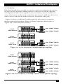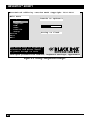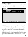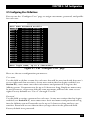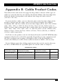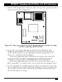
1
JANUARY 2003 Customer Support Information: FREE tech support 24 hours a day, 7 days a week: Call 724-746-5500 or fax 724-746-0746. Mailing address: Black Box Corporation, 1000 Park Dr., Lawrence, PA 15055-1018 World-Wide Web: www.blackbox.com • E-mail: [email protected] © Copyright 2003. Black Box Corporation. All rights reserved. KV130A KV130DA KV131A-R2 KV132A-R2 KV134A-R2 KV138A KV138DA KV139A KV139DA THE SERVSWITCH™ FAMILY Welcome to the ServSwitchTM Family! Thank you for purchasing a BLACK BOX® ServSwitch™ Brand KVM switch! We appreciate your business, and we think you’ll appreciate the many ways that your new ServSwitch keyboard/video/mouse switch will save you money, time, and effort. That’s because our ServSwitch family is all about breaking away from the traditional, expensive model of computer management. You know, the one-sizefits-all-even-if-it-doesn’t model that says, “One computer gets one user station, no more, no less.” Why not a single user station (monitor, keyboard, and mouse) for multiple computers—even computers of different platforms? Why not a pair of user stations, each of which can control multiple computers? Why not multiple user stations for the same computer? With our ServSwitch products, there’s no reason why not. We carry a broad line of robust solutions for all these applications. Do you have just two PCs, and need an economical alternative to keeping two monitors, keyboards, and mice on your desk? Or do you need to share dozens of computers, including a mix of IBM® PC, RS/6000®, Apple® Macintosh®, Sun Microsystems®, and SGI® compatibles among multiple users with different access levels? Does your switch have to sit solidly on a worktable and use regular everyday cables? Or does it have to be mounted in an equipment rack and use convenient many-to-one cables? No matter how large or small your setup is, no matter how simple or how complex, we’re confident we have a ServSwitch system that’s just right for you. The ServSwitch™ family from Black Box—the one-stop answer for all your KVMswitching needs! * This manual will tell you all about your new ServSwitch™ Affinity, including how to install, operate, and troubleshoot it. For an introduction to the ServSwitch Affinity, see Chapter 2. The ServSwitch Affinity product codes covered in this manual are: KV130A KV131A-R2 KV132A-R2 KV134A-R2 KV138A KV139A KV130DA KV138DA KV139DA This manual also includes information about the Affinity’s Port Cards, Terminator Card, Expansion Cards, and Rackmount Kits, but these come with their own installation guides. Their product codes are: KV1300C KV1301C-R2 KV1304C KV1305C KV1306C RMK19A RMK19A139 RMK23A RMK23A139 RMK24A RMK24A139 1 SERVSWITCH™ AFFINITY TRADEMARKS USED IN THIS MANUAL BLACK BOX and the logo are registered trademarks, and ServSwitch and ServSwitch Affinity are trademarks, of Black Box Corporation. Apple, Mac, and Macintosh are registered trademarks of Apple Computer, Inc. IBM, PC/AT, PS/2, RS/6000, and ThinkPad are registered trademarks, and PC/XT is a trademark, of International Business Machines Corporation. Microsoft, HyperTerminal, IntelliMouse, Windows, and Windows NT are registered trademarks or trademarks of Microsoft Corporation in the United States and/or other countries. Sun and Sun Microsystems are registered trademarks of Sun Microsystems, Inc. in the United States and other countries. Any other trademarks mentioned in this manual are acknowledged to be the property of the trademark owners. 2 FCC/IC STATEMENTS FEDERAL COMMUNICATIONS COMMISSION AND INDUSTRY CANADA RADIO-FREQUENCY INTERFERENCE STATEMENTS This equipment generates, uses, and can radiate radio-frequency energy and if not installed and used properly, that is, in strict accordance with the manufacturer’s instructions, may cause interference to radio communication. It has been tested and found to comply with the limits for a Class A computing device in accordance with the specifications in Subpart B of Part 15 of FCC rules, which are designed to provide reasonable protection against such interference when the equipment is operated in a commercial environment. Operation of this equipment in a residential area is likely to cause interference, in which case the user at his own expense will be required to take whatever measures may be necessary to correct the interference. Changes or modifications not expressly approved by the party responsible for compliance could void the user’s authority to operate the equipment. This digital apparatus does not exceed the Class A limits for radio noise emission from digital apparatus set out in the Radio Interference Regulation of Industry Canada. Le présent appareil numérique n’émet pas de bruits radioélectriques dépassant les limites applicables aux appareils numériques de la classe A prescrites dans le Règlement sur le brouillage radioélectrique publié par Industrie Canada. 3 SERVSWITCH™ AFFINITY EUROPEAN UNION DECLARATION OF CONFORMITY This equipment complies with the requirements of the European EMC Directive 89/336/EEC with respect to EN55022 (Class B), EN50082-1/EN60555-2, and the Low Voltage Directive. 4 NOM STATEMENT NORMAS OFICIALES MEXICANAS (NOM) ELECTRICAL SAFETY STATEMENT INSTRUCCIONES DE SEGURIDAD 1. Todas las instrucciones de seguridad y operación deberán ser leídas antes de que el aparato eléctrico sea operado. 2. Las instrucciones de seguridad y operación deberán ser guardadas para referencia futura. 3. Todas las advertencias en el aparato eléctrico y en sus instrucciones de operación deben ser respetadas. 4. Todas las instrucciones de operación y uso deben ser seguidas. 5. El aparato eléctrico no deberá ser usado cerca del agua—por ejemplo, cerca de la tina de baño, lavabo, sótano mojado o cerca de una alberca, etc. 6. El aparato eléctrico debe ser usado únicamente con carritos o pedestales que sean recomendados por el fabricante. 7. El aparato eléctrico debe ser montado a la pared o al techo sólo como sea recomendado por el fabricante. 8. Servicio—El usuario no debe intentar dar servicio al equipo eléctrico más allá a lo descrito en las instrucciones de operación. Todo otro servicio deberá ser referido a personal de servicio calificado. 9. El aparato eléctrico debe ser situado de tal manera que su posición no interfiera su uso. La colocación del aparato eléctrico sobre una cama, sofá, alfombra o superficie similar puede bloquea la ventilación, no se debe colocar en libreros o gabinetes que impidan el flujo de aire por los orificios de ventilación. 10. El equipo eléctrico deber ser situado fuera del alcance de fuentes de calor como radiadores, registros de calor, estufas u otros aparatos (incluyendo amplificadores) que producen calor. 11. El aparato eléctrico deberá ser connectado a una fuente de poder sólo del tipo descrito en el instructivo de operación, o como se indique en el aparato. 5 SERVSWITCH™ AFFINITY 12. Precaución debe ser tomada de tal manera que la tierra fisica y la polarización del equipo no sea eliminada. 13. Los cables de la fuente de poder deben ser guiados de tal manera que no sean pisados ni pellizcados por objetos colocados sobre o contra ellos, poniendo particular atención a los contactos y receptáculos donde salen del aparato. 14. El equipo eléctrico debe ser limpiado únicamente de acuerdo a las recomendaciones del fabricante. 15. En caso de existir, una antena externa deberá ser localizada lejos de las lineas de energia. 16. El cable de corriente deberá ser desconectado del cuando el equipo no sea usado por un largo periodo de tiempo. 17. Cuidado debe ser tomado de tal manera que objectos liquidos no sean derramados sobre la cubierta u orificios de ventilación. 18. Servicio por personal calificado deberá ser provisto cuando: A: El cable de poder o el contacto ha sido dañado; u B: Objectos han caído o líquido ha sido derramado dentro del aparato; o C: El aparato ha sido expuesto a la lluvia; o D: El aparato parece no operar normalmente o muestra un cambio en su desempeño; o E: El aparato ha sido tirado o su cubierta ha sido dañada. 6 TABLE OF CONTENTS Contents Chapter Page 1. Specifications ........................................................................................... 11 2. Introduction ............................................................................................. 2.1 The Complete Package ..................................................................... 2.2 Features ............................................................................................. 2.3 The Rear Panel Illustrated ............................................................... 2.4 Cable Requirements ......................................................................... 2.5 Equipment Requirements ................................................................ 15 15 16 19 22 22 3. Installation and Preconfiguration ............................................................ 3.1 Quick Setup Guide ........................................................................... 3.2 Guidelines for Using the ServSwitch Affinity with Your Equipment .. 3.2.1 CPUs ....................................................................................... 3.2.2 Mouse and Keyboard ............................................................ 3.2.3 Monitor .................................................................................. 3.3 Installation Procedure ...................................................................... 3.3.1 Placement .............................................................................. 3.3.2 Setting and Installing Cards ................................................. 3.3.3 Rackmounting (Optional) .................................................... 3.3.4 Connecting the Monitors, Keyboards, and Mice ................ 3.3.5 Connecting CPUs .................................................................. 3.3.6 Connecting Devices’ Serial Ports (Optional) ...................... 3.3.7 Connecting Other Affinity Units (Optional) ...................... 3.3.8 Powering Up the Affinity Units ............................................ 3.3.9 Changing the Keyboard Setting of Windows NT 4.0 CPUs ... 3.3.10 Switching and Accessing the Display from the Keyboard ... 3.4 Daisychaining ServSwitch Affinity Units .......................................... 3.4.1 Expansion Cabling ................................................................ 3.4.2 Bus and User-Port (KVM) Numbering ................................ 3.4.2.A In 4-User Models ...................................................... 3.4.2.B In 8-User and 16-User Models ................................ 3.4.3 Topologies ............................................................................. 3.4.3.A Regular Bus .............................................................. 3.4.3.B Split Bus .................................................................... 3.4.3.C Ring .......................................................................... 3.4.4 Mixed Chains ......................................................................... 23 23 24 24 24 27 30 30 31 31 31 32 33 34 34 35 35 36 36 37 37 37 40 40 43 45 47 7 SERVSWITCH™ AFFINITY Contents (continued) Chapter 3. Page Installation and Preconfiguration (continued) 3.5 The Power-Up Procedure ................................................................. 3.5.1 The Power-Up Diagnostic Screen: Standard Messages ....... 3.5.2 Kernel-Halt Error Messages .................................................. 3.5.3 Kernel Serial-Port Messages .................................................. 3.6 Initial Configuration ......................................................................... 3.6.1 Initially Configuring a Single Unit ....................................... 3.6.2 Initially Configuring Multiple Daisychained Units ............. 48 49 51 54 55 55 56 4. Full Configuration ................................................................................... 4.1 Using the Menu ................................................................................ 4.1.1 Navigating the Configuration Pages .................................... 4.1.2 Choosing Names ................................................................... 4.1.3 Saving Configuration Changes ............................................. 4.2 Configuring the System .................................................................... 4.2.1 System Settings ...................................................................... 4.2.2 Keyboard Settings .................................................................. 4.2.3 Appearance ............................................................................ 4.3 Configuring Computers ................................................................... 4.4 Configuring User Stations ................................................................ 4.5 Configuring User Definitions ........................................................... 4.6 Configuring User Profiles ................................................................. 4.7 Configuring Groups .......................................................................... 4.8 The Status Page ................................................................................. 58 59 59 59 59 61 61 62 63 65 69 71 72 75 77 5. On-Screen Functions, Same-Slot Users, and Connection Modes ......... 5.1 Logging In ......................................................................................... 5.2 Connection-Status Messages ............................................................. 5.2.1 “Connection Successful” ....................................................... 5.2.2 “Connection Failed” .............................................................. 5.2.3 Disconnect Status .................................................................. 5.3 User Stations Attached to Same-Numbered Slots/Buses ............... 5.4 Connection Modes ............................................................................ 5.4.1 View Mode ............................................................................. 5.4.2 Share Mode ........................................................................... 5.4.3 Control Mode ........................................................................ 5.4.4 Private Mode .......................................................................... 5.4.5 Connection-Mode Behavior ................................................. 79 79 80 80 80 82 84 86 86 86 86 87 87 8 TABLE OF CONTENTS Chapter Page 6. Keyboard Commands .............................................................................. 6.1 Command Summary ....................................................................... 6.2 Display Configuration Menu: [Ctrl] [F12] .................................... 6.3 Display CPU List: [Ctrl] [Esc] ........................................................ 6.4 Select Computer: [Ctrl] xxxx [Enter] ............................................ 6.5 Switch to the Next Port in Sequence: [Ctrl] [+] ........................... 6.6 Switch to the Previous Port in Sequence: [Ctrl] [–] ..................... 6.7 Switch to the Prior Port: [Ctrl] [←] or [Ctrl] [Backspace] ......... 6.8 Display User-Station Status: [Ctrl] D ............................................. 6.9 Log Out: [Ctrl] L ............................................................................ 6.10 Disconnect: [Ctrl] Q ....................................................................... 6.11 Reset Keyboard and Mouse: [Ctrl] R ............................................. 6.12 Reset/Enable Mouse in Windows NT and UNIX: [Ctrl] O ......... 6.13 Send Null Byte to PS/2 Type Mouse: [Ctrl] N .............................. 6.14 Identify Firmware Revision: [Ctrl] I ............................................... 6.15 Start Scan: [Ctrl] S .......................................................................... 6.16 End Scan: [Ctrl] X .......................................................................... 6.17 Pass This Command Through: [Ctrl] X or [Ctrl] [Tab] .............. 88 88 90 90 91 91 91 91 92 92 92 92 93 93 94 94 95 95 7. Using the Dedicated Serial Ports ............................................................ 96 7.1 Basic Setup: Establishing a Serial Connection ................................ 96 7.2 The Serial Options Menu ................................................................. 97 7.2.1 Option 1. Change Starting Computer ................................. 98 7.2.2 Option 2. Change Serial Port Baud Rate (Data Rate) ........ 98 7.2.3 Option 3. Receive New Kernel or Main Program (Upgrade Firmware) .......................................................... 99 7.2.4 Options 4 and 5. Send Main Program/Send Kernel (Distribute Upgraded Firmware) .................................... 101 7.2.5 Option 6. Reset to Factory Defaults ................................... 102 7.2.6 Option 7. Save Changes ...................................................... 102 7.2.7 Option 8. Exit and Restart Unit ......................................... 103 8. Using the CPU Ports as Serial Ports ...................................................... 104 9. Troubleshooting .................................................................................... 9.1 Common Problems ......................................................................... 9.2 Replacing a Power Supply in a Dual-Powered Affinity ................. 9.3 Calling Black Box ............................................................................ 9.4 Shipping and Packaging ................................................................ 106 106 112 112 112 9 SERVSWITCH™ AFFINITY Contents (continued) Appendix Page Appendix A: NVRAM Factory Defaults ....................................................... 113 Appendix B: Cable Product Codes .............................................................. 115 Appendix C: Pinout of the Dedicated Serial Ports ..................................... 118 Appendix D: The LK461 Keyboard ............................................................. 119 Appendix E: Installing Cards in the ServSwitch Affinity ............................ E.1 Adding a Port Card ......................................................................... E.2 Installing or Swapping In a Terminator Card (4-User Chassis Only) .................................................................. E.3 Setting the RING/BUS Jumper on an Expansion Card ............... E.4 Setting the JP1 and JP2 (User-Number) Jumpers on 8-Port Expansion Cards ............................................................... E.4.1 Setting JP1 and JP2 on a Card That Will Be Installed in an 8-User Affinity ......................................................... E.4.2 Setting JP1 and JP2 on a Pair of Cards That Will Be Installed in a 16-User Affinity ......................................... E.5 Installing or Swapping In an Expansion Card .............................. 120 120 121 122 123 123 123 125 Appendix F: Upgrading a Non-R2 Affinity with -R2 Serial Features ......... 126 Appendix G: Rackmounting the Affinity .................................................... 129 10 CHAPTER 1: Specifications 1. Specifications Hardware Required: Monitor that supports your computers’ highest video standard; in multiplatform applications, should be a multisync model capable of forming video from either composite sync or separate horizontal and vertical sync signals (see Section 3.2.3) Compliance: CE, FCC Part 15 Subpart B Class A, IC Class/classe A Standards: With original Serv cabling: VGA (color or monochrome/ page white) video; With original Serv cabling (minimal) or coaxial cabling (recommended): SVGA and (with KV99MA adapter) Mac video; With coaxial cabling: XGA (color or monochrome), Sun, RS/6000, or SGI video Interfaces: On CPU and user ports of Port Cards and IN 1 and OUT 1 ports on primary Expansion Cards: Proprietary composite of: • IBM PS/2, PC/AT, or Sun compatible keyboard; • PS/2, RS-232, or Sun compatible mouse; and • Video (standards listed above); With the KV99MCON adapter, also supports ADB (Mac compatible) keyboard and mouse ports; The CPU ports can also carry serial data to and from serial devices; The IN 1 and OUT 1 ports also carry system-control information; On Expansion Cards’ other IN and OUT ports: Proprietary video composite (standards listed above); On serial ports of Port Cards: EIA/TIA RS-232 proprietarily pinned on RJ-12 (“6-wire RJ-11”) connectors, DTE Resolution: Up to 1280 x 1024, but refer to Section 3.2.3 Protocol: RS-232: Asynchronous Data Format: RS-232: 8 data bits, 1 stop bit, no parity (fixed) 11 SERVSWITCH™ AFFINITY Data Rate: RS-232: User-selectable: On serial ports: 9600 or 57,600 bps; On CPU ports: 50, 110, 300, 600, 1200, 2400, 4800, or 9600 bps Flow Control: RS-232 on CPU ports: Transparent to software flow control; doesn’t support hardware flow control Maximum Distance: 20 ft. (6.1 m) of CPU or User Cable—possibly as much as 100 ft. (30.5 m) of coaxial CPU or User Cable, depending on CPUs, monitor, and video resolution (see Section 3.2.3)—from any Affinity Port Card to any device attached to it except serial devices; 100 ft. (30.5 m) of Expansion Cable between any two Affinity units or from an Affinity to a Matrix ServSwitch; 50 ft. (15.2 m) of serial cable from the RS-232 port of any Affinity Port Card to a computer’s serial port; 100 ft. (30.5 m) of serial cable from the CPU port of any Affinity Port Card to a device’s serial port User Controls: For system: Keyboard commands and on-screen menus; On Affinity chassis: Rear-mounted ON/OFF rocker switch(es): KV130DA, KV138DA, KV139DA: (2); All other models: (1); On all Expansion Cards (KV1305C and KV1306C): Board-mounted BUS/RING jumper; On 8-User Expansion Cards (KV1306C): (2) Board-mounted jumpers for user-port numbering Indicators: All models: ON/OFF switch(es) are dark when ServSwitch Affinity is OFF, backlit when Affinity is ON; KV130DA, KV138DA, KV139DA: (3) Front-mounted power-supply status LEDs: (1) for supply 1 (the upper transformer), lit while supply is outputting power; (1) for supply 2 (the lower transformer), lit while supply is outputting power; (1) for the Affinity chassis (marked “SYSTEM”), lit while either supply is outputting power unless internal diodes have failed; 12 CHAPTER 1: Specifications Connectors: All rear-mounted; On Affinity chassis: Rear-mounted IEC 320 male power inlet(s): KV130DA, KV138DA, KV139DA: (2); All other models: (1); On all Affinity Port Cards (KV1300C and KV1301C-R2): (4) DB25 female for CPU connections, (1) RJ-12 (“6-wire RJ-11”) female for serial management; On 1 x 4 Port Cards (KV1301C-R2): (1) DB25 female for user connections; On 4-User Expansion Cards (KV1305C): (2) DB15 female: (1) for input to Port Cards in slots 1 and 2, (1) for input to Port Cards in slots 3 and 4; (2) DB15 male: (1) for output from Port Cards in slots 1 and 2, (1) for output from Port Cards in slots 3 and 4; On 8-User Expansion Cards (KV1306C): (4) HD15 female: (1) for input to Port Cards in slots 1 and 2 if their user ports are set as KVM 1 and KVM 2; (1) for input to Port Cards in slots 1 and 2 if their user ports are set as KVM 5 and KVM 6; (1) for input to Port Cards in slots 3 and 4 if their user ports are set as KVM 3 and KVM 4; (1) for input to Port Cards in slots 3 and 4 if their user ports are set as KVM 7 and KVM 8; (4) HD15 male: (1) for output from Port Cards in slots 1 and 2 if their user ports are set as KVM 1 and KVM 2; (1) for output from Port Cards in slots 1 and 2 if their user ports are set as KVM 5 and KVM 6; (1) for output from Port Cards in slots 3 and 4 if their user ports are set as KVM 3 and KVM 4; (1) for output from Port Cards in slots 3 and 4 if their user ports are set as KVM 7 and KVM 8 Maximum Altitude: 10,000 ft. (3048 m) Temperature Tolerance: 32 to 113˚F (0 to 45˚C) 13 SERVSWITCH™ AFFINITY Humidity Tolerance: 5 to 80% noncondensing Enclosure: Steel Fuses: KV130DA, KV138DA, KV139DA: Autoresetting switch fuses that cut in when power surges exceed the maximum ratings of the chassis Power: Input: 90 to 264 VAC, 47 to 63 Hz, 700 mA from AC outlet(s) through included power cord(s) and inlet(s) into internal transformer(s): KV130DA, KV138DA, KV139DA: Dual transformers with separate AC inlets, electrically isolated from one another; All other models: Single transformer; Consumption: Up to 40 VA (40 watts) Size: KV139A, KV139DA: 7"H (4U) x 16.7"W x 7"D (17.8 x 42.4 x 17.8 cm); All other Affinity chassis: 5.25"H (3U) x 16.7"W x 7"D (13.3 x 42.4 x 17.8 cm); Port Cards and Expansion Cards: 0.9"H x 13.9"W x 4.8"D (2.3 x 35.3 x 12.2 cm); Terminator Card (4-User models only): 0.4"H x 2.1"W x 0.8"D (1 x 5.3 x 2 cm) Weight: KV130A KV130DA, KV138A, KV138DA: 10.5 lb. (4.8 KV131A-R2, KV134A-R2: 14 lb. (6.4 kg); KV132A-R2: 12 lb. (5.4 kg); KV139A, KV139DA: 11 lb. (5 kg); KV1300C, KV1301C-R2, KV1306C: 0.9 lb. (0.4 kg); KV1304C: 0.2 lb. (0.1 kg); KV1305C: 0.4 lb. (0.2 kg) 14 CHAPTER 2: Introduction 2. Introduction Thank you for choosing a ServSwitch™ Affinity. Designed with your needs in mind, your new Affinity will simplify your job by helping you organize your multiple-computer application. With your Affinity you can use one or more keyboards, monitors, and mice to access a number of IBM® PC compatible, Sun Microsystems® compatible, and other UNIX® based computers, so you can significantly reduce your equipment overhead and end keyboard and monitor clutter. With the right adapters, you can also attach Apple® Macintosh® computers. This chapter describes everything that comes with the Affinity, the external and operating features of the Affinity, and the cabling you’ll need for the Affinity. 2.1 The Complete Package The main component of your ServSwitch Affinity package is the Affinity chassis. At the time of this writing, nine models are available (empty slots and top slots with Terminator Cards will be covered with blanking plates): • The ServSwitch Affinity Expansion Chassis (product code KV130A) shouldn’t have any cards preinstalled. (You must install either an Expansion Card or a Terminator Card in this model in order for it to work.) The Dual-Powered ServSwitch Affinity Expansion Chassis (KV130DA) is virtually identical, but like the other Dual-Powered models it has two internal power supplies instead of just one. These power supplies are hot-swappable and each one can take over the load of the entire Affinity chassis if the other power supply fails. This makes the Dual-Powered models ideal for mission-critical situations in which it is vital to be able to access all computers at all times. • The 1 User x 16 CPUs ServSwitch Affinity (KV131A-R2) should have one 1 x 4 Port Card, three 0 x 4 Port Cards, and an Expansion Card preinstalled. • The 2 Users x 8 CPUs ServSwitch Affinity (KV132A-R2) should have two 1 x 4 Port Cards and a Terminator Card preinstalled. • The 4 Users x 16 CPUs ServSwitch Affinity (KV134A-R2) should have four 1 x 4 Port Cards and a Terminator Card preinstalled. • The 8-User ServSwitch Affinity (KV138A) and Dual-Powered 8-User ServSwitch Affinity (KV138DA) shouldn’t have any cards preinstalled. (You must install an Expansion Card in these models in order for them to work.) 15 SERVSWITCH™ AFFINITY • The 16-User ServSwitch Affinity (product code KV139A) and Dual-Powered 16-User ServSwitch Affinity (KV139DA) shouldn’t have any cards preinstalled either. (You must install two Expansion Cards in these models in order for them to work.) (The first five of these chassis are considered “4-User” models, because a cascaded Affinity system made up of these chassis can support as many as four independent users. The 8-User and 16-User ServSwitch Affinity have their names because a cascaded Affinity system made up of 8-User chassis can support as many as eight independent users, and a cascaded Affinity system made up of 16-User chassis can support as many as sixteen independent users.) The Affinity also comes with one (regular models) or two (Dual models) power cords, a modular cable and adapter for connecting Port Cards’ RS-232 ports to a remote PC, and this manual. (Other cables are ordered separately—see Appendix B for a list of cables and their product codes.) If you didn’t receive everything, or if anything arrived damaged, contact Black Box. 2.2 Features With the ServSwitch Affinity, you have easy, virtually trouble-free, secure, and complete access to up to 1024 computers from as many as 4, 8, or 16 keyboard/ video/mouse stations. Here are some of the major features of the Affinity: Upgradability: • Plug-in expansion boards make ServSwitch Affinity systems easy to expand and maintain. • Free lifetime firmware upgrades using flash-memory technology provide a path to improvements and new features. Compatibility: • PC, Sun®, IBM RS/6000®, HP®, DEC™ (Compaq®), SGI®, and other hardware all coexist on ServSwitch Affinity. With adapters, Mac® computers do too. • Full emulation of keyboard and mouse functions and video resolutions of up to 1280 x 1024 ensure trouble-free access to most software applications and hardware platforms. Reliability: • The Dual-Powered models can continue operating even if one of their powersupply transformers fails. They also have automatic internal protection switches that cut out when a surge hits and then back in again within minutes. 16 CHAPTER 2: Introduction Security: • Four connect modes provide flexibility in tailoring ServSwitch Affinity to your environment’s security policies: Connect Mode Your Access Other Users’ Access View View only Full Share Full Full Control Full View only Private Full None • User names and passwords protect access to computers with sensitive systems and information. • Group definitions allow users to access only those computers that their group can access. Serial management: • VT100, VT101, VT102, and VT202 terminal emulation. • Control RS-232 serial DTE or DCE terminal-interfaced devices. • Easy to use—serial access and switching works the same way as KVM switching always has. • Has an eight-page scroll buffer. Flexibility: • Full-featured command set includes a scan command to automatically switch through a subset of computers over the course of an adjustable time interval. • You can use keyboard commands, on-screen menus, or RS-232 devices to switch computers to your keyboard/video/mouse station. • All models’ power supplies are autoswitching; they can be connected to either 110-VAC or 220-VAC outlets. 17 SERVSWITCH™ AFFINITY On-screen display technology: • The ServSwitch Affinity can mix its own video output with that of the attached computers so that its menus “pop up” on top of application screens. • Easy-to-use menus guide you through configuration. • Connection-status information can be displayed in any of a large number of color combinations. You can set it to disappear either after an adjustable time interval elapses or on demand. • Choose a computer from a list of computer names and connect instantly. • Can display any of four screen-saver patterns if no keyboard or mouse activity has occurred within an adjustable time period. • Selectable color schemes for menus and windows include many opaque and translucent colors. 18 CHAPTER 2: Introduction 2.3 The Rear Panel Illustrated All cable connections are made at the Affinity’s rear panel, as illustrated in Figures 2-1 through 2-3 and described on the following pages. Figure 2-1. The rear panel of a fully populated regular ServSwitch Affinity Expansion Chassis (four 1 x 4 Port Cards installed). POWER INPUT 90-264 VAC 47-63Hz 40 Watts 5 4 POWER INPUT 3 2 SLOTS 1 OUT 2 IN 2 OUT 1 IN 1 CPU 16 CPU 15 CPU 14 CPU 13 KVM 4 4 CPU 12 CPU 11 CPU 10 CPU 9 KVM 3 3 CPU 8 CPU 7 CPU 6 CPU 5 KVM 2 2 CPU 4 CPU 3 CPU 2 CPU 1 KVM 1 1 SERIAL PORT Figure 2-2. The same rear panel, slot and port numbering shown. OUT 1 IN 1 OUT 2 IN 2 OUT 3 IN 3 OUT 4 IN 4 5 4 4 3 3 2 2 1 SLOTS 1 OUT 1 IN 1 OUT 2 IN 2 OUT 3 IN 3 OUT 4 IN 4 6 Figure 2-3. A fully populated Dual-Powered 16-User rear panel, numbering shown. (8-User units have the top expansion slot, but not the bottom one.) 19 SERVSWITCH™ AFFINITY Designation Connector Description CPU N DB25 F On Port Cards: Connect the sharing computers to these ports with CPU Cables (“CPU Adapter Cables”). At the ServSwitch Affinity end, these cables have a DB25 male connector; at the other ends, they have appropriate connectors to plug into your CPUs’ video, keyboard, and mouse ports. These cables take the signals that would normally pass between the CPUs’ ports and the monitor, keyboard, and mouse, and carry them between the CPUs’ ports and the Affinity instead. You must have one CPU Cable for each CPU you plan to connect. See Section 2.4. [N = a number from 1 to either 4, 8, 12, or 16, depending on how many Port Cards you have installed] NOTE Any unoccupied Port-Card slot will be shipped from the factory covered by a blank plate, as will the top slot (even if there’s a Terminator Card installed in it—the Terminator Cards are very small). KVM N DB25 F On 1 x 4 Port Cards: Connect the shared monitors, keyboards, and mice to this port with User Cables (“MKM Adapter Cables”). At the Affinity end, these cables have a DB25 male connector; at the other ends, they have appropriate connectors to plug into your monitor, keyboard, and mouse cables. See Section 2.4. RJ-12 F On Port Cards: If you connect a more distant computer or terminal to this RS-232 serial port, you’ll be able to send switching commands to the Affinity from a secondary location. You would also connect a computer to this port to upgrade the Affinity’s firmware. Refer to Chapter 7. [N = a number from 1 to 4 depending on how many Port Cards you have installed] SERIAL PORT N [N = a number from 1 to 4 depending on how many Port Cards you have installed] 20 CHAPTER 2: Introduction Designation Connector Description IN N 4-Port cards: On Expansion Cards: Ports carrying keyboard/ mouse/video data input from other ServSwitch Affinity units to the Port Cards installed in the local Affinity, as well as system-control information. Ports IN 1 and IN 2 (on the bottom card only in a 16-User chassis) carry all of the keyboard and mouse data for all of the Port Cards, plus all of the system-control data. The odd-numbered ports (IN 1 and IN 3) carry video signals for the cards in slots 1 and 2 (the lower slots) of this Affinity. The even-numbered ports (IN 2 and IN 4) carry signals for the cards in slots 3 and 4 (the upper slots). Run your expansion cables from these ports to the OUT ports on other Affinity units. [N = a number DB15 F from 1 to either 8-Port cards: 2 (on 4-Port HD15 F Expansion Cards) or 4 (on 8-Port Expansion Cards)] OUT N 4-Port cards: [N = a number DB15 F from 1 to either 8-Port cards: 2 (on 4-Port HD15 F Expansion Cards) or 4 (on 8-Port Expansion Cards)] POWER INPUT Single or dual IEC 320 M On Expansion Cards: Ports carrying keyboard/ mouse/video data output from the Port Cards installed in the local Affinity, as well as systemcontrol information, to other ServSwitch Affinity units. Ports OUT 1 and OUT 2 (on the bottom card only in a 16-User chassis) carry all of the keyboard and mouse data from all of the Port Cards, plus all of the system-control data. The odd-numbered ports (OUT 1 and OUT 3) carry video signals from the cards in slots 1 and 2 (the lower slots) of this Affinity. The even-numbered ports (OUT 2 and OUT 4) carry signals from the cards in slots 3 and 4 (the upper slots). Run your expansion cables from these ports to the IN ports on other Affinity units. Connect the ServSwitch Affinity’s power-supply cord(s) here. KV130DA, KV138DA, and KV139DA models will have two power inlets; all other models will have one. Each inlet is connected to a separate, electrically isolated, autosensing internal transformer that can handle either 110-VAC or 230-VAC input. 21 SERVSWITCH™ AFFINITY 2.4 Cable Requirements Many switches of this type have what seems like hundreds of connectors on their rear panels: one for each CPU’s video cable, one for each keyboard cable, and a third for each mouse cable. The potential for tangling or mismatching cables is high. By contrast, you can connect the ServSwitch Affinity to your CPUs with one CPU Cable (also called a “CPU Adapter Cable”) for each CPU. This single cable reaches the CPU’s video-output, keyboard, and mouse ports. To connect other ServSwitch Affinity units, you need two or more ServSwitch Affinity Expansion Cables for each chassis-to-chassis connection. (Each chassis also needs to have an Expansion Card installed in it.) Finally, you can connect the ServSwitch Affinity to the shared monitors, keyboards, and mice with one User Cable (also called an “MKM Adapter Cable”) for each keyboard/monitor/mouse user station. The exact variety or varieties of these cables that you’ll need will depend on the equipment you are connecting for your application. Refer to Appendix B for the available types of these cables and the corresponding product codes. Also refer to Chapter 1 or the Caution notice in Section 3.3.1 for information about maximum cabling distances. NOTES SVGA (over longer distances) and XGA video place special demands on cabling that the regular CPU Cables and User Cables typically cannot meet. For these applications, you should use coaxial cables that can carry video signals not only farther but also at higher resolutions. See Appendix B and the Caution notice in Section 3.3.1. You’ll also need a “Mac Adapter for ServSwitch” (KV99MA) for each Mac CPU outputting high-res (greater than 640 x 480) video. 2.5 Equipment Requirements If the CPUs you will be controlling through your ServSwitch Affinity are not all of the same type—especially if the CPUs represent completely different hardware platforms (IBM, Sun, etc.)—you will have to be careful to choose a common monitor, keyboard, and mouse combination that adequately supports all of the CPUs. For full details, see Section 3.2. 22 CHAPTER 3: Installation and Preconfiguration 3. Installation and Preconfiguration 3.1 Quick Setup Guide Figure 3-1 shows a basic example of connecting a ServSwitch Affinity to a CPU, a user station (monitor, keyboard, and mouse), another Affinity, and AC power. IBM PC equipment is shown, but the principles will be similar for all equipment types. Connectors will vary depending on the types of equipment you are installing. Fully loaded regular ServSwitch Affinity Expansion Chassis (KV130A) 6-wire modular cable to remote PC User Cable Monitor Keyboard Mouse CPU Cable Expansion Cables Power cord Keyboard Mouse Video card Another regular 4-user ServSwitch Affinity model Figure 3-1. Basic system setup. 23 SERVSWITCH™ AFFINITY 3.2 Guidelines for Using the ServSwitch Affinity with Your Equipment 3.2.1 CPUS If you will be attaching IBM PC type computers, use only IBM PC/AT or PS/2 or 100% compatible machines, or recent SGI™ machines. The ServSwitch Affinity does not support IBM PC/XT™ or compatible machines. It does not support machines that output CGA or EGA video. (Because the basic hardware design used by Apple and Sun has remained largely backward-compatible, the Affinity supports most Sun machines and—with adapters—Apple machines.) 3.2.2 MOUSE AND KEYBOARD When you power up your ServSwitch Affinity system, make sure that your CPUs, mice, and keyboards are properly cabled to the system. When you boot up your CPUs, the Affinity units to which they are connected should already be ON. (You should be able to freely disconnect and reconnect a mouse or keyboard from a ServSwitch Affinity while the Affinity is ON, but if you experience problems when you do this, issue the Reset command [CTRL] R—see Section 6.11.) Though the Affinity can convert any supported keyboard or mouse protocol to any other, this is not enough to overcome all of the vast differences between input devices. If all of your CPUs are of the same type, we recommend that you use the corresponding type of keyboard and mouse. (However, the Affinity doesn’t support Apple keyboards or mice, even though you can use adapters to attach Mac CPUs.) If your CPUs are of different types, certain limitations tend to favor the use of certain keyboard and mouse types: Standard PC keyboards have 101 or 102 keys. PC keyboards designed specifically for Windows 95/98/2000 have 104 or 105 keys. At this time there is no way for a 101-/102-key keyboard to emulate the functions of the Windows Start ( ) and Windows Application ( ) keys on a 104-/105-key keyboard. Standard Apple keyboards have 105 keys. And Type 5 Sun keyboards have 118 keys as well as keyclick and beep features. We have mapped several of the Apple and Sun keys to the PC keyboards (see Table 3-1 at the end of this section), but many of the Sun keys simply cannot be mapped to IBM keyboards. For these reasons, we recommend that you use Sun Type 5 (not Type 6) keyboards and Sun mice for mixed-platform applications that include Sun CPUs. Use IBM keyboards and mice if you have no Sun CPUs attached to your Affinity system; in particular, use Windows keyboards if any of your applications require the Windows keys, and use three-button mice if any of your applications require the center mouse button. 24 CHAPTER 3: Installation and Preconfiguration Other concerns: • The ServSwitch Affinity emulates several types of mice for the attached computers, but the actual mice used at your user stations must be the same type as the stations’ keyboards: Sun or USB mice with Sun keyboards or PS/2 or USB mice (not RS-232 mice) with PC type keyboards. For more details, see Section 4.3. • Because the Affinity currently only supports “stream mode” (continuous) mouse data, but older IBM ThinkPad models have to handle mouse data in “prompt mode” (burst-on-request), don’t try to attach any older ThinkPad computers to the Affinity, either directly or through docking stations. Some newer models should work with the Affinity, but there’s no good way to tell other than by trial and error. (You can’t damage your equipment by trying—if you have the wrong kind of ThinkPad, it just won’t work.) • If you’re using a PC mouse as the common mouse, make sure that the IBM PC CPUs use only the generic Microsoft® mouse driver MOUSE.COM, version 4.0 at least and preferably version 9.01 or higher. If you’re running Windows® 3.x, this driver must be loaded in Windows as well as in the base operating system. Do not, on any of your switched IBM PC CPUs, run any programs or TSRs, or enter any DOS commands, that change the settings of the mouse port after the driver has been loaded. • When you first switch between CPUs, especially CPUs of different platforms, you might notice wide variations in mouse sensitivity (how far or fast the mouse moves) from CPU to CPU. This is normal. The IBM, Apple, and Sun platforms all have ways to adjust the sensitivity of the mouse. (This is usually handled through some kind of software “control panel,” but the specifics vary depending on the operating system and—in IBM applications—on the mouse driver.) To optimize mouse movement, adjust the sensitivity on each CPU according to your individual preference. • Although the ServSwitch Affinity resists minor transient surges that can be caused by rapidly cycling power, certain keyboards are sensitive to such transients. Because your shared keyboard’s power is provided by the Affinity, wait at least three seconds after powering down the Affinity before powering it up again, or the keyboard might not reset correctly. • The ServSwitch Affinity is designed to support IBM PC compatible 101-, 102-, 104-, or 105-key keyboards and IBM PC keyboard-scan modes 1, 2, and 3; it’s also designed to work with PC-type CPUs/keyboards that use 5-pin DIN or 6-pin mini-DIN keyboard connectors. The Affinity will try to pass through keyboard codes that it doesn’t recognize without altering them, which allows it 25 SERVSWITCH™ AFFINITY to support the DEC LK461 keyboard (see Appendix D for the key mappings), Japanese 106- and 109-key keyboards, and certain other keyboards that use special or proprietary keys. However, we cannot guarantee that the Affinity will be able to fully support—or even work at all with—any PC-type keyboard that uses nonstandard keys, connectors, or keyboard-scan modes. • If you are using a Sun keyboard, it must be a Type 5 or Type 5c model, not Type 6 (the Affinity isn’t yet fully Type 6 compatible). If the keyboard is designed for a keyboard language other than “US” (standard North American English), you’ll need to select the language under “Keyboard settings” in the “Configure System” page of the configuration menu (see Section 4.2.2). Table 3-1. Keyboard mapping by the ServSwitch Affinity. Generally, the ServSwitch Affinity interprets keys by their positions on the keyboard, so any keys that occupy more or less the same positions and perform more or less the same functions across platforms will map one-to-one. However, certain keys available on certain keyboards do not correspond well or are not available on other types of keyboards, so the Affinity maps the more important of these as shown below. (The Affinity does not support Apple keyboards, but with the proper adapter it will emulate an Apple keyboard to an attached Mac CPU.) On the Sun keyboard, the ___ key: Control Alt Left Command (◆) Right Command (◆) Compose Alt Graph Power ( |) Emulates the PC 101/102-key keyboard’s ___ key: Left Ctrl Left Alt N/A N/A Right Ctrl Right Alt or Alt Graph N/A On the IBM PC 101/ (Maps to same 102-key keyboard, key on PC 104/ the ___ key: 105-key keyboard.) Left Ctrl Left Alt Right Alt or Alt Graph Right Ctrl Emulates the PC 104/105-key keyboard’s ___ key: Left Ctrl Left Alt Left Win Start ( ) Right Win Start ( ) Right Ctrl Right Alt or Alt Graph Windows App ( ) Emulates the Apple keyboard’s ___ key: Left Control Left Option (alt) Left Command () Right Command () Right Control Right Option (alt) Power ( ) Emulates the Apple keyboard’s ___ key: Left Control Left Command () Right Option (alt) Power ( ) (Not recommended) Emulates the Sun keyboard’s ___ key: Left Control Left Command (◆) Alt Graph Power ( |) On the IBM PC 104/ (Natively supports Emulates the 105-key keyboard, PC 101/102-key Apple keyboard’s the ___ key: keyboard functions.) ___ key: Left Ctrl Left Control Left Win Start ( ) Left Command () Left Alt Left Option (alt) Right Alt or Alt Graph Right Option (alt) Right Win Start ( ) Right Command () Windows App ( ) Power ( ) Right Ctrl Right Control 26 (Not recommended) Emulates the Sun keyboard’s ___ key: Left Control Left Command (◆) Alt Alt Graph Right Command (◆) Power ( |) Compose CHAPTER 3: Installation and Preconfiguration 3.2.3 MONITOR If all of your CPUs are of the same type, we recommend that you use the corresponding type of monitor. If your CPUs are of different types, the monitor must be a multisync model, able to sync to every CPU’s video-output frequencies, and compatible with all of the CPUs’ video cards. While PC-type CPUs and VGA monitors normally use two separate leads to send/receive sync signals (one lead for horizontal sync and one for vertical sync, referred to as “H/V”), Mac and Sun CPUs/monitors normally send/receive a composite sync signal on a single lead. (So do some otherwise PC-compatible CPUs, including many SGI models.) If you attach both H/V and composite-sync CPUs to your system, either your monitor must be capable of accepting both H/V and composite-sync input, or you’ll have to use a sync converter and special cables to convert H/V to composite sync or vice versa (call Black Box Technical Support for a special quote). For maximum compatibility, we recommend a 17" or larger, high-quality multisync monitor capable of (a) displaying a maximum resolution of not less than 1280 x 1024 at a maximum refresh rate of not less than 75 Hz, and (b) accepting both relevant types of sync input (H/V and composite). Such monitors are available from many manufacturers. (However, since these monitors usually have an HD15 video-input connector, you will need a special User Cable to use them with Sun keyboards and mice; this cable is product code EHN059 [original] or EHN225 [coax].) The higher the resolution you use, the less distance you can run; see Tables 3-2 and 3-3 on the following pages. Other concerns specific to IBM PCs: • The ServSwitch Affinity is designed to support standard VGA video, including VGA monochrome (“page white”). It does not support PCs that use CGA, EGA, or proprietary versions of VGA that depart from the original specifications. Consult your PC’s manual, and if that doesn’t tell you whether or not the PC uses standard VGA, consult with the PC’s or the video card’s manufacturer. • The Affinity is also designed to support SVGA, although it doesn’t handle higher resolutions or longer distances very well without coaxial cabling (see the next two pages). With coaxial cables, it will also support XGA, RS/6000, and SGI video (RS/6000 and SGI require cables with 13W3 connectors—see Appendix B). If you have Mac CPUs attached, you’ll need a Mac Adapter for ServSwitch (product code KV99MA) for each CPU that outputs video in a format other than VGA (640 x 480). 27 SERVSWITCH™ AFFINITY The ServSwitch Affinity will support SVGA (Super VGA) video, but with original Serv cables the video quality will decrease markedly at higher resolutions and distances. Table 3-2 illustrates this. The distances in the table are total lengths of CPU Cable and User Cable (but not Expansion Cable) measured from the CPU to the monitor. The table assumes that one ServSwitch Affinity is between the CPU and monitor; in a daisychained application with multiple Affinity units between the CPU and monitor, video quality will always be lower. This table also applies to Mac video in Affinity systems in which the Mac version of the original Serv type CPU Cable (product code EHN215) has been installed. Table 3-2. Video quality vs. distance for original Serv cables. Distance 5' (1.5 m) 10' (3 m) 15' (4.6 m) 20' (6.1 m) 25' (7.6 m) Resolution 640 x 480 3 3 3 3 3 800 x 600 3 3 3 2 2 1024 x 768 interlaced 3 3 2 2 2 1024 x 768 noninterlaced 3 2 2 2 2 1280 x 1024 interlaced 2 1 1 1 1 1280 x 1024 noninterlaced 2 1 1 1 1 Quality 3 = Near perfect; screen defects are not conspicuous Quality 2 = Good to very good; images are clear; there are small reflections around text lettering depending on the color; screen defects are sometimes conspicuous Quality 1 = Fair to poor as distance increases; images run from slightly fuzzy to badly smeared; text runs from fuzzy but readable to completely washed out 28 CHAPTER 3: Installation and Preconfiguration By contrast, coaxial cables (standard for Sun applications, required for XGA applications, and recommended for most other applications) do much better at maintaining video quality, as shown in Table 3-3. (For the meaning of quality numbers 3, 2, and 1, see the bottom of the previous page.) As before, the distances in the table are total adapter-cable lengths (not including Expansion Cable) measured from the CPU to the monitor. Also as before, the table assumes a single Affinity is between the CPU and monitor; if there are other chained Affinity units as well, video quality will always be lower. (Where “interlaced” or “noninterlaced” isn’t specified, noninterlaced video is implied.) In some applications, if you use short runs of good cable, the Affinity might be able to carry resolutions as high as 1600 x 1280, but we can’t guarantee this. Table 3-3. Video quality vs. distance for coaxial cables. Distance Resolution 10 ft. 20 ft. 30 ft. 50 ft. 75 ft. 100 ft. 150 ft. 200 ft. (3 m) (6.1 m) (9.1 m) (15.2 m) (22.9 m) (30.5 m) (45.7 m) (61 m) 640 x 480 3 3 3 3 3 3 2 2 800 x 600 3 3 3 3 3 3 2 2 1024 x 768 interlaced 3 3 3 3 3 3 2 2 1024 x 768 noninterl. 3 3 3 3 2 2 2 1 1280 x 1024 interlaced 3 2 2 2 2 1 1 1 1280 x 1024 noninterl. 3 2 2 1 1 1 1 1 CAUTION! Some CPUs can’t drive or receive keyboard and mouse signals across longer runs of coaxial cable. Consult with the manufacturers of your CPUs before installing this cable in lengths greater than 20 ft. (6.1 m). If all of your CPUs are IBM PC compatible, and you want to drive signals across CPU-to-Affinity or Affinity-to-monitor distances over 100 feet (30.5 m), you might require Station Extenders or CAT5 KVM Extenders (see Appendix B). Please call Black Box Technical Support to discuss your application. 29 SERVSWITCH™ AFFINITY 3.3 Installation Procedure This section provides complete instructions for the hardware setup of a single ServSwitch Affinity. (For instructions on installing a daisychained Affinity system, see Sections 3.3.6 and 3.4.) For an illustrated example of the elements of a basic setup, see Figure 3-1. For the procedure you should use to power up the system, see Section 3.5. For the initial configuration procedure, see Section 3.6. NOTE Initially configuring a ServSwitch Affinity will require you either to attach a monitor, keyboard, and mouse to one of its KVM ports or to attach a complete computer system to one of its serial ports. If this attachment will be difficult to make after a particular Affinity has been physically installed in a given location, you should configure that unit before you install it; see Section 3.6. 3.3.1 PLACEMENT The ServSwitch Affinity is best located as close as possible to the CPUs that are attached to it. This way you can use shorter CPU Cables, so your installation is neater and less expensive. You should also place the Affinity as close as possible to the AC outlet you want to plug it into. CAUTION! Avoid routing cable near fluorescent lights, air-conditioning compressors, or machines that may create electrical noise. Total length of original Serv type CPU or User Cable (not including Expansion Cable) from the keyboard, monitor, and mouse to any given CPU should not exceed 40 ft. (12.2 m). For typical equipment and video resolutions, length of coaxial CPU or User Cable (again, not including expansion cable) should not exceed 20 ft. (6.1 m) from a ServSwitch Affinity to any attached device (keyboard, monitor, mouse, CPU, or other KVM switch). However, we do provide coaxial cable in lengths up to 100 ft. (30.5 m), because some CPUs can drive and receive keyboard and mouse signals at greater distances than others. To go even farther, you might want to use Station Extenders or CAT5 KVM Extenders (see Appendix B). 30 CHAPTER 3: Installation and Preconfiguration 3.3.2 SETTING AND INSTALLING CARDS You can install Port Cards in any vacant Port-Card slot in the ServSwitch Affinity at any time. You can also install an Expansion Card (or, on 4-User models, swap in an Expansion Card for a Terminator Card)in order to prepare the Affinity to be daisychained. (You must install Expansion Cards in 8- and 16-User models—they won’t work otherwise.) Depending on the topology of your daisychained system—and, in 8- and 16-User systems, on the numbering of your user ports—you might need to set the Expansion Card’s jumpers before you do this. For directions, see Appendix E. 3.3.3 RACKMOUNTING (OPTIONAL) If you want to mount the Affinity in a rack, you will need a ServSwitch Affinity Rackmounting Kit. The product code for a 19", 23", or 24" kit is RMK19A139, RMK23A139, or RMK24A139 respectively if your Affinity is a KV139 model, or RMK19A, RMK23A, or RMK24A respectively if your Affinity is any other model. See Appendix G for more information. 3.3.4 CONNECTING THE MONITORS, KEYBOARDS, AND MICE User Cables (also called Monitor/Keyboard/Mouse [“MKM”] Adapter Cables) run from each user’s monitor, keyboard, and mouse to the ServSwitch Affinity. Because various styles of electrical connectors are used by different classes of equipment, we supply this cable in various styles to match (see Appendix B). This cable also comes in the different lengths supported by different applications (see Section 3.2.3, Appendix B, and the Caution notice in Section 3.3.1.). CAUTION! Make very sure that the monitor, keyboard, and mouse you plan to use can meet the demands of your application—see Section 3.2. Also, note that the ServSwitch Affinity doesn’t support most keyboard-line dongles. 1. After you verify that the Affinity is turned OFF, plug the DB25 male connector of the first User Cable into the one of the KVM ports on the Affinity’s rear panel (preferably the lowest-numbered one—refer to Figures 2-2 and 2-3 in Section 2.3). Use the other (consecutively higher-numbered) KVM ports for the rest of the User Cables. 2. If your common equipment is IBM compatible, plug the cables from your shared monitor, keyboard, and mouse into the corresponding connectors on the other ends of the User Cable. If your common equipment is Sun compatible, plug the mouse cable into the keyboard, and plug the monitor and keyboard cables into the corresponding connectors on the other ends of the User Cable. 31 SERVSWITCH™ AFFINITY 3.3.5 CONNECTING CPUS CPU Cables run from the ServSwitch Affinity to the keyboard port, mouse port (if this is separate), and video-output port of each CPU you want to directly attach to it. Different types of this cable fit the connectors on different computers (see Appendix B). This cable also comes in the different lengths supported by different applications (see Section 3.2.3). 1. Make sure that the Affinity is turned off and unplugged. 2. For Mac CPUs: Plug a ServSwitch Micro Mac Converter (KV99MCON) into each of the CPU ports on the Affinity’s rear panel that you’ll be connecting to a Mac CPU. 3. Take the CPU Cable you’ll be running to the first CPU and plug its DB25 male connector into one of the CPU ports on the Affinity’s rear panel (preferably the lowest-numbered one—refer to Figures 2-2 and 2-3 in Section 2.3), or into the Mac Converter attached to the port if the cable is going to a Mac. Use the other (consecutively higher-numbered) CPU ports for the rest of the CPU Cables. 4. For Mac CPUs that don’t output VGA-compatible video: As described on its installation sheet, set a Mac Video Adapter for ServSwitch (KV99MA) to emulate the proper monitor for each of your Mac CPUs, then attach the adapter to the Mac CPU’s video port. (Keep in mind that unless all of your CPUs are Mac type, you’ll need multisync monitors at your user stations.) 5. If all of the CPUs you will be attaching to your Affinity system are Sun models, and none of the monitors you want to use support 640 x 480 resolution: Take the CPU Cable attached to the Affinity’s lowest-numbered CPU port. Plug the video strand of this cable into the video port of a powered and operating Sun CPU that is outputting video in a resolution that at least one of your user-station monitors supports. (You can also unplug this CPU’s keyboard and mouse and attach the keyboard/mouse strand of the CPU Cable instead, but be aware that this will cause the CPU to suspend normal operation and go into a locked-up “panic mode.” To recover the CPU from this mode when you’re ready to power the system, turn the Affinity system ON, select that CPU, and type in the proper character sequence—usually “OK” [Enter].) This step is necessary in order for the Affinity’s on-screen display to be properly synchronized when the Affinity is powered up, so that it will then be possible to configure all of your CPU ports for Sun keyboard and mouse. If you skip this step, it will cause a series of hardware and firmware incompatibilities that will prevent your Affinity system from working. To avoid this complication altogether, we strongly recommend that you use multisync monitors rather than monitors that don’t support 640 x 480 resolution. 32 CHAPTER 3: Installation and Preconfiguration 6. Plug each (remaining) CPU Cable’s video-, keyboard-, and (on IBM type cables) mouse-port connectors into the corresponding ports on each CPU (or into the video adapter on a non-VGA Mac). For various reasons, the CPU should be OFF when you do this. (The Affinity also needs to be configured before you turn ON the CPUs; see Section 3.6.) Avoid plugging CPUs into the Affinity if they are already ON; if you accidentally do so with an IBM type CPU, see Section 4.3 to make sure the Affinity is set for the proper keyboard mode. CAUTION! Do not attach docking stations for older models of the ThinkPad® or other portable computers to the ServSwitch Affinity. The Affinity currently supports only “stream mode” (continuous) mouse data, but older ThinkPad models have to see “prompt mode” (burst-on-request) mouse data. Some newer docking stations and some newer ThinkPad models might work with the Affinity, but determining whether a particular unit will do so will probably require trial and error. 3.3.6 CONNECTING DEVICES’ SERIAL PORTS (OPTIONAL) If you want to, you can connect the RS-232 port of a device such as a router, a hub, or a PC, UNIX®, or Sun® computer to your ServSwitch Affinity. You can then manage the device from any user station attached to your Affinity system, as described in Chapter 8. To make this kind of serial connection, run a special serial cable (see below) from one of the CPU ports on the Affinity to the serial port on the device. We offer four types of cables for connecting devices’ RS-232 serial ports to the ServSwitch Affinity. (Note that, even though the Affinity’s CPU ports are DB25 male connectors, they are not pinned the same way as the serial ports on a PC, printer, or modem even when they function as serial ports.) The cables are: Product code Device-end connector Device type EHN290 EHN291 EHN292 EHN293 DB9 female DB25 female DB9 male DB25 male PC or compatible DTE PC, terminal, or compatible DTE Modem or compatible DCE Modem or compatible DCE If you need some other type of cable or adapter to reach some other type of serial port or device—for example, the serial ports on some Cisco routers or the 8-pin DIN serial ports on legacy Sun computers—call Black Box Tech Support. We might be able to give you a quote. Once you’ve run your cable and configured that CPU port as a serial port with the desired data rate (see Section 4.3), you can access the attached device as you would during any terminal-emulation session. 33 SERVSWITCH™ AFFINITY 3.3.7 CONNECTING OTHER AFFINITY UNITS (OPTIONAL) To connect one or more other ServSwitch Affinity units together, all of the chassis must have Expansion Cards installed. You’ll need to run ServSwitch Affinity Expansion Cables (see Appendix B for product codes) between the Expansion Cards, always from the IN ports of one card to the OUT ports of other cards (never IN to IN or OUT to OUT). Where your users are will determine how you lay out your daisychained system, connect your cabling, and—on 8-User models—number your user ports; see Section 3.4 for more detailed information. (Just remember that IN and OUT refer to video-signal flow, so for a user station to display a CPU’s video, Expansion Cables must lead from OUT on the CPU’s Affinity to IN on the user’s Affinity.) We recommend that you configure and check each Affinity in the chain either before or as you install it, rather than installing everything and then working on the entire chain; see Section 3.6. Before installing an advanced configuration, please call Black Box and discuss your application with a technician. 3.3.8 POWERING UP THE AFFINITY UNITS 1. Making sure that the connected CPUs are OFF (powered down)—except for at least one CPU in an all Sun installation where the monitor doesn’t support 640 x 480 (see step 5 in Section 3.3.5)—take the power cord(s) of a ServSwitch Affinity in your system and plug each cord’s IEC 320 female outlet end into a rear-mounted IEC 320 male power inlet on the Affinity. Then plug the other end of the cord(s) into a working outlet. If your CPUs are on uninterruptible power supplies (UPSes), the Affinity units should be on UPSes as well. 2. Move the ON/OFF rocker switch on the back of the Affinity from the OFF (“O”) position to the ON (“|”) position to power up the unit. (In the aforementioned all Sun installation, make sure that the operating Sun CPU is selected; it should be, by default, if it’s connected to the Affinity’s lowestnumbered CPU port.) The Affinity should briefly display a diagnostic screen (at the resolution of the video output of any selected CPU, or at 640 x 480 if no CPU is selected) on all attached monitors. For a description of this screen, the possible diagnostic messages you could see, and the procedure for powering up your CPUs, see Section 3.5. If the unit is operating properly, after the diagnostic screen fades away you can do initial configuration for that Affinity as described in Section 3.6. Dual-Powered Affinity models: After the Affinity powers up, check the LEDs on its front panel. All three should be lit. If not, make sure both cords are securely attached and that the AC outlets they’re plugged into are working. If one of the power supplies has in fact failed, see Section 9.2 for how to proceed. 34 CHAPTER 3: Installation and Preconfiguration 3.3.9 CHANGING THE KEYBOARD SETTING OF WINDOWS NT 4.0 CPUS If any CPUs attached to your ServSwitch Affinity are running Microsoft Windows NT® 4.0, you must change the keyboard setting in their Control Panel from the default, “Microsoft Enhanced Keyboard,” to “Standard 101/102 or Microsoft Natural Keyboard.” Your Affinity system will not work with these CPUs unless their keyboard settings are changed. To do this, take these steps: 1. Click on the icon for “My Computer” (or whatever you’ve named the computer). 2. Click on “Control Panels.” 3. Click on “Keyboard.” 4. Click on the “General” tab. 5. In the Keyboard Type field, scroll from the “Enhanced” setting to “Standard.” For more information, consult your Windows NT manual. 3.3.10 SWITCHING AND ACCESSING THE DISPLAY FROM THE KEYBOARD If your ServSwitch Affinity system has been properly preconfigured (see Section 3.6), it is now ready for operation using its default settings. To take full advantage of the Affinity’s features, refer to Chapter 6, which gives detailed information about each of the Affinity commands, describing each command’s function and keystroke sequence. For your convenience, this info is summarized in Section 6.1. To begin switching immediately, however, just press and release your keyboard’s left Control Key ([Ctrl]), then—within the next two seconds—type in your desired port number with the regular number keys (not the numeric keypad) and press [Enter]. Or, to review the Affinity system’s configuration settings, press and release left [Ctrl] followed within two seconds by the [F12] key; this will bring up the Affinity’s on-screen display (see Chapter 4). 35 SERVSWITCH™ AFFINITY 3.4 Daisychaining ServSwitch Affinity Units Chaining multiple ServSwitch Affinity units together adds capacity for more computers and, optionally, more user stations. When you plan a daisychained system, keep in mind that Affinity units attach to each other: • From output to input. • In a bus, split bus, or ring topology (see Section 3.4.3). • With between one and four (4-User models), eight (8-User model), or sixteen (16-User model) cables. Each Affinity must have its “starting computer” configuration parameter set correctly before you attach it to other units. See Section 3.6 for how to do this. 3.4.1 EXPANSION CABLING You’ll use Expansion Cables to interconnect ServSwitch Affinity units. These cables, all exactly alike except for their connectors and lengths, carry computer and KVM signals from one unit’s Expansion Card output ports to another unit’s input ports. Each Expansion Card must be installed in the top slot (slot 5) of a 4- or 8-User Affinity chassis, or the top and bottom slots (slots 5 and 6) of a 16-User chassis. On 4-Port Expansion Cards (those for 4-User Affinity models), the input and output ports are DB15 connectors numbered from right to left with the numerals 1 and 2, as shown in Figure 3-2. The Expansion Cables for these cards (product codes KV140010 etc.) have DB15 connectors. On 8-Port Expansion Cards (those for 8-User and 16-User Affinity models), the input and output ports are HD15 connectors numbered from left to right with the numerals 1 through 4, as shown in Figure 3-3. The Expansion Cables for these cards (product codes KV180010 etc.) have HD15 connectors. The maximum distance that Expansion Cable can be run between any two Affinity units is 100 ft. (30.5 m). See Appendix B for cable and Extender product codes. OUT 2 IN 2 OUT 1 IN 1 Figure 3-2. The 4-Port Expansion Card and its input and output ports. OUT 1 IN 1 OUT 2 IN 2 OUT 3 IN 3 OUT 4 IN 4 Figure 3-3. The 8-Port Expansion Card and its input and output ports. 36 CHAPTER 3: Installation and Preconfiguration 3.4.2 BUS AND USER-PORT (KVM) NUMBERING 3.4.2.A In 4-User Models In 4-User ServSwitch Affinity models, the numbering of the user ports, users, buses, and keyboard/video/mouse (KVM) user stations is fixed, and in a normal daisychain with only 4-User units, each of these numbers will always be equal to the others. KVM 1 and KVM 2 are Users 1 and 2 on buses 1 and 2, attached to the Port Cards in slots 1 and 2 respectively; KVM 3 and KVM 4 are Users 3 and 4 on buses 3 and 4, attached to the Port Cards in slots 3 and 4 respectively. (Refer to Figures 2-2 and 2-3 in Section 2.3 to see where these slots are.) This numbering can be thrown out of equivalence in an abnormally cabled mixed daisychain; see Section 3.4.4. On the 4-Port Expansion Card, input port IN 1 and output port OUT 1 carry all of the keyboard, mouse, and system-control signals, as well as the video signals for KVM 1 and KVM 2. Input port IN 2 and output port OUT 2 carry the video signals for KVM 3 and KVM 4. Note that even if you have no users attached to the Port Cards in slots 1 and 2, you still need to run expansion cables to IN 1 and/or OUT 1, because all of the system’s control information is expressed on those ports and the daisychain won’t work if that information isn’t passed between the Affinity units. 3.4.2.B In 8-User and 16-User Models In the 8-User and 16-User ServSwitch Affinity models, the numbering of the buses, user ports, and KVM user stations is user-selectable: 8-Port Expansion Cards can be set so that their chassis’ buses and KVM ports are numbered 1 through 4 or 5 through 8 (or, when you use two cards together in a 16-User chassis, 9 through 12 or 13 through16). Each KVM number will be equal to the user and bus numbers; for example, KVM 1 and 2 are Users 1 and 2 on buses 1 and 2. On the Expansion Card in an 8-User chassis, or on the bottom Expansion Card in a 16-User chassis: • Input port IN 1 and output port OUT 1 carry all of the keyboard, mouse, and system-control signals, so you must run expansion cable to at least one of these ports in order for your daisychained system to work. IN 1 and OUT 1 also carry the video signals for KVM 1 and KVM 2 (attached to the Port Cards in slots 1 and 2 respectively if the Expansion Card is set for KVM 1 through 4). • Input port IN 2 and output port OUT 2 carry video signals for KVM 3 and KVM 4 (attached to the Port Cards in slots 3 and 4 respectively if the Expansion Card is set for KVM 1 through 4). • Input port IN 3 and output port OUT 3 carry video signals for KVM 5 and KVM 6 (attached to the Port Cards in slots 1 and 2 respectively if the Expansion Card is set for KVM 5 through 8). • Input port IN 4 and output port OUT 4 carry video signals for KVM 7 and KVM 8 (Users 7 and 8, the Port Cards in slots 3 and 4 respectively if the Expansion Card is set for KVM 5 through 8). 37 SERVSWITCH™ AFFINITY On the top Expansion Card in a 16-User Affinity: • Input port IN 1 and output port OUT 1 carry video signals for KVM 9 and KVM 10 (Users 9 and 10, attached to the Port Cards in slots 1 and 2 respectively if the Expansion Card is set for KVM 9 through 12). • Input port IN 2 and output port OUT 2 carry video signals for KVM 11 and KVM 12 (Users 11 and 12, the Port Cards in slots 3 and 4 respectively if the Expansion Card is set for KVM 9 through 12. • Input port IN 3 and output port OUT 3 carry video signals for KVM 13 and KVM 14 (Users 13 and 14, attached to the Port Cards in slots 1 and 2 respectively if the Expansion Card is set for KVM 13 through 16). • Input port IN 4 and output port OUT 4 carry video signals for KVM 15 and KVM 16 (Users 15 and 16, the Port Cards in slots 3 and 4 respectively if the Expansion Card is set for KVM 13 through 16). To set the numbering on the 8-Port Expansion Card, use the two jumpers labeled JP1 and JP2, as shown in Figure 3-4. If you’ll be placing the card in an 8-User chassis, follow the directions printed on the board for the “lower” card, even though there’s only one card and it goes into the top of the chassis: • For any given card, set JP1 and JP2 both to the DOWN position if you want the Affinity system to recognize any user on Slot (Port Card) 1 as “KVM 1,” any user on Slot (Port Card) 2 as “KVM 2,” and so on. (This is the default setting.) • For any given card, set JP1 and JP2 both to the UP position if you want the Affinity system to recognize any user on Slot (Port Card) 1 as “KVM 5,” any user on Slot (Port Card) 2 as “KVM 6,” and so on. We recommend that, unless the placement of your user equipment demands otherwise, you set the user ports to KVM 1 through 4 on the first chassis, KVM 5 through 8 on the second chassis, KVM 1 through 4 again on the third chassis, KVM 5 through 8 again on the fourth chassis, and so on. JUMPER ON - BUS JUMPER OFF - RING KVM 1-4 JP2 KVM 5-8 KVM 9-12 KVM 13-16 UPPER CARD JP1 UP UP DOWN DOWN LOWER CARD Figure 3-4. The jumpers on the 8-Port Expansion Card. 38 JP1 & JP2 JUMPER SETTINGS CHAPTER 3: Installation and Preconfiguration If you’ll be placing the card in a 16-User chassis, follow the directions printed on the board: • To assign the users on the chassis’ Slots 1 through 4 to “KVM 1” through “KVM 4” respectively, set jumper blocks JP1 and JP2 on the “lower card” (the one installed in the bottom slot) to the DOWN position and remove the jumpers from JP1 and JP2 on the “upper card” (the one installed in the top slot). • To assign the users on Slots 1 through 4 to “KVM 5” through “KVM 8,” set JP1 and JP2 on the lower card to UP and remove the jumpers from JP1 and JP2 on the upper card. • To assign the users on Slots 1 through 4 to “KVM 9” through “KVM 12,” remove the jumpers from JP1 and JP2 on the lower card and set JP1 and JP2 on the upper card to DOWN. • To assign the users on Slots 1 through 4 to “KVM 13” through “KVM 16,” remove the jumpers from JP1 and JP2 on the lower card and set JP1 and JP2 on the upper card to UP. We recommend that, unless the placement of your user equipment demands otherwise, you set the user ports to KVM 1 through 4 on the first chassis, KVM 5 through 8 on the second chassis, KVM 9 through 12 on the third chassis, KVM 13 through 16 on the fourth chassis, and then begin repeating starting with KVM 1 through 4. The lower Expansion Card will carry the buses and video paths for users KVM 1 through KVM 8, while the upper Expansion Card will carry the buses and video paths for users KVM 9 through KVM 16. NOTE As long as there are fewer than the maximum number of users in your system (four, eight, or sixteen depending on your chassis type), they can (potentially) all operate independently of each other. You still need to remember not to attach users to two same-numbered ports, however. If you have two chassis whose user ports are set as KVM 5 through 8, for example, don’t attach users to the second user port from the bottom on both chassis unless you have to; the Affinity considers both of those ports to be “KVM 6.” (If you have more than the maximum number of users in your system, two or more users must use the same-numbered port/video path, and the guidelines described for such situations in Section 5.3 will apply.) 39 SERVSWITCH™ AFFINITY 3.4.3 TOPOLOGIES NOTE A standard Affinity system can support up to four, eight, or sixteen independent users, but each of their user ports/KVM user stations has to be numbered differently: either attached to a Port Card in a differentnumbered slot, or in chassis whose Expansion Cards are set for different numbering. See Section 3.4.2. If you have users on samenumbered ports/stations (both on KVM 1, for instance), the users will share a video bus. Refer to Section 5.3. The illustrations in this section show the three main topologies (patterns) in which you can interconnect ServSwitch Affinity units: regular bus, split bus, and ring. (The arrows in the illustrations indicate video-signal directions from output to input.) Which of these topologies you use will depend on where your users are, as explained in the following paragraphs. NOTE It is theoretically possible to create branching topologies with the 8- and 16-User ServSwitch Affinity models, but we recommend that you avoid trying to do so. If you feel that such a topology is necessary for your application, please call Black Box Technical Support to discuss it. 3.4.3.A Regular Bus With daisychained 4-User models, use a regular bus arrangement (like the one shown in Figure 3-5 on the next page) if all of your users are on an Affinity at the end of the chain. In this topology, the outputs of all Affinity units except the first unit attach to the input ports of the previous unit in the chain. (The first unit is the end of the video-signal path.) This means that video is flowing in the same chassisto-chassis direction through all expansion ports. The regular bus topology is also useful in a daisychain of 4-User models if your users are on different Affinity units but you want to restrict users’ access to certain CPUs. For example, if users were on Unit 2 in Figure 3-5, they would only be able to switch to CPUs on Units 2 and 3; they would not be able to switch to CPUs on Unit 1. With 8-User or 16-User models daisychained in a regular bus (as shown in Figure 3-6 on the next page and Figure 3-7 on the page that follows), as many as four of your users can have access to all CPUs, and the rest of your users will have access to some subset of the CPUs. In Figure 3-6, the four users on Unit 1 can access all CPUs, and the four users on Unit 2 can access all CPUs except those on the first chassis. In Figure 3-7, with sixteen users attached four apiece to Units 1 through 4, the four users on Unit 1 would have access to all CPUs, the users on Unit 2 would have access to all CPUs but those on Unit 1, the users on Unit 3 would have access to all CPUs but those on Units 1 and 2, and so on. 40 CHAPTER 3: Installation and Preconfiguration Unit 3: CPUs 33 to 48 Unit 2: CPUs 17 to 32 User “KVM 4” (Slot 4) User “KVM 3” (Slot 3) User “KVM 2” (Slot 2) Unit 1: CPUs 1 to 16 User “KVM 1” (Slot 1) Figure 3-5. 4-User models in a regular bus topology. Unit 3: CPUs 33 to 48; Expansion Card set to KVM 1–4 Unit 2: CPUs 17 to 32; Expansion Card set to KVM 5–8 Unit 1: CPUs 1 to 16; Expansion Card set to KVM 1–4 Users “KVM 5” through “KVM 8” (on Slots 1 through 4) can access CPUs on Units 2 and 3 Users “KVM 1” through “KVM 4” (on Slots 1 through 4) can access all CPUs Figure 3-6. 8-User models in a regular bus topology. 41 SERVSWITCH™ AFFINITY Unit 5: CPUs 65 to 80; Expansion Card set to KVM 1–4 Unit 4: CPUs 49 to 64; Expansion Card set to KVM 13–16 Users “KVM 13” through “KVM 16” (on Slots 1 through 4) can access CPUs on Units 4 and 5 Unit 3: CPUs 33 to 48; Expansion Card set to KVM 9–12 Users “KVM 9” through “KVM 12” (on Slots 1 through 4) can access CPUs on Units 3 through 5 Unit 2: CPUs 17 to 32; Expansion Card set to KVM 5–8 Users “KVM 5” through “KVM 8” (on Slots 1 through 4) can access CPUs on Units 2 through 5 Unit 1: CPUs 1 to 16; Expansion Card set to KVM 1–4 Users “KVM 1” through “KVM 4” (on Slots 1 through 4) can access all CPUs Figure 3-7. 16-User models in a regular bus topology. 42 CHAPTER 3: Installation and Preconfiguration 3.4.3.B Split Bus With daisychained 4-User models, you can use a split bus arrangement if you have two users on one ServSwitch Affinity and one or two users on another. Because each Expansion Cable carries signals for two user stations, one set of cables can carry a video bus in one direction (toward one pair of users) while the other set of cables carries a video bus in another direction (toward the other pair). Figure 3-8 shows a “traditional” split bus with the pairs of users at opposite physical ends of the daisychain. Figure 3-9 shows a split bus cabled to place a “logical end” of the daisychain on unit 2. Unit 3: CPUs 33 to 48 User “KVM 4” (Slot 4) User “KVM 3” (Slot 3) Unit 2: CPUs 17 to 32 User “KVM 2” (Slot 2) Unit 1: CPUs 1 to 16 User “KVM 1” (Slot 1) Figure 3-8. 4-User models in a standard split-bus topology. Unit 3: CPUs 33 to 48 Unit 2: CPUs 17 to 32 User “KVM 4” (Slot 4) User “KVM 3” (Slot 3) User “KVM 2” (Slot 2) Unit 1: CPUs 1 to 16 User “KVM 1” (Slot 1) Figure 3-9. 4-User models in a carefully cabled custom split-bus topology. 43 SERVSWITCH™ AFFINITY With daisychained 8-User models, if all of your users are connected to just two chassis, a split bus is one way for all of the users to access all of your CPUs. In this case, two cables carry video buses toward one set of as many as four users, and two cables carry video buses toward the other set. (Be careful how you set user-port numbering in this topology.) Figures 3-10 and 3-11 show the 8-User versions of the standard and custom split bus. We don’t recommend 16-User split-bus topologies. Unit 3: CPUs 33 to 48; Expansion Card set to KVM 5–8 Unit 2: CPUs 17 to 32; Expansion Card set to KVM 1–4 Unit 1: CPUs 1 to 16; Expansion Card set to KVM 1–4 Users “KVM 5” through “KVM 8” (on Slots 1 through 4) All users can access all CPUs Users “KVM 1” through “KVM 4” (on Slots 1 through 4) Figure 3-10. 8-User models in a standard split-bus topology. Unit 3: CPUs 33 to 48; Expansion Card set to KVM 1–4 Unit 2: CPUs 17 to 32; Expansion Card set to KVM 5–8 Unit 1: CPUs 1 to 16; Expansion Card set to KVM 1–4 All users can access all CPUs Users “KVM 5” through “KVM 8” (on Slots 1 through 4) Users “KVM 1” through “KVM 4” (on Slots 1 through 4) Figure 3-11. 8-User models in a carefully cabled custom split-bus topology. 44 CHAPTER 3: Installation and Preconfiguration 3.4.3.C Ring With daisychained 4-User models, use a ring arrangement if you have user stations attached to three or four ServSwitch Affinity units and you want all of your users to have access (or at least potential access) to all CPUs. Because it interlinks the first and last Affinity units instead of making them the endpoints—which allows any user to reach any CPU—a typical ring configuration requires one more pair of Expansion Cables than the bus topologies do. To use this topology, you’ll need to remove the RING/BUS jumper on two of your Expansion Cards; see Section E.3 of Appendix E. Figure 3-12 shows a 4-User system arranged in a ring. Unit 3: CPUs 33 to 48 User “KVM 4” (Slot 4) All users can access all CPUs Unit 2: CPUs 17 to 32 Unit 1: CPUs 1 to 16 User “KVM 3” (Slot 3) User “KVM 2” (Slot 2) User “KVM 1” (Slot 1) Figure 3-12. 4-User models in a ring topology. With daisychained 8-User and 16-User models, use the ring topology if your users are dispersed among several Affinity units and you want them all to have access to all of your CPUs. (Be very careful how you set user-port numbering in this topology.) As with the 4-User models, you’ll need to remove the RING/BUS jumper on two of your Expansion Cards; see Section E.3 of Appendix E. Figures 3-13 and 3-14 on the next page show an 8-User ring and a 16-User ring. 45 SERVSWITCH™ AFFINITY Unit 3: CPUs 33 to 48; Expansion Card set to KVM 5–8 Users “KVM 7” and “KVM 8” (on Slots 3 and 4) All users can access all CPUs Unit 2: CPUs 17 to 32; Expansion Card set to KVM 5–8 Unit 1: CPUs 1 to 16; Expansion Card set to KVM 1–4 Users “KVM 5” and “KVM 6” (on Slots 1 and 2) Users “KVM 1” through “KVM 4” (on Slots 1 through 4) Figure 3-13. 8-User models in a ring topology. Unit 5: CPUs 65 to 80; Expansion Card set to KVM 13–16 Users “KVM 15” and “KVM 16” (on Slots 3 and 4) All users can access all CPUs Unit 4: CPUs 49 to 64; Expansion Card set to KVM 13–16 Users “KVM 13” and “KVM 14” (on Slots 1 and 2) Unit 3: CPUs 33 to 48; Expansion Card set to KVM 9–12 Users “KVM 9” through “KVM 12” (on Slots 1 through 4) Unit 2: CPUs 17 to 32; Expansion Card set to KVM 5–8 Users “KVM 5” through “KVM 8” (on Slots 1 through 4) Unit 1: CPUs 1 to 16; Expansion Card set to KVM 1–4 Users “KVM 1” through “KVM 4” (on Slots 1 through 4) Figure 3-14. 16-User models in a ring topology. 46 CHAPTER 3: Installation and Preconfiguration 3.4.4 MIXED CHAINS You can, if you’re very careful, connect 4-User, 8-User, and 16-User ServSwitch Affinity units together in the same daisychain. In fact, you can even connect twouser Matrix ServSwitches (product codes SW74xA-R3 and SW76xA-R3) to an Affinity daisychain. In this situation, any buses running through Matrix ServSwitches or 4-User or 8-User Affinity units should still be numbered 1 and 2, 1 through 4, or 1 through 8 respectively. Only system users numbered KVM 1 and 2, KVM 1 through 4, or KVM 1 through 8 respectively (wherever in the chain they are) will be able to access CPUs attached to those units. NOTE It is possible to “renumber” the user ports above KVM 1 and KVM 2 on a 4- or 8-User Affinity chassis by connecting them to higher-numbered ports on a model with more user ports. For example, you can cause KVM 3 and 4 on a 4-User Affinity to behave as if they were KVM 7 and 8 by running expansion cable between the 4-User chassis’ IN 2 port and an 8-User chassis’ OUT 4 port. However, this can become a nightmare to troubleshoot and support, and we very strongly recommend that you practice consistent, straightforward cabling and port numbering. Here are three things to be careful of: • Because the Matrix ServSwitches and 4-User Affinity models have different types of connectors on their Expansion Modules and Expansion Cards than the 8- and 16-User models have on their Expansion Cards, you’ll need special cabling to interconnect them. Call Black Box Technical Support for details. • When you connect a Matrix ServSwitch to an Affinity, connect the Matrix ServSwitch’s IN and OUT ports to the Affinity’s OUT 1 and IN 1 ports respectively. • You’ll have to use multisync monitors and PC to Sun keyboard mapping (refer to Table 3-1 at the end of Section 3.2.2) to access Sun computers at user stations attached to PC-only Matrix ServSwitches (product code SW74xA-R3). • As mentioned earlier, the numbering of the IN and OUT ports is reversed on the 8-Port Expansion Cards as opposed to the 4-Port Cards, so be careful where you attach your cables. • If you set up a mixed chain in a ring topology, you might need to cable separate rings for KVM 1 and 2, KVM 3 and 4, KVM 5 through 8, and KVM 9 through 16. But you’ll only need to set the BUS/RING jumper to RING for KVM 1 and KVM 2; this will cause the whole chain to operate as a ring on all buses. Call Black Box Technical Support before installing such a mixed daisychain. 47 SERVSWITCH™ AFFINITY 3.5 The Power-Up Procedure About three seconds after you plug in and turn on a ServSwitch Affinity as described in Section 3.3.8, a diagnostics screen running a self-test will appear on user-station monitors and serial devices attached to the unit. (In an all Sun installation with a monitor that doesn’t support 640 x 480 resolution, the video port of a powered and operating Sun CPU needs to be connected to the Affinity’s lowest-numbered CPU port in order for the Affinity to display this screen properly—see Section 3.3.5.) This screen and its standard messages are discussed in Section 3.5.1. Error messages that might appear instead are discussed in Section 3.5.2, and the special set of information that appears on serial connections is discussed in Section 3.5.3. After a few more seconds, the screen disappears and either a login box or a connection-status box appears. (Dual-Powered ServSwitch Affinity models: When you try to power up the Affinity, examine the three POWER MONITOR LEDs on its front panel. All three should be lit. If any of them are dark, make sure that the chassis’ power cords are correctly attached at both ends and that the outlets they’re plugged into are working. If both cords are securely plugged in and both outlets are OK, the Affinity might have suffered an internal failure; see the paragraph about “Your Dual-Powered Affinity is plugged in but its front-panel LEDs are not all lit” at the end of Section 9.1. If you find that one of the power supplies has failed, see Section 9.2 for how to proceed.) If your system is an Affinity daisychain, power up each unit separately, waiting approximately 15 seconds for diagnostics to complete. You will also want to initially configure each unit separately as described in Section 3.6. If any mouse that’s not attached to the Affinity at power-up is plugged in later, the Affinity will not be able to autodetect its type and will, by default, try to interact with it using the PS/2 mouse protocol. Likewise, the Affinity will default to PC mode 2 if you attach a keyboard after power-up. This protocol will not work with Sun keyboards and there’s no way to change the default setting, so if you need to attach a Sun keyboard after power-up, you’ll have to turn off the Affinity, plug in the keyboard, and turn the Affinity back ON. Once you’ve plugged in and turned ON all of the Affinity units in your system, and have also initially configured them, power up the remaining CPUs connected to the system one by one, giving each one time to boot completely before turning ON the next one. When the CPUs are powered up after the ServSwitch Affinity, the Affinity emulates all keyboard and mouse functions for automatic boot-up. (You might want to issue a Keep Settings command after initial bootup, so that the Affinity saves the mode settings it has autodetected to nonvolatile memory.) 48 CHAPTER 3: Installation and Preconfiguration 3.5.1 THE POWER-UP DIAGNOSTIC SCREEN: STANDARD MESSAGES The diagnostic screen that appears when you turn ON the ServSwitch Affinity is shown in Figure 3-15; standard messages you might see on it are shown in Table 3-4 on the next page. Welcome to ServSwitch Affinity Power on diagnostics Kernel version KX22 Overlay version O31R Kernel program Good Static RAM Good Configuration Good Board number 2 Communication ID 6 Communication Good Local ports 8 Program version MX22 Main program Good PC keyboard detected PS2 mouse detected Figure 3-15. The diagnostic screen. 49 SERVSWITCH™ AFFINITY Table 3-4. The standard diagnostic-screen messages. Diagnostic Messages Description Kernel Version Indicates version ID of the kernel program being run by the Port Card in the Affinity’s lowest-numbered occupied slot (all of the Port Cards should be running the same version). A new kernel may be downloaded into the Affinity through one of its serial ports; see Section 7.2.3. Overlay Version Indicates version ID of the firmware of the on-screen display board. Kernel Program Reports results of checksum calculation of kernel program memory. Any result other than GOOD terminates the diagnostic sequence, indicating a hardware failure. Static RAM Reports results of static memory test. Any result other than GOOD terminates the diagnostic sequence, indicating a hardware failure. Configuration Reports results of checksum calculation of configuration memory. Any result other than GOOD terminates the diagnostic sequence, indicating a hardware failure. Board Number Indicates the slot number (“1” through “4”) of the user port or serial port through which the diagnostics are being reported. Refer to Figures 2-2 and 2-3 in Section 2.3. Communication ID Indicates the Port Card number (“1” through “256”) of the KVM port or serial port through which the diagnostics are being reported. Communication Reports result of a communications test among all the cards in the system. Local Ports Reports number of CPU ports detected in this unit. Program Version Indicates revision ID of the main program being run by the Port Card in the Affinity’s lowest-numbered occupied slot (all of the Port Cards should be running the same version). A new main program may be downloaded into the Affinity through one of its serial ports; see Section 7.2.3. Main Program Reports results of checksum calculation of main program memory. Any result other than GOOD terminates the diagnostic sequence, indicating a hardware failure. 50 CHAPTER 3: Installation and Preconfiguration Table 3-4 (continued). The standard diagnostic-screen messages. Diagnostic Messages Description Keyboard Detected If the diagnostics are being reported through a KVM port, displays the keyboard type/mode detected at that port’s user station. Mouse Detected If the diagnostics are being reported through a KVM port, displays the mouse type detected at that port’s user station. 3.5.2 KERNEL-HALT ERROR MESSAGES The following messages may appear in the on-screen display (or, in the case of the Kernel Error message, instead of the on-screen display) during the Affinity’s powerup sequence. The meaning of “Main Program,” “Static RAM,” “Configuration,” and “Communication” is spelled out in the table on the previous page; the other parts of these messages are discussed on the following pages. Before calling Tech Support, try cycling power to the unit and see if the message goes away. Kernel Error Kernel is bad, load new kernel through serial port Main Program Error Main program BAD Address = nnnn Unit must be serviced SRAM Error Static RAM BAD Address = nnnn Unit halted Refer to operation manual or call technical support Configuration Checksum Error First time: Configuration BAD Address = nnnn Resetting unit to factory defaults Second time: Configuration BAD Address = nnnn Unit halted Refer to operation manual or call technical support Communication Initialization Error Communication BAD Error reason Unit halted Refer to operation manual or call technical support 51 SERVSWITCH™ AFFINITY Here is what the parts of these messages mean: Kernel is bad, load new kernel through serial port The ServSwitch Affinity sends this message at bootup instead of the power-up diagnostic screen when it detects that its own kernel is corrupt. The unit will wait to receive a replacement kernel file through the bottom Port Card’s serial port using the serial parameters 9600, N, 8, 1. Connect the serial cable supplied with the Affinity as described in Section 7.1 and start your terminal emulator. Transfer the file using an ASCII file-transfer protocol. This procedure, and the accompanying messages that will appear on your terminal-emulator screen, are described in Section 7.2.3. If the file loads successfully, cycle power to the Affinity; if the problem recurs, call Black Box Tech Support. BAD Address = nnnn The kernel loader writes this message when kernel memory is corrupted, indicating a hardware failure. The corrupted memory address is represented by the variable “nnnn.” Unit must be serviced The error is unrecoverable. Call Black Box Tech Support and arrange to have the unit repaired; see Sections 9.3 and 9.4. Resetting to factory defaults The kernel writes this message at power-up when a memory error is detected during a read from configuration memory. This also indicates a hardware failure, but the system may continue to initialize successfully. The configuration from another unit should be saved to this unit as soon as possible. Unit halted Refer to operation manual or call technical support The error is major and has forced the kernel to stop processing. The unit will have to be serviced. Call Black Box Tech Support as directed in Sections 9.3 and 9.4. 52 CHAPTER 3: Installation and Preconfiguration Error reason When a communication error occurs, one of these “reason” messages will be displayed: Receive/network problem The Expansion Cables in your system might be loose, misconnected, broken, or defective. First make sure that all of your Expansion Cables are firmly seated in the Expansion Card connectors, and that the cables are connected from card to card in one of the ways shown in Section 3.4.2. If you can’t resolve the problem, call Black Box Tech Support. Duplicate id Two or more Affinity units in your system have been set to the same “starting computer” number. Either set the starting computer number of all of the units in your system differently (see Section 3.6), or remove the units with the duplicate number from your system. Reset failed or Microsequencer operation failed or Id set to 0 (broadcast) or Memory test failed or Insertion failed or Unknown error Indicates faulty communication hardware. Try cycling power to the Affinity to see if this message goes away. If it doesn’t, the Expansion Card will have to be replaced; call Black Box Tech Support as described in Sections 9.3 and 9.4. 53 SERVSWITCH™ AFFINITY 3.5.3 KERNEL SERIAL-PORT MESSAGES The ServSwitch Affinity’s kernel writes this message to the serial port at power-up: Hit space bar within 5 seconds to get serial options menu If the unit receives a [Space] character at the serial port during the next 5 seconds, the standard ServSwitch Affinity initialization terminates after writing the Local ports diagnostic message (see Section 3.5.1), and a serial options menu appears as described in Section 7.2. During a firmware upgrade after a kernel error has occurred, any of the following messages may appear at the serial port: • Waiting for file • Receive successful • Checksum error • Record error • Data error • Receive failed • Address = • Try again ? Y/N • Error in programming flash • Please try again 54 CHAPTER 3: Installation and Preconfiguration 3.6 Initial Configuration Once you plug in and turn on a ServSwitch Affinity and it passes the power-up diagnostic tests, you’ll need to set an important initial configuration parameter for it. You’ll be able to fully configure all of the units in your system later from a single user station, but it’s very important for your system operation that each Affinity at least have “starting computer” set properly before you do anything else with it. How you’ll do this will depend on whether your Affinity system consists of a single unit (see Section 3.6.1) or a daisychain of multiple units (see Section 3.6.2). (To change this setting for an Expansion Chassis with no KVM ports, you’ll need to go through one of its serial ports; see Chapter 7.) In an all Sun installation with a monitor that doesn’t support 640 x 480 resolution, when you power up the first of your Affinity units with user stations attached to it, you must use the Affinity’s “Configure Computer” page in the Affinity’s menu system to change the keyboard settings for all of the CPU ports you’ll be using to “Sun.” Save this configuration and copy it to your other Affinity units later—after all of your Affinity units are powered up, but before your CPUs are powered up. Refer to the start of Chapter 4 and to Sections 4.1 and 4.3. 3.6.1 INITIALLY CONFIGURING A SINGLE UNIT Take these steps: 1. Bring up the on-screen display: a. Make sure that a keyboard, monitor, and mouse are attached to one of the Affinity’s KVM ports through a User Cable, as described in Section 3.3.4. The monitor must be able to support either 640 x 480 resolution or the resolution of any powered CPU attached to the Affinity’s lowest-numbered CPU port. (If you don’t have such a monitor, use a serial connection instead; see Chapter 7.) b. If you haven’t already done so, power up the unit and wait for the diagnostics screen (see Section 3.5) to fade away. c. Press and release the left [Ctrl] key, then within two seconds press and release the [F12] key. The on-screen menu should appear. Using the upand down-arrow keys, highlight the “Configure System” field and press [Enter]. 2. Verify the “Starting computer number.” This is the system-sequence number that has to be assigned to the first CPU port on each ServSwitch Affinity. It should be “1” for a single unit—and in fact that’s what the default setting should be on all new units—but if your unit’s set to something different, change it this way: Highlight the “Starting computer number” field using the up- and down-arrow keys; press [Enter], type “1,” and press [Enter] again. 55 SERVSWITCH™ AFFINITY 3. Save the configuration: Press the [Esc] key to return to the main menu, then press the [Esc] key again. Highlight “YES” in the pop-up selection box and press [Enter] to save the configuration. 3.6.2 INITIALLY CONFIGURING MULTIPLE DAISYCHAINED UNITS For each Affinity, take these steps: 1. Bring up the on-screen display: a. Make sure that a keyboard, monitor, and mouse are attached to one of the Affinity’s KVM ports through a User Cable, as described in Section 3.3.4. The monitor must be able to support 640 x 480 resolution. (If you don’t have such a monitor, use a serial connection instead; see Chapter 7.) b. If you haven’t already done so, power up the unit and wait for the diagnostics screen (see Section 3.5) to fade away. c. Press and release the left [Ctrl] key, then within two seconds press and release the [F12] key. The on-screen menu should appear. Using the upand down-arrow keys, highlight the “Configure System” field and press [Enter]. 2. Verify the “Starting computer number,” the system-sequence number that has to be assigned to the first CPU port on each ServSwitch Affinity. This setting must be unique for each Affinity in a daisychain. The starting computer number for the first Affinity should always be “1.” The starting number for the second Affinity should be “total CPU ports on the first Affinity plus one,” so if the first Affinity has eight CPU ports (on two Port Cards), the starting number for the second Affinity should be “9,” etc. And the starting computer number for the third Affinity should be “total CPU ports on the first and second Affinity units plus one,” and so on. See Table 3-5 on the next page for the starting computer numbers for a sample system (as well as the “maximum computer” number for the whole system—see Section 4.2.1). To change the starting computer number, highlight the “Starting computer number” field using the up- and down-arrow keys, press [Enter], type “1,” and press [Enter] again. 3. Save the configuration: Press the [Esc] key to return to the main menu, then press the [Esc] key again. Highlight “YES” in the pop-up selection box and press [Enter] to save the configuration. 56 CHAPTER 3: Installation and Preconfiguration Table 3-5. “Starting computer” numbers and “maximum computer” in a sample four-unit daisychain. ServSwitch Affinity Unit Number Installed Port Cards CPU Ports Starting Computer 1 4 16 1 2 2 8 17 3 3 12 25 4 1 4 37 Maximum computer (sum) = 40 57 SERVSWITCH™ AFFINITY 4. Full Configuration Once your ServSwitch Affinity system is up and running, you can configure the system from any attached user station (monitor, keyboard, and mouse). To do so, press and release the left [Ctrl] key, then press the [F12] key to access the configuration-menu screen shown in Figure 4-1. (After your initial access, if you’ve set a configuration password, a text box prompts for it.) The configuration menu displays on top of the currently connected computer’s screen if you are switched to a computer with active video. If no computer is supplying video, the background is black. If the display is not synchronized, switch to a computer with active video, and change the on-screen display-resolution setting using the “Configure KVM” page (see Section 4.4). ServSwitch Affinity version MX22 Copyright 1990-2002 Main menu Configure System System Computer KVM User Profile Group Status Save Exit Use arrow keys to highlight selection and press enter or press escape to exit Configure password box numbers, keyboard settings, appearance Figure 4-1. The configuration menu. 58 CHAPTER 4: Full Configuration 4.1 Using the Menu 4.1.1 NAVIGATING THE CONFIGURATION PAGES A help line at the bottom of each screen explains what each selection does. From the configuration main page, use arrow keys to highlight the desired configuration menu, and press the [Enter] key. New text or numeric values may be entered in an input box, or a list of possible choices will appear. Enter the appropriate information and press [Enter] key. Return to the previous page or abort an input box by pressing the [Esc] key. 4.1.2 CHOOSING NAMES You assign text strings to passwords, computers, KVM stations, users, profiles, and groups. These strings and names are case-sensitive and may have embedded special characters. Choose names wisely. For example, including terminating space characters may confuse other users. 4.1.3 SAVING CONFIGURATION CHANGES Saving to flash memory ensures that configuration changes will be active after the next power up—not only in this unit, but also in all attached units. Choose the Save option on the main menu, press [Enter] or exit the main menu after you’ve changed at least one parameter, and a text box will ask if you want to save changes (see Figure 4-2 on the next page): • Choose “no” for temporary or incorrect changes. The new settings become active in this unit and all attached units, but old settings become active the next time a unit is restarted. • Choose “yes” to save changes to the flash memory of all powered-on ServSwitch Affinity units in the system. The number of boards (Port Cards) in all of the ServSwitch Affinity units in your system is calculated and displayed in a message that reads, Boards to update - n Before responding “yes,” make sure that the number of boards in the message above (“n”) agrees with the number of Port Cards in the system minus one. If the number does not agree, then reply “no,” turn on any inactive units, and choose the Save option of the main menu again. 59 SERVSWITCH™ AFFINITY ServSwitch Affinity version MX22 Copyright 1990-2002 Main menu Configure System System Computer KVM User Profile Group Status Save Exit boards to update=3 Saving to flash Use arrow keys to highlight selection and press enter or press escape to exit Configure password box numbers, keyboard settings, appearance Figure 4-2. Saving configuration changes. 60 CHAPTER 4: Full Configuration 4.2 Configuring the System The “Configure System” page provides settings that affect the ServSwitch Affinity attached to the KVM station from where changes are initiated. Changes take effect when you exit the main menu or choose the Save option. Unsaved changes are lost if the unit is powered down. Configure System System settings Configure password Starting computer number Maximum computer ******** 0 64 Keyboard settings PC keyboard rate (chars/sec) PC keyboard delay Sun keyboard language 20 Fast US Appearance Menu color scheme Night sky Screen saver Weaving Screen saver time (seconds) 1200 Background color Cyan Text color Black Position X= 25 Y= 45 Fadeout (seconds) 5 Password to configure box Figure 4-3. “Configure System” page. 4.2.1 SYSTEM SETTINGS Configure password Prevents unauthorized access to the configuration main menu. Passwords are casesensitive and may be up to 8 ASCII characters long. When typed, the password is not displayed in the password field. Saving the configuration permanently stores the password in flash memory for this unit. Factory default is no password. Don’t lose or forget your configuration password, or you will have to reset the ServSwitch Affinity to its factory defaults and all configuration information will be lost. 61 SERVSWITCH™ AFFINITY Starting computer number Use this field to define the “system-reference number” of the first CPU port on this Affinity; that is, the unique number that the Affinity system will use to differentiate that port (and, by numbering upward from there, the other CPU ports on the unit) from the otherwise identical CPU ports on all other units in the system. For a standalone Affinity, the starting computer number should always be 1 (which is the factory-default value); for daisychained units, the starting computer number should be one greater than the highest-numbered CPU port on the “previous unit”—but see step 2 in Section 3.6.2 for more detailed instructions for calculating this number, and Table 3-5 in Section 3.6.2 for the starting computer numbers in a sample daisychained system. Keep in mind that changing a chassis’ starting computer number will not only cause all of the CPUs on that chassis to be renumbered, it will also cause the KVM stations to be renumbered as well. See Sections 4.3 and 4.4. Maximum computer Use this field to define the total number of computers that could potentially be attached to the system. This number does not reflect the actual number of computers connected to the system at any given time. Rather, it represents the total number of CPU ports in the system, which will be equal to four times the number of Port Cards (not including Terminator Cards or Expansion Cards) installed in the system. See Table 3-5 in Section 3.6.2 for the maximum computer value of a sample system. Factory default is 64. 4.2.2 KEYBOARD SETTINGS The following parameters apply to all keyboards attached to a ServSwitch Affinity. PC keyboard rate Adjusts the action of the PC keyboard when you hold down a key to repeat a character. The rate is the speed, in characters per second, at which repeated characters are sent to the selected computer. Use the numeric keys to enter a new value from zero to 31 keys per second. Entering a rate of zero is the same as entering a rate of one. Factory default is 20 characters per second. PC keyboard delay Adjusts the delay of a PC keyboard after a key is pressed before it begins to send characters repeatedly to a computer. In other words, this delay is the time it takes for a key to repeat when being held down. The options are “Slow,” “Medium,” “Fast,” and “Fastest.” Factory default is Fast. 62 CHAPTER 4: Full Configuration Sun keyboard language Determines response to a Sun computer’s query for language type used. Factory default is “US” (standard North American keyboard language). Other available values are “US-UNIX,” “Français” (French), “Dansk” (Danish), “Deutsch” (German), “Italiano” (Italian), “Nederlands” (Netherlands Dutch), “Norsk” (Norwegian), “Portugues” (Portuguese), “Español” (Spanish), “Svenska/Suomea” (Swedish/Finnish), “Franco-Suisse” (Swiss French), “Schw-Deutsch” (Swiss German), “UK,” “Hankuko” (Korean), “Tai-oan” (Taiwanese), “Nihongo” (Japanese), and “Canadienne” (French Canadian). 4.2.3 APPEARANCE The following parameters apply to all user stations (monitor, keyboard, and mouse sets) attached to a ServSwitch Affinity. Menu color scheme Sets the colors of the configuration menus. There are four choices: • Night sky – cyan, magenta, white, and blue • Tuxedo – black, red, and white • Aquarium – yellow, magenta, blue, cyan, and white • Forest – green, black, cyan, and blue Factory default is “Night sky.” Screen saver Reduces monitor burn-in and provides security. The ServSwitch Affinity’s screensaver function automatically activates when there has been no keyboard or mouse activity for a user-adjustable period or after a forced connection. When any key is pressed or the mouse is moved, normal video is reactivated, and a connection status message is also displayed unless the on-screen display was active. This parameter sets which video pattern the Affinity displays when the screen saver is active. The options are: • Black screen • Fireflies • Weaving • Bounce A black screen turns off the computer’s video entirely. Factory default is “Weaving.” 63 SERVSWITCH™ AFFINITY Screen saver time Determines the period in seconds of keyboard and mouse inactivity before the Affinity activates the screen saver. Value may be from 0 to 9999 seconds. Entering 0 disables the screen saver. Factory default is 1200 seconds (20 minutes). Background color, text color Use these fields to set the background colors and text colors, respectively, of the connection-status and computer-select screens, as well as the serial terminal screen (see Chapter 8). The “solid” colors available are black, red, green, yellow, blue, magenta, cyan, and white; these are opaque and cause the window to hide part of the video coming from the CPUs. The “transparent” colors available are clear, red, green, yellow, blue, magenta, cyan, and white; these are translucent, so the video coming from the CPUs is tinted but can be seen through the window. (In fact, the “clear” setting makes the background or text completely transparent; don’t set both to clear, or the window will become totally invisible, and you will probably have to reset the Affinity to its factory defaults to get the window to reappear.) Factory defaults are solid cyan for the background color and black for the text color. Position Sets and maintains the position of the connection-status box, which can be anywhere on-screen, even at different video resolutions. Use arrow keys to move the position box, and press [Enter] when the desired position is reached. The position setting wraps at the edges of the screen. Horizontal (X) and vertical (Y) positions are updated in the position field. Range of horizontal movement is 0 to 64. Range of vertical movement is 0 to 99. Factory default is X=25 and Y=45. Fadeout Sets the time that the connection-status box is displayed before it disappears. If you set this parameter to 0, the connection-status box will not be displayed at all. If you set it to 255, the connection-status box will always be displayed. Some monitors will not display the connection-status box if the fadeout time is less than the time it takes to synchronize to a new video signal. If you aren’t seeing the connectionstatus box when you switch CPUs, try setting the fadeout to a longer time. Factory default is 5 seconds. 64 CHAPTER 4: Full Configuration 4.3 Configuring Computers The “Configure Computer” page assigns names to computers or serial devices and defines keyboard and mouse types or serial data rates. Configure Computer Computer Name 1♦Computer 1 2 Computer 2 3 Computer 3 4 Computer 4 5 Computer 5 6 Computer 6 7 Computer 7 8 Computer 8 9 Computer 9 10 Computer 10 11 Computer 11 12 Computer 12 13 Computer 13 14 Computer 14 15 Computer 15 16 Computer 16 Keyboard PC2 PC2 PC2 PC2 PC2 PC2 PC2 PC2 PC2 PC2 PC2 PC2 PC2 PC2 PC2 PC2 Mouse PS2 PS2 PS2 PS2 PS2 PS2 PS2 PS2 PS2 PS2 PS2 PS2 PS2 PS2 PS2 PS2 Name of computer up to 16 characters Figure 4-4. The “Configure Computer” page. Here are the computer-configuration parameters: [Computer Number] The numbers in this unlabeled field represent the CPU port in the ServSwitch Affinity system assigned to each attached computer or serial device. This value isn’t changeable through this menu; the Affinity system will automatically calculate it based on the chassis’ starting computer number and the number of the physical CPU port that the computer or serial device is attached to. The system recalculates this number when equipment is moved to different ports, Port Cards are moved to different slots, or the chassis’ starting computer number is changed. Computer Name Use this field to assign names up to 16 characters long to the attached computers or serial devices. These names appear on the computer select list and in the connection status box. All ASCII characters are valid in the name field. A diamond character next to the name identifies the computer you currently have selected. Factory-default names are “Computer 1” through “Computer 16” (with several spaces embedded between the word “Computer” and the number). 65 SERVSWITCH™ AFFINITY Keyboard Use this field to assign one of the following keyboard modes or serial data rates: • PC1: PC mode 1. Appropriate for most IBM compatible PCs that do not use mode 2 or USB; in particular, several PS/2 models. • PC2: PC mode 2. Appropriate for the vast majority of older IBM compatible PCs. NOTE Most PCs are PC2, so you probably don’t need to change the setting. Some IBM PCs can be either PC1 or PC2; for these PCs, there are two ways to find out the correct mode: If the computer you’re configuring is currently ON: If you can’t get proper keyboard communication with the computer using the current setting, try the other. If the computer you’re configuring is currently OFF: Boot the computer and type in a few keystrokes; the correct mode will be autodetected, and if you still have the “Configure Computer” page displayed, the correct setting will automatically appear in this field. • PC3: PC mode 3. Appropriate for most non-USB UNIX workstations and servers, including IBM RS/6000, SGI, HP 700 or 9000 series, Compaq® Alpha®, etc. • USB-PC: Appropriate for IBM compatible PCs with USB keyboards. (If you choose this keyboard setting, the mouse field goes blank and can’t be selected.) NOTE For an Apple computer with a legacy ADB keyboard and mouse, choose PC3. For an Apple computer with a USB keyboard and mouse, choose PC3 or USB-PC—either setting will work. • USB-Sun: Appropriate for Sun computers with USB keyboards. (If you choose this keyboard setting, the mouse field goes blank and can’t be selected.) • Sun: Appropriate for Sun computers with legacy (8-pin mini-DIN) keyboards. (If you choose this keyboard mode, you also force the Sun mouse type.) • Serial 9600,N,8,1, etc.: If you’ve attached a serial device rather than a CPU to the Affinity, select the serial setting that matches the best data rate that both the Affinity and the device support: 9600, 4800, 2400, 1200, 600, 300, 110, or 50 bps. (Data format is fixed at 8 data bits, no parity, and 1 stop bit.) In the example shown in Figure 4-5 on the next page, the “Computer 1” port has already been set to be a 9600-bps serial port, and the “Computer 2” port is about to be. If you choose one of the serial settings in the keyboard field, the mouse field goes blank and can’t be selected. 66 CHAPTER 4: Full Configuration Configure Computer Computer Name 1 Computer 1 2 2♦Computer 3 Computer 3 4 Computer 4 5 Computer 5 6 Computer 6 7 Computer 7 8 Computer 8 9 Computer 9 10 Computer 10 11 Computer 11 12 Computer 12 13 Computer 13 14 Computer 14 15 Computer 15 16 Computer 16 Keyboard Mouse Serial 9600,N,8,1 PC2 PS2 PC2 PC2 PS2 PC2 PS2 PC2 PS2 PC2 PS2 PC2 PS2 PC2 PS2 PC2 PS2 PC2 PS2 PC2 PS2 PC2 PS2 PC2 PS2 PC2 PS2 PC2 PS2 PC2 PS2 PC1 PC2 PC3 USB-PC USB-Sun Sun Serial 9600,N,8,1 Serial 4800,N,8,1 Serial 2400,N,8,1 Serial 1200,N,8,1 Serial 600,N,8,1 Serial 300,N,8,1 Serial 110,N,8,1 Serial 50,N,8,1 Use page up and page down keys to configure more computers Type of computer, for PCs this is the computer’s keyboard mode Figure 4-5. Making serial selections at the “Configure Computer” page. 67 SERVSWITCH™ AFFINITY Mouse Use this field to assign one of the following PC mouse types (the Sun mouse is forced when you select the Sun keyboard and is not available when you choose a PC keyboard mode): • PS/2 • PS/2 wheel • Serial, two-button • Serial, three-button A PS/2 mouse has a 6-pin mini-DIN connector with either 2 or 3 buttons. A PS/2 wheel mouse incorporates a small wheel to perform special functions. Choosing a PS/2 mouse resets the computer’s PS/2 mouse port and enables data to be sent from it. Factory default is regular PS2 mouse. Unlike PS/2 mice, which require dedicated motherboard interfaces, serial mice have DB9 or DB25 female connectors and attach to a computer’s COM port. If you have a serial mouse, select the serial mouse type that reflects the number of buttons on your mouse. 68 CHAPTER 4: Full Configuration 4.4 Configuring User Stations Using the “Configure KVM” page, you can assign names to your keyboard/video/ mouse user stations, choose stations’ default resolutions and refresh rates, choose startup computers, and enable or disable login procedures. If a login is not required, you can also assign “user profiles” to given stations (see Section 4.6). Configure KVM ID Bus 1 1 2 2 3 3 4 4 KVM KVM KVM KVM KVM KVM Name Station Station Station Station Station 11 2 3 4 Resolution 640x480@60 640x480@60 640x480@60 640x480@60 Start 0 0 0 0 Profile User 1 User 2 User 3 User 4 Name of keyboard-video-mouse station (KVM), up to 16 characters Figure 4-6. The “Configure KVM” page. Here are the station-configuration parameters: ID The “ID” field contains the unique “communication ID” number assigned to the user station in the ServSwitch Affinity system. This value isn’t changeable through this menu; the Affinity system will automatically calculate it based on the chassis’ starting computer number and the number of the chassis slot that the station’s user port’s Port Card is installed in. The system recalculates this number when Port Cards are moved to different slots or the chassis’ starting computer number is changed. Bus The “Bus” field contains the station’s “video bus” number KVM n (the video path that the station is assigned to). In Affinity systems with 4-User units only, this number can’t be changed. It will always be either “1,” “2,” “3,” or “4” (KVM 1, 2, 3, or 4) depending on which slot in the Affinity chassis the station’s Port Card is installed in. 69 SERVSWITCH™ AFFINITY In Affinity systems that include 8- or 16-User units, a station’s bus will also depend on the settings of the port-numbering jumpers JP1 and JP2 on the 8-Port Expansion Card(s) installed in the station’s chassis (see Section 3.4.2). The buses in a chassis will be numbered either KVM “1” through “4,” “5” through “8,” “9” through “12,” or “13” through “16.” The system automatically updates the bus numbers when the settings of JP1 and JP2 are changed. KVM Name Use this field to assign a name up to 16 characters long to any user (KVM) station on the ServSwitch Affinity. Factory defaults are “KVM Station 1” through “KVM Station 16” (sometimes with spaces embedded between the word “Station” and the number). Resolution Use this field to select the resolution and refresh rate of the on-screen menu when no computer video is shown. Factory default is 640 x 480 pixels at 60 Hz. Other available options are 640 x 480 at 67, 72, or 75 Hz; 832 x 634 at 75 Hz; and 1152 x 900 at 66 or 76 Hz. Start Use this field to assign a default computer that will be selected by the station at startup or login. If you set this field to zero (which is the factory default for all stations), no default connection will be made; the display will be blank until the user manually selects a computer. Do not assign the same computer, or more than one computer attached to the same Port Card, to be the startup computer for different stations; doing so might cause contention-related errors at startup. Profile When you place the cursor on this field, a separate menu appears that displays a list of usernames (like those in Figure 4-7 on the next page) with the word “Login” at the bottom. If you select “Login,” users at this station will have to log in in order to access attached computers. If you select one of the usernames, logins will be disabled and anyone will be able to access the system from this station; the username’s user profile (see Section 4.6) will determine the type of computer access that users at this station will have. The default username for each station is the name appearing in the same-numbered row in the “Configure User” page (see Section 4.5); that is, station 1 is assigned the username in the first row in the “Configure User” page (“User 1” initially), station 2 is assigned the username in the second row in the “Configure User” page (“User 2” initially), and so on. If you go into the “Configure User” page and change any username assigned to a station—whether it’s one of the defaults that’s still in effect, or a different name you’ve manually assigned that’s listed in some other row—the username appearing in this User field will be automatically updated, but only after you save the configuration and exit and re-enter the configuration menu. 70 CHAPTER 4: Full Configuration 4.5 Configuring User Definitions You can use the “Configure User” page to assign a username, password, and profile for each user. Configure User User name User 1 User 2 User 3 User 4 User 5 User 6 User 7 User 8 User 9 User10 User11 User12 User13 User14 User15 User16 Password ******** ******** ******** ******** ******** ******** ******** ******** ******** ******** ******** ******** ******** ******** ******** ******** Profile Profil 1 Profil 2 Profil 3 Profil 4 Profil 5 Profil 6 Profil 7 Profil 8 Profil 9 Profil10 Profil11 Profil12 Profil13 Profil14 Profil15 Profil16 User login name, up to 8 characters Figure 4-7. The “Configure User” page. Here are the user-configuration parameters: User name Use this field to define a name for each user that will be associated with that user’s access rights and characteristics. At any user station that has logins enabled (see Section 4.3), users must enter their usernames and passwords to log into the Affinity system. Usernames may be up to 8 characters long. Duplicate names may be used; however, all persons with the same username will have the same access rights. Factory defaults are “User 1” through “User16.” Password Use this field to assign a password to each user. At any user station that has logins enabled (see Section 4.3), users must enter their usernames and passwords to log into the Affinity system. Passwords can be up to 8 characters long and are casesensitive. Passwords are not shown when you type them in the password field. Factory default is no password. 71 SERVSWITCH™ AFFINITY Profile Use this field to assign users to “user profiles,” which are definitions of how users can access the Affinity system. Profiles are configured on the “Configure Profile” page (see Section 4.6). The factory-default profile for each user is the profile appearing in the samenumbered row in the “Configure Profile” page; that is, the first user is assigned the profile in the first row in the “Configure Profile” page (“Profil 1” initially), the second user is assigned the profile in the second row in the “Configure Profile” page (“Profil 2” initially), and so on. If you go into the “Configure Profile” page and change the name of any profile assigned to a user—whether it’s one of the defaults that’s still in effect, or a different profile you’ve manually assigned that’s listed in some other row—the profile name appearing in this Profile field will be automatically updated, but only after you save the configuration and exit and reenter the configuration menu. 4.6 Configuring User Profiles You can use the “Configure Profile” page to assign security procedures, access levels, and CPU-connection type to users. Configure Profile Name Profil 1 Profil 2 Profil 3 Profil 4 Profil 5 Profil 6 Profil 7 Profil 8 Profil 9 Profil10 Profil11 Profil12 Profil13 Profil14 Profil15 Profil16 Access Group 1 Group 1 Group 1 Group 1 Group 1 Group 1 Group 1 Group 1 Group 1 Group10 Group10 Group10 Group10 Group10 Group10 Group10 Connect Share Scan Logout Share 2 5 240 Share 2 5 240 Share 2 5 240 Share 2 5 240 Share 2 5 240 Share 2 5 240 Share 2 5 240 Share 2 5 240 Share 2 5 240 Share 2 5 240 Share 2 5 240 Share 2 5 240 Share 2 5 240 Share 2 5 240 Share 2 5 240 Share 2 5 240 Profile name, up to 8 characters Figure 4-8. The “Configure Profile” page. 72 CHAPTER 4: Full Configuration Here are the profile-configuration parameters: Name Use this field to assign a name up to 8 characters long to each user profile. This can be, for example, a descriptive term such as “Staff” or the name of a person or an area of business. Factory-default names are “Profil 1” through “Profil16.” Access Use this field to assign each user profile to a group. Users whose profile is in a certain group can access only those computers that also belong to that group. The factory-default group for each profile is the group appearing in the samenumbered row in the “Configure Group” page (see Section 4.7); that is, the first profile is assigned the group in the first row in the “Configure Group” page (“Profil 1” initially), the second profile is assigned the group in the second row in the “Configure Group” page (“Profil 2” initially), and so on. If you go into the “Configure Group” page and change the name of any group assigned to a profile—whether it’s one of the defaults that’s still in effect, or a different group you’ve manually assigned that’s listed in some other row—the group name appearing in this Access field will be automatically updated, but only after you save the configuration and exit and re-enter the configuration menu. Connect Use this field to select the “connection mode” in which users with a given user profile will communicate with selected CPUs (see Section 5.4 for more information): • View - If a profile is set to this mode, users with that profile can’t take keyboard or mouse control of any computers. (They can still see computers’ video.) • Share - The factory-default setting. If a profile is set to this mode, users with that profile can take keyboard and mouse control of computers on a firstcome, first-served basis. Computer availability is based on the Share-mode timeout (see the Share heading on the next page). • Control - If a profile is set to this mode, users with that profile can take exclusive keyboard and mouse control of computers. While someone is accessing a computer in this mode, users at other stations can’t take control of that computer, but they can still view its video. • Private - If a profile is set to this mode, users with that profile can take exclusive keyboard and mouse control, and have exclusive view, of a computer. While someone is accessing a computer in this mode, users at other stations have no keyboard, mouse, or video access to that computer at all. 73 SERVSWITCH™ AFFINITY Share Use this field to set the “Share-mode timeout,” in seconds, for each user profile. If the connection mode for a given profile is “Share” (see the Connect heading on the previous page), this timeout determines how long users with that profile have to leave their keyboard and mice idle before another user can take keyboard and mouse control of the computer they were using. Factory default is 2 seconds; available settings are 0 seconds (instant timeout) to 9999 seconds (roughly two and three-quarter hours). This setting is irrelevant if the profile is set to connect in a mode other than Share. Scan Use this field to set the scan rate in seconds for each profile. When a user is scanning the CPUs (see Section 6.15), the scan rate is the length of time that the Affinity shows each computer’s video on the user’s screen before changing to the next computer in sequence. Be careful: It is possible to set the scan rate low enough that a slower-synchronizing monitor may not display any video at all. If this occurs (typically at settings below 4 seconds), raise the scan rate accordingly. Factory default is 5 seconds; available settings are 0 seconds (no scan delay at all, not recommended) to 9999 seconds (roughly two and three-quarter hours). Logout Use this field to set the automatic logout timeout for each profile. When logins are enabled (see Section 4.4), this setting determines how long a user with this profile can leave their keyboard and mouse inactive before being logged out of the system. (Users at user stations where logins are disabled can remain connected to their selected computers indefinitely, regardless of this setting.) Factory default is 240 minutes (4 hours) of inactivity; available settings are 1 minute to 9999 minutes (roughly a week). You can also set this timeout to zero, which will disable automatic logouts; if logins are enabled but automatic logouts are not, users remain logged in until they manually log out with the [Ctrl]-L command—see Section 6.9. 74 CHAPTER 4: Full Configuration 4.7 Configuring Groups You can use the “Configure Group” page to assign computers to specific groups. Users that belong to a certain group can access computers that belong to the same group. Configure Group Computer 1♦Computer 2 Computer 3 Computer 4 Computer 5 Computer 6 Computer 7 Computer 8 Computer 9 Computer 10 Computer 11 Computer 12 Computer 13 Computer 14 Computer 15 Computer 16 Computer 1 2 3 4 5 6 7 8 9 10 11 12 13 14 15 16 Group + + + + + + + + + + + + + + + + + + + + + + + + + + + + + + + + + + + + + + + + + + + + + + + + 2 + + + + + + + + + + + + + + + + + + + + + + + + + + + + + + + + + + + + + + + + + + + + + + + + + + + + + + + + + + + + + + + + + + + + + + + + + + + + + + + + + + + + + + + + + + + + + + + + + + + + + + + + + + + + + + + + + + + + + + + + + + + + + + + + + + + + + + + + + + + + + + + + + + + + + + + + + + + + + + + + + + + + + + + + + + + + + + + + + + + + + + + + + + + + + + + + + + + + + + + + + + + + + + + + + means computer belongs to group PAGE UP/DOWN-more computers SPACE BAR-adds/removes computer from group ENTER-renames group Figure 4-9. The “Configure Group” page. Here are the group-configuration parameters: Computer Displays the names of the attached computers (as defined on the “Configure Computer” page—see Section 4.3). This field may not be changed. Group n (where n = 1 through 16) Use these fields to assign computers to various groups; only users that belong to a group in which the computer is also a member may access that computer. (This allows you to specify which users are allowed to access which computers.) To add a computer to a group or remove a computer from a group, use the arrow keys to move the highlight to the field where the computer’s row and the group’s column intersect. A “+” (plus sign) in this field indicates that the computer is a member of the group. A blank space in this field indicates the computer is not a member of the group. Press the space bar to toggle between the two states. Factory defaults are memberships in all groups for all computers. 75 SERVSWITCH™ AFFINITY Group Name Group names are displayed above the group-membership indicators (plus signs). To change a group’s name, use arrow keys to move the highlight to the group’s column and press [Enter]. A box will appear beside the page; type a new name in this box and press [Enter] again. The new name will be displayed on this page and (after you save the configuration) on any other page where the group name appears. Factory-default names are “Group 1” through “Group16.” 76 CHAPTER 4: Full Configuration 4.8 The Status Page This page displays status information for each ServSwitch Affinity Port Card in the system. This information is an invaluable tool when expansion or reconfiguration is necessary. Status Computers Power Slot Ver KVM 1-4 1 16H PC 5-8 2 16H PC 9-12 3 16H PC 12-16 4 16H Sun 17-20 21-24 25-28 29-32 33-36 37-40 41-44 45-48 49-52 53-56 57-60 61-64 CPU 14 26 14 1 User Nancy David Sharon Bob Status View mode Share mode View mode Share mode No response No response No response No response No response No response No response No response No response No response No response No response Name of keyboard-video-mouse station (KVM), up to 16 characters Figure 4-10. The Status page. These are the status-information fields: Computers Indicates the numbers of the CPU ports on a given Port Card. Power Green squares indicate that a given CPU attached to the card is powered up. The computers are, from left to right, those attached to ports CPU1, CPU2, CPU3, and CPU4. Slot Displays the number of the slot that the card is installed in. Ver Displays last three characters of the version ID of the main program in the card’s firmware. 77 SERVSWITCH™ AFFINITY The last four fields apply only if this card has a user (KVM) station attached to it: KVM This field indicates the type of mouse and keyboard detected for that station. CPU This field displays the number of the CPU (if any) currently selected by that station. User This field displays the name of the user that’s accessing the system from that station. Status This field displays the last line (the connection mode or the failure or disconnect reason) of the most recent connection-status message (see Section 5.2) received at that station. 78 CHAPTER 5: On-Screen Functions, Same-Slot Users, and Connection Modes 5. On-Screen Functions, Same-Slot Users, and Connection Modes This chapter discusses various operating functions of the ServSwitch Affinity that involve the on-screen display. It also discusses the restrictions involved when there are more than the maximum number (four, eight, or sixteen) of independent users in the system (so that more than one user occupies the same slot number), as well as the four “connection modes” that determine the level of control users have over CPUs they select. 5.1 Logging In The ServSwitch Affinity system can be configured to require users at any user (KVM) station to type in a username and password in order to log into the system. If you’ve set the system to do this, the login box shown in Figure 5-1 appears whenever a unit is powered on, a user logs off, or when the automatic-logout (keyboard/mouse inactivity) timeout expires (see Section 4.6). Login Control Room 2 User ID Password Figure 5-1. The login box. To log in, users must type in their user ID (username) and press [Enter]. If no user ID has been defined for a given user (see Section 4.4), any user ID they enter is simply deleted and ignored. If the user ID is correct, they must then type in their password and press [Enter]. A user may log in with the same user ID at more than one KVM station. 79 SERVSWITCH™ AFFINITY 5.2 Connection-Status Messages A connection-status message provides information about a connection between a KVM station and a selected computer. There are three types of these messages: • “Connection successful” message • “Connection failed” message • Disconnect-status message The user-station (KVM) name, computer name, and username are displayed in each type of message. 5.2.1 “CONNECTION SUCCESSFUL” A “connection successful” message provides, in addition to the KVM name, computer name, and username, the mode of the connection: View, Share, Control, or Private (see Sections 4.6 and 5.4). Status MIS Console Connection successful to NT Server on Admin share mode Figure 5-2. “Connection successful” message. 5.2.2 “CONNECTION FAILED” When a connection to a selected computer fails, one of the reasons listed in Table 5-1 (on the next page) is included in the connection-status message. Status Control Room 5 Connection failed to Mail Server on Richard Not in access group Figure 5-3. “Connection failed” message. 80 CHAPTER 5: On-Screen Functions, Same-Slot Users, and Connection Modes Table 5-1. Reasons for connection failure. Reason Description Possible Remedies Can’t find computer Unable to communicate with the Affinity that the computer you’re trying to select is attached to. Change invalid starting-computer number, fix incorrect expansioncable placement, or power up other Affinity. Computer is private Another user is connected to that computer in private mode. Wait for the private user to disconnect and retry the connection request. No response Communications error Cycle power to the Affinity that during connection attempt. the computer you’re trying to select is attached to. Not in access group The computer you’re trying Connect to another computer, assign your user profile to a to select does not belong different group, or add the to your profile’s group. computer you’re trying to select to your profile’s group. Out of range You entered a computer number greater than the “maximum computer” parameter. Connect to a computer with a lower number than the maximum or reconfigure the system with a higher maximum. Queue is full The maximum number of user stations (four, eight, or sixteen) are already connected to the CPU. Wait until a user disconnects from that CPU. Unknown computer Request a valid computer (one You entered a computer number greater than 1024. with a number less than 1024). Unknown reason Internal error occurred during connection or disconnection. Cycle power to all involved Affinity units. (This error message should never appear. If you see it—even if the problem goes away—please call Tech Support and report it.) 81 SERVSWITCH™ AFFINITY 5.2.3 DISCONNECT STATUS You may be disconnected from a selected computer in the middle of an activity, depending on how your system is configured. For instance, when a private-mode user connects to a computer, users connected to the same computer receive disconnect-status messages labeled “Private mode cancel.” Table 5-2 (on the next page) lists the reasons for disconnection that can appear in these messages. Status App Station 1 Disconnected from Payroll on Sharon Timed out Figure 5-4. Disconnect-status message. 82 CHAPTER 5: On-Screen Functions, Same-Slot Users, and Connection Modes Table 5-2. Reasons for disconnection. Reason Description Possible Remedies User request Response to a logout ([Ctrl][L]) or disconnect ([Ctrl][Q]) command. (This is normal.) No response Communications error during disconnection. Cycle power to the Affinity that the computer to which you were connected is attached to. Private mode cancel A private-mode user has Wait for the private user to connected to the computer disconnect and retry the you had selected. connection request. Timed out Keyboard and mouse have Use a keyboard command to reselect the computer. not been used for the duration of the logout timeout. Video path cancel Another user station with the KVM number as yours (both “KVM 1,” for example) is using your video path, forcing the Affinity to disconnect in order to avoid carrying multiple video signals on the same path. Wait for the other user to finish what they’re doing or select the computer in private mode. Unknown computer Internal error occurred during disconnection. Cycle power to all involved Affinity units. Unknown reason Internal error occurred during disconnection. Cycle power to all involved Affinity units. 83 SERVSWITCH™ AFFINITY 5.3 User Stations Attached to Same-Numbered Slots/Buses When there are no more than four users in a 4-User ServSwitch Affinity system, eight users in an 8-User system, or sixteen users in a 16-User system, all of these users have completely independent global access. That is, each of them can reach any computer in the system, and their actions have no effect on each other, unless one tries to select the same CPU that the other is using (see Section 5.4). This is true as long as the user stations are all numbered differently—for instance, if only one user is KVM 1, only one other user is KVM 2, and so on, even if the user stations are attached to different Affinity units. In a daisychained system with multiple Affinity units, it is possible to attach additional user stations to the system, so that larger numbers of users can share access. This can obviously be very useful when more than just four, eight, or sixteen people need to access your CPUs, or if your CPUs need to be accessible from many locations. What you must keep in mind when you do this, however, is that all of the users that share the same KVM-numbered slot or bus (all of those on KVM 1, all of those on KVM 2, etc.) have to use the same video path that’s carried from unit to unit over the Expansion Cables that connect them. What this means is that as long as users with the same KVM number remain local users—that is, as long as they only select CPUs that are directly attached to their local Affinity—they can continue to operate independently of one another. But when any of these users makes a global connection to a CPU on some other unit in the system, they must make exclusive use of the Affinity system’s KVM bus for their user-port number (KVM 1, KVM 2, etc.). All other user stations with the same number receive a “video path cancel” message and are disconnected from any CPU they currently have selected. None of these users can select any CPUs until the global user relinquishes control of the CPU he or she just selected. This being the case, we recommend that in any Affinity system with more than the normal maximum number of users, you reserve one or two KVM numbers for global users: Connect one and only one user to any of the ports with that number, and he or she will always be able to access any computer in your system. Let the other port numbers be for multiple local users who will normally work with the computers attached to their own Affinity only, not making global connections to computers on other units unless it’s absolutely necessary. 84 CHAPTER 5: On-Screen Functions, Same-Slot Users, and Connection Modes If your application requires that more than the normal maximum number of users be able to independently access any computer in the system at all times, you might want to consider adding ServShare switches to your Affinity system (although the additional investment in hardware would not be trivial). These switches are designed to allow multiple users to share a single computer, so if you attach one of these to each computer in your system as shown in Figure 5-5, users can contend for access to the computers through the ServShares instead of across the bus. While it is true that this kind of installation can be used to create large switching matrices with many users, administering and maintaining such a hardware configuration can be very challenging. Before installing an advanced configuration like this, please call Black Box and discuss your application with a technician. User stations 8-User ServSwitch Affinity 1 Optional* 8-User ServSwitch Affinity 2 2-Port ServShares CPUs Figure 5-5. A 16-user-by-8-computer Affinity/ServShare system. *Linked units can all be configured from the same station, but port numbering and selection are not as simple. 85 SERVSWITCH™ AFFINITY 5.4 Connection Modes The ServSwitch Affinity has four “connection modes” that can be assigned to user profiles in order to give users with varying security clearances the corresponding level of access to the computers in the system. These connection modes, discussed in the following four subsections, are: • View mode • Share mode • Control mode • Private mode Be aware that there can never be more than the normal maximum number of users—four in “all 4-User model” systems, eight in systems that include only 4- and 8-User chassis, sixteen in systems that include 16-User chassis—connected to the same CPU at the same time, no matter what connection mode any of the users are in. 5.4.1 VIEW MODE A user connected to a computer in view mode sees that computer’s video, but has no keyboard and mouse access. This mode allows a non-interactive broadcast of a computer’s display to multiple monitors. 5.4.2 SHARE MODE A user connected to a computer in share mode not only can see that computer’s video, but also has keyboard and mouse access. Multiple share-mode users may use different keyboards and mice to access the same computer; however, only one user has keyboard and mouse control at any given time. When a user’s keyboard or mouse hasn’t been active for the duration of the share-mode timeout (see Section 4.6), another user may assume keyboard and mouse control of the shared computer. 5.4.3 CONTROL MODE A user connected to a computer in control mode takes complete control of that computer. Other users connected to the same computer (either before or after the control-mode user connects) may view the control user’s screen, but can’t take keyboard and mouse control of that computer until the control-mode user disconnects. 86 CHAPTER 5: On-Screen Functions, Same-Slot Users, and Connection Modes 5.4.4 PRIVATE MODE A private-mode user connects to a computer knowing that, while they are connected to that computer, no other user may access that computer in any way, even to view the computer’s screen. Non-private users already connected to a computer are immediately disconnected when a private user connects. Attempts to connect any user, including another private-mode user, will fail until the privatemode user with the existing connection disconnects. 5.4.5 CONNECTION-MODE BEHAVIOR Connection modes determine the behavior of more than one user station connecting to the same computer, as shown in Table 5-3. Table 5-3. Connection dynamics between users. Connection Mode of Current User Connection Mode of Requesting User VIEW SHARE CONTROL PRIVATE VIEW View only OK OK Disconnects all others SHARE View only Requester: View only until current user times out Sharemode users: View only until requester disconnects Disconnects all others CONTROL View only Requester: View only until control user disconnects Requester: View only until control user disconnects Disconnects all others PRIVATE Not allowed Not allowed Not allowed Not allowed As mentioned earlier, no matter what the connection modes of the users are, no more than the normal maximum number of users (four, eight, or sixteen) can access the same computer at the same time. 87 SERVSWITCH™ AFFINITY 6. Keyboard Commands This chapter covers the keyboard commands that can be sent to the ServSwitch Affinity: Section 6.1 explains how to enter commands and lists all of the available commands. Sections 6.2 through 6.17 describe the commands more fully. 6.1 Command Summary To enter any command at the shared keyboard, first press and release the left Control key, represented by “[Ctrl].” (This cues the Affinity to look for commands from that keyboard.) Then press the command-character key(s). (Letter commands are not case-sensitive; they are all shown in uppercase for clarity only. Do not use the [Shift], [Caps Lock], or [Alt] keys while you type in commands.) Important: Use the keypad plus and minus keys ([+] and [–]) for the [Ctrl][+] “switch to next port” and the [Ctrl][–] “switch to previous port” commands (see Sections 6.5 and 6.6). For other commands composed of numbers or math symbols, however, don’t use the keypad keys; use only the number and symbol keys at the top of your alphanumeric keyboard instead. All of the Affinity commands have a two-second timeout between characters. This means that if you begin entering a command, but you stop for more than two seconds at any time before you type the final character, the command is aborted and the Affinity returns to normal operation. This keeps the Affinity from getting stuck waiting for you to finish the command. The [Ctrl] character is always passed through to the CPU. The command characters, however, are absorbed by the Affinity and are not sent to the CPU. Table 6-1. The ServSwitch Affinity’s keyboard commands. Command Keystroke Sequence Description Display Menu [Ctrl] [F12] Causes the configuration menu to be displayed. Display CPUs [Ctrl] [Esc] Causes a list of CPU ports to be displayed. Select Computer [Ctrl] xxxx [Enter] Connects your user (KVM) station to the computer with the CPU number you specify. (xxxx = a CPU number from 1 to 1024) Switch to the Next Port [Ctrl] [+] Switches to the next CPU port in sequence in your group. Switch to the Previous Port [Ctrl] [–] Switches to the previous CPU port in sequence in your group. 88 CHAPTER 6: Keyboard Commands Table 6-1 (continued). The ServSwitch Affinity’s keyboard commands. Command Keystroke Sequence Description Switch to the Prior Port [Ctrl] [←] or [Ctrl] [Backspace] Switches back to the CPU port you were connected to before you selected the current one. Toggle Station- [Ctrl] D Status Display Causes the most recent status message about your user station to be redisplayed, or removes the message if it’s currently on screen. Log Out [Ctrl] L Logs user out if their user station has logins enabled. Disconnect [Ctrl] Q Disconnects user from (that is, deselects) currently selected computer. Reset Keyboard and Mouse [Ctrl] R Resets and enables the keyboard and mouse; also enables the PS/2 mouse port of the currently selected computer, if it has one. Issue this command to correct your keyboard or mouse if one of them malfunctions or gets stuck. Reset Mouse (Windows NT and UNIX) [Ctrl] O Resets the PS/2 mouse port of the currently selected computer running Windows NT or UNIX. Also switches the NT mouse driver from “nonwheel” mode to “wheel” mode. Send Null Byte [Ctrl] N Causes the Affinity to send a null byte to the CPU’s PS/2 mouse port. Issue this command to correct the current CPU if it gets “out of sync” with the PS/2 mouse. Identify Firmware Revision [Ctrl] I Causes the Affinity to report the version of ROM it is using. Issue this command if you are asked to do so by a technical-support person. Start Scan [Ctrl] S Turns Scan mode ON, causing the Affinity to start scanning sequentially from the current CPU port through the remaining ports in your group and then begin again at the lowest-numbered port. End Scan [Ctrl] X Turns Scan mode OFF; the user station is given access—as much as the user’s profile allows—to the CPU port being scanned at the time the command is entered. Note: Scan can also be stopped by entering a Select Computer command. Pass Through Command [Ctrl] X or [Ctrl] [Tab] Bypasses the Affinity, passing the command through to an attached KVM switch. 89 SERVSWITCH™ AFFINITY 6.2 Display Configuration Menu: [Ctrl] [F12] This command (press and release left [Ctrl], then press and release function key [F12]) causes the ServSwitch Affinity to display its main configuration menu on screen. For more information about this menu and all of the configuration functions accessible through it, see Chapter 4. 6.3 Display CPU List: [Ctrl] [Esc] This command (press and release left [Ctrl], then press and release the escape key [Esc]) causes the Affinity to display, as shown below, a list of all CPU ports attached to the system—at least all of the ones whose CPU numbers are less than the system’s current “Maximum computer” setting (see Section 4.2.1). (In order to fill the display, even CPU ports with numbers higher than the maximum computer will sometimes be displayed.) A diamond will appear next to the number of the computer you currently have selected. To select a different computer, highlight its name and press [Enter]. Press the [PageUp] and [PageDn] keys to scroll through the list. If you want to remove this list from the screen without selecting a computer, press [Esc]. If you select a computer from the list, and the selection goes through, you will see a “Connection successful” message (see Section 5.2.1), and you will have as much access to that computer as your user profile’s connection-mode setting allows (see Sections 4.6 and 5.4). If your selection fails, you will see a “Connection failed” message stating the reason why (see Section 5.2.2). Computer select menu 1 Mail Server 2 NT Server 1 3 NT Server 2 4♦NT Server 3 5 Inventory 6 Inventory 2 7 Sales domain 8 Computer 8 9 Computer 9 10 Computer 10 11 Computer 11 12 Computer 12 13 Computer 13 14 Computer 14 15 Computer 15 16 Computer 16 Figure 6-1. The CPU list. 90 CHAPTER 6: Keyboard Commands 6.4 Select Computer: [Ctrl] xxxx [Enter] You can use this command (press and release left [Ctrl], then press and release each of the numeric digits of the port number, then press and release [Enter]) as a shortcut for directly selecting computers instead of doing so through the CPU list. In this command, xxxx stands for the number of the CPU port that the computer is attached to, up to a maximum of 1024. So, for example, if you wanted to select the “3Flr Bkup Server”, CPU #27, you would press and release the left [Ctrl] key, then press and release [2], then press and release [7], and finally press and release [Enter]. If your computer selection goes through, you will see a “Connection successful” message (see Section 5.2.1), and you will have as much access to that computer as your user profile’s connection-mode setting allows (see Sections 4.6 and 5.4). If your selection fails, you will see a “Connection failed” message stating the reason why (see Section 5.2.2). 6.5 Switch to the Next Port in Sequence: [Ctrl] [+] You can use this command (press and release left [Ctrl], then press and release the keypad plus [+] key at the right-hand end of your keyboard) to disconnect from your currently selected computer and connect to the next-higher-numbered CPU port that belongs to your user profile’s group. If the currently selected computer is the highest-numbered computer in the group, the lowest-numbered computer in the group is selected. If the currently selected computer is the only computer in the group, this command has no effect other than briefly blanking the screen. 6.6 Switch to the Previous Port in Sequence: [Ctrl] [–] You can use this command (press and release left [Ctrl], then press and release the keypad minus [–] key at the right-hand end of your keyboard) to disconnect from your currently selected computer and connect to the next-lower-numbered CPU port that belongs to your user profile’s group. If the currently selected computer is the lowest-numbered computer in the group, the highest-numbered computer in the group is selected. If the currently selected computer is the only computer in the group, this command has no effect other than briefly blanking the screen. 6.7 Switch to the Prior Port: [Ctrl] [←] or [Ctrl] [Backspace] You can use this command (press and release left [Ctrl], then press and release the [←] key or—depending on how your keyboard is labeled—the [Backspace] key) to disconnect from your currently selected computer and reconnect to the computer you were formerly connected to. This command is useful for toggling back and forth between two computers. (If your currently selected computer is the only one you’ve been connected to since logging in, this command has no effect.) 91 SERVSWITCH™ AFFINITY 6.8 Display User-Station Status: [Ctrl] D This command (press and release left [Ctrl], then press and release the letter [D] key) causes the ServSwitch Affinity to display the most recent connection-status or disconnection-status message (see Section 5.2) sent to your user station. (If such a status message is currently on the screen, entering this command causes the message to disappear.) 6.9 Log Out: [Ctrl] L If your user station has logins enabled (see Section 4.4), you can log out of an Affinity session with this command (press and release left [Ctrl], then press and release the letter [L] key). A login box (see Section 5.1) will then appear. 6.10 Disconnect: [Ctrl] Q You can use this command (press and release left [Ctrl], then press and release the letter [Q] key) to deselect (disconnect from) your currently selected computer, allowing other users a chance to access that computer. You will receive a disconnect message saying “User request” (see Section 5.2.3), and your video will go blank until you select another computer. 6.11 Reset Keyboard and Mouse: [Ctrl] R This command can come in handy when certain problems arise. You can use it to reboot your keyboard and mouse without your having to power down the ServSwitch Affinity, as well as to re-enable PS/2 mouse communication if the currently selected CPU has previously disabled it. (With current PCs and operating systems, this command shouldn’t be necessary, but older CPUs running DOS or Windows might need it from time to time. Also, if the problem is strictly mouserelated and is occurring with one or more computers running Windows NT or UNIX, use the [Ctrl] O command instead—see Section 6.12.) Issue this command if (a) your shared keyboard gets stuck or begins behaving oddly, (b) you need to send mouse data to the CPU, but it hasn’t enabled the mouse (this can happen if you boot up the CPU while the Affinity is off or disconnected), or (c) while using a PS/2 type mouse, you unplug it, plug it back in, then have problems. To issue the Reset command, press and release left [Ctrl], then press and release the letter [R] key. If you’re using a PS/2 type mouse with a DOS or Windows 3.x CPU, don’t issue this command if the CPU doesn’t have a mouse driver loaded—many such CPUs will crash if you send them unexpected mouse data. (CPUs running UNIX or more recent versions of Windows don’t have this problem.) If your selected CPU is like this, and you have chronic problems when you try to run applications that don’t 92 CHAPTER 6: Keyboard Commands use the mouse but don’t disable the mouse either, take these precautions: • If you never actually use the mouse with the CPU (as would probably be the case if, for example, the CPU were a Novell® NetWare® file server), either don’t plug the mouse strand of the CPU Cable into the CPU’s mouse port, or don’t load a mouse driver at all. If you do use the mouse, are running Windows 3.x, and sometimes exit to DOS, make sure you load a DOS mouse driver before running Windows. • If you’ve loaded a DOS mouse driver and are going to use an application such as NetWare that disables the PS/2 mouse, first REM out any statements in your startup files (AUTOEXEC.BAT, etc.) that load the mouse driver, then reboot the computer to remove the mouse driver from memory. (Having the mouse driver unload itself doesn’t do the job.) 6.12 Reset/Enable Mouse in Windows NT and UNIX: [Ctrl] O This is the best command for recovering a non-working mouse if the selected CPU is running Windows NT or any variant of UNIX. When you press and release left [Ctrl], then press and release the letter [O] key, the Affinity sends “reset codes” to the PS/2 mouse port of the currently selected CPU. This will cause the CPU to reinitialize its Windows NT or UNIX mouse driver, which will reset or re-enable the mouse. If the selected CPU has gotten into a state in which it doesn’t recognize the “wheel” on a Microsoft IntelliMouse or other supported wheel-type PS/2 mouse, you can also use this command to force the CPU’s mouse driver from non-wheel to wheel mode. 6.13 Send Null Byte to PS/2 Type Mouse: [Ctrl] N PS/2 type mice send control data to CPUs in three- or four-byte increments. Sometimes, because of electronic transients, unusual power-up effects, or plugging and unplugging of cables from live equipment, the currently selected CPU in a ServSwitch Affinity system can lose one or two bytes of this control information and get “out of sync” with the shared mouse. In this situation, the mouse might seem to refuse to move the pointer or cursor, open windows for no reason, or exhibit other strange behavior. To get the CPU back in sync, send this command (press and release left [Ctrl], then press and release the letter [N] key) to tell the Affinity to send a “null byte” to the CPU’s PS/2 mouse port. This has no other effect than getting the CPU “caught up.” If the mouse still isn’t right after you issue this command, the CPU must have been two or three bytes out of sync. Issuing the command up to two more times should do the trick. 93 SERVSWITCH™ AFFINITY The CPU will be thrown out of sync if it uses a PS/2 mouse and it’s in sync when you issue this command. Issue this command up to three more times to get it back in sync again. This command has no effect on serial mice, or on CPUs that are not attached to your ServSwitch Affinity system through a PS/2 mouse port. If you have version 9.01 or higher of the Microsoft mouse driver, the CPU should never get out of sync. Contact Microsoft if you would like to upgrade your Microsoft mouse driver. 6.14 Identify Firmware Revision: [Ctrl] I Unfortunately, as with all complex equipment, problems might arise with your ServSwitch Affinity that require the assistance of technical-support personnel. One of the things technicians might want to know when they attempt to diagnose and correct your problem is the revision level of your Affinity’s main-program firmware. This command causes the Affinity to send the four-character “MXxx” or (in older units) five-character “MXPxx” main-program level to the currently selected CPU as ASCII keyboard data; these characters will be echoed back to the shared monitor if you are at some type of prompt. (You must be at some kind of prompt or screen capable of displaying typed-in keyboard characters, or you will not see the Affinity’s response.) To issue this command, press and release left [Ctrl], then press and release the letter [I] key. 6.15 Start Scan: [Ctrl] S You can use this command (press and release left [Ctrl], then press and release the letter [S] key) to start scanning through the video being displayed by all of the computers in your group, one computer at a time. You can set the length of time that the Affinity pauses at each computer independently for each user profile (see Section 4.6). Any keystrokes and mouse input you enter during a scan are directed to the computer you are currently viewing, if no one else is using it and if you have higher than “view mode” rights to that computer (see Sections 4.6 and 5.4). However, be aware that this data input does not reset the scan-rate timer, so when the pause time expires you will be switched to the next computer, even if you’re not finished typing. For this reason, we recommend that you stop the scan temporarily if you need to input data to a certain computer. NOTE If the maximum number of other people (four, eight, or sixteen) are already connected to a computer in your group when you start your scan, you will see a “Connection failed” message saying “Queue is full” every time the Affinity attempts to scan that computer’s port. This behavior is normal. 94 CHAPTER 6: Keyboard Commands 6.16 End Scan: [Ctrl] X You can use this command (press and release left [Ctrl], then press and release the letter [X] key) to stop a scan in progress. You will be connected to the computer whose video you were viewing when the scan ended; you will have the level of access to that computer that your user profile’s connection mode allows (see Sections 4.6 and 5.4). Alternatively, you can end a scan by entering a Select Computer command (see Section 6.4). You can also use [Ctrl] X to pass a keyboard command through to an attached ServSwitch family KVM switch. See Section 6.17. 6.17 Pass This Command Through: [Ctrl] X or [Ctrl] [Tab] Although doing so sometimes causes port-numbering difficulties, it is possible to connect certain other types of ServSwitch family KVM switches to the ServSwitch Affinity’s CPU ports or user ports. Some of these other switches use a set of keyboard commands that are very similar to the Affinity’s, but the switch that’s closer to the user will normally absorb commands sent to it without passing them through. For example, if you select a ServSwitch Ultra attached to CPU port 12 on a ServSwitch Affinity, and you want to switch to CPU port 3 on the Ultra, you can’t just type in left-[Ctrl] 3 [Enter], because the Affinity will switch to its CPU 3 port. This is where the Affinity’s pass-through command—shared by most of the compatible ServSwitch family KVM switches—comes in. Using the same example, you can select CPU port 3 on the ServSwitch Ultra by typing in [Ctrl] X 3 [Enter] or [Ctrl] [Tab] 3 [Enter] within the space of two seconds. Here’s how it works: The Affinity receives the [Ctrl] character and passes it through to the attached switch, which will wait for two seconds to receive a valid command character (and, in the meantime, passes the [Ctrl] character through to the next device in line). The Affinity then receives the X or [Tab] character, recognizes it as a valid command character that completes a (nonfunctional) command, and absorbs it. The Affinity regards the number 3 and the [Enter] character that follow as data characters and passes them through. The ServSwitch Ultra, however, sees the 3 and [Enter] as completing the [Ctrl] 3 [Enter] port-selection command, absorbs those characters, and switches to its CPU 3. In general, the format of this command is a single left-[Ctrl] character, as many X’s or [Tab] characters as there are layers of switches to “skip,” and the character(s) that would normally follow [Ctrl] to form a complete command. More examples: [Ctrl] X S causes one KVM switch attached to another to start scanning; [Ctrl] X X stops that scan; [Ctrl] [Tab] + causes an attached KVM switch to switch to its next CPU port; and [Ctrl] X X [F12] brings up the menu of an attached KVM switch’s attached KVM switch. 95 SERVSWITCH™ AFFINITY 7. Using the Dedicated Serial Ports Each Port Card installed in the ServSwitch Affinity is equipped with an RS-232 serial port that you can use to: • Configure the Affinity; • Flash-upgrade firmware, and send kernel and system upgrades to the entire system; or • Restore factory defaults. 7.1 Basic Setup: Establishing a Serial Connection In order to access a ServSwitch Affinity serial port, you’ll need these things: • A straight-through-pinned, flat-satin or twisted-pair serial cable with modular RJ-11 (4-pin) or RJ-12 (6-pin) connectors. (One of these is included with your Affinity.) • An appropriate adapter. For IBM and Sun type PCs and most terminals, either DB25 female to RJ-12 female (product code FA044) or DB9 female to RJ-12 female (product code FA043), depending on your computer/terminal. (An equivalent to the FA043 is included with your Affinity.) • A dedicated (not attached to the ServSwitch Affinity system) computer or terminal. You must use a computer if you will be upgrading the Affinity’s firmware. • If you are using a computer, you will also need a communications program such as Windows HyperTerminal™. To connect the adapter and cable, take these steps: 1. Connect the adapter to the serial port on your terminal or to one of the COM ports on your computer. (If you are using a computer, the computer must not be connected to the Affinity in any other way; do not run CPU Cable between it and the Affinity.) 2. Plug one end of the cable into the RJ-12 female connector on the adapter, and the other end into the serial port on the ServSwitch Affinity. If you are changing the system’s “starting computer” or “maximum computer” settings, you must use the serial port of the Port Card installed in the lowest-numbered occupied slot in the Affinity (see Sections 2.3 and 7.2.1). 96 CHAPTER 7: Using the Dedicated Serial Ports CAUTION! Serial cabling in excess of 50 feet (15.2 m) should be routed with caution. The maximum cable length depends upon the construction of the cable and its routing. For extended runs, shielded cable should be used. Avoid routing near fluorescent lights, air-conditioning compressors, or machines that may create electrical noise. If you experience a lot of data errors, use shorter cables. The Affinity’s lowest data rate is 9600 bps; it cannot be lowered any further to alleviate this problem. 7.2 The Serial Options Menu Once you have connected the dedicated terminal or computer running a terminal emulator to one of the ServSwitch Affinity’s serial ports, make sure the data rate of the terminal or emulator is set to match that of the Affinity’s port. (If you’re not sure how to do this for your emulator, refer to its manual or online help for instructions. If you’re not sure whether the serial port on the Affinity is set to operate at 9600 bps or 57,600 bps, try 9600 bps first. That is the factory-default rate, and should be the rate that all of the serial ports on new ServSwitch Affinity Port Cards start out using.) Then turn on or cycle power to the Affinity. This message should appear on your screen: Hit the spacebar within 5 seconds to get serial options menu. If garbage characters appear instead, your terminal or emulator is set to the wrong data rate; switch to the other one and cycle power to the Affinity again. When the message appears as it should, press the spacebar. The serial options menu will appear after the Affinity finishes displaying its power-up diagnostic messages. This menu enables you to manipulate certain configuration settings and (if you’re using a computer rather than a terminal) to perform flash upgrades. The subsections on the following pages detail the serial menu options: 1. Change starting cpu number..........1 2. Change the serial port baud rate....[current rate, either "9600" or "57,600"] 3. Receive new main program or kernel from serial port (this card only) 4. Send this unit’s main program to other units 5. Send this unit’s Kernel to other units 6. Reset Configuration data to factory defaults (this card only) 7. Save changes made in 1 and 2 (this card only) 8. Exit (restart the unit) Enter choice → 97 SERVSWITCH™ AFFINITY 7.2.1 OPTION 1. CHANGE STARTING COMPUTER This option can only be changed if your computer or terminal is attached to the serial port of the bottommost Port Card in the Affinity chassis (the card installed in the lowest occupied slot; see Section 2.3 for slot numbering). For instance, if you are using a computer attached to the serial port of the Port Card in slot 3, this operation will work if there are no other Port Cards in slots 1 and 2. But if there’s a card in slot 1 or 2 or both, you’ll have to disconnect your serial cable and attach it to the lowest-numbered card (the card in slot 1 if there is one, the card in slot 2 otherwise) in order for this to work. The serial options menu displays the currently configured starting CPU number in option 1. To change option 1 (starting CPU), press 1; you’ll see this prompt: Enter the starting cpu number → Type the new number and press [Enter]. The serial options menu will be displayed again. Use option 7 to permanently save this change to the flash memory of the attached Port Card (see Section 7.2.6), then cycle power to the Affinity to distribute the change to all of the other Port Cards in the unit. 7.2.2 OPTION 2. CHANGE SERIAL PORT BAUD RATE (DATA RATE) Change the setting of this option to change the baud rate (data rate) that the ServSwitch Affinity uses on its serial ports. Before you select it, this option will show the current speed of the attached Port Card’s serial port as either “9600” or “57,600” (bps). You will change this rate just by pressing 2 to select this option, so be careful about doing that. After you do select this option, these messages will appear (still at the old data rate): Baud rate changed to 9600 [or 57,600] Set baud rate of your terminal to 9600 [or 57,600] and press return If you’re using a terminal or a better communication program, you will be able to change your terminal’s or communication program’s data rate to match that of the Affinity’s Port Card. (Refer to the comm program’s manual or online help for instructions on doing this.) If you’re using Windows HyperTerminal, however, you’ll need to temporarily disconnect from the Affinity, change the data rate, then reconnect: 1. Select “Disconnect” from the “Call” pulldown menu. 2. Select “Properties” from the “File” pulldown menu. 3. Select “Configure” and change the data rate in the field labeled “Baud rate.” 4. Press “OK” to save your new PC data rate. 5. Select “Connect” from the “Call” pulldown menu. 98 CHAPTER 7: Using the Dedicated Serial Ports Once you’ve changed the data rate on your end, press [Enter]. The serial options menu will be displayed again, at the new Port Card data rate. Use option 7 to permanently save this change to the Port Card’s flash memory (see Section 7.2.6) 7.2.3 OPTION 3. RECEIVE NEW KERNEL OR MAIN PROGRAM (UPGRADE FIRMWARE) NOTE You must be using a computer rather than a terminal to perform this function. Occasionally we might release upgrades to the ServSwitch Affinity’s firmware: either its kernel (the “operating system,” so to speak) or its main program, or both. If we do, you will be able to get the upgrade from us and download the new firmware to your Affinity unit(s). To check which versions of the kernel and main program your Affinity is using, look at “Kernel version” and “Program version” on the diagnostics screen displayed when you power up the Affinity (see Section 3.5.1). You should be able to get the most recent available versions of these on our Web site at www.blackbox.com; if you can’t find them, or if you have questions about them, contact Black Box Tech Support. To download a flash-upgrade file from the computer to the Port Card you’re communicating with on the ServSwitch Affinity, press 3 at the serial options menu. This message will appear: Waiting for file......................... Send your file using a simple ASCII text-file protocol. While the file is being sent, the card sends ASCII period characters back to the computer, as shown above, to indicate copy progress. Once the file has been sent, you should see the message: Receive successful Downloaded kernel code [or] Downloaded main code The new program will now be downloaded from the Port Card’s receive memory into flash memory, and the flash will be reprogrammed. You should see these messages: Flash programming......................... Flash programming successful Serial options menu 99 SERVSWITCH™ AFFINITY What you do now depends on whether the download succeeds or fails: If something goes wrong during file transmission, you might receive an error message advising you that a “checksum error,” “record error,” or “data error” has been detected. This message will be followed by: Receive failed Try again Y/N Error messages may be caused by any of these problems: • Corrupted firmware-upgrade file • Loose, broken, or defective RS-232 cable • RS-232 protocol not configured correctly • Bad transmit or receive levels • Hardware problem on transmit or receive side Press “Y” and then [Enter] to try again, and you will be returned to the initial message, at which point you can resend the file: Waiting for file... Or press “N” and then [Enter] and the prompt “Hit enter to boot” will appear. Press the [Enter] key to launch the Affinity’s diagnostics with the Port Card’s firmware unchanged. If reprogramming seems to succeed, the procedure is finished if you’re using a single Affinity with only that one Port Card installed in it. But if you’re using a daisychained Affinity system or even a single Affinity with more than one card in it, you must use option 4 or 5 of the serial options menu to copy the new firmware to the other Port Cards in your Affinity system, as described in Section 7.2.4. (If you leave different versions of these programs running on different Port Cards in your Affinity system, the system will probably malfunction, and to fix it you’ll have to redownload and distribute the firmware anyway.) Once you’ve copied the new firmware throughout the system, restart the Affinity unit(s) (see Section 7.2.7) and watch the power-up diagnostic screen (see Section 3.5.1) to make sure that the “Kernel revision” and/or “Program revision” now match the revision number of the file(s) you just downloaded. Then test how the system performs. If it seems to behave properly, you’re in business. (And you can continue configuring the Port Card if you need to.) 100 CHAPTER 7: Using the Dedicated Serial Ports 7.2.4 OPTIONS 4 AND 5. SEND MAIN PROGRAM/SEND KERNEL (DISTRIBUTE UPGRADED FIRMWARE) You only need to use the procedure in Section 7.2.3 to upgrade the main program or kernel of one Port Card in one ServSwitch Affinity. Afterward, unless the Affinity is a standalone unit with only a single card installed, you’ll need to use the procedure described in this section to send the upgrade simultaneously to all other Port Cards in your Affinity system. At the serial options menu, to send the main program systemwide, press 4; to send the kernel program, press 5. These messages will appear for either option: Boards to update - n You are about to copy the firmware from this board to all other boards in the system. Are you sure? Y/N Before responding “Y,” make sure that all other Affinity units in your system are attached and powered on. Also make sure that the number of boards (Port Cards)—the number that will appear where the variable “n” is shown in the message above—agrees with the actual number of Port Cards in the system minus one. If the number does not agree, reply with “N”; turn on any inactive Affinity units, make sure all Port Cards are securely installed, make sure all Expansion Cables are firmly seated, and press 4 or 5 again. If there is still a mismatch, call Black Box for technical support. But if the number of cards is now correct, reply with “Y.” This message will appear: Sending flash program code to system...................... When the transmission is complete, the system returns you to the serial options menu; wait at least 10 seconds, then cycle power to all of your Affinity units. Check their power-up diagnostic screens (see Section 3.5.1); if the new “Kernel revision” and/or “Program revision” number(s) match those of the file(s) you just distributed, all units in the system should now be operational. 101 SERVSWITCH™ AFFINITY 7.2.5 OPTION 6. RESET TO FACTORY DEFAULTS Use this option to restore the Affinity Port Card you’re communicating with to its original factory configuration (see Appendix A for a full list of factory-default configuration settings). There are several reasons you might want to do this. For example: • to recover from losing a configuration password; • to more quickly reconfigure a daisychained Affinity for standalone operation; or • to erase sensitive or invalid configuration information. Press 6 at the serial options menu; this message will appear: Flash programming.................... When the procedure is complete, you will see this message and then be returned to the menu: Reset to default successful You should restore all of the Port Cards in an Affinity if you restore one, because an Affinity whose cards are configured differently will probably malfunction. To do this, simply turn the Affinity off and back on again; the configuration will automatically be copied to the other Port Cards in the unit. To go one step further and restore all of the Affinity units in a daisychained system (which, once you’ve restored one board, we highly recommend), press [Ctrl][F12] on the keyboard at one of the user stations attached to the Affinity you’ve just restored. This will bring up the configuration menu. Select Save to save the default configuration to all of the Affinity units in the system. 7.2.6 OPTION 7. SAVE CHANGES Use this option to save the configuration changes made in menu items 1 and 2 to the Affinity Port Card you’re communicating with. Press 7 at the serial options menu; this message will appear: Flash programming.................... When the procedure is complete, you will see this message and then be returned to the menu: Configuration saved successfully 102 CHAPTER 7: Using the Dedicated Serial Ports 7.2.7 OPTION 8. EXIT AND RESTART UNIT To exit the serial options menu, press 8. The ServSwitch Affinity will reinitialize itself and launch its self-diagnostics program. If it passes its diagnostic tests, the unit should be operational and ready for use; alternatively, if you have more configuration to do, you can hit the space bar and bring the menu back up. 103 SERVSWITCH™ AFFINITY 8. Using the CPU Ports as Serial Ports When you connect its CPU ports to their serial ports as described in Section 3.3.6 and configure the CPU ports as described in Section 4.3, an -R2 ServSwitch™ Affinity (KV132A-R2, KV134A-R2, or KV138A) can be used to manage devices such as routers, hubs, and network switches. The Affinity performs industry-standard VT100 terminal emulation. You can also use it in standard TTY mode and it will automatically scroll incoming data. NOTE If you have original (non-R2) Affinity units, -R3 or earlier Matrix ServSwitches, or PC-only Matrix ServSwitches attached to your Affinity system, you won’t be able to attach serial devices to those chassis, but you will be able to use their user stations to access serial devices attached to -R2 Affinity units or -R4 multiplatform Matrix ServSwitches. If you’d like to upgrade an original (non-R2) Affinity with the new -R2 serial features, install the KV130-UPG upgrade kit as described in Appendix F. Figure 8-1 shows a typical screen from a UNIX computer. The serial data from the computer is shown in the standard 24 x 80 area. Below the data are two status lines. The first line shows the current user-station name (“NOC station 12”), user name (“Martin”), connect mode (“Share mode”), and computer name (“Unix NCC”) that are currently in use. These fields all reflect the Affinity’s current state. The Affinity also implements an eight-page scroll buffer. View up to eight pages of previous data using the page-up [PgUp] and page-down [PgDn] keys as shown in the second status line. Use the [F12] key to clear the screen. The number of the page to which you’ve scrolled is shown at the right of the second status line. The two colors on the screen correspond to the background and text colors that you can set in the Affinity’s “Configure System” page (see Section 4.2.3). At times you might see a rapidly changing screen when you switch to a serial port. This is because the first time you connect to a serial port with no data in the buffer, you will get a blank screen with the cursor in the upper left-hand corner. As you interact with the computer, the screen fills up with data. This data is stored in the Affinity in a separate buffer for each computer port. When you disconnect and later reconnect to this serial port, the data that is in the buffer is sent to the user station. So you might see a replay of old buffer data as it is loaded from the buffer to the user station. 104 CHAPTER 8: Using the CPU Ports as Serial Ports -r-sr-xr-x -r-sr-xr-x -r-xr-xr-x -r-sr-xr-x -r-xr-xr-x -r-xr-xr-x -r-xr-xr-x -r-xr-xr-x -r-xr-sr-x -r-xr-xr-x -r-xr-xr-x -r-xr-xr-x -r-xr-xr-x -r-xr-xr-x -r-xr-xr-x -r-xr-xr-x -r-xr-xr-x -r-xr-xr-x -r-xr-xr-x -r-xr-xr-x -r-xr-xr-x -r-xr-xr-x -r-xr-xr-x # _ 2 2 1 1 1 5 5 5 2 15 1 1 3 1 1 1 1 1 1 1 1 1 3 uucp uucp uucp uucp bin bin bin bin root bin bin bin bin bin bin bin bin bin bin bin bin bin bin uucp uucp uucp uucp bin bin bin bin system bin bin bin bin bin bin bin bin bin bin bin bin bin bin 31258 31258 1759 50678 8868 224806 224806 224806 14830 1042 5050 3372 96640 6840 963 10912 1598 18624 10694 12732 12272 1334 14552 Aug Aug Feb Aug Apr Jun Jun Jun Jun Jun Jun Jun Jun Jun Jun Jun Jun Jun Jun Apr Apr Jun Jun 14 14 09 14 09 07 07 07 07 07 07 07 07 07 07 07 07 07 07 09 09 07 07 Affinity terminal •NOC station 12 •Martin Page = Scroll •F12 = Clear screen 2001 2001 2001 2001 2001 2002 2002 2002 2002 2002 2002 2002 2002 2002 2002 2002 2002 2002 2002 2001 2001 2002 2002 uusnap uustat uuto uux vacation vedit vi view w wait wc what whatis whereis which who whoami write xargs xget xsend yes zcat •Share Mode •Unix NCC •Page 0 Figure 8-1. Screen shot of a ServSwitch Affinity terminal session with a UNIX computer. 105 SERVSWITCH™ AFFINITY 9. Troubleshooting The first section of this chapter, Section 9.1, discusses things to try when problems arise in a ServSwitch Affinity system. Section 9.2 discusses what to do if one of the power supplies in a Dual-Powered Affinity fails. Sections 9.3 and 9.4 discuss what’s involved in calling Black Box and shipping your Affinity. 9.1 Common Problems NOTE It might be possible—although this is unlikely—to resolve some problems by restoring the Affinity to its factory-default configuration settings, then carefully rebuilding your configuration, testing along the way to see if any particular setting seems to cause the problem. To reset to factory defaults, see Section 7.2.5. A CPU connected to your ServSwitch Affinity doesn’t boot, and you get a keyboard or mouse error. A. First make sure that each of your Affinity units is plugged in and powered up. B. If the Affinity is ON, check its configuration. The keyboard and mouse settings for the CPU (see Section 4.3) might not be correct. C. If the configuration is OK, check your cables. Tighten any loose connections. If the keyboard and mouse strands of either the CPU Cable or the User Cable have been reversed, plug them into the proper ports. D. If you don’t find a cable error, try swapping in different keyboards and/or mice one at a time. If the problem goes away when you substitute a device, the old one might have gone bad. E. If swapping input devices doesn’t solve the problem, begin swapping your cables one at a time. If the problem goes away when you substitute a cable, the old cable is probably defective. F. If swapping cables doesn’t solve the problem, try plugging the CPU into a different CPU port on the Affinity. If the CPU boots when it’s connected to a different port, the old port is probably defective. G. If swapping ports doesn’t solve the problem, try plugging a known-good keyboard and mouse directly into the CPU that’s having the problem. If the CPU boots, the Affinity might be defective; call Black Box. 106 CHAPTER 9: Troubleshooting H. If the CPU still doesn’t boot, the CPU’s keyboard or mouse port (or other components) might be defective. (If the CPU’s Power LED doesn’t light, the fuse on the CPU’s motherboard might be blown.) If you still have them, plug that CPU’s original monitor, keyboard, and mouse into it and try again. If the CPU does not boot with its original equipment, something in the CPU is defective; call the CPU’s manufacturer. If the CPU does boot, there is some kind of unusual mismatch between that CPU and the shared monitor, keyboard, or mouse; call Black Box for technical support. You can’t switch ports from the keyboard. A. Can you do anything from the keyboard? If not, the keyboard strand of your User Cable has probably come loose. Reconnect it. B. Are you trying to reach a computer on a remote Affinity? The port might be busy; try again later. If repeated attempts are unsuccessful, make sure that the expansion cables running to that unit haven’t come loose and that the unit itself hasn’t been powered down. C. The ServSwitch Affinity might have lost power for less than three seconds. (This can cause the keyboard to lock up.) Disconnect the keyboard and plug it back in. D. The keyboard mode that the currently selected CPU port is set for might not match the mode that the CPU on that port expects. Go into the Configuration Menu and change the keyboard-mode setting for the CPU (see Section 4.3). Sometimes this situation can confuse the CPU or keyboard so badly that it is necessary to reboot the CPU or to reset the keyboard by unplugging it and plugging it back in. E. For PS/2 type equipment, if the keyboard and mouse strands of either the CPU Cable or the User Cable have been reversed, plug them into the proper ports. F. You might be using the keyboard incorrectly. Make sure to use the left Control key to start port-switching commands. Make sure to use the numeric keys at the top of the keyboard rather than the numeric keypad when you type in port numbers. Make sure to release the Control key before you start typing in a port number. Make sure you don’t wait too long before you enter a port number. Make sure you don’t accidentally hit keys such as Shift, Caps Lock, or Alt. Characters that you type come up wrong or missing. The keyboard mode that the currently selected CPU port is set for might not match the mode that the CPU on that port expects. See item D under the “You can’t switch ports from the keyboard” section above. 107 SERVSWITCH™ AFFINITY You can’t seem to scan or switch to certain ports at all. A. Are other users accessing the CPU ports you’re trying to reach in “private mode”? If so, you won’t be able to use those ports until the private-mode users release them—even if you are a private-mode user yourself. See Sections 4.6 and 5.4. B. You can only reach CPU ports that belong to your group. If you need to access a computer that is not in your group, you’ll have to add the computer to your group (see Section 4.7) or change the group membership of your user profile (see Section 4.6). C. The system’s “Maximum computer” setting is too low. Set this to match the number of CPUs in your system; see Section 4.2 for how to do this through the onscreen display or Section 7.2 for how to do this through the serial port. The Affinity scans or switches to empty or nonexistent ports. The system’s “Maximum computer” setting is too high. Set this to match the number of CPUs in your system; see Section 4.2 for how to do this through the onscreen display or Section 7.2 for how to do this through the serial port. The Affinity keeps displaying “Connection failed, queue is full” when you scan. There are already the maximum number of users connected to one of the ports you’re trying to scan. You will keep getting this message until someone disconnects from that port. An IBM compatible computer’s mouse driver doesn’t load. A. What type of mouse is the CPU looking for? If it’s an RS-232 serial mouse, see steps B and D. If it’s a PS/2 or PS/2 wheel mouse, see steps C and D. If it’s a Microsoft BallPoint mouse, see step D. At the time of this writing, the Affinity does not support other types of mice. B. RS-232 serial mouse: Make sure that you’re using the right COM port, and that the mouse driver is looking for the correct port. C. PS/2 or PS/2 wheel mouse: To recognize the mouse, the CPU must be directly connected to it, or indirectly connected to it through the ServSwitch Affinity, at boot-up time. Make sure that all cables are properly seated and that the Affinity and submaster are ON, then reboot the CPU. D. Your mouse driver might be old or incompatible with your mouse. Try the latest version of the Microsoft mouse driver. 108 CHAPTER 9: Troubleshooting You can’t access all the functions of your mouse. A. What type of mouse is it? If it’s any other IBM PC type than those listed as being supported in item A under the section on the previous page headed “An IBM compatible computer’s mouse driver doesn’t load,” chances are that the Matrix ServSwitch doesn’t support it. B. If your mouse is a Microsoft BallPoint, you need the latest version of the Microsoft mouse driver. C. If your mouse is a Logitech mouse, the Affinity supports the two-button models but not the three-button models. Your PS/2 mouse gets out of sync. Issue the Reset command (see Section 6.11). You need the latest version of the Microsoft mouse driver to stop this from happening. Your mouse doesn’t move the pointer/cursor. A. What type of mouse is it? If it’s any other IBM PC type than those listed as being supported in item A under the section on the previous page headed “An IBM compatible computer’s mouse driver doesn’t load,” chances are that the Matrix ServSwitch doesn’t support it. B. The mouse might not be configured properly. C. The Affinity might have been turned off, or the mouse might not have been attached to it, when the computer booted or when the application began trying to use the mouse. Exit and restart the application or issue the Reset command (see Section 6.11). 109 SERVSWITCH™ AFFINITY Your monitor display is fuzzy. A. Check the settings of your monitor, especially the sharpness control. B. If you can’t solve the problem by changing the monitor settings, you might have run cable too far. Maximum distance of original Serv type CPU or User Cable (not including Expansion Cable) from any CPU to the shared monitor, keyboard, and mouse is 25 ft. (7.6 m)—maybe less, if you are using high-resolution video. You might need to upgrade from original Serv cables to coaxial cables that carry the video signal better. If you are already using coax cables, you might need to add Station Extenders (product codes AC253A, etc.) or CAT5 KVM Extenders (ACU1000 and ACU3000 series of product codes); call Black Box for technical support. See Section 3.2.3 and Appendix B. Your video is not synchronized or is the wrong color. A. Check the settings of your monitor, especially the sync or color controls. B. Your monitor might not be capable of synching to the selected video resolution or frequency (refresh rate). Try a lower resolution or frequency or a more powerful monitor. C. There might be a sync mismatch between a CPU and the monitor; for example, perhaps the CPU is sending video with composite sync or sync on green and the monitor only accepts horizontal or vertical sync. Change the settings of the CPU or monitor so that the two are compatible. If this is not possible, swap in a different monitor that can handle all of your CPUs’ synchronization types. D. If the video problem is not centered on the monitor itself, check the monitor cable and the video strand of the CPU Cable. Tighten any loose connections. E. If no cable connectors are loose, begin swapping your cables one at a time. If the problem goes away when you substitute a cable, the old cable is probably defective. F. If swapping cables doesn’t solve the problem, try plugging the CPU into a different CPU port on the Affinity. If the problem goes away when the CPU is connected to a different port, the old port is probably defective. 110 CHAPTER 9: Troubleshooting Your video is OK in low-resolution mode, but you can’t get into high-resolution mode. A. If you’re using XGA, you must use coaxial cables (see Section 3.2.3 and Appendix B). B. Check your video driver or control panel. It might not be set up correctly for your desired resolution. Your on-screen display is not synchronized. There might be a sync mismatch between a CPU and the monitor; for example, perhaps the CPU is sending video with composite sync or sync on green and the monitor only accepts horizontal or vertical sync. Change the settings of the CPU or monitor so that the two are compatible. If this is not possible, swap in a different monitor that can handle all of your CPUs’ synchronization types. The Affinity doesn’t work with your docking station. The Affinity does not support most docking stations for portable computers. The Affinity doesn’t work with your dongle-protected software. The Affinity does not support most dongles (the devices required to be inserted into the keyboard line by some software for copy protection). The Affinity doesn’t work with your IBM ThinkPad. The Affinity supports only “stream mode” (continuous) mouse data. It doesn’t support the “prompt mode” (burst-on-request) method for handling mouse data that some older IBM ThinkPad models use, regardless of whether the ThinkPad is connected to the Affinity directly or through a docking station (and see the text under “The Affinity doesn’t work with your docking station” above). Your Dual-Powered Affinity is plugged in but its front-panel LEDs are not all lit. If your Dual-Powered Affinity is plugged into a pair of working outlets with good power cords, but one or more of the POWER MONITOR LEDs on its front panel are dark, there has been a hardware failure. If LED 1 is dark, power supply #1 (the upper transformer) has failed. If LED 2 is dark, power supply #2 (the lower transformer) has failed. See Section 9.2 if you need to replace a failed supply. If LED 1 or 2 is lit but the SYSTEM LED is dark, diodes inside the chassis have failed. Contact Black Box as described in Section 9.3 to arrange for the chassis to be repaired or replaced. 111 SERVSWITCH™ AFFINITY 9.2 Replacing a Power Supply in a Dual-Powered Affinity Statistically speaking, the power supplies in a Dual-Powered Affinity chassis are actually less likely to fail than some of the other components inside the chassis. But if one of them does fail (see “Your Dual-Powered Affinity is plugged in but its frontpanel LEDs are not all lit” at the end of Section 9.1), here’s what to do: First get a replacement chassis, set it next to the one with the failed power supply, and power it up. Then loosen the screws of the Port Cards and Expansion Cards installed in the old chassis. Pull these cards from the old chassis and insert them into the matching slots in the new chassis. (Depending on how flexible the attached cables are, you might need to swap all of the cards at once—essentially pulling the old chassis away from the cards and sliding the new chassis in around them, which will require at least two people to do.) The cards should retain their existing configurations, and the system should recover and resume operating normally. Finally, call Black Box to arrange to have the old chassis repaired. 9.3 Calling Black Box If you determine that your ServSwitch Affinity is malfunctioning, do not attempt to alter or repair the unit. It contains no user-serviceable parts. Contact Black Box Technical Support at 724-746-5500. Before you do, make a record of the history of the problem. We will be able to provide more efficient and accurate assistance if you have a complete description, including: • the nature and duration of the problem; • when the problem occurs; • the components involved in the problem; • any particular application that, when used, appears to create the problem or make it worse; and • the results of any testing you’ve already done. 9.4 Shipping and Packaging If you need to transport or ship your ServSwitch Affinity: • Package it carefully. We recommend that you use the original container. • If you are shipping the Affinity for repair, make sure you include its power cord, all of the cards installed in it, and the CPU Cables, User Cables, and Expansion Cables you’re using with it. If you are returning the Affinity, make sure you include everything you received with it. Before you ship, contact Black Box to get a Return Authorization (RA) number. 112 APPENDIX A: NVRAM Factory Defaults Appendix A: NVRAM Factory Defaults The table below and on the next page shows the ServSwitch Affinity’s factorydefault configuration options. To reload these values, you’ll need to access the Affinity’s serial options menu (see Chapter 7). Option Default setting System Configure password......................None Starting computer number..........1 Maximum computer ....................64 PC keyboard rate ..........................20 characters per second PC keyboard delay ........................Fast Sun keyboard language................US Menu color scheme......................Night sky Screen saver ..................................Weaving Screen-saver timeout ....................1200 seconds (20 minutes) Background color.........................Cyan Text color......................................Black Position..........................................X=25, Y=45 Fadeout .........................................5 seconds Computer Computer name ...........................Computer n (n = computer number) Keyboard .......................................PC2 (PC mode 2) Mouse ............................................PS/2 (non-wheel) KVM ID ...................................................derived from hardware Bus .................................................derived from hardware Name .............................................KVM Station n (n = station ID) Resolution .....................................640x480@60 (640 x 480 pixels, 60 Hz) Start (Default startup comp.) ......Zero (no startup computer) for all Profile ............................................From “User name” in User page User User name.....................................User n (n = user number) Password ........................................None Profile ............................................From “Name” in Profile page 113 SERVSWITCH™ AFFINITY Option Default setting Profile Name .............................................Profil n (n = profile number) Access ............................................From “Name” in Group page Connect.........................................Share (share mode) Share (share-mode timeout) .......2 seconds Scan (scan rate) ............................5 seconds Logout (logout timeout) .............240 minutes (4 hours) Group Membership..................................All computers belong to all groups Name .............................................Group n (n = group number) 114 APPENDIX B: Cable Product Codes Appendix B: Cable Product Codes The tables below and on the next page list the product codes for all the types of cables we currently offer for use with the ServSwitch Affinity. The four digits that follow the dash in each product code indicate how long each cable is in feet (one foot = 30.5 cm). For most of these cables, xxx’s are shown in place of the last three digits of the product code because the cables come in several stock lengths. For original (standard) CPU and User Cables, these last three digits can be “001” (User Cables only), “005,” “010,” or “020” for 1-foot (0.3-m), 5-foot (1.5-m), 10-foot (3-m) or 20-foot (6.1-m) cables respectively. For coaxial cables, these last three digits can be “005,” “010,” “020,” “035,” “050,” “075,” or “100” for 5-foot (1.5-m), 10-foot (3-m), 20-foot (6.1-m), 35-foot (10.7-m), 50-foot (15.2-m), 75-foot (22.9-m), or 100-foot (30.5-m) cables respectively. You’ll also see the product codes for the Station Extender and CAT5 KVM Extender equipment listed at the end of this appendix. Depending on your equipment and the video resolution you’re using, you might be able to use the Extenders to connect the Affinity to a CPU or user station as much as 1000 ft. (305 m) away. If your Affinity system has cabling requirements that can’t be met by what you see here, call Black Box for a possible quote on custom cables or adapters. Standard User Cables: Monitor Type (Connector on Cable) Keyboard Type (Connector on Cable) Mouse Type (Connector on Cable) Product Code VGA (HD15 female) IBM PC/AT (5-pin DIN female) Serial RS-232 (DB9 male) EHN052-0xxx VGA (HD15 female) IBM PS/2 (6-pin mini-DIN female) PS/2 (6-pin mini-DIN female) EHN054B-0xxx Multisync (HD15 female) Sun (8-pin mini-DIN female) N/A EHN059-0xxx 115 SERVSWITCH™ AFFINITY Coaxial User Cables: Monitor Type (Connector on Cable) Keyboard Type (Connector on Cable) Mouse Type (Connector on Cable) Product Code VGA (HD15 female) IBM PC/AT (5-pin DIN female) Serial RS-232 (DB9 male) EHN270-0xxx VGA (HD15 female) IBM PS/2 (6-pin mini-DIN female) PS/2 (6-pin mini-DIN female) EHN283-0xxx Sun (13W3 female) Sun (8-pin mini-DIN female) N/A EHN200-0xxx Multisync (HD15 female) Sun (8-pin mini-DIN female) N/A EHN225-0xxx RS/6000 (13W3 female) IBM PS/2 (6-pin mini-DIN female) PS/2 (6-pin mini-DIN female) EHN521-0001 SGI (13W3 female) IBM PS/2 (6-pin mini-DIN female) PS/2 (6-pin mini-DIN female) EHN501-0001 Standard CPU Cables: Video Type (Connector on Cable) Keyboard Type (Connector on Cable) Mouse Type (Connector on Cable) Product Code VGA (HD15 male) IBM PC/AT (5-pin DIN male) Serial RS-232 (DB9 female) EHN048-0xxx VGA (HD15 male) IBM PS/2 (6-pin mini-DIN male) PS/2 (6-pin mini-DIN male) EHN051B-0xxx Mac (DB15 male) Mac (4-pin mini-DIN male) N/A EHN215-0xxx* Mac G3 (HD15 female) Mac (4-pin mini-DIN female) N/A EHN550-0xxx* Coaxial CPU Cables: Video Type (Connector on Cable) Keyboard Type (Connector on Cable) Mouse Type (Connector on Cable) Product Code VGA (HD15 male) IBM PS/2 and PC/AT PS/2 and serial RS-232 EHN282-0xxx VGA (HD15 male) USB Type A male N/A EHN385-0xxx† Mac (DB15 male) Mac (4-pin mini-DIN male) N/A EHN208-0xxx* Mac G3 (HD15 female) Mac (4-pin mini-DIN female) N/A EHN560-0xxx* Sun (13W3 male) Sun (8-pin mini-DIN male) N/A EHN205-0xxx Sun (HD15 male) Sun (8-pin mini-DIN male) N/A EHN515-0xxx RS/6000 (13W3 male) IBM PS/2 (6-pin mini-DIN male) PS/2 (6-pin mini-DIN male) EHN520-0xxx SGI (13W3 male) IBM PS/2 (6-pin mini-DIN male) PS/2 (6-pin mini-DIN male) EHN500-0xxx *A ServSwitch Micro Mac Converter (KV99MCON) must be used with any of these cables. A Mac Video Adapter for ServSwitch (KV99MA) will also be required if the Mac CPU outputs non-VGA-compatible video. †This cable can be used only with Affinity units loaded with relatively recent firmware program and kernel revisions; make sure your Affinity is running the most recent available firmware. The cable is suitable for use with PC, Sun, Mac, and other types of computers with VGA video output and USB keyboard and mouse I/O. 116 APPENDIX B: Cable Product Codes 4-User ServSwitch Affinity Expansion Cable: KV140www, where “www” = 010, 020, 035, 050, or 100 8-/16-User ServSwitch Affinity Expansion Cable: KV180www, where “www” = 010, 020, 035, 050, or 100 6-wire straight-through-pinned flat-satin cable with RJ-12 connectors for communicating with ServSwitch Affinity through its RS-232 ports: EL06MS-MM (specify length) Serial cable (specify length) for connecting Affinity CPU ports to other devices’ serial ports (Affinity units must be either -R2 or upgraded non-R2 with KV130-UPG kit and current firmware): DB9 female connector to PC or other DTE: EHN290 DB25 female connector to PC or other DTE: EHN291 DB9 male connector to modem or other DCE: EHN292 DB25 male connector to modem or other DCE: EHN293 Station Extender Kits (include local and remote modules and CPU- and station-extension cables): CPU to ServSwitch Jr.: PC CPU with PS/2 mouse port: AC258A PC CPU with RS-232 mouse port: AC254A Sun CPU: AC279A Mac CPU: AC269A ServSwitch Jr. to Station: PC station with PS/2 mouse: AC259A PC station with RS-232 mouse: AC255A Sun station: AC278A Mac station: AC268A Station-Extender Cables: PVC: EHN250-0zzz, where “zzz” = 050, 100, 150, or 200 Plenum-rated: EHP250-0zzz, where “zzz” = 100 or 200 CAT5 KVM Extender Kits (include local and remote modules and CPU-extension cables): Single-Access kits (remote user station only): Micro Extender for PC, for distances up to 50 m (160 ft.): ACU3001A Regular Extender for PC, for distances up to 305 m (1000 ft.): ACU1001A Regular Extender for Sun, for distances up to 305 m (1000 ft.): ACU1004A Dual-Access kits (local and remote user stations contend): Micro Extender for PC, for distances up to 50 m (160 ft.): ACU3009A Regular Extender for PC, for distances up to 305 m (1000 ft.): ACU1009A Regular Extender for Sun, for distances up to 305 m (1000 ft.): ACU1005A (Other Extender types are available for use with PC equipment. Call for more information.) 4-wire solid-core Category 5 UTP bulk cable, 1000-ft. (304.8-m) spool: EYN840A-1000 AT→PS/2 Mouse Ghost (for PC/AT connections to the Extender): AC244A Keyboard Adapter (for PC/AT connections to the Extender): FA212 117 SERVSWITCH™ AFFINITY Appendix C: Pinout of the Dedicated Serial Ports The table below shows the pinout of the RJ-12 (“6-wire RJ-11”) female RS-232 serial ports on the ServSwitch Affinity’s Port Cards. 2 Pin 5 1 1 6 Signal Name Abbrev. Direction Description 1 Data Set Ready DSR Input Reserved (not used) 2 Data Terminal Ready DTR Output Pulled high with 1-kΩ resistor 3 Transmit Data TD Output Serial data from port 4 Signal Ground SGND N/A DC ground reference 5 Receive Data RD Input Serial data to port 6 Request to Send RTS Output Pulled high with 1-kΩ resistor 118 8 APPENDIX D: The LK461 Keyboard Appendix D: The LK461 Keyboard Some of the computers manufactured by Compaq® subsidiary Digital Equipment Corporation come with a special keyboard called the DEC LK461. The ServSwitch Affinity supports this keyboard by passing through unaltered the scan codes of certain proprietary keys (such as [Help] and [Do]) and remapping others (such as [PF1] through [PF4]). The Affinity maps the special keys of the LK461 as shown in the table below. Note that the LK461 has no Num Lock LED and its Hold Screen LED is equivalent to the Scroll Lock LED on other keyboards. Key Pressed on LK461 Keyboard [Find] [Insert Here] [Remove] [Select] [Prev] [Next] [F13] [F14] [F15] / [Help] [F16] / [Do] [F17] [F18] [F19] [F20] [PF1] [PF2] [PF3] [PF4] Keypad [–] (minus key) Keypad [,] (comma key) Left [Compose] Right [Compose] [<] / [>] (grtr. than/less than key) Scan Code Sent to U.S. CPU [Home] [Insert] [Delete] [End] [Page Up] [Page Down] Same (passed through unaltered) Same (passed through unaltered) Same (passed through unaltered) Same (passed through unaltered) Same (passed through unaltered) [Print Screen] [Scroll Lock] [Pause] [Num Lock] Keypad [/] (slash or divide key) Keypad [*] (asterisk or multiply key) Keypad [–] (minus key) Keypad [+] (plus key)* Keypad [+] (plus key) Same (passed through unaltered) Right [Control] [`] / [~] (accent grave/tilde key)** *Keypad [–] is always mapped this way in Mode 2; in Mode 3, the mapping varies by country. **This mapping varies by country; that is, the key is mapped differently depending on what keyboard country or language the CPU is configured to accept. 119 SERVSWITCH™ AFFINITY Appendix E: Installing Cards in the ServSwitch Affinity E.1 Adding a Port Card Unscrew and remove the blank plate covering the vacant ServSwitch Affinity card slot that you want to put the card in. (Port Cards can only be installed in the four Port-Card slots, not the top expansion slot or—on 16-User Affinity chassis—the bottom expansion slot.) Slide the card into the exposed slot, as shown in Figure E-1, and screw it on securely. Use CPU Cables and (if it’s a 1 x 4 card) a User Cable to attach your equipment as desired; see Section 3.3. Figure E-1. Installing a Port Card. 120 APPENDIX E: Installing Cards in the ServSwitch Affinity E.2 Installing or Swapping In a Terminator Card (4-User Chassis Only) If, prior to this, someone has taken the formerly installed card out of the top slot of a 4-User model of the ServSwitch Affinity and left nothing in its place—which should never be done, because it leaves the Affinity totally disabled—do this as your first step: If there’s a blank plate over the slot, unscrew and remove—but don’t discard—the plate. If instead you are swapping the Terminator Card for an Expansion Card currently installed in the slot, your first step should be to unscrew the Expansion Card and gently remove it from the slot. Now, in either case, proceed as follows: Carefully push the Terminator Card into the now-vacant slot, as shown in Figure E-2. (The Terminator Card must be installed in this top slot, not any of the other four slots.) Once the Terminator Card is firmly seated, replace this slot’s blank plate. (If you lose the plate, you’ll need to order a new one; the product code for just the plate is KV1300BP.) Figure E-2. Installing a Terminator Card. 121 SERVSWITCH™ AFFINITY E.3 Setting the RING/BUS Jumper on an Expansion Card If you will be installing two or more ServSwitch Affinity units in a ring topology (see Section 3.4.3.C), you will need to set the RING/BUS jumpers to the RING (off) setting on the Expansion Cards of any two adjacent Affinity units in the ring (units one and two, or two and three, or three and four, etc.) As shown in Figures E-3 and E-4, the RING/BUS jumper is just behind the OUT-1 port on the card. On 4-User Cards, it’s factory-set to BUS (the jumper covers both posts), which is the appropriate setting for the regular bus and splitbus topologies. (At the time of this writing, it’s also factory-set to BUS on 8-User Cards, but this might change in the future.) Set the jumper to RING by moving it so that it covers just one of the posts and leaves the other open. (You could just remove the jumper entirely, but it’s a better idea to leave it “hanging” on one post so it can be easily set back to BUS if your system topology changes.) For a 16-User Affinity chassis, you’ll only need to set this jumper on the unit’s bottom Expansion Card—it handles daisychain topology for the entire chassis. Do not set this jumper to RING on only one unit, on more than two units, or on units that are not adjacent (that is, not directly linked with Expansion Cables). JUMPER OFF - RING JUMPER ON - BUS Figure E-3. The RING/BUS jumper (4-Port Expansion Card shown). 122 APPENDIX E: Installing Cards in the ServSwitch Affinity E.4 Setting the JP1 and JP2 (User-Number) Jumpers on 8-Port Expansion Cards The 8-Port Expansion Card (KV1306C) for the 8-User and 16-User (KV138 and KV139) ServSwitch Affinity models has two jumpers labeled JP1 and JP2, as shown in Figure E-4, that control the numbering of an Affinity chassis’ user ports. E.4.1 SETTING JP1 AND JP2 ON A CARD THAT WILL BE INSTALLED IN AN 8-USER AFFINITY If the card is going into an 8-User Affinity chassis, follow the directions printed on the card’s circuit board for the “lower” card, even though there is only one card and its slot is at the top of the chassis: • Set JP1 and JP2 both to the DOWN position if you want the Affinity system to recognize any user on Slot (Port Card) 1 as “KVM 1,” any user on Slot (Port Card) 2 as “KVM 2,” and so on. (This is the default setting.) • Set JP1 and JP2 both to the UP position if you want the Affinity system to recognize any user on Slot 1 as “KVM 5,” any user on Slot 2 as “KVM 6,” and so on. We recommend that, unless the placement of your user equipment demands otherwise, you set the user ports to KVM 1 through 4 on your first 8-User Affinity chassis, KVM 5 through 8 on your second chassis, KVM 1 through 4 again on your third chassis, KVM 5 through 8 again on your fourth chassis, and so on. E.4.2 SETTING JP1 AND JP2 ON A PAIR OF CARDS THAT WILL BE INSTALLED IN A 16-USER AFFINITY If a pair of cards is going into a 16-User Affinity chassis, follow the directions printed on the cards’ circuit boards: • To assign the users on the chassis’ Slots (Port Cards) 1 through 4 to “KVM 1” through “KVM 4” respectively, set JP1 and JP2 on the “lower card” (the one you’ll install in the bottom slot) to the DOWN position and remove the jumpers from JP1 and JP2 on the “upper card” (the one you’ll install in the top slot). • To assign the users on Slots 1 through 4 to “KVM 5” through “KVM 8,” set JP1 and JP2 on the lower card to UP and remove the jumpers from JP1 and JP2 on the upper card. • To assign the users on Slots 1 through 4 to “KVM 9” through “KVM 12,” remove JP1 and JP2 on the lower card and set JP1 and JP2 on the upper card to DOWN. 123 SERVSWITCH™ AFFINITY • To assign the users on Slots 1 through 4 to “KVM 13” through “KVM 16,” remove JP1 and JP2 on the lower card and set JP1 and JP2 on the upper card to UP. We recommend that, unless the placement of your user equipment demands otherwise, you set the user ports to KVM 1 through 4 on your first 16-User Affinity chassis, KVM 5 through 8 on your second chassis, KVM 9 through 12 on your third chassis, KVM 13 through 16 on your fourth chassis, KVM1 through 4 again on your fifth chassis, and so on. JUMPER ON - BUS JUMPER OFF - RING KVM 1-4 JP2 UPPER CARD JP1 UP UP DOWN DOWN KVM 5-8 KVM 9-12 KVM 13-16 JP1 & JP2 JUMPER SETTINGS LOWER CARD Figure E-4. User-port-numbering jumpers JP1 and JP2 on an 8-Port Expansion Card. 124 APPENDIX E: Installing Cards in the ServSwitch Affinity E.5 Installing or Swapping In an Expansion Card Unscrew and remove any blank plate over the opening of the top slot or (on a 16-User Affinity chassis) the bottom slot. 4-User Affinity only: Gently remove any Terminator Card installed in the slot. (Several things to note: You should always have a plate covering this slot when a Terminator Card is in it. If there is a plate, you can save it if you want to, but you shouldn’t need it any more; the Expansion Card has its own termination circuitry, so you wouldn’t normally ever have to replace it with a Terminator Card, even if you operate the Affinity unit by itself. You should never leave the Affinity without any card at all installed in this slot, because the unit will be totally disabled.) Carefully slide the Expansion Card into the vacant slot, as shown in Figure E-5, and screw it on securely. (The Expansion Card must be installed in an expansion slot, not any of the other four slots.) Run Expansion Cables from the IN and OUT ports of this card to your other Affinity units; see Section 3.3. Figure E-5. Installing an Expansion Card. 125 SERVSWITCH™ AFFINITY Appendix F: Upgrading a Non-R2 Affinity with -R2 Serial Features To enable an existing original (non-R2) ServSwitch™ Affinity to support the -R2-style CPU-port-to-serial-device connections described in Section 3.3.6 and the -R2-style serial features described in Section 4.3, you’ll need to install a Serial Upgrade Kit for ServSwitch™ Affinity (product code KV130-UPG) on all of its KV1301C Port Cards. Take these steps: CAUTION! The Port Card and the Upgrade Kit’s chips can be damaged by static electricity, so take every reasonable precaution against it. At the very least, touch a metallic surface before removing the card and/or replacing its chips; if possible, stand on an anti-static mat and wear a grounding strap or anti-static gloves. 1. Check the current revision level of the OSD firmware installed on your Affinity system’s Port Cards. If it’s at least “O4.2,” you’ll be able to install the Serial Upgrade Kit at your site, but if it’s an earlier revision, the upgrade kit’s chips won’t be compatible with the OSD daughtercard, and you’ll need to call Black Box Technical Support. Without messing around with the Affinity’s hardware at all, you can check the revision level in one of two ways: (a) Cycle power to the Affinity and watch the monitor screen at one of the attached user stations (the OSD firmware revision will scroll by quickly); or (b) Cycle power to the Affinity and watch the screen of a terminal or terminal emulator (running 9600,8,N,1) attached to one of its serial ports. You can also check the labels of the OSD chips themselves, as described in step 6. 2. Make sure the Port Card you want to upgrade is an original (non-R2) KV1301C. (The KV1301Cs have DB25 female user ports labeled “KVM.” The KV1300C Port Cards, which don’t have user ports, don’t need to be upgraded.) 3. Power off the Affinity chassis and disconnect all cables from the Port Card. 4. Unscrew and remove the screws on the far left and far right ends of the Port Card’s front panel. Remove the Port Card from its slot in the chassis. 126 APPENDIX F: Upgrading a Non-R2 Affinity with -R2 Serial Features 5. Find the OSD daughterboard that rises above the top of the right-hand end of the Port Card, shown in Figure F-1. Figure F-1. Top view of the Port Card’s daughterboard, with the two chips you’ll be replacing shown in black. 6. Look at the two existing chips shown in black in the illustration of the daughterboard in Figure F-1. The smaller one on the left will be labeled “Aa.b” and the large one on the right will be labeled starting with “Oc.d”, where a, b, c, and d are revision numbers. If the large right-hand chip is labeled with a revision earlier than O4.2, you won’t be able to install the upgrade kit in the field. Please skip the remainder of this procedure and call Black Box Technical Support. If the large right-hand chip is labeled with revision O4.2 or later, use a PLCC chip puller to carefully remove the two chips from the daughterboard. 7. Use the chip puller to carefully replace the chips you removed in step 6 with the two chips from the Serial Upgrade Kit, lining up the DOT or pointer and the notched corners in order to orient the new chips in the same direction that the old chips were facing. 127 SERVSWITCH™ AFFINITY 8. Slide the Port Card back into its Affinity slot, as shown in Figure F-2, and screw it in securely. Figure F-2. Returning the Port Card to its Affinity slot. 9. Connect a user station (KVM console) to the Port Card’s user port (but don’t connect any computers to its CPU ports yet). 10. Power up the Affinity chassis and reconnect any CPU cables you disconnected in step 3. 11. Press left-[Ctrl] and [F12] to bring up the Affinity’s on-screen display at the monitor of the user station attached to the Port Card. Make sure that the Affinity recognizes all of the CPU ports in your Affinity system (use keyboard commands to switch between the ports if necessary). If any switching commands fail, make sure that the new chips are seated firmly on the daughterboard and that the Port Card is seated firmly in the slot. If they are, call Black Box Technical Support. If there are no failures, the Affinity is ready to receive a firmware upgrade. To perform the main-firmware upgrade that the new chips will require, you’ll need to connect the Port Card to a PC, download the latest serial-supporting version of the Affinity’s main firmware files from our Black Box Web site or FTP, and download the files from the PC to the Affinity as described in Chapter 7. Once the new main firmware has been downloaded into the Affinity, its new serial features will become active. 128 APPENDIX G: Rackmounting the Affinity Appendix G: Rackmounting the Affinity You can use a ServSwitch Affinity Rackmount Kit (see Section 3.3.3 for product codes) to mount a ServSwitch Affinity in a 19", 23", or 24" rack. Each of these kits consists of two rackmounting “ears” and four screws. Keep these safety and performance guidelines in mind when you mount the Affinity: • The Affinity is designed to work in ambient temperatures from 0 to 45˚C (32 to 113˚F). • Leave at least one rack unit (1U, 1.75", 4.4 cm) of empty vertical space between Affinity units and each other or other equipment. • Consider installing 1U-size rack-vent panels between units to provide them with adequate airflow. Do not block power-supply vents or otherwise restrict airflow when mounting the Affinity and other equipment. • Keep the front and rear doors closed on racks equipped with forced-air blowers or fans. • As you mount the Affinity and other equipment, be careful how you mechanically load the rack, in order to prevent making the rack unstable or causing it to possibly tip over. • Tighten all connectors securely and provide adequate strain relief for all cables. • Provide a grounded power source for all equipment. Pay special attention to the overall branch-circuit load rating before plugging equipment into this source: Overloaded circuits are potential fire hazards and can cause equipment failure and poor performance. 129 SERVSWITCH™ AFFINITY To use a kit to mount a ServSwitch Affinity, take these steps, referring to Figure G-1: 1. Unscrew and remove the two screws on each side of the Affinity. 2. Match up the two holes in the “chassis end” of each kit ear with the two holes that you just removed the screws from, then fasten the ear to the Affinity with two of the new screws included with the kit. 3. Once you’ve attached both ears, match the holes in the “rack end” of each ear to an appropriate set of matching holes on your equipment rack, then screw the Affinity assembly to the rack using your own screws, bolts, or cage nuts (not included). Figure G-1. Rackmount assembly. 130 JANUARY 2001 Remote Unit M FIBER KV R EXTENDE Power R G B 1 2 ACS235A ACS236A Customer Support Information: FREE tech support 24 hours a day, 7 days a week: Call 724-746-5500 or fax 724-746-0746. Mailing address: Black Box Corporation, 1000 Park Dr., Lawrence, PA 15055-1018 World-Wide Web: www.blackbox.com • E-mail: [email protected] © Copyright 2001. Black Box Corporation. All rights reserved.