1
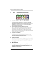
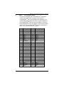
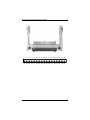
MANO110 Series AMD64 Athlon X2/Turion X2/Athlon Mini ITX Board with AMDRS780E+SB710 User’s Manual Disclaimers This manual has been carefully checked and believed to contain accurate information. Axiomtek Co., Ltd. assumes no responsibility for any infringements of patents or any third party’s rights, and any liability arising from such use. Axiomtek does not warrant or assume any legal liability or responsibility for the accuracy, completeness or usefulness of any information in this document. Axiomtek does not make any commitment to update the information in this manual. Axiomtek reserves the right to change or revise this document and/or product at any time without notice. No part of this document may be reproduced, stored in a retrieval system, or transmitted, in any form or by any means, electronic, mechanical, photocopying, recording, or otherwise, without the prior written permission of Axiomtek Co., Ltd. Caution If you replace wrong batteries, it causes the danger of explosion. It is recommended by the manufacturer that you follow the manufacturer’s instructions to only replace the same or equivalent type of battery, and dispose of used ones. Copyright 2010 Axiomek Co., Ltd. All Rights Reserved JULY 2010, Version A1 Printed in Taiwan ii ESD Precautions Computer boards have integrated circuits sensitive to static electricity. To prevent chipsets from electrostatic discharge damage, please take care of the following jobs with precautions: Do not remove boards or integrated circuits from their anti-static packaging until you are ready to install them. Before holding the board or integrated circuit, touch an unpainted portion of the system unit chassis for a few seconds. It discharges static electricity from your body. Wear a wrist-grounding strap, available from most electronic component stores, when handling boards and components. Trademarks Acknowledgments Axiomtek is a trademark of Axiomtek Co., Ltd. ® Windows is a trademark of Microsoft Corporation. ® AMI is a registered trademark of American Megatrends Inc. IBM, PC/AT, PS/2, VGA are trademarks of International Business Machines Corporation. TM Athlon is a trademark of AMD, Inc Other brand names and trademarks are the properties and registered brands of their respective owners. iii Table of Contents Disclaimers ............................................................................................ ii ESD Precautions .................................................................................. iii CHAPTER 1 ............................................................................................ 1 INTRODUCTION ..................................................................................... 1 1.1 Specifications .................................................................... 2 1.2 Utilities Supported ............................................................. 4 CHAPTER 2 ............................................................................................ 5 JUMPERS AND CONNECTORS ............................................................ 5 2.1 Board Dimensions and Fixing Holes ............................... 5 2.2 Board Layout ...................................................................... 8 2.3 Jumper Settings ............................................................... 10 2.3.1 COM1 ~ COM4 Mode Selection Jumpers (JP1, JP4, JP2, JP3) ......................................................................................... 11 2.3.2 CF Mode Setting Jumpers (JP5) ............................... 13 2.3.3 CF Power Setting Jumpers (JP5) ............................. 13 2.3.4 CMOS Clear Jumpers (JP6) ..................................... 14 2.4 Connectors ....................................................................... 15 2.4.1 PS/2 Keyboard and Mouse Connector (CN1) ........... 16 2.4.2 VGA+DVI Connector (CN2) ...................................... 16 2.4.3 HDMI Connector (CN3) ............................................. 18 2.4.4 COM1 Connector (CN4) ........................................... 18 2.4.5 USBx2 + LAN Connectors (CN5, CN6) ..................... 19 2.4.6 Audio Phone Jack Connector (CN7) ......................... 20 2.4.7 Speaker Output Connector (CN10) ........................... 20 2.4.8 ATX 12V Power Connector (CN13) .......................... 20 2.4.9 CPU Fan Connector (CN14) ..................................... 21 2.4.10 SATA Connectors (CN15, CN16) .......................... 21 2.4.11 System Fan Connector (CN17) ............................... 21 2.4.12 USB Port5 ~ Port8 Connectors (CN19, CN20) .... 22 2.4.13 COM2, COM3 and COM4 Connectors (CN30,CN24,CN25,) ........................................................................ 23 2.4.14 SMBUS Connector (CN26) ..................................... 23 2.4.15 Mini PCIe slot (CN27) ............................................ 24 2.4.16 ATX Power Connector (CN28) ................................ 26 2.4.17 DIO Connector (CN29) ........................................... 27 2.4.18 Flat Panel Bezel Connector (CN31) ........................ 28 2.4.19 CF Connector (CN32) ............................................. 29 CHAPTER 3 .......................................................................................... 31 HARDWARE DESCRIPTION ................................................................ 31 3.1 Microprocessors .............................................................. 31 3.2 BIOS .................................................................................. 31 3.3 System Memory................................................................ 31 iv 3.4 I/O Port Address Map ............................................................... 32 3.5 Interrupt Controller .......................................................... 33 CHAPTER 4 .......................................................................................... 34 AMI BIOS SETUP UTILITY................................................................... 34 4.1 Starting ............................................................................. 34 4.2 Navigation Keys ............................................................... 34 4.3 Main Menu ........................................................................ 36 4.4 Advanced Menu ............................................................... 37 CPU Configuration ............................................................. 38 Advanced Chipset Settings ................................................ 39 Onboard Device Configuration........................................... 41 PCI/PnP Settings ............................................................... 44 4.5 Power ACPI Settings ....................................................... 46 Power Management ........................................................... 47 Hardware Health Configuration .......................................... 48 4.6 Boot Menu ........................................................................ 49 Boot Device Priority ........................................................... 50 Hard Disk Drives ................................................................ 51 Security Settings ................................................................ 52 Boot Settings Configuration ............................................... 53 4.7 Exit Menu .......................................................................... 54 APPENDIX A ........................................................................................ 56 WATCHDOG TIMER ............................................................................. 56 APPENDIX B ........................................................................................ 62 DIGITAL I/O .......................................................................................... 62 v MANO110 Series Mini ITX Board User’s Manual CHAPTER 1 INTRODUCTION The MANO110 is Mini ITX board with AMD Socket AM2/AM2+, TM TM TM support AMD Athlon X2/Turion X2/Athlon Processors. It TM integrates AMD RS780E with ATI Radeon HD3200 Graphics and SB710 that deliver outstanding system performance through highbandwidth interfaces, multiple I/O functions for interactive applications and various embedded computing solutions. There are two 200-pin unbuffered DDR2 SO-DIMM sockets with maximum memory capacity up to 4GB. It also features Dual Giga-bit Ethernet, two SATA2 for Serial ATA hard drives at maximum transfer rate up to 300MB/sec, eight USB 2.0 high speed compliant, built-in high definition audio codec that can achieve the best stability and reliability for industrial applications. It provides one PCI Express x 16 slot(8 lanes) which can support AMD Hybrid CrossFire technology. . Additionally, it provides you with unique embedded features, such as 4 serial ports (COM ports) and Mini ITX form factor that applies an extensive array of PC peripherals. 1 Introduction MANO110 Series Mini ITX Board User’s Manual 1.1 Specifications CPU TM AMD Athlon System Chipset AMD RS780E & SB710 CPU Socket Socket AM2/AM2+ BIOS TM X2/Turion TM X2/Athlon Processors AMI BIOS with Axiomtek standard features System Memory Two x 200-pin unbuffered DDR2 SO-DIMM sockets Maximum to 4GB memory capacity Onboard Multi I/O Controller: Fintek F71863/F81216 Four Serial Ports (RS-232 ports) USB Interface Eight USB ports with fuse protection and complies with USB Spec. Rev. 2.0 Graphics TM ATI Radeon HD3200 Graphics: one HDMI, one DVI-D and one VGA outputs. Display mode: (1)HDMI + DVI-D (2)HDMI + VGA (3) VGA + DVI-D When connecting HDMI + DVI-D + VGA at the same time, the default dual view displays will be HDMI + DVI-D. Watchdog Timer 1~255 seconds; 255 levels Expansion Interface One PCI Express x 16 slot(8 lanes) Introduction 2 MANO110 Series Mini ITX Board User’s Manual Ethernet Two RTL8111D Giga-bit Ethernet controllers via PCIe x1 Audio HD Audio compliant (with MIC-in/Line-in/line-out & Speaker) via ALC888 Amplifier: TPA3005D2 Stereo 6 Watt Power Management ACPI (Advanced Configuration and Power Interface) Form Factor Mini ITX form factor NOTE All specifications and images are subject to change without notice. 3 Introduction MANO110 Series Mini ITX Board User’s Manual 1.2 Utilities Supported Chipset Driver LAN Driver High Definition Audio Codecs Driver HDMI Audio Codecs Driver Note: Under Microsoft Windows XP operating systems the AMD Chipset Driver requires Microsoft .NET Framework prior to installation. The AMD Chipset Driver is an application that allows you to control the configuration of your AMD product. You can verify that you have the .NET Framework by checking in the Add/Remove Programs list in the Control Panel. If the .NET Framework is not listed, please download, and install before proceeding. For more information, please visit Microsoft .NET Framework. Introduction 4 MANO110 Series Mini ITX Board User’s Manual CHAPTER 2 JUMPERS AND CONNECTORS 2.1 Board Dimensions and Fixing Holes Component Side 5 Jumpers and Connectors MANO110 Series Mini ITX Board User’s Manual Solder Side Jumpers and Connectors 6 MANO110 Series Mini ITX Board User’s Manual Rear I/O 7 Jumpers and Connectors MANO110 Series Mini ITX Board User’s Manual 2.2 Board Layout Component Side Jumpers and Connectors 8 MANO110 Series Mini ITX Board User’s Manual Solder Side 9 Jumpers and Connectors MANO110 Series Mini ITX Board User’s Manual 2.3 Jumper Settings Proper jumper settings configure the MANO110 to meet your application purpose. We are herewith listing a summary table of all jumpers and default settings for onboard devices, respectively. Jumper JP1 JP2 JP3 JP4 Default Setting COM1 Mode Selection COM3 Mode Selection COM4 Mode Selection COM2 Mode Selection Jumper Setting CN4 Pin 1: DCD Short 3-5 CN4 Pin 9: RI Short 4-6 CN24 Pin 1: DCD Short 3-5 CN24Pin 8: RI Short 4-6 CN25 Pin 1: DCD Short 3-5 CN25 Pin 8: RI Short 4-6 CN30 Pin 1: DCD Short 3-5 CN30 Pin 9: RI Short 4-6 CF Mode Select : Slave Short 1-3 CF Power Select: 5V Short 2-4 Clear CMOS Setting : Normal Short 2-4 JP5 JP6 Jumpers and Connectors 10 MANO110 Series Mini ITX Board User’s Manual 2.3.1 COM1 ~ COM4 Mode Selection Jumpers (JP1, JP4, JP2, JP3) Description COM1 (JP1) Function Jumper Setting Pin 1=5V *Pin 1=DCD (Default) Pin 9=12V *Pin 9=RI (Default) COM2 (JP4) Pin 1=5V *Pin 1=DCD (Default) Pin 9=12V *Pin 9=RI (Default) 11 Jumpers and Connectors MANO110 Series Mini ITX Board User’s Manual Description COM3 (JP2) Function Jumper Setting Pin 1=5V *Pin 1=DCD (Default) Pin 8=12V *Pin 8=RI (Default) Jumpers and Connectors 12 MANO110 Series Mini ITX Board User’s Manual 2.3.2 CF Mode Setting Jumpers (JP5) Description CF Mode Select Function Jumper Setting Slave(Default) Master 2.3.3 CF Power Setting Jumpers (JP5) Description CF Power Select Function Jumper Setting +5V(Default) +3.3V 13 Jumpers and Connectors MANO110 Series Mini ITX Board User’s Manual 2.3.4 CMOS Clear Jumpers (JP6) You may need to use this jumper is to clear the CMOS memory if incorrect settings in the Setup Utility. Description CMOS Clear Function Jumper Setting Normal (Default) Clear CMOS Jumpers and Connectors 14 MANO110 Series Mini ITX Board User’s Manual 2.4 Connectors Description PS/2 Keyboard and Mouse Connector DVI and VGA Connector HDMI Connector COM1 Connector LAN1, USB Port1 and USB Port2 Connector LAN2, USB Port2 and USB Port4 Connector Audio Connector Reserved. Reserved Speaker Output Connector Reserved PCIex16 slot, Support up to PCIex8 ATX12V Power Connector CPU FAN Connector SATA Port1 Connector SATA Port2 Connector System FAN Connector Reserved USB Port5 and USB Port6 Connector USB Port7 and USB Port8 Connector Reserved DDRII SO-DIMM Solt1 DDRII SO-DIMM Slot2 COM3 Connector COM4 Connector SMBus Connector Mini PCIe slot ATX Power Connector DIO Connector COM2 Connector Front Panel Connector CF Connector 15 Connector CN1 CN2 CN3 CN4 CN5 CN6 CN7 CN8 CN9 CN10 CN11 CN12 CN13 CN14 CN15 CN16 CN17 CN18 CN19 CN20 CN21 CN22 CN23 CN24 CN25 CN26 CN27 CN28 CN29 CN30 CN31 CN32 Jumpers and Connectors MANO110 Series Mini ITX Board User’s Manual 2.4.1 PS/2 Keyboard and Mouse Connector (CN1) The board supports one PS/2 keyboard and Mouse interface. Pin Signal Pin Signal 1 K/B Data 7 M/S Data 2 NC 8 NC 3 GND 9 GND 4 VCC 10 VCC 5 K/B CLK 11 M/S CLK 6 NC 12 NC 2.4.2 VGA+DVI Connector (CN2) CN2 is a double deck VGA & DVI connector. CN2A is a standard 15-pin DB15 connector commonly used for the CRT VGA display. CN2B is a DVI connector for the digital visual interface display. Pin Signal Pin Signal Pin Signal 1 Red 2 Green 3 Blue 4 N/A 5 GND 6 AGND N/A 7 AGND 8 AGND 9 10 GND 11 N/A 12 DDC DAT 13 Horizontal Sync 14 Vertical Sync 15 DDC CLK CN2A(CRT1) 5 1 10 15 Jumpers and Connectors 6 11 16 MANO110 Series Mini ITX Board User’s Manual Pin 1 3 Signal Pin Signal TX2- 2 TX2+ Ground 4 CRT_SPD_CLK 5 CRT_SPD DATA 6 DVI_SPD_CLK 7 DVI_SPD DATA 8 CRT-VSYNC 9 TX1- 10 TX1+ 11 Ground 12 NC 13 NC 14 VGAVCC 15 Ground 16 FPDETECT 17 TX0- 18 TX0+ 19 Ground 20 NC 21 NC 22 Ground 23 TXC+ 24 TXC- C1 CRT-RED C2 CRT-GREEN C3 CRT-BLUE C4 CRT-HSYNC C5 VGAGND CN2B(DVI-D+CRT2) 17 Jumpers and Connectors MANO110 Series Mini ITX Board User’s Manual 2.4.3 Pin HDMI Connector (CN3) Signal Pin Signal 1 TMDS Data2+ 2 3 TMDS Data2– 4 TMDS Data1+ 5 TMDS Data1 Shield 6 TMDS Data1– 7 TMDS Data0+ 8 TMDS Data0 Shield 9 TMDS Data0– 10 TMDS Clock+ 11 TMDS Clock Shield 12 TMDS Clock– 13 CEC 14 Reserved (N.C. on device) 15 SCL 16 SDA DDC/CEC Ground 18 +5 V Power 17 19 Hot Plug Detect TMDS Data2 Shield 20 HDMI Connector (CN3) 2.4.4 COM1 Connector (CN4) Pin Signal 1 DCD, Data carrier detect 2 RXD, Receive data 3 TXD, Transmit data 4 DTR, Data terminal ready 5 GND, ground 6 DSR, Data set ready 7 RTS, Request to send 8 CTS, Clear to send 9 RI, Ring indicator Jumpers and Connectors COM1(CN4) 18 MANO110 Series Mini ITX Board User’s Manual 2.4.5 USBx2 + LAN Connectors (CN5, CN6) The board supports two three-layer USB & LAN connectors, CN5 and CN6. The upper CN5B and CN6B ports are for LAN. The board is equipped with a high performance Plug and Play Ethernet interface fully compliant with the IEEE 802.3 standard. To connect the board to 10-Base-T, 100-Base-T or 1000 Base-T hub, just plug one end of cable to the Ethernet connector and connect the other end (phone jack) to a 10-Base-T, 100-Base-T or 1000 Base-T hub. The lower double-deck CN5A and CN6A are USB 2.0 ports compliant (480Mbps) that can be connected to any USB peripherals, such as keyboard, mouse, and scanner. Pin Signal 1 LAN1_MDI0+ 2 LAN1_MDI0- 3 LAN1_MDI1+ 4 LAN1_MDI1- 5 LAN1_MDI2+ 6 LAN1_MDI2- 7 LAN1_MDI3+ 8 LAN1_MDI3- A 100 LAN LED(Green)/ 1000 LAN LED(Orange) B Active LED Pin Signal 1, 5 USB Vcc 2, 6 USB - 3, 7 USB + 4, 8 USB GND 19 CN5B , CN6B CN5A , CN6A 5 6 7 8 1 2 3 4 Jumpers and Connectors MANO110 Series Mini ITX Board User’s Manual 2.4.6 Audio Phone Jack Connector (CN7) 2.4.7 Speaker Output Connector (CN10) 1 negative output for left channel 2 positive output for left channel 3 negative output for right channel 4 positive output for right channel 2.4.8 ATX 12V Power Connector (CN13) Connect the power cable to ATX1 for +12V ATX power supply. Pin Signal 1 GND 2 GND 3 +12V 4 +12V Jumpers and Connectors 20 MANO110 Series Mini ITX Board User’s Manual 2.4.9 CPU Fan Connector (CN14) FAN1 is a CPU fan connector. The fan connector on MANO110 provides power to the fan. 2.4.10 SATA Connectors (CN15, CN16) These SATA connectors are for high-speed SATA interface ports and they can be connected to hard disk devices. Pin Signal 1 2 GND SATA_TX+ 3 4 SATA_TXGND 5 SATA_RX- 6 7 SATA_RX+ GND 2.4.11 21 SATA(CN15,CN16) 1 7 System Fan Connector (CN17) Pin Signal 1 GND 2 +12V 3 Sensor CN17 Jumpers and Connectors MANO110 Series Mini ITX Board User’s Manual 2.4.12 USB Port5 ~ Port8 Connectors (CN19, CN20) These Universal Serial Bus (USB) connectors on this board are for installing versatile USB interface peripherals. These are 10-pin standard USB connectors. Pin Signal Pin Signal 1 +5V 2 +5V 3 USB- 4 USB- 5 USB+ 6 USB+ 7 Ground (GND) 8 Ground (GND) 9 Key 10 Ground (GND) Jumpers and Connectors USB(CN19,CN20) 22 MANO110 Series Mini ITX Board User’s Manual 2.4.13 COM2, COM3 and COM4 Connectors (CN30,CN24,CN25,) Please refer to the RS-232 pin assignment as listed below: Pin Signal Pin Signal 1 Data Carrier Detect (DCD) 2 Data Set Ready (DSR) 3 Receive Data (RXD) 4 Request to Send (RTS) 5 Transmit Data (TXD) 6 Clear to Send (CTS) 7 Data Terminal Ready (DTR) 8 Ring Indicator (RI) 9 Ground (GND) 10 Key 2.4.14 COM2/3/4 SMBUS Connector (CN26) Connector SMBUS1 is for SMBUS interface support. Pin 23 Signal 1 CLOCK 2 DATA 3 GND SMBUS(CN26) Hardwarre Description MANO110 Series Mini ITX Board User’s Manual 2.4.15 Mini PCIe slot (CN27) CN27 is a PCI Express Mini Card connector with support for a PCI Express x1 link and a USB 2.0 link. A PCI Express Mini Card can be applied to either PCI Express or USB 2.0. The USB 2.0 support will be helpful during the transition to PCI Express, because peripheral vendors will need time to design their chipsets to have the PCI Express function. During the transition, PCI Express Mini Cards can be quickly implemented by using USB 2.0. Pin Signal Pin Signal 1 W AKE# 2 +3.3V 3 N.C 4 GND 5 N.C 6 +1.5V 7 GND 8 N.C 9 GND 10 N.C 11 CLK- 12 N.C 13 CLK+ 14 N.C 15 GND 16 N.C 17 N.C 18 GND 19 N.C 20 N.C 21 GND 22 PERST# 23 PERN3 24 +3.3VSB 25 PERP3 26 GND 27 GND 28 +1.5V 29 GND 30 SMB_CLK 31 PETN3 32 SMB_DATA 33 PETP3 34 GND 35 GND 36 USB_D7- 37 N.C 38 USB_D7+ 39 N.C 40 GND 41 N.C 42 N.C 43 N.C 44 N.C Hardwarre Description 24 MANO110 Series Mini ITX Board User’s Manual Pin 25 Signal Pin Signal 45 N.C 46 N.C 47 N.C 48 +1.5V 49 N.C 50 GND 51 N.C 52 CN27 +3.3V Hardwarre Description MANO110 Series Mini ITX Board User’s Manual 2.4.16 ATX Power Connector (CN28) Steady and sufficient power can be supplied to all components on the board through the power connector. Please make sure all components and devices are properly installed before connecting the power connector. If you use a 20-pin ATX power supply, please remove the small cover from the power connector before plugging in the power cord; otherwise, please do not remove it. Pin Signal Pin Signal 1 3.3V 2 3.3V 3 GND 4 5V 5 GND 6 5V 7 GND 8 PW_OK 9 5V_SB 10 12V 11 3.3V 12 -12V 13 GND 14 PS_ON 15 GND 16 GND 17 GND 18 -5V 19 5V 20 5V CN28 2 0 1 0 Hardwarre Description 1 1 1 1 9 8 7 6 9 8 7 6 1 1 1 1 11 5 4 3 2 5 4 3 2 1 26 MANO110 Series Mini ITX Board User’s Manual 2.4.17 DIO Connector (CN29) The board is equipped an 8-channel digital I/O connector CN29 that meets requirements for a system customary automation control. The digital I/O can be configured to control cash drawers, sense warning signals from an Uninterrupted Power System (UPS), or perform store security control. The digital I/O is controlled via software programming. Pin 27 Signal Pin Signal 1 DIO0 2 DIO4 3 DIO1 4 DIO5 5 DIO2 6 DIO6 7 DIO3 8 DIO7 9 GND 10 +5V DIO(CN29) Hardwarre Description MANO110 Series Mini ITX Board User’s Manual 2.4.18 Flat Panel Bezel Connector (CN31) Power LED This 3-pin connector named as Pin 1, 3 and Pin 5 connect the system power LED indicator to such a switch on the case. Pin 1 is assigned as +, and Pin 3, Pin 5 as -. The Power LED lights up when the system is powered ON. External Speaker and Internal Buzzer Connector Pin 2, 4, 6 and 8 can be connected to the case-mounted speaker unit or internal buzzer. While connecting the CPU card to an internal buzzer, please short pins 2-4; while connecting to an external speaker, you need to set pins 2-4 to Open and connect the speaker cable to pin 8 (+) and pin 6 (-). ATX Power On/Off Button This 2-pin connector named as Pin 9 and 10 connect the front panel’s ATX power button to the CPU card, which allows users to control ATX power supply to be power on/off. System Reset Switch Pin 11 and 12 can be connected to the case-mounted reset switch that reboots your computer, not turns OFF the power switch. It is a better way to reboot your system for a longer life of the system’s power supply. HDD Activity LED This connection is linked to hard drive activity LED on the control panel. LED flashes when HDD is being accessed. Pin 13 and 14 connect the hard disk drive to the front panel HDD LED, Pin 13 assigned as -, and Pin 14 as +. Hardwarre Description 28 MANO110 Series Mini ITX Board User’s Manual 2.4.19 CF Connector (CN32) TM The board is equipped with a CompactFlash disk type-II socket on the solder side to support an IDE interface TM CompactFlash disk card with DMA mode supported. The socket is especially designed to avoid incorrect installation of TM the CompactFlash disk card. When installing or removing TM the CompactFlash disk card, please make sure the system TM power is off. The CompactFlash disk card is defaulted as the C: or D: disk drive in your PC system. Pin 29 Signal Pin Signal 1 GND 26 CD1- 2 Data 3 27 Data 11 3 Data 4 28 Data 12 4 Data 5 29 Data 13 5 Data 6 30 Data 14 6 Data 7 31 Data 15 7 CS0# 32 CS1# 8 Address 10 33 VS1# 9 ATASEL 34 IORD# 10 Address 9 35 IOWR# 11 Address 8 36 WE# 12 Address 7 37 INTR 13 VCC 38 VCC 14 Address 6 39 CSEL# 15 Address 5 40 VS2# 16 Address 4 41 RESET# 17 Address 3 42 IORDY# 18 Address 2 43 DMAREQ 19 Address 1 44 DMAACK- 20 Address 0 45 DASP# 21 Data 0 46 PDIAG# 22 Data 1 47 Data 8 23 Data 2 48 Data 9 24 IOCS16# 49 Data 10 25 CD2# 50 GND Hardwarre Description MANO110 Series Mini ITX Board User’s Manual 1 2 3 4 5 6 7 8 9 10 11 12 13 14 15 16 17 18 19 20 21 22 23 24 25 26 27 28 29 30 31 32 33 34 35 36 37 38 39 40 41 42 43 44 45 46 47 48 49 50 Hardwarre Description 30 MANO110 Series Mini ITX Board User’s Manual CHAPTER 3 HARDWARE DESCRIPTION 3.1 Microprocessors TM TM The MANO110 Series supports AMD Athlon X2/Turion TM , X2/Athlon Processors which make your system operated under W indows7 and Linux environments. The system performance depends on the microprocessor. Make sure all correct settings are arranged for your installed microprocessor to prevent the CPU from damages. 3.2 BIOS The MANO110 Series uses American Megatrends BIOS with 8Mbit SPI Flash, DMI, Plug and Play. 3.3 System Memory The MANO110 Series industrial CPU card supports two 200-pin unbuffered DDR2 SO-DIMM sockets for a maximum memory of 4GB DDR2 SDRAMs. The memory module can come in sizes of 64MB, 128MB, 256MB, 512MB, 1GB and 2GB. 31 Hardwarre Description MANO110 Series Mini ITX Board User’s Manual 3.4 I/O Port Address Map There are total 1KB port addresses available for assignment to other devices via I/O expansion cards . Address Devices 000-01F DMA controller #1 020-02D 024-025 028-029 02C-02D Interrupt controller #1 02E-02F Forwarded to LPC(LPC Super I/O 2) 030-031 034-035 038-039 03C-03D Interrupt controller #2 040-043 050-053 Timer/Counter (8254) 04E-04F Forwarded to LPC(LPC Super I/O 1) 060-06F Forwarded to LPC(Microcontroller for Keyboard Controller) 070-077 Real time clock, NMI 080-091 DMA page register 092 Processor I/F(Reset Generator) 093-09F DMA page register 0A0-0BF Interrupt controller #2 0C0-0DF DMA controller #2 0F0 Processor I/F 0F8-0FF Math processor 170-177 Forward to CF(IDE) Controler) 1F0-1F7 Forward to SATA Controler) 300-31F Prototype card 378-37F Parallel Port (LPT) 380-38F SDLC #2 3A0-3AF SDLC #1 3B0-3BF MDA video card 3C0-3CF EGA card Hardwarre Description 32 MANO110 Series Mini ITX Board User’s Manual Address 3.5 Devices 3D0-3DF CGA card 3F8-3FF Serial port #1 (COM1) 3E8-3EF Serial port #3 (COM3) 2F8-2FF Serial port #2 (COM2) 2E8-2EF Serial port #4 (COM4) Interrupt Controller The MANO110 Series is a 100% PC compatible control board. It consists of 16 interrupt request lin es, and four out of them can be programmable. The mapping list of the 16 interrupt request lines is shown as the following table. IRQ 33 Parity check error IRQ0 System timer output IRQ1 Keyboard IRQ2 Interrupt rerouting from IRQ8 through IRQ15 IRQ3 Serial port #2 IRQ4 Serial port #1 IRQ5 PCI Device Share IRQ7 Parallel port #1 IRQ8 Real time clock IRQ9 ACPI Controller IRQ10 Serial port #3 IRQ11 Serial port #4 IRQ12 PS/2 Mouse IRQ13 Math coprocessor IRQ14 Primary IDE channel IRQ15 SATA channe Hardwarre Description MANO110 Series Mini ITX Board User’s Manual CHAPTER 4 AMI BIOS SETUP UTILITY This chapter provides users with detailed description how to set up basic system configuration through the AMIBIOS8 BIOS setup utility. 4.1 Starting To enter the setup screens, follow the steps below: 1. 2. 4.2 Turn on the computer and press the <Del> key immediately. After you press the <Delete> key, the main BIOS setup menu displays. You can access the other setup screens from the main BIOS setup menu, such as the Chipset and Power menus. Navigation Keys The BIOS setup/utility uses a key-based navigation system called hot keys. Most of the BIOS setup utility hot keys can be used at any time during the setup navigation process. These keys include <F1>, <F10>, <Enter>, <ESC>, <Arrow> keys, and so on. Note Some of navigation keys differ from one screen to another. Left/Right The Left and Right <Arrow> keys allow you to select a setup screen. Up/Down The Up and Down <Arrow> keys allow you to select a setup screen or sub-screen. + Plus/Minus The Plus and Minus <Arrow> keys allow you to change the field value of a particular setup item. Tab The <Tab> key allows you to select setup fields. F1 The <F1> key allows you to display the General Help screen. F10 The <F10> key allows you to save any changes you have made and exit Setup. Press the <F10> key to save your changes. AMI BIOS Setup Utility 34 MANO110 Series Mini ITX Board User’s Manual 35 Esc The <Esc> key allows you to discard any changes you have made and exit the Setup. Press the <Esc> key to exit the setup without saving your changes. Enter The <Enter> key allows you to display or change the setup option listed for a particular setup item. The <Enter> key can also allow you to display the setup sub- screens. AMI BIOS Setup Utility MANO110 Series Mini ITX Board User’s Manual 4.3 Main Menu When you first enter the Setup Utility, you will enter the Main setup screen. You can always return to the Main setup screen by selecting the Main tab. There are two Main Setup options. They are described in this section. The Main BIOS Setup screen is shown below. System Time/Date Use this option to change the system time and date. Highlight System Time or System Date using the <Arrow> keys. Enter new values through the keyboard. Press the <Tab> key or the <Arrow> keys to move between fields. The date must be entered in MM/DD/YY format. The time is entered in HH:MM:SS format. CF (IDE) Master/Slave Select one of the hard disk drives to configure CF (IDE) devices installed in the system by pressing <Enter> for more options . SATA1/SATA2 Select one of the hard disk drives to configure SATA devices installed in the system by pressing <Enter> for more options . System Information Display system information. installed in the system by pressing <Enter> for more information . AMI BIOS Setup Utility 36 MANO110 Series Mini ITX Board User’s Manual 4.4 Advanced Menu The Advanced menu allows users to set configuration of the CPU and other system devices. You can select any of the items in the left frame of the screen to go to the sub menus: CPU Configuration Chipset Onboard Device Configuration USBConfiguration PCIPnP For items marked with “”, please press <Enter> for more options. 37 AMI BIOS Setup Utility MANO110 Series Mini ITX Board User’s Manual CPU Configuration This screen shows the CPU Configuration. AMI BIOS Setup Utility 38 MANO110 Series Mini ITX Board User’s Manual Advanced Chipset Settings 39 AMI BIOS Setup Utility MANO110 Series Mini ITX Board User’s Manual Primary Video Controller. IGFX-GFX0-GPP-PCI: Display from onboard VGA first. GFX0-GPPIGFX-PCI: Display from external PCIe VGA card first. UMA Frame Buffer Size. Frame buffer size is the total amount of system memory allocated solely for the onboard graphics controller. MS-DOS, for example, will use only this memory for display. Options are: Auto (default), 128MB, 256MB, 512MB. FB Location. The optional settings are: Below 4G; Above 4G. FB Location AMI BIOS Setup Utility 40 MANO110 Series Mini ITX Board User’s Manual Onboard Device Configuration Onboard LAN Boot. Use these items to enable or disable the Boot ROM function of the onboard LAN chip when the system boots up. HD Audio Azalia Device. Use these items to enable or disable the audio function of the onboard audio chip when the system boots up. Serial Port1 Address This item specifies the base I/O port address and Interrupt Request address of serial port 1. The Optimal setting is 3F8/IRQ4. Serial Port2 Address This item specifies the base I/O port address and Interrupt Request address of serial port 2. The Optimal setting is 2F8/IRQ3. Serial Port3 Address This item specifies the base I/O port address . Request address of serial port 3. The Optimal setting is 3E8 41 AMI BIOS Setup Utility MANO110 Series Mini ITX Board User’s Manual Serial Port3 IRQ This item specifies the IRQ used by the serial port 3. Serial Port4 Address This item specifies the base I/O port address . Request address of serial port 4. The Optimal setting is 2E8. Serial Port4 IRQ This item specifies the IRQ used by the serial port 4. AMI BIOS Setup Utility 42 MANO110 Series Mini ITX Board User’s Manual USB Configuration You can select options for the USB Configuration, and change the value of the selected option. A description of the selected item appears on the right side of the screen. Legacyu USB Support Use this item to enable or disable support for USB device on legacy operating system. The default setting is Enabled. USB 2.0 Controller Mode Use this item to configure the USB 2.0 controller. The default setting is FullSpeed. BIOS EHCI Hand-Off Enabling this item provide the support for operating systems without an EHCI hand-off feature. The default setting is Enabled. Legacy USB 1.1 HC Support Use this item to enable or disable support for USB 1.1 device. The default setting is Enabled. 43 AMI BIOS Setup Utility MANO110 Series Mini ITX Board User’s Manual PCI/PnP Settings AMI BIOS Setup Utility 44 MANO110 Series Mini ITX Board User’s Manual Clear NVRAM Use this item to clear the data in the NVRAM (CMOS). Here are the options for your selection, No and Yes. Plug & Play O/S When the setting is No, Use this item to configure all the devices in the system. When the setting is Yes and if you install a Plug and Play operating system, the operating system configures the Plug and Play devices not required for boot. The default setting is No. IRQ3/4/5/7/9/10/11/14/15 These items will allow you to assign each system interrupt a type, depending on the type of device using the interrupt. The option “Available” means the IRQ is going to assign automatically. Here are the options for your selection, Available and Reserved. DMA Channel 0/1/3/5/6/7 These items will allow you to assign each DMA channel a type, depending on the type of device using the channel. The option “Available” means the channel is going to assign automatically. Here are the options for your selection, Available and Reserved. Reserved Memory Size This item allows BIOS to reserve certain memory size for speci fic PCI device. 45 AMI BIOS Setup Utility MANO110 Series Mini ITX Board User’s Manual 4.5 Power ACPI Settings Suspend mode Use this item to select the ACPI state used for System Suspend. The optional settings are: S1 (POS); S3 (STR). Repost Video on S3 Resume This feature allows you to repost video on S3 resume. ACPI Version Features Set this value to allow or prevent the system to be complaint with the ACPI version. ACPI APIC support When set to disable, the system disable the Advanced Configuration and Power Interface (ACPI) support in the Advanced Programmable Interrupt Controller (APIC). When set to enable, the ACPI APIC table pointer is included in the RSDT pointer list. AMI BIOS Setup Utility 46 MANO110 Series Mini ITX Board User’s Manual Power Management Power Button Mode This option specifies how the externally mounted power button on the front of the computer chassis is used. The default setting is On/Off Keyboard PowerOn Keyboard set to support power on function. Mouse PowerOn Mouse set to support power on function. Restore on AC Power Loss This item can control how the PC will behave once power is restored following a power outage, or other unexpected shutdown. Resume On Ring This item enables or disables the function of Resume On Ring that resumes the system through incoming calls. RTC Resume You can set “Resume On RTC Alarm” item to enabled and key in Data/time to power on system. 47 AMI BIOS Setup Utility MANO110 Series Mini ITX Board User’s Manual Hardware Health Configuration Cuban Mode Setting (Smart Fan) When set to disable, the CPU FAN are always on. Temperature 1 Limit of Highest Set the temperature limit for CPU FAN high speed. Temperature 1 Limit of Lowest Set the temperature limit to for CPU FAN low speed. AMI BIOS Setup Utility 48 MANO110 Series Mini ITX Board User’s Manual 4.6 Boot Menu The Boot menu allows users to change boot options of the system. You can select any of the items in the left frame of the screen to go to the sub menus: Boot Device Priority Hard Disk Drives Security Boot Settings Configuration For items marked with “”, please press <Enter> for more options. 49 AMI BIOS Setup Utility MANO110 Series Mini ITX Board User’s Manual Boot Device Priority The Boot Device Priority screen specifies the order in which the system checks for the device to boot from the available devices. AMI BIOS Setup Utility 50 MANO110 Series Mini ITX Board User’s Manual Hard Disk Drives Use this screen to view the hard disk drives in the system. 51 AMI BIOS Setup Utility MANO110 Series Mini ITX Board User’s Manual Security Settings Change Supervisor Password Select this option and press <Enter> to access the sub menu. You can use the sub menu to change the supervisor password. AMI BIOS Setup Utility 52 MANO110 Series Mini ITX Board User’s Manual Boot Settings Configuration Quick Boot Enabling this item lets the BIOS skip some power on self tests (POST).The default setting is Enabled. AddOn ROM Display Mode This item selects the display mode for option ROM. The default setting is Force BIOS. Boot Num-Lock Use this item to select the power-on state for the NumLock. The default setting is On. Wait For ‘F1’ If Error If this item is enabled, the system waits for the F1 key to be pressed when error occurs. The default setting is Enabled. 53 AMI BIOS Setup Utility MANO110 Series Mini ITX Board User’s Manual 4.7 Exit Menu The Exit menu allows users to load your system configuration with optimal or failsafe default values. Save Changes and Exit When you have completed the system configuration changes, select this option to leave Setup and reboot the computer so the new system configuration parameters can take effect. Select Save Changes and Exit from the Exit menu and press <Enter>. Select Ok to save changes and exit. Discard Changes and Exit Select this option to quit Setup without making any permanent changes to the system configuration. Select Discard Changes and Exit from the Exit menu and press <Enter>. Select Ok to discard changes and exit. AMI BIOS Setup Utility 54 MANO110 Series Mini ITX Board User’s Manual Discard Changes Use this item to abandon all changes. Load Optimal Defaults It automatically sets all Setup options to a complete set of default settings when you select this option. The Optimal settings are designed for maximum system performance, but may not work best for all computer applications. In particular, do not use the Optimal Setup options if your computer is experiencing system configuration problems. Select Load Optimal Defaults from the Exit menu and press <Enter>. 55 AMI BIOS Setup Utility MANO110 Series Mini ITX Board User’s Manual APPENDIX A WATCHDOG TIMER A1 Watchdog Timer After the system stops working for a while, it can be auto-reset by the Watchdog Timer. The integrated Watchdog Timer can be set up in the system reset mode by program. A1.1 Program Watchdog Timer The W atchdog timer is built in super I/O F71863. The F71863 I/O address port is 2E hex and 2F hex. 2E hex is index port. 2F hex is data port. Un-lock Super I/O Select logical device and set register Enable W atchdog Timer Function Use W atchdog Timer Function Lock Super I/O Watchdog Timer 56 MANO110 Series Mini ITX Board User’s Manual Watchdog Timer Register Index Port (2E hex) Data Port (2F hex) Description 87 hex --- Unlock Super I/O. Two successive writes of 87 hex be applied to 2E hex. 2B hex (F71863) Bit 4 Select W DTO pin function. 1: W DT Output. 0: GPIO14. 07 hex 07 hex Select register of watchdog timer 30 hex Bit 0 W rite 1 to enable watchdog timer. Disable is write 0. F0 hex Bit 7 W rite 1 to enable W DTO# output F5 hex Bit 3 W rite 0 set second as counting unit. W rite 1 is minute. F5 hex Bit 5 W rite 1 counting enable F5 hex Bit 4 W rite 1 Output mode pulse F5 hex Bit 0:1 1: 25 ms pulse width 57 Watchdog Timer MANO110 Series Mini ITX Board User’s Manual Watchdog Timer Register Index Port (2E hex) Data Port (2F hex) Description F6 hex Value 0: Stop timer. 1~FF hex: W rite non-zero value the counter to load the value to watchdog counter and start counting down. W rite new value to this register can reset timer to count with the new value. AA hex --- Lock Super I/O W rite AA hex to 2E/2F hex. Watchdog Timer 58 MANO110 Series Mini ITX Board User’s Manual A1.2 Example Program Code The sample code is for debug.exe. Sample code is index port 2E hex, data port 2F hex and time-out value 30 second. A1.2.1 Set and Start Up The W atchdog Timer Unlock Super I/O O 2E 87 O 2E 87 Set WDTO Multifunction Pin Definition O 2E 2B O 2F 10 Select Logic Device 7 O 2E 07 O 2F 07 Active Logic Device O 2E 30 O 2F 01 Enable WDT O 2E F0 O 2F 80 Set WDT Time-out Value is 30 O 2E F6 O 2F 1E Enable WDT Counting And setting Mode is: Second Mode/Output mode Pulse, Pulse width 25 O 2E F5 O 2F 31 Lock Super I/O O 2E AA 59 Watchdog Timer MANO110 Series Mini ITX Board User’s Manual A1.2.2 Reset The Watchdog Timer Unlock Super I/O O 2E 87 O 2E 87 Select Logic Device 7 O 2E 07 O 2F 07 Active Logic Device O 2E 30 O 2F 01 Set WDTO Multifunction Pin GPIO14 Definition O 2E 2B O 2F 00 Disable WDT O 2E F0 O 2F 00 Clear Status O 2E F5 O 2F 40 Back to original register value O 2E F5 O 2F 00 Set WDT Time-out Value O 2E F6 O 2F 00 Lock Super I/O O 2E AA Watchdog Timer 60 MANO110 Series Mini ITX Board User’s Manual 1.2.3 Disable The Watchdog Timer Unlock Super I/O O 2E 87 O 2E 87 Select Logic Device 8 O 2E 07 O 2F 07 Inactive Logic Device O 2E 30 O 2F 00 Lock Super I/O O 2E AA 61 Watchdog Timer MANO110 Series Mini ITX Board User’s Manual APPENDIX B DIGITAL I/O Digital I/O Software Programming Example Pin Signal Pin Signal 1 DIO0 2 DIO4 3 DIO1 4 DIO5 5 DIO2 6 DIO6 7 DIO3 8 DIO72 9 GND 10 +5V CN29 GPIO control #define SMBusBase 0x0B00 #define PCA9554SlaveAddr 0x40 #define ICH_SMBUS_HOST_STAT 0x00 #define ICH_SMBUS_HOST_CTRL 0x02 #define ICH_SMBUS_HOST_CMD 0x03 #define ICH_SMBUS_HOST_ADDR 0x04 #define ICH_SMBUS_HOST_DATA_0 0x05 #define ICH_SMBUS_HOST_DATA_1 0x06 #define ICH_SMBUS_HOST_BLK_DATA 0x07 #define ICH_SMBUS_SLVE_STAT 0x10 Digital I/O 62 MANO110 Series Mini ITX Board User’s Manual Configure GPIO pin direction as 4 inputs and 4 outputs outb(0xFF,SMBusBase + ICH_SMBUS_HOST_STAT); // Clear host status outb(PCA9554SlaveAddr, SMBusBase + ICH_SMBUS_HOST_ADDR); // Set slave address outb(0x03, SMBusBase + ICH_SMBUS_HOST_CMD); // Configuration register for PCA9554 outb(0xF0, SMBusBase + ICH_SMBUS_HOST_DATA_0); // outb(0x48, SMBusBase + ICH_SMBUS_HOST_CTRL); // Trigger SMBus Byte operation Configure GPIO output pin to high outb(0xFF,SMBusBase + ICH_SMBUS_HOST_STAT); // Clear host status outb(PCA9554SlaveAddr, SMBusBase + ICH_SMBUS_HOST_ADDR); // Set slave address outb(0x01, SMBusBase + ICH_SMBUS_HOST_CMD); // Output register for PCA9554 outb(0x0F, SMBusBase + ICH_SMBUS_HOST_DATA_0); outb(0x48, SMBusBase + ICH_SMBUS_HOST_CTRL); // Trigger SMBus Byte operation 63 Digital I/O