1
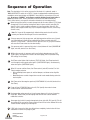
Flo-Direct® Complete Thermal Exchange Gas Fired Water Heater
Installation, Operation, and Maintenance Manual
Warning: If the information in these instructions is not followed
exactly, a fire or explosion may result causing property damage,
personal injury, or death.
• Do not store or use gasoline or other flammable vapors and liquids in the
vicinity of this or any other appliance.
• What to do if you smell gas
–– Do not try to light any appliance.
–– Do not touch any electrical switch; do not use any phone in your building.
–– Immediately call your gas supplier from a neighbor's phone. Follow the gas
supplier's instructions.
If you cannot reach your gas supplier, call the fire department.
• Installation and service must be performed by a qualified installer, service
agency, or gas supplier.
Certified to
U.S. patent 5,924,391
5
Armstrong International
221 Armstrong Blvd., Three Rivers, Michigan, 49093 - USA
Ph. (269) 279-3602 Toll Free (888) HOT-HOSE (468-4673) Fax (269) 279-3130
Keep this manual with
heater for future reference.
Armstrong
Contents
Transfer Pump
. . . . . . . . . . . . . . . . . . . . . . . . . . . . . . . . . . . . . . . . . . . . . . . . . . . . . . . . .
23
. . . . . . . . . . . . . . . . . . . . . . . . . . . . . . . . . . . . . . . . . . . . . . . . . . . . . . . . . . .
23
Storage Tank
The Flo-Direct System..............................2
Typical System
Specifications
. . . . . . . . . . . . . . . . . . . . . . . . . . . . . . . . . . . . . . . . . . . . . . 2
. . . . . . . . . . . . . . . . . . . . . . . . . . . . . . . . . . . . . . . . . . . . . . . .
4
Main Power Connection
Description of Operation
Sequence of Operation
Pre-Start-Up Checklist
4
Materials of Construction
4
. . . . . . . . . . . . . . . . . . . . . . . . . . . . . . . . . . . . . . .
Operational Specifications
4
. . . . . . . . . . . . . . . . . . . . . . . . . . . . . . . . . . . . . .
Technical Specifications
4
Dimensions
. . . . . . . . . . . . . . . . . . . . . . . . . . . . . . . . . . . . . . . . . . . . . . . . . . . . . . . .
5
. . . . . . . . . . . . . . . . . . . . . . . . . . . . . . . . . . . . . . . . . . . . . . . . . . . . . . . . . .
6
. . . . . . . . . . . . . . . . . . . . . . . . . . . . . . . . . . . . . . . . .
Orientation
. . . . . . . . . . . . . . . . . . . . . . . . . . . . . . . . . . . . . . . . . . . .
Materials of Construction
8
. . . . . . . . . . . . . . . . . . . . . . . . . . . . . . . . . . . . . . .
Dimensions and Operational Specifications
8
Orientation
8
. . . . . . . . . . . . . . . . . . . . . . . . . . . . . . . . . . . . . . . . . . . . . . . . . . . . . . . . . .
9
. . . . . . . . . . . . . . . . . . . . . . . . . . . . . . . . . . . . . . . . . . . . . . . . . . . . . . . . . . .
Materials of Construction
General Specifications
9
Orientation
10
. . . . . . . . . . . . . . . . . . . . . . . . . . . . . . . . . . . . . . . . . . . . . . . . . . . . . . . . . .
Assembly and Installation........................
Unpacking
Installing Large Heaters
Installing Small Heaters
Installing Exhaust Ducting
Installing Intake Air Ducting
Water Connections
Fuel Connection
11
. . . . . . . . . . . . . . . . . . . . . . . . . . . . . . . . . 11
. . . . . . . . . . . . . . . . . . . . . . . . . . . . . . . . .
13
. . . . . . . . . . . . . . . . . . . . . . . . . . . . . . 15
. . . . . . . . . . . . . . . . . . . . . . . . . . . .
16
. . . . . . . . . . . . . . . . . . . . . . . . . . . . . . . . . . . . . . . . .
17
. . . . . . . . . . . . . . . . . . . . . . . . . . . . . . . . . . . . . . . . . . . . .
18
Electrical Panels...................................
Control Panel
Disconnect Panel
Heater Label
Electrical Connections
19
. . . . . . . . . . . . . . . . . . . . . . . . . . . . . . . . . . . . . . . . . . . 20
. . . . . . . . . . . . . . . . . . . . . . . . . . . . . . . . . . . . . . . . . . . . . . . . . .
20
. . . . . . . . . . . . . . . . . . . . . . . . . . . . . . . . . . . .
21
Top Plate to Upper Canister
27
28
. . . . . . . . . . . . . . . . . . . . . . . . . . . . . . . . . . . .
28
. . . . . . . . . . . . . . . . . . . . . . . . . . . . . . . . 28
. . . . . . . . . . . . . . . . . . . . . . . . . . . . . . . . . . . . . . . . . . . . . .
28
30
. . . . . . . . . . . . . . . . . . . . . . . . . . . . . . . . . . . 30
. . . . . . . . . . . . . . . . . . . . . .
31
32
. . . . . . . . . . . . . . . . . . . . . . . . . . . . . . . . . . . . 32
. . . . . . . . . . . . . . . . . . . . . . . . . . . . . . . . . . . . . . . . . . . . . . . . . . . . . . . . 33
Parts Lists...........................................
34
Top Plate
Water Train
Control Box
Disconnect Box
Fuel Train
Lower Canister
Storage Tank
. . . . . . . . . . . . . . . . . . . . . . . . . . . . . . . . . . . . . . . . . . . . . . . . . . . . . . .
34
. . . . . . . . . . . . . . . . . . . . . . . . . . . . . . . . . . . . . . . . . . . . . . . . . . . .
35
. . . . . . . . . . . . . . . . . . . . . . . . . . . . . . . . . . . . . . . . . . . . . . . . . . . .
36
. . . . . . . . . . . . . . . . . . . . . . . . . . . . . . . . . . . . . . . . . . . . . . 37
. . . . . . . . . . . . . . . . . . . . . . . . . . . . . . . . . . . . . . . . . . . . . . . . . . . . . .
38
. . . . . . . . . . . . . . . . . . . . . . . . . . . . . . . . . . . . . . . . . . . . . . 39
. . . . . . . . . . . . . . . . . . . . . . . . . . . . . . . . . . . . . . . . . . . . . . . . . 40
Appendix: Modulating Burner....................
Descriptions of the major modulation
components
Operation:
19
. . . . . . . . . . . . . . . . . . . . . . . . . . . . . . . . . . . . . . . . . . . . . . . . .
. . . . . . . . . . . . . . . . . . . . . . . . . . . . . . . . . . . .
Troubleshooting Table
PLC I/Os
11
. . . . . . . . . . . . . . . . . . . . . . . . . . . . . . . . . . . . . . . . . . . . . . . . . . . . . 26
Troubleshooting....................................
9
9
. . . . . . . . . . . . . . . . . . . . . . . . . . . . . . . . . . . Maintenance Schedule
High Temperature Switch Check
. . . . . . . . . . . . . . . . . . . . . . . . . . . . . . . . . . . . . . . . . . .
. . . . . . . . . . . . . . . . . . . . . . . . . . . . . . . . . . . . . . . . .
25
Periodic Maintenance.............................
. . . . . . . . . . . . . . . . . . . . . . . . . . . . . . . . . . . . . . .
Specifications by Model
25
Inspecting Installation
Inspecting Water System
Commissioning
. . . . . . . . . . . . . . . .
24
. . . . . . . . . . . . . . . . . . . . . . . . . . . . . . . . .
Commissioning....................................
8
Transfer Pump Assembly
. . . . . . . . . . . . . . . . . . . . . . . . . . . . . . . . . . . . . . . . . . . . .
Operation...........................................
. . . . . . . . . . . . . . . . . . . . . . . . . . . . . . . . . . . . . . . . . . . . . . . . . . . . . . . . . . . . . . . . . . . .
Storage Tank
22
. . . . . . . . . . . . . . . . . . . . . . . . . . . . . . . . . . . . . . . . . . . . .
Safety..................................................1
Heater
Upper to Lower Canister
41
. . . . . . . . . . . . . . . . . . . . . . . . . . . . . . . . . . . . . . . . . . . . . . . . . . .
41
. . . . . . . . . . . . . . . . . . . . . . . . . . . . . . . . . . . . . . . . . . . . . . . . . . . . . 42
Limited Warranty and Remedy..................
44
Notes................................................
45
21
. . . . . . . . . . . . . . . . . . . . . . . . . . . . . . . . . . . . . . . . .
Armstrong International
221 Armstrong Blvd., Three Rivers, Michigan, 49093 - USA
Ph. (269) 279-3602 Toll Free (888) HOT-HOSE (468-4673) Fax (269) 279-3130
Safety
Icon Legend
If instructions are not followed:
— injury or death and property damage are imminent
— injury or death and property damage are possible
— potential property damage, expensive repairs, and/or voiding the warranty may result
Warning: If the information in these instructions is not followed
exactly, a fire or explosion may result causing property damage,
personal injury, or death.
• Do not store or use gasoline or other flammable vapors and liquids in the
vicinity of this or any other appliance.
• What to do if you smell gas
–– Do not try to light any appliance.
–– Do not touch any electrical switch; do not use any phone in your building.
–– Immediately call your gas supplier from a neighbor's phone. Follow the gas
supplier's instructions.
If you cannot reach your gas supplier, call the fire department.
• Installation and service must be performed by a qualified installer, service
agency, or gas supplier.
Note: Operating with any safety device bypassed will void the warranty.
� Applicable codes must be followed and
supersede any other instructions. Generally
applicable codes in the US include:
• NEC
• NFPA #86
� Read this manual.
� Improper installation or operation may cause a fire
or explosion resulting in property damage, personal
injury, or death. Armstrong strongly recommends that
a qualified installer be used.
� Service must be performed by a qualified person.
� Improper installation, start-up, operation, maintenance,
or service may void the warranty.
� Hot water or metal may cause scald burns. Skin
exposure to 140° water or metal for only five
seconds may cause a second degree burn.
Armstrong International
IOM-706
Flo-Direct Water Heater
� Do not attempt to use the heater if it
has been submerged in water. Contact a
qualified service technician to inspect it and
replace compromised parts.
Page 1 of 45
The Flo-Direct System
Armstrong's Flo-Direct water heaters:
� Are designed for industrial applications
� Use complete thermal exchange technology
� Come in sizes from 1 to 16 million Btu/hr
� Heat water up to 185 °F maximum
Typical System
Heater
Transfer
Pump
Storage Tank
Armstrong reserves the right to make design or
specification changes without notification.
Armstrong International
IOM-706
Flo-Direct Water Heater
Page 2 of 45
Typical System
Flo-Direct water heaters are highly efficient, low maintenance systems.
� Complete thermal exchange technology means no fuel is used for warmup or idle time and no energy is lost through conversion or exchange.
� Without internal moving parts, there is very little to maintain.
� Water conditioning is not required.
Flo-Direct systems are highly customizable at both a system
and component level. The information in this manual
generally uses a 5 million Btu/hr unit and is intended to
be typical. Illustrations are not intended to be complete or
correct in every detail. System-specific drawings, including
wiring schematics, are provided with each unit and should be
referred to when installing and operating your system.
Common options:
� Gravity drain (without a transfer pump)
� Standard (consistent incoming water temperature) or modulating
burner actuator
� Natural gas or propane fuel
� Remote or integral tank
Other available options include:
� Skid-packaged heaters
� Performance matched components
� Ultra-low NOx emissions
� Non-standard fuels
� Storage tank heating element
Peripheral components:
� Digital mixing valves
� Variable frequency drive pump
� Hose stations
Optional services:
� Turn-key installation
� Installation project management
� System assessment and optimization
� Energy conservation measures (ECM)
For further information, visit http://www.armstronginternational.com/flo-direct
or contact Armstrong.
Note: Armstrong provides separate IOMs for the burner, blower, and for optional
components. Consult the appropriate document for more information.
Armstrong International
IOM-706
Flo-Direct Water Heater
Page 3 of 45
Typical System
Specifications
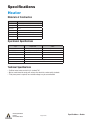
Heater
Materials of Construction
Component
Material
Canister
304 SS (10 ga. ≤ AFD-8000; 3/16 > AFD-8000)
Canister gasket
WARCO white (food grade buna rubber)
Flame tube
304 SS
Gas piping
Malleable iron with standard yellow finish
Water piping
Copper with brass or bronze fittings OR welded SS
Spray ring
304/316 SS
Pall ring
304 SS
Operational Specifications
Spec
English Units
SI Units
Gas supply pressure
2–6 psig (optimum 4–5.5 psig)
0.14–0.41 bar (optimum 0.28–0.38 bar)
Water supply pressure
30–100 psig with ± 5 psig variation
2.07–6.84 bar with ± 0.34 bar variation
Inlet water temperature
32 °F to 120 °F
0 °C to 49 °C
Outlet water temperature
185 °F
85 °C
Water temperature differential
10 °F to 140 °F
NOx emission
Thermal efficiency
5.6 °C to 77.8 °C
30–50 ppm
99.7%
Technical Specifications
• Flo-Direct water heaters are built to UL standard 795
• May be manufactured to comply with various other electrical or water quality standards
• Three-phase power is required; most available voltages may be accommodated
Armstrong International
IOM-706
Flo-Direct Water Heater
Page 4 of 45
Specifications — Heater
Dimensions
E
A
C
2
B
1
D
Connections*
1
Model
Dimensions
2
A
B
C
D
Weight
E
Btu/hr
kW
mm
in.
mm
in.
mm
lb
kg
39
991
24
610
8
203
825
375
1,000,000
292
41
1041
26
660
8
203
850
386
1,500,000
439
1930
44
1118
30
762
10¾
273
1500
680
2,000,000
585
76
1930
44
1118
36
914
12
305
1600
725
3,000,000
878
2642
80
2032
48
1214
40
1016
14
356
2000
907
4,200,000
1171
3226
97
2464
65
1651
44
1118
16
406
2500
1136
5,300,000
1464
132
3353
100
2540
70
1778
47
1194
18
457
2900
1316
6,300,000
1757
50
139
3531
107
2718
77
1956
50
1270
18
457
3200
1455
7,400,000
2050
50
139
3531
107
2718
77
1956
50
1270
18
457
3200
1455
8,400,000
2342
2
50
169
4293
139
3531
107
2718
60
1524
20
508
5000
2273
9,500,000
2635
80
2
50
181
4597
151
3835
119
3023
61
1549
20
508
5200
2405
10,500,000
2928
100
3
80
181
4597
151
3835
119
3023
61
1549
22
559
5500
2495
11,600,000
3221
100
3
80
181
4597
151
3835
119
3023
61
1549
22
559
5500
2495
12,600,000
3514
4
100
3
80
192
4877
161
4089
129
3277
70
1778
24
610
7000
3175
13,700,000
3807
4
100
3
80
192
4877
161
4089
129
3277
70
1778
24
610
7000
3175
14,700,000
4099
AFD-15000
4
100
3
80
192
4877
161
4089
129
3277
70
1778
24
610
7000
3175
15,800,000
4392
AFD-16000
4
100
3
80
216
5486
185
4699
153
3886
70
1778
24
610
7500
3402
16,000,000
4685
in.
mm
in.
mm
in.
mm
in.
mm
in.
AFD-1000
1
25
1
25
95
2413
71
1803
AFD-1500
1
25
1
25
97
2464
73
1854
AFD-2000
1-1/2
40
1-1/2
40
100
2540
76
AFD-3000
2
50
1-1/2
40
100
2540
AFD-4000
2
50
2
50
104
AFD-5000
2-1/2
65
2
50
127
AFD-6000
3
80
2
50
AFD-7000
3
80
2
AFD-8000
3
80
2
AFD-9000
3
80
AFD-10000
3
AFD-11000
4
AFD-12000
4
AFD-13000
AFD-14000
*Connections may be NPT, flanged, or use a sanitary ferrule as required.
Armstrong International
IOM-706
Flo-Direct Water Heater
Page 5 of 45
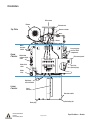
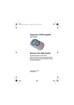
Specifications — Heater
Orientation
UV scanner
Blower
Exhaust vent
Burner actuator
Top Plate
Burner
Water
pressure
switch
Upper
Canister
See next page
for Fuel Train
components
Water flow
volume adjust
valve
Disconnect panel
Control panel
Water inlet
valve
Gas inlet
(behind pipe)
Water
inlet
High temp
shut-off switch
Lower
Canister
Level
switches
Hot water outlet
Anchoring tab
Drain plug
Armstrong International
IOM-706
Flo-Direct Water Heater
Page 6 of 45
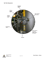
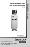
Specifications — Heater
Fuel Train Components
Regulated
pressure
display
High gas
pressure
switch
Proof of Closure
(POC) switch
Low gas
pressure
switch
Dual blocking
valves
Visual display of
valve state
(white = closed
red = open)
Regulator
Armstrong International
IOM-706
Flo-Direct Water Heater
Page 7 of 45
Specifications — Heater
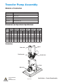
Transfer Pump Assembly
Materials of Construction
Component
Material
Piping
Type L hard copper/welded 304 OR 316 stainless steel
Braided flex hose
Stainless steel
Pump
Stainless steel (TEFC motor)
Bypass valve
Bronze (110 VAC solenoid/stainless steel motorized butterfly valve)
Globe valve
Bronze/stainless steel
Stand
Carbon steel (painted)
Dimensions and Operational Specifications
Model
TP-50
Maximum
Flow Rate
Inlet
Connection
Outlet
Connection
Flow Control
Valve
Bypass
Valve
Pump
Power
GPM
m3/hr
in.
mm
in.
mm
in.
mm
in.
mm
HP
kW
50
11.4
1-1/2
40
1-1/2
40
1
25
1
25
2
1.49
TP-90
90
20.4
1-1/2
40
2
50
1-1/2
40
1-1/2
40
3
2.24
TP-135
135
30.7
2
50
2-1/2
65
2
50
1-1/2
40
5
3.73
TP-200
200
45.4
2-1/2
65
3
80
2
50
2
50
7-1/2
5.59
TP-275
275
62.5
2-1/2
65
4
100
2-1/2
65
2
50
10
7.46
TP-350
350
79.5
3
80
4
100
3
80
2
50
10
7.46
Orientation
Bypass
Water outlet
Throttling valve
Solenoid valve
Pump
Water inlet
Armstrong International
IOM-706
Flo-Direct Water Heater
Page 8 of 45
Specifications — Transfer Pump Assembly
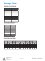
Storage Tank
Materials of Construction
Component
Material
Structural layer
Fiber-reinforced plastic
Structural and liner resin
DerakaneTM 441-400
Exterior layer resin
Isophthalic polyester
Tank finish
Gel coat with UV inhibitor
Color
Gray (AT071)
Tank fittings
Fiber-reinforced plastic
Vent
Fiber-reinforced plastic
Manhole and cover
Fiber-reinforced plastic
Manhole cover bolts
Stainless steel
Manhole gasket
EPDM
Hold down and lifting lugs
Powder-coated carbon steel
General Specifications
Design standard
ASTM D49097-00
Maximum pressure
Atmospheric
Vacuum
None
Maximum temperature
180 °F (82.2 °C)
Specific gravity
1.2
Seismic code/design
None
Wind load
0 mph/kph
Immersion heater port
2" NPT
Sight glass port
1" NPT
Insulation thickness
2" (50 mm)
Specifications by Model
Nominal Storage
Volume
Model
RST-1001
Gal
m3
1000
3.785
Piping Connections
No. Inlet
Connections
1
Inlet
Height
Outlet
Weight
(Empty)
Diameter
in.
mm
in.
mm
in.
mm
in.
mm
lb
kg
2-1/2 NPT
65
2 NPT
50
96
2442
65
1651
1200
544
RST-3001
3000
11.36
1
3 NPT
80
3 Flange
80
148
3759
87
2210
2000
907
RST-5001
5000
18.93
1
4 Flange
100
4 Flange
100
152
3861
113
2870
2600
1179
RST-5002
5000
18.93
2
4 Flange
100
4 Flange
100
152
3861
113
2870
2600
1179
Armstrong International
IOM-706
Flo-Direct Water Heater
Page 9 of 45
Specifications — Storage Tank
Orientation
Screened vent
Water inlet
Manway
Recirculation
return
Upper sight glass
mount (1" NPT)
Float switch mount
for heater stop
Float switch mount
for heater start
Thermometer
mount
Lower sight glass
mount (1" NPT)
Float switch mount
for low water to
pump cutoff (if used)
Outlet
Outlet for immersion
heater (2" NPT)
Armstrong International
IOM-706
Flo-Direct Water Heater
Page 10 of 45
Specifications — Storage Tank
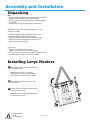
Assembly and Installation
Unpacking
Note:
• Obvious damage should be noted on delivery paperwork. Hidden
damage must be reported to carrier within ten days.
• Cleaning heater using local plant standard is recommended prior
to installation.
• Storage tanks are typically shipped directly from vendor.
Depending on heater size and mode of shipping, one of two
scenarios may apply.
Small heaters (approximately AFD-5000 and under) when
shipped with adequate height clearance in vehicle:
• Top plate and upper canister will be attached and upright.
• A fork lift will usually be adequate for moving. Use of a
strap or chain is recommended.
Large heaters:
• Top plate will be bolted to lower canister.
• Upper canister will be on its side with top covered.
• A crane or hoist of some kind will be needed for moving. At least
two, preferably four straps or chains will be needed.
Installing Large Heaters
1 Stand upper canister upright and position near
final heater location.
Note: Remove cover and, if necessary,
rearrange palls until they are approximately
level and do not interfere with spray nozzles.
2 Wipe off flange and place gasket on it with
holes aligned.
3 Remove cable ties from wiring and unbolt top
plate from lower canister.
Note: Long bolt in blower motor bracket must
be reinstalled in that hole.
Armstrong International
IOM-706
Flo-Direct Water Heater
Page 11 of 45
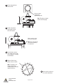
4 Remove top plate from
lower canister.
Attach as shown
to keep plate
approximately level.
Note: Top plates on largest
heaters have lifting lugs.
5 Position top plate on
top of upper canister
with holes aligned.
Orient so union in fuel
line can be connected.
Note: "Gas" and "fuel" are
used interchangeably in
this document.
6 Install all bolts and start
nuts. Liberal use of an antisieze compound is strongly
recommended.
7 Tighten all bolts using
pattern shown or similar.
1
Note: This pattern is for
heaters with 16 bolts.
24-bolt patterns should be
tightened similarly.
9
5
16
13
3
8
12
11
4
7
14
15
6
Armstrong International
IOM-706
Flo-Direct Water Heater
10
2
Page 12 of 45
8 Attach canister sections as
for a small heater below.
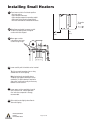
Installing Small Heaters
1 Place lower canister in final heater position:
•
•
•
•
•
On level surface
With adequate clearances
With adequate support for operating weight
With outlet facing transfer pump location
Not near flammable or combustible materials
To transfer
pump
2 Wipe flange and gasket to remove any dirt
or debris and place gasket on flange of
canister with holes aligned.
18"
(sides and
back)
3 Move upper canister
Wall
into position over lower
canister using lift lugs.
4 Lower carefully until a few bolts can be inserted.
Tip: Using several tapered pry bars or long
screwdrivers will aid in aligning.
Note: Control panels are typically above
standpipe (see approval drawing for actual
orientation). If slight indexing is required to
align outlet, some rewiring may be necessary
between canister sections.
5 Lower upper canister completely, insert all
bolts, and start nuts. Liberal application
of an anti-sieze compound is strongly
recommended.
6 Raise entire heater slightly above floor to
allow self-aligning.
Armstrong International
IOM-706
Flo-Direct Water Heater
Page 13 of 45
48"
(front)
7 Snug all bolts using pattern
shown or similar.
1
9
5
16
13
3
8
12
11
4
7
14
15
6
10
2
8 Lower onto floor and tighten all bolts
using pattern shown or similar.
Note: Leakage is normal pending
stress relief. Tighten applicable bolts as
required when leaks appear.
9 Armstrong recommends anchoring
heater in place.
10 Repeat tightening sequence after
several hours and after a few days of
operation or as leaks occur.
Armstrong International
IOM-706
Flo-Direct Water Heater
Page 14 of 45
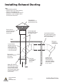
Installing Exhaust Ducting
Note:
• Roof installation preferred.
• Flo-Direct heater is not naturally drafting;
exhaust is under slight pressure.
• Insulation is not required because exhaust
temperature is only a few degrees above
incoming water temperature.
Cover external
termination with rain
guard and bird screen.
Exterior opening
must be at least equal
to cross section of
exhaust duct.
Provide independent
support for duct. Do not
rest weight on heater.
Install horizontal exhaust
duct sloping upward to drain
condensate in duct (1/4" per
foot is recommended).
Roof
Bird screen
installation is
recommended.
Connect exhaust
ducting using either
CPVC or single wall,
welded stainless steel.
Snap-together ducting
is not recommended.
Duct must be
same size or larger
than heater's
exhaust outlet.
Models AFD-1000 and
AFD-1500 require a rubber
sewer connection boot to
connect. All other models
have a flange (shown). Joint
should be sealed with RTV
(clear silicone).
Armstrong International
IOM-706
Flo-Direct Water Heater
Condensate will
drip from end of
horizontal ducting.
Install where dripping
will not be a nuisance
or ice a hazard.
Armstrong
recommends no
bend sharper
than 45°.
Wall
Heater
stack
Page 15 of 45
Installing Exhaust Ducting
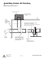
Installing Intake Air Ducting
Note:
Do not use manifold connected to other appliances.
Do not run heater under negative air pressure.
Top must be solid metal.
Typical enclosure in
sheet metal box with
screen.
Roof
Provide
independent
support for duct.
Do not rest weight
on heater.
Bird screen
required.
Using outside air is recommended, especially:
• When inside air is not dust free
• When inside air is under positive or negative pressure
Alternatively, filtration may be used.
Wall
Armstrong International
IOM-706
Flo-Direct Water Heater
Duct diameter must be at least
as large as intake diameter on
blower. 15% diameter increase
is recommended every 10 feet
removed from heater.
Page 16 of 45
Material can be:
• CPVC
• Galvanized sheet metal
• Single wall stainless steel
Installing Intake Air Ducting
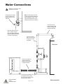
Water Connections
Warranty is void unless clean,
potable water is used.
If large pressure swings
occur, install pressure
regulating valve in inlet
water line.
Note: Incoming water must not
contain any chloride compounds
above 100 ppm or salts. These
will destroy 304 stainless steel.
(Alternative metals are available.)
Line from transfer
pump must be routed
to top of storage tank
to prevent backflow.
Inlet water pipe must be at
least as large as heater's
water inlet piping. Maximum
recommended water velocity
is 9 ft/sec in inlet piping.
Line from transfer
pipe must be at least
as large as transfer
pump pipe.
Storage tank
Suction hose between
heater and transfer
pump must be flexible
to isolate vibration.
Lower canister
Transfer pump assembly must
be installed on level surface
and at or below heater level to
maintain pump's prime.
Armstrong International
IOM-706
Flo-Direct Water Heater
Page 17 of 45
Water Connections
Fuel Connection
1 Connect union in line between top plate
and upper canister.
Note: Local codes may require routing
regulator vent outside.
2 Connect gas supply (applicable codes may
govern connection type). Provide adequate
support.
Note: Do not put excess weight on heater
connection.
Note: If codes require pressure test of
fuel line, close ball valve entering fuel
train to heater. Failure to do so may
damage fuel regulator.
3 With ball valve entering fuel train
closed, purge air from fuel line.
Armstrong International
IOM-706
Flo-Direct Water Heater
Page 18 of 45
Fuel Connection
Electrical Panels
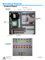
Control Panel
Spark generator
(120V–6000V)
Circuit relay A
Hour meter
Fuse 2 (3A—PLC)
Programmable
logic controller
(PLC)
Veri-Flame
control
Fuse 1 (5A)
Terminal block
Control Panel Cover
(non-modulating)
Armstrong International
IOM-706
Flo-Direct Water Heater
Page 19 of 45
Control Panel
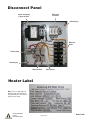
Disconnect Panel
Main fused
disconnect
Control transformer
(3 phase to 120V)
Grounding lug
Motor fuse
blocks
Terminal block
Grounding lug
Motor overloads
Motor starters
Heater Label
Note: This is a sample label. All
electrical work must conform to
the specifications on this label as
found on your heater.
Armstrong International
IOM-706
Flo-Direct Water Heater
Page 20 of 45
Heater Label
Electrical Connections
Note:
• Consult wiring schematic provided with your heater for exact details.
• Remove all cable ties, bubble wrap, and tape from wiring.
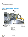
Top Plate to Upper Canister
Note: Sequence shown is
recommended, not required.
5 Reconnect threaded
fitting to burner flame
sensor port.
Modulating burner wiring
(may not be present)
4 Reconnect spark rod wire
to spark rod in burner.
1 Route blower motor
3 Route switch group
wiring through
conduit and into
disconnect panel.
2 In disconnect panel, connect
wires to motor overload
connection terminals below
motor starter.
Armstrong International
IOM-706
Flo-Direct Water Heater
wiring through
conduit and into
control panel.
Note: Wires are labeled.
Confirm labeling of starter by
checking for wire labeled 48A
below it.
Page 21 of 45
Electrical Connections
6 Reconnect water pressure switch
wiring on top plate to water pressure
switch on upper canister.
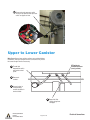
Upper to Lower Canister
Note: Depending on how canister sections were oriented during
installation, wires and conduit for these connections may not be
the correct length. Rewire if necessary.
RTD wiring for
modulating burner
(rarely present)
1 Thread high
temperature switch
wiring into control
panel.
2 Reconnect
conduit.
3 Connect wires to
corresponding
number locations in
terminal block.
4 Repeat for float
switch wiring from
standpipe.
Armstrong International
IOM-706
Flo-Direct Water Heater
Page 22 of 45
Electrical Connections
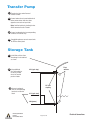
Transfer Pump
1 Thread wires into control box and
reattach conduit.
2 Connect motor wires to overload terminal
below motor starter with wire colors
opposite same color on input side.
Note: Confirm location by looking for wire
#83A connected to coil of starter.
3 Connect numbered wires to corresponding
terminals on terminal strip.
4 If modulating burner, connect second wire
for RTD to control panel.
Storage Tank
1 Install float switches from
Armstrong in tank oriented
as shown.
2 Using additional
Float
switches
#16 (cycle stop)
wire and conduit as
necessary, thread
wires into control
panel on heater.
1/2" half
coupling
3 Connect numbered
wires to corresponding
terminals on terminal
block.
#11 (cycle start)
#60 (power)
Armstrong International
IOM-706
Flo-Direct Water Heater
Page 23 of 45
Electrical Connections
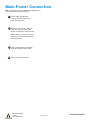
Main Power Connection
Note: If facility does not have surge and lightning protection,
Armstrong recommends both for heater.
1 Connect supply voltage to top
terminals of main fuse disconnect
inside disconnect panel.
2 Manually test each starter ("bump the
starter") to check for correct motor
rotation, as indicated on motor housing.
Note: If rotation is incorrect, change any
two phases on input side of applicable
starter and recheck.
3 Connect supply ground to grounding
lug at top right of disconnect panel.
4 Tighten all conduit connections.
Armstrong International
IOM-706
Flo-Direct Water Heater
Page 24 of 45
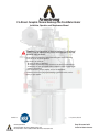
Electrical Connections
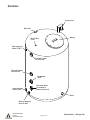
Operation
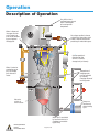
Description of Operation
Very efficient heat
exchange keeps exhaust
within a few degrees
of incoming water
temperature.
Water is dispersed
into upper canister
and is broken into
ever smaller droplets
by passing down
through palls.
Air and gas combine in burner
and enter dry flame tube, which
enables complete combustion
producing no undesirable gases.
System operation is
controlled by float
switches in remote
storage tank (not shown).
Water is heated as
combustion gases
pass up through
palls and out of
heater.
Temperature of
outgoing water
must be adjusted
by manually
changing volume of
incoming water.
Hot water
collects in
lower canister.
Pump runs
continuously
during heating
cycle.
Water level is controlled
by four float switches in
standpipe connected to
bypass loop.
Armstrong International
IOM-706
Flo-Direct Water Heater
Page 25 of 45
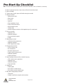
Sequence of Operation
Note: The description in this section assumes that the heater is in automatic mode —
"MANUAL/OFF/AUTO" switch set to "AUTO." If heater is equipped with modulating burner,
modulation control must display red “MANUAL” when heater is not running or it may not
start. Do not press “MANUAL” on the Powers controller thinking it must match heater's
mode! Once heater starts, Powers controller will switch to auto mode automatically.
Text in italics below is more specific information intended to aid in troubleshooting.
1 When low level float switch in remote storage tank calls for water (Wire #11; PLC input
0 energized), PLC will confirm that top float switch in lower canister (wire #20; PLC
input 8) is not in a fault condition and burner is in low fire position (wire #13; PLC
input 2), then energize control relay A (PLC output 0 energizes wire #81; control relay
contacts close).
Note: PLC is preset. Re-progamming it without written permission will void the
warranty and absolve Armstrong of all service commitments.
2 If low gas pressure, high gas pressure, and high temperature switches are all closed
(no fault conditions), power will be supplied to Veri-Flame controller (wire #47;
terminal 7 on Veri-Flame—"Interlocks closed" light will come on). (Any fault condition
will cause Veri-Flame control to shut down heater.).
3 If air pressure switch is open and fuel valve is closed, blower will start ("BLOWER ON"
lights; wire #48; terminal 8 on Veri-Flame).
4 Within a few seconds, air pressure switch must indicate adequate pressure ("AIR
FLOW" lights), then blower will initiate a 30-second purge (time is adjustable using
DIP settings on Veri-Flame).
5 Veri-Flame control allows fuel into burner ("FUEL ON" lights; Veri-Flame terminals 3
and 4 energize) and the spark rod to ignite it ("IGNITION ON" lights). Simultaneously
water valve opens ("WATER ON" lights).
6 When UV scanner confirms flame, Veri-Flame control (wire #45; terminal 5 on Veri-
Flame) energizes actuator:
• Non-modulating burner opens air and fuel dampers, and burner enters high-fire
setting.
• Modulating burner control changes from manual to auto mode allowing control to
track set point.
7 Veri-Flame control de-energizes spark rod ("IGNITION ON" off; wire #44; terminal 4 on
Veri-Flame).
8 Pump will start ("PUMP ON" lights; wire #18; PLC input 6) when water in lower
canister reaches second float switch.
9 During operation when correctly set, transfer pump bypass will cycle on (increasing
water flow; "BYPASS ON") and off keeping water level in lower canister between
middle float switches.
10 Once upper level switch in remote storage tank closes (wire #16; PLC input 4), PLC will
de-energize CR-A causing Veri-Flame control will turn off fuel valves. Blower will run for
several seconds to purge any remaining fuel.
11 If POC switch senses that fuel valve did not close completely, lockout valve will close
and blower will come on to purge any fuel.
Armstrong International
IOM-706
Flo-Direct Water Heater
Page 26 of 45
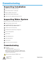
Pre-Start-Up Checklist
Note: This section to be performed by installer. Consult other information, such as schematics, as necessary.
Heater in permanent location on level surface sufficient for load and anchored
Heater assembled
Transfer pump (if used) in place with flexible water pipe connected
Wiring reconnected
• Water pressure switch
• Blower motor
• UV scanner
• Spark rod
• Burner modulation, if used
• Lower canister float switches
• High temperature switch
• Transfer pump
• Remote storage tank switches or field-supplied relay coil in control panel
Fuel line connected
• Adequately sized
• Adequately supported
• Pressure checked if required
• Purged
Water piping connected
• Sufficient inlet flow and pressure
• Adequately supported
• PRV if large pressure swings
Exhaust piping connected
• CPVC or stainless steel
• No unsealed joints
• No bends sharper than 45°
• Properly sized (no back pressure)
• Adequately supported
• Properly terminated
Intake air piping connected or filters installed if necessary
• CPVC, stainless steel, or galvanized
• Adequately sized
• Adequately supported
• Proper termination
Storage tank
• Properly piped
• Float switches installed correctly
• Float switches correctly wired to heater
Main power supply properly connected
• Three phase
• Voltage as specified on nameplate and connections
Armstrong International
IOM-706
Flo-Direct Water Heater
Page 27 of 45
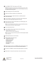
Commissioning
Inspecting Installation
1 Confirm all checks in start-up checklist above.
2 Check all field connections in control panels.
3 Identify any additional wiring in panels.
4 Confirm rotation of blower and pump motors.
5 Confirm what fuel is supplied and note label on fuel train.
Inspecting Water System
Note: Run cold water first to prevent damage in lower canister.
1 Jump valve to bypass automatic control.
2 Turn "MANUAL/OFF/AUTO" switch on control panel to
"MANUAL," but do not press "MANUAL START."
3 Set water inlet pressure to about 20 psi.
4 Set outlet pressure at pump to 40 psi, with bypass off.
5 Visually confirm proper flow.
6 Check for leaks.
7 Confirm adequate pressure.
8 Confirm pump operation.
9 Close water valve.
10 Set main water valve to normal operation.
Commissioning
1 Turn on fuel.
• Check for leaks in piping
• Verify that gas pressure is between 2 and 7 psi
Note: Start-up process requires running heater in "MANUAL" mode,
which overrides all automation and produces hot water continuously
until heater is manually turned off.
Never leave heater unattended in "MANUAL" mode.
Armstrong International
IOM-706
Flo-Direct Water Heater
Page 28 of 45
Commissioning
2 Press "MANUAL START." Verify input zero on PLC lights.
Note: During initial start-up, low gas pressure fault light may come on. Once
pressure is established, reset pressure switch. Several attempts to start may
be required until fuel enters burner.
3 Verify that output zero on PLC and relay A light.
4 Confirm that Veri-Flame controller has a solid green light.
5 Verify that burner goes to high fire after flame is established and VeriFlame indicates flame.
6 Check temperature on gauge above transfer pump. Adjust incoming water
pressure to obtain target output temperature if necessary.
7 Adjust throttling valve above transfer pump to cycle solenoid (bypass) and
maintain water level in heater.
Note: Level should fluctuate slowly between second and third float switches
without seeing a tank-full fault or pump turning off.
8 Check exhaust piping for leaks.
9 Insert combustion analyzer in port in exhaust stack and tune heater.
• Oxygen reading must be 3.5–6%
• Adjust for minimum carbon monoxide (CO)
Note: Low efficiency may be due to back pressure in exhaust piping if opening
at cap is too small.
10 Record regulator pressure on fuel train label.
11 Confirm operation of all safety features:
•
•
•
•
•
•
•
Low gas pressure switch
High gas pressure switch
Proof of closure switch
Low water pressure
High temperature
Flame failure (UV scanner)
False flame
12 Perform at least ten start cycles in "MANUAL" mode, allowing heater to reach
high fire condition each time, to ensure reliable starting and operation.
13 Run heater in "AUTOMATIC" mode to confirm proper operation in that mode.
14 Allow heater to sit and cool for several hours, then check for cold start.
Armstrong International
IOM-706
Flo-Direct Water Heater
Page 29 of 45
Inspecting Installation
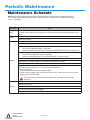
Periodic Maintenance
Maintenance Schedule
Note: Periodic maintenance for blower and burner is not shown below. See those IOMs for required maintenance.
The Flo-Direct heater is designed to require very little maintenance. The list below is recommended, but only safety
items (*) are required.
Frequency
Task
Check output temperature (non-modulated). (To change, adjust water flow valve slowly and in small
increments allowing time for change to take effect. Increase water flow to decrease temperature and vice
versa).
Daily
Weekly
Check air filters if present. Clean or replace as necessary (see manufacturer's information).
Check for water leaks.
Check fuel train for leaks.
Remove and wipe off quartz lens below flame sensor.
*Check water pressure switch:
• Turn off water supply while heater is in operation
• Confirm that heater shuts down within 10 seconds and "WATER PRESSURE FAULT" light comes on
*Check low gas pressure switch:
• Turn off the fuel supply while heater is in operation
• Confirm that heater shuts down and "LOW GAS PRESSURE" fault light comes on
Monthly
*Check high temperature switch (see instructions below).
Inspect burner’s air damper linkage (use a borescope through burner’s window).
Check spark rod connection and wire.
*Check the Veri-Flame controller:
With heater running, close ball valve in fuel train just upstream of burner.
• Burner should go out
• Veri-Flame control should show no indication of flame
• Control should de-energize safety shut-off valves (there will be a "clunk" sound as valves close; some
models also have indicator lights)
If results are not as described, a hazard condition exists. Shut down heater and contact
Armstrong.
Check all electrical connections.
Check all nuts and bolts.
Annually
Check float switches for proper operation.
Check all fuel train connections and fittings.
Check all water train connections and fittings.
Armstrong International
IOM-706
Flo-Direct Water Heater
Page 30 of 45
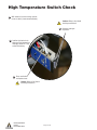
High Temperature Switch Check
1 With heater on but not running, unscrew
cover on switch (shown removed below).
Caution: Wiring is live! Avoid
touching connections!
2 Compress spring to
trip switch.
3 Confirm that heater shuts
down and high temperature
fault light comes on. If not,
contact Armstrong.
4 Press reset button
and replace cover.
Caution: Wiring is live! Avoid
touching connections!
Armstrong International
IOM-706
Flo-Direct Water Heater
Page 31 of 45
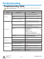
Troubleshooting
Troubleshooting Table
Note: Turn off power to heater prior to beginning. During troubleshooting, turn it on only when and only for as long as
required for specific steps below.
Troubleshooting
Problem
Actuator Fault
Flame Safety Fault
Low Gas Pressure
High Gas Pressure
Armstrong International
IOM-706
Flo-Direct Water Heater
Probable Cause
Correction
Transitory alarm or to confirm fault
Turn "AUTO/OFF/MANUAL" switch to "OFF" then to
"AUTO" (or "MANUAL" if using that mode).
Start attempt without actuator in low fire
position
Confirm that switch on burner arm is in contact and
closed.
Heater with modulating burner not in
"MANUAL" state at start-up attempt
Press "ACTUATOR RESET" on control panel if it exists.
OR
Unplug and replug "d-out" relay in control panel.
Transitory alarm or to confirm fault
Press reset button twice on Veri-Flame controller inside
control panel (button must be out). If fault recurs,
continue.
Flame failure
Check spark rod wiring and connection for breaks,
arcing, or carbon fouling.
Check UV scanner for dirt and reaction to flame.
Air failure
Check air flow switch:
• Disconnection
• Plugged sensor tube
• Defective
Check blower overloads:
• Electric current setting. Adjust or reset.
• If fault recurs, check 3-phase wiring.
• If fault persists, check blower motor coil impedance.
System error
Check adjustment of POC switch.
Check gas valve for proper operation.
Transitory alarm or to confirm fault
Press red reset button on low gas pressure switch on
fuel train.
Upstream fuel valve closed
Open all upstream valves.
Defective pressure regulator spring
Replace spring.
Defective pressure regulator
Replace regulator.
Transitory alarm or to confirm fault
Press red reset button on high gas pressure switch on
fuel train.
Regulator pressure set too high
Turn regulator adjustment screw CCW to reduce
pressure.
Defective pressure regulator spring
Replace spring.
Defective pressure regulator
Replace regulator.
Page 32 of 45
Troubleshooting Table
Troubleshooting
Problem
Probable Cause
High Temperature Fault
Contact Armstrong!
Do not operate
heater!
Tank Full Fault:
Pump not keeping up with
water production
Water Pressure Fault
Modulating burner does
not enter automatic
mode and track set-point
("MANUAL" stays lit after
flame is established)
Correction
Water pressure switch failed and "dry fire"
start-up attempted
Check water pressure. If correct, replace pressure
switch. If not, continue.
Nozzles clogged
Remove top plate and clean nozzles.
Transfer pump throttling valve out of
adjustment
Readjust valve.
Transfer pump and/or bypass inoperable
Check and repair or replace.
Downstream valves closed or restricted
Confirm that all downstream valves are fully open.
Flow control valve restricted
Open flow control valve.
Shut-off valve defective
Repair or replace valve.
Restriction in inlet line
Check filters and piping for obstructions.
Low system pressure
Correct system pressure.
Reset button on Veri-Flame control is
pressed in
Press reset button on Veri-Flame control (button must
be in up position.
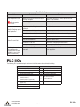
PLC I/Os
The following PLC inputs and outputs are shown to facilitate more advanced troubleshooting.
0
1
2
3
4
5
6
7
8
9
Inputs
Momentary start (auto or manual)
Spark ignition on
Actuator in low fire position
Water pressure switch
Storage tank full (auto stop)
Lower canister bottom float switch
(transfer pump off)
Lower canister second float switch
(transfer pump on, bypass off)
Lower canister third float switch
(bypass on)
Lower canister float top float switch
(tank full fault)
Flame detected (main fuel supply on)
Armstrong International
IOM-706
Flo-Direct Water Heater
0
1
2
3
4
Outputs
CR-A on; permission to start heater
Water supply on
Transfer pump on
Transfer bypass on
Water pressure switch fault
5
Lower canister full fault
6
Actuator switch fault
7
General alarm
Page 33 of 45
PLC I/Os
Parts Lists
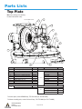
Top Plate
Note: Some wiring in this drawing
has been removed for clarity.
7 & 8 installed in union
6
7
10
8
5
1
2
3
4
9
12
11
Ref No.
—
1
2
3
4
5
6
7
8
9
10
Description
Spark Plug Wire, 7 mm, SCS7-100
Spark Rod, #47232
Plug End Connector, Strt, ST113
Spark Plug Boot, Belden
Cord grip, ½″, Appleton CG1850
Low Fire Limit Switch
Veri-Flame, UV Scanner, 90
O-Ring, Viton, 7/8″ x 1″
Quartz lens, 1″ Dia x 1/16″
Air Pressure Switch, 1950-5-2F
Burner Actuator
Actuator, EMA-405-1, Standard
Actuator, EMP-424-1, Modulating
Part No.
D17513
D19194
D17386
D27110
D16992
D19195
D16915
D17086
D17085
D16919
Ref No.
11
D16978
D17141
12
Description
Part No.
Flange Gasket – WARCO White
AFD-1000
D7564
AFD-1500
D7565
AFD-2000
D7566
AFD-3000
D7567
AFD-4000
D7568
AFD-5000
D7569
AFD-6000
D7570
AFD-7000, 8000
D7571
AFD-9000 to 12000
D7576
AFD-13000 to 16000
D7579
Flame Shield
AFD-1000 & 1500
D27182
AFD-2000
D27183
AFD-3000 & 4000
D27184
AFD-5000 to AFD-16000
D26712
For burner parts, contact MAXON Corp., 765-284-3304 (fax: 765-286-8394)
For blower assembly parts, contact Cincinnati Corp., 513-573-0600 (fax: 513-573-0640)
Armstrong International
IOM-706
Flo-Direct Water Heater
Page 34 of 45
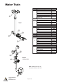
Water Train
Ref No.
Description
Ball Valve - Bronze
1″
D10182
1-1/2″
D9341
2″
D10275
2-1/2″
D18754
1
3″
D10184
4″ (Actuated Cast Iron/Carbon Steel
D27041
Butterfly Valve)
Weathermatic Valve
1″
D19190
1-1/2″
D19191
2″
D18331
2
2-1/2″
D18722
3″
D19192
4″ (Cast Iron/Carbon Steel Globe Valve)
D19193
Weathermatic Valve Diaphragm Assembly
1″
D8655
1-1/2″
D8656
—
2″
D8657
2-1/2″
D8658
3″
D8659
3
Solenoid, SOL–7, 110V
D18330
4
Pressure Gauge, 0–110 psi
D11554
5
Water Pressure Switch
D16905
Actuated Butterfly Valve Assembly – Clamp Ends
1″
D14602
1-1/2″
D14623
2″
D14624
6
2-1/2″
D14625
3″
D14626
4″
D14627
Electric Actuator for Stainless Butterfly
D27044
Globe Valve, Stainless Steel
1″
D14596
1-1/2″
D14597
2″
D14598
7
2-1/2″ (flanged)
D14599
3″ (flanged)
D14600
4″ (flanged)
D14601
Copper
Welded
Stainless Steel
Note: Weathermatic valve may
be used on stainless steel train.
Armstrong International
IOM-706
Flo-Direct Water Heater
Part No.
Page 35 of 45
Control Box
Ref No.
1
2
3
4
5
6
Description
Part No.
Powers Controller, 5351112ABD0
D19408
Contact, Push Button Operator
D15647
Switch, Operator 3-Position
D19152
Panel Lens Set (7 Red, 4 Green, 4 Amber)
D8647
Latch, Metal, 800FALM AB 800F
D19153
LED White for Pilot Light
D47372
Control Label set (For All Indicator Lights And
7
D19188
Switches)
8
Relay, 4 Pole, Double Throw
D16903
9
Base Socket, Mini, 14 Blade
D16886
Flame Safety Module
Eclipse Veri-Flame 5605-22 (US)
D19186
10
Eclipse Veri-Flame CSA 5605-22AA (Canada)
D19187
11
D19554
Grommet, 7/8″ ID
12
Base Terminal Veri-Flame
D19332
13
Ignition
D19185
34 Transformer 120/6000
14
Hour Meter UWZ 48V
D19184
15
Fuse Block
D10787
Circuit Block, IEC, Single Feed
Gray
D10789
16
Blue
D6058
17
Fuse, AGC 5A
D19587
18
Fuse, AGC 3A
D19586
Programmable Logic Controller (PLC) AFD Program Loaded
Allen Bradley Micrologix 1200
D19106
Allen Bradley Micrologix 1100 (Requires Output
19
D22729
Module 1762-OW8)
Allen Bradley PLC, Output Module, 1762-OW8
D22730
Armstrong International
IOM-706
Flo-Direct Water Heater
Page 36 of 45
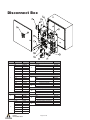
Disconnect Box
1
8
13
2
9
12
11
10
6
5
1
3
7
4
Ref No. Description
Part No.
Fuse, Low Peak, Class J
3A
D19610
5A
D17885
7A
D19611
10A
D19612
12A
D19613
15A
D19614
17 1/2A
D19615
20A
D19616
1
25A
D19617
30A
D19618
35A
D19619
40A
D19620
50A
D19621
60A
D19622
70A
D19623
80A
D19624
100A
D19625
Fuse, Class CC, FNQ-R
6A
D21849
2
8A
D19763
15A
D18692
Motor Starter
5 HP
D7655
7 1/2 HP
D7656
10 HP
D7657
15
HP
D7658
3
20 HP
D7659
25 HP
D7660
30 HP
D7661
Armstrong International
IOM-706
Flo-Direct Water Heater
Ref No.
4
5
6
7
8
9
10
11
12
13
Description
Motor Overload
1.6–5A
3.2–16A
5.4–27A
9–45A
Relay, 4 Pole, Double Throw
Base Socket, Mini, 14 Blade
Fuse Cover, Bus, Indicating
30A
60A
100A
Fuse Cover, Bus, Non-Indicating
Disconnect Handle
30A & 60A
100A
Connecting Rod, Disconnect
30A & 60A
100A
Circuit Block, IEC, Single Feed
Fused Disconnect
30A
60A
100A
Control Voltage Transformer
750VA 480 x 240 – 120
750VA 575/380 – 115
Page 37 of 45
Part No.
D17910
D7663
D7664
D7665
D16903
D16886
D19762
D22629
D21900
D17413
D15638
D21901
D17218
D21902
D10789
D17179
D19671
D21903
D17409
D13662
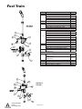
Fuel Train
Ref No.
1
2
AFD-5000 to
AFD-16000
3
4
5
6
7
8
9
10
11
AFD-1000 to
AFD-4000
Armstrong International
IOM-706
Flo-Direct Water Heater
Page 38 of 45
Description
Gas Rated Ball Valve
AFD-1000 and AFD-1500 (1″ NPT)
AFD-2000 and AFD-3000 (1-1/2″ NPT)
AFD-4000 to AFD-10000 (2″ NPT)
AFD-11000 to AFD-16000 (3″ NPT)
Pressure Gauge, 0–15 psi
Gas Pressure Regulator
AFD-1000 to AFD-4000 (FRI 710/6)
AFD-5000 to AFD-10000 (FRS 720/6)
AFD-11000 to AFD-16000 (FRS 730/6)
Gas Regulator Spring
AFD-1000 to AFD-4000 Yellow 12″–28″ w.c.
AFD-1000 to AFD-4000 Black 24″–44″ w.c.
AFD-5000 to AFD-10000 Yellow 12″–28″ w.c.
AFD-5000 to AFD-10000 Black 24″–44″ w.c.
AFD-5000 to AFD-10000 Pink 40″–60″ w.c.
AFD-11000 to AFD-16000 Yellow 12″–28″ w.c.
AFD-11000 to AFD-16000 Black 24″–44″ w.c.
AFD-11000 to AFD-16000 Pink 40″–60″ w.c.
AFD-11000 to AFD-16000 Gray 56″–80″ w.c.
Dual Blocking Valve Assembly
AFD-1000 to AFD-4000 (DMV-D 703/11)
AFD-5000 to AFD-10000 (DMV-D 525/11)
AFD-11000 to AFD-16000 (DMV-D 5080/11)
Low Gas Pressure Switch 12″–60″ w.c.
(GMH-A2-4-6)
High Gas Pressure Switch
AFD-1000 to AFD-14000 12″–60″ w.c.
(GMH-A2-4-6)
AFD-15000 to AFD-16000 40″–200″ w.c.
(GMH-A2-4-8)
Visual Proof of Closure Indicator
Electrical Proof of Closure Indicator (CPI-400)
DIN Connector (D210319)
Pressure Gauge, 1″–100″ w.c.
Part No.
D15432
D15433
D15434
D15435
D14800
D14806
D14807
D14808
D11555
D14809
D19189
D14810
D12543
D11559
D14811
D12336
D12142
D14823
D14824
D14825
D11538
D14829
D12335
D11573
D14826
D14827
D14828
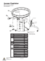
Lower Canister
Note: This drawing is a composite.
Not all parts are present in every
heater configuration.
All 4 float switches
swing downward
Secured to
float switches
(pumped only)
Gravity drain
For pumped
units only
Ref No.
1
2
3
4
5
6
7
8
9
Armstrong International
IOM-706
Flo-Direct Water Heater
Description
Float Switch, Polypropylene
High Temp Shutoff Switch, 600 °F
Standpipe Cap
RTD Temp Sensor
1-1/2″, 100Ω
2″, 100Ω
3″, 100Ω
5″, 100Ω
Drain Plug, 1″ NPT, 304 SS
Plug, ½″ NPT, 304 SS
Wiring Trough Drilled for Standpipe
SS Braided Flex Hose, Clamp Ends
1-1/2″ Dia x 36″ long
2″ Dia x 36″ long
3″ Dia x 36″ long
4″ Dia x 36″ long
Flange Gasket – WARCO White
AFD-1000
AFD-1500
AFD-2000
AFD-3000
AFD-4000
AFD-5000
AFD-6000
AFD-7000 & 8000
AFD-9000 to AFD-12000
AFD-13000 to AFD-16000
Page 39 of 45
Part No.
D16907
D16916
D18110
D13273
D10210
D17584
D27358
D16918
D11018
D17265
D15722
D15723
D15724
D15725
D7564
D7565
D7566
D7567
D7568
D7569
D7570
D7571
D7576
D7579
Modulating burner with
gravity drain only. If
pumped, RTD is installed
in transfer pump package.
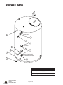
Storage Tank
Float switch
swings down
Float switch
swings up
Check wiring schematic
for float switch orientation
Ref No.
1
2
3
4
5
Armstrong International
IOM-706
Flo-Direct Water Heater
Page 40 of 45
Description
Bushing, CPVC 4″ x 1/2″ NPT
Float Switch, Polypropylene
Thermometer, Back Mount, 4″ Stem
Plug, 2″ NPT, 304 SS
Plug, 1″ NPT, 304 SS
Part No.
D18785
D16907
D8969
D18789
D16918
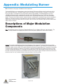
Appendix: Modulating Burner
Note: information on this page is intended for technical personnel.
The standard Flo-Direct uses a powered open, spring-closed actuator. The burner will light on low fire and then go to fully
open or the high fire position. The heater’s output is only the full rated BTUs of the Flo-Direct. Sometimes it is necessary
to vary this output. To accomplish this task, the burner’s output can be modulated. The modulating option consists of
a 90-degree movement actuator, a programmable controller, and an RTD temperature sensor. The burner’s firing rate is
changed by the actuator moving a control arm on the burner that is mechanically linked to both an air and a fuel butterfly
damper. The burner will still light on low fire, but after the flame is established, the controller will open and close the burner’s
damper so as to track the set point. If the output is less than the set point, the controller will open the actuator until the
output matches the desired set point. When the Flo-Direct’s flame is shut off, the controller will go into manual mode and 0%
output, ready to start again.
Descriptions of Major Modulation
Components
RTD: The temperature sensor is a Resistance Temperature Detector. This is a 100-ohm, DIN curve, three-wire device. The
sensor is usually mounted in the outgoing water, either in the transfer pump’s piping or the lower canister assembly.
Actuator: The actuator is a bidirectional motor that has 90 degrees of arm movement. The motor will drive the arm either
clockwise or counter clockwise depending on the position desired by the controller. A “dry” contact in the controller will close
to drive the actuator one way, another “dry” contact will drive the controller the opposite direction. The position of the actuator
is sent back to the controller via a slidewire. This slidewire is a 100-ohm potentiometer with a wiper arm that will vary from
2–3 ohms to slightly over 100 ohms. If, for example, the controller desires a 50% open actuator, a contact will close to drive
the motor one way until the resistance is equal between the wiper arm and the fully open and fully closed resistance. Once the
resistance is even, the “dry” contacts will open, leaving the actuator in the 50% position.
Armstrong International
IOM-706
Flo-Direct Water Heater
Page 41 of 45
Controller: The controller is a Powers 535-1112ABD000 model. This is a fully programmable controller that must be programmed
in order to work with the Flo-Direct. These are all pre-programmed and tested before leaving the factory, however, if a
replacement controller is installed, the new will have to be programmed as specified in the documentation sent with the FloDirect.
This controller has three “dry” contacts and a 4-20 mA DC output, two of the “dry” contacts are to drive the actuator one way or
the other, a spare “dry” contact is available for use as an alarm, etc. A 4-20 mA DC output is available to transmit various analog
values such as set point, process variable, etc.
The input is set via internal jumpers for an RTD. In addition, there are five special contacts that can cause the controller to
perform various functions. The designated output (“d-out”) function is always used. When this “dry” contact is closed, the
controller will go to manual mode and 0% output. The controller must be in this mode and output in order for the Flo-Direct to
start. Other special functions are possibly as a second set-point and possibly the ability to accept a remote set-point. Please refer
to the specific program listing, electrical schematic, and the Powers manual for more detail.
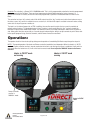
Operation:
The operator should not have to do anything during normal operation of a modulating Flo-Direct except change the set-point.
NOTE 1: The operating modes of the heater and Powers controller (modulation) are independent. When the heater is in "AUTO"
mode, the Powers controller must be in manual mode when the heater is not running; once flame is established, it will switch to
auto mode. When the heater turns off, it will switch back to manual mode. Do not adjust the "MANUAL" button on the Powers
controller.
Heater in "AUTO" mode
not running
Heater in "AUTO" mode
running
Powers controller
must be in
"MANUAL" mode.
Heater in "AUTO"
mode
Armstrong International
IOM-706
Flo-Direct Water Heater
Page 42 of 45
If the button is pushed, then the controller will try to open the burner to track the set point, but since there is no
flame, the controller will drive the burner to the fully open position. Then the unit will not light because the burner
is not in the starting (low fire) position. To restore the controller to normal, the circuit for the d-out must be opened
and reclosed. On some Flo-Directs there is a button on the panel for actuator reset; on others the relay in the
control box must be unplugged and re-plugged (opening and reclosing) the d-out circuit. All of the above can be
avoided if the controller is not taken out of “MANUAL” and not switched to “AUTO” when the flame is off. Leave the
“MANUAL” button alone.
NOTE 2: If the heater is running and the controller does not switch from manual to auto mode and begin tracking
the set point (red “MANUAL” light is lit long after the flame is on), then the Veri-Flame controller (green flame
safety inside of control panel) has been improperly reset. The reset button must be in the “out” position. If this
button is pushed once and not twice, then the Powers Controller will not be released to go to high fire.
For additional information please see the Powers Controller program listing, the electrical schematic, and the
Powers Controller manual.
Armstrong International
IOM-706
Flo-Direct Water Heater
Page 43 of 45
Limited Warranty and Remedy
Armstrong Hot Water, Inc. ("Armstrong") warrants to the original user of those products supplied by it and used in the service and
in the manner for which they are intended, that such products shall be free from defects in material and workmanship for a period
of one (1) year from the date of installation, but not longer than 15 months from the date of shipment from the factory [unless a
special warranty period applies, as listed below]. This warranty does not extend to any product that has been subject to misuse,
neglect, or alteration after shipment from the Armstrong factory. Except as may be expressly provided in a written agreement
between Armstrong and the user, which is signed by both parties, Armstrong DOES NOT MAKE ANY OTHER REPRESENTATIONS
OR WARRANTIES, EXPRESS OR IMPLIED, INCLUDING, BUT NOT LIMITED TO, ANY IMPLIED WARRANTY OF MERCHANTABILITY
OR ANY IMPLIED WARRANTY OF FITNESS FOR A PARTICULAR PURPOSE. The sole and exclusive remedy with respect to the
above limited warranty or with respect to any other claim relating to the products or to defects or any condition or use of the
products supplied by Armstrong, however caused, and whether such claim is based upon warranty, contract, negligence, strict
liability, or any other basis or theory, is limited to Armstrong's repair or replacement of the part or product, excluding any labor
or any other cost to remove or install said part or product, or, at Armstrong's option, to repayment of the purchase price. As a
condition of enforcing any rights or remedies relating to Armstrong products, notice of any warranty or other claim relating to
the products must be given in writing to Armstrong: (i) within 30 days of last day of the applicable warranty period, or (ii) within
30 days of the date of the manifestation of the condition or occurrence giving rise to the claim, whichever is earlier. IN NO EVENT
SHALL ARMSTRONG BE LIABLE FOR SPECIAL, DIRECT, INDIRECT, INCIDENTAL OR CONSEQUENTIAL DAMAGES, INCLUDING,
BUT NOT LIMITED TO, LOSS OF USE OR PROFITS OR INTERRUPTION OF BUSINESS. The Limited Warranty and Remedy terms
herein apply notwithstanding any contrary terms in any purchase order or form submitted or issued by any user, purchaser, or third
party and all such contrary terms shall be deemed rejected by Armstrong.
Special Warranty Periods are as follows:
• The stainless steel structure and stainless steel internals (flame tube, pall rings, supports, etc.): Ten (10) years from the date of
installation, but not longer than one hundred twenty-three (123) months from the date of shipment, provided only clean potable
water is heated and commercially available fuel is used.
• The other components on the Flo-Direct, such as valves, combustion equipment, electrical controls, and the burner: Two (2)
years from the date of installation, but not longer than twenty-six (26) months from the date of shipment.
Armstrong International
IOM-706
Flo-Direct Water Heater
Page 44 of 45
Notes
Armstrong International
IOM-706
Flo-Direct Water Heater
Page 45 of 45