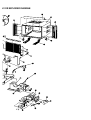
1
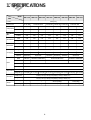
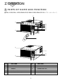
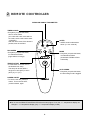
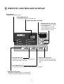
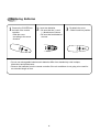
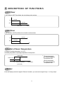
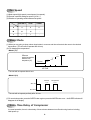
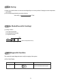
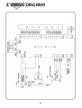
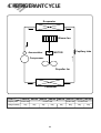
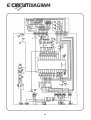
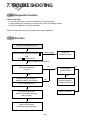
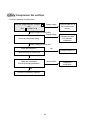
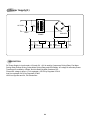
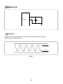
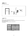
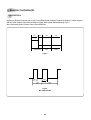
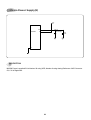
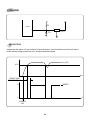
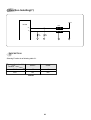
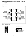
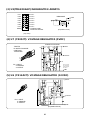
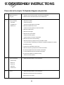
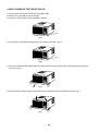
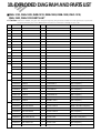
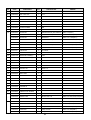
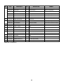
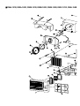
Manual de Servicio
Acondicionador de Aire Tipo Ventana
Modelo : DWC-121R
DWA-121R
DWA-122R
DWB-121R
DWB-122R
DWB-123R
DWA-150R
DWA-151R
Contents
CONTENTS
1. Specifications ................................................................................................2
2. Operation .....................................................................................................3
3. Wiring Diagram..........................................................................................10
4. Refrigerant Cycle .........................................................................................11
5. Control Block Diagram.................................................................................12
6. Circuit Diagram..........................................................................................13
7. Trouble Shooting..........................................................................................16
8. Key Components of Electronic Circuit ............................................................26
9. Disassembly Instructions ...............................................................................28
10. Exploded Diagram and Parts List...................................................................30
1
1. SPECIFICATIONS
MODEL
ITEM
DWC-121R
DWA-121R
DWA-122R
Function
DWB-121R
DWB-122R
DWB-123R
DWA-150R
DWA-151R
Cooling only
Power source
AC 115V, 60Hz
AC 208~230V, 60Hz
AC 220~240V, 50Hz AC 220~230V, 50Hz AC 240V, 50Hz
AC 208~230V, 60Hz
Btu/h
12,100
12,000
12,000
11,700
12,000
11,500
14,018
14,000
Kcal/h
3,050
3,024
3,024
2,950
3,024
2,898
3,533
3,528
Btu/wh
10.1
10.2
10.1
9.9
10.0
10.0
9.4
9.8
Kcal/wh
2.55
2.57
2.55
2.49
2.52
2.52
2.38
2.47
Pts/h
3.40
3.61
3.14
3.30
2.66
2.71
4.04
3.93
g/h
1,545
1,640
1,427
1,500
1,209
1,232
1,836
1,786
Power Input (W)
1,200
1,175
1,184
1,180
1,150
1,150
1,487
1,420
Running Current (A)
11.5
5.5
5.5
5.2
5.4
5.4
6.7
6.5
QK196PN13A
RBB110A011
RBF110A011
QJ196KC23B
RCA135A001
35µF/400VAC
30µF/400VAC
35µF/400VAC
Cooling Capacity
Energy Efficiency
Ratio
Dehumidification
Electrical Data
Type
Compressor
Rotary
Model
QK164CN12
Capacitor
40µF/370VAC
Model
Capacitor
QK164KN12
RBA115A001
25µF/370VAC
AM12DWD10-1/
OBM-2501K AM12DWD12-1/OBM-2502U1
12µF/370VAC
25µF/370VAC
A2925CA070/OBM-2501P2
AM12DWD11-1/OBM-2503U1
5µF/400VAC
4µF/370VAC
5µF/370VAC
Motor
Indoor-Fan
Blower-Fan
Outdoor-Fan
Propeller-Fan
Control
Capillary
Refrigerant(R-22)
Charge Q’ty (g) 24.0 oz (680 g) 26.1 oz (740 g) 27.9 oz (790 g) 25.7 oz (730 g) 24.3 oz (690 g) 26.8 oz (760 g) 27.9 oz (790 g) 27.5 oz (780 g)
Unit(W x H x D)
23.6(W) x 14.9(H) x 21.0(D) inch (600(W ) x 380(H) x 535(D) mm)
Packing(W x H x D)
26.1(W) x 18.1(H) x 22.6(D) inch (663(W ) x 460(H) x 573(D) mm)
Dimensions
Net Weight
88 lbs (38.8Kg)
88 lbs (38.8Kg)
90.2 lbs (39.8Kg)
92 lbs (42Kg)
Gross Weight
89 lbs (40.3 Kg)
89 lbs (40.3 Kg)
97.5 lbs (43Kg)
96 lbs (43.5Kg)
Weight
2
2. OPERATION
1 PARTS OF NAME AND FUNCTION
● DW*-121R/DW*-122R/DWB-123R/DWA-150R/DWA-151R (NOTE:* ➔ A or B or C)
9
3
0
7
q
4
8
2
1
5
6
3
7
4
8
2
5
1
NO
PART NAME
NO
1
AIR FILTER
7
BLADE HORIZENTAL
2
GRILLE FRONT
8
AIR VENT
3
CABINET
9
FRAME GUIDE TOP
4
BLADE VERTICAL
10
FRAME WINDOW KIT
5
PANEL CONTROL
11
SHUTTER WINDOW
6
REMOTE CONTROLLER
3
PART NAME
2 REMOTE CONTROLLER
REMOCON SIGNAL TRANSMITTER
TIMER/CANCEL
• Everytime you push this button,
timer is set as follow.
(1Hr→2Hr→3Hr→4Hr→5Hr→6Hr→8
Hr→10Hr→12Hr→16Hr→20Hr→24Hr
→CANCEL).
After the unit is timed, if this button is
pushed, timer is canceled.
TIMER/
CANCEL
FAN SPEED
SLEEP
• SLEEP mode is selected as
follow. (L1→L2→Cancel)
SLEEP
AUTO
SWING
FAN SPEED
• Everytime you push this button,
it is selected as follow.
(High→Mid→Low→High)
TEMP
TEMPERATURE
• It is the button to set the room in
the desired room temp.
The temp can be set within a
range from 16°C (60°F) to 32°C
(90°F) by 1°C (1°F)
MODE
MODE
• Everytime you push this button,
it is selected as follow.
(COOLING→TURBO→FAN→
COOLING)
AUTO SWING
• Everytime you push this button,
the auto swing mode is toggled.
POWER ON/OFF
• To turn the unit ON, push this
button. To turn the unit OFF,
push this button, again.
✽ Do not use the REMOTE CONTROLLER before the lamp lights. If use, the “ °F ” temperature display can
change to “ °C ” temperature display (only “°F” temperature display model).
4
3 REMOTE CONTROLLER DISPLAY
MODE DISPLAY
• It displays the operating mode.
TEMP./TIMER DISPLAY
• It displays the temperature and the timer.
REMOCON SIGNAL RECEIVER
TEMPERATURE SET BUTTON
• It is the button to set the desired
room temperature.
The temperature can be set
within a range from 16°C (60°F)
to 32°C (90°F) by 1°C (1°F)
88
Room Air-conditioner
FAN
ROOM TEMP
TURBO
DESIRED TEMP
COOLING
TIMER
MODE
FAN
SPEED
AUTO
SWING
FAN SPEED BUTTON
• Everytime you push this button, It is selected as
follow. (High→Mid→Low→High)
SENSOR
TEMP
POWER
POWER ON/OFF BUTTON
• To turn the unit ON, push this button.
To turn the unit OFF, push this button
again.
AUTO SWING BUTTON
• Everytime you push this button, the auto swing mode is toggled.
MODE SELECT BUTTON
• Everytime you push this button, It is selected as
follow. (COOLING→TURBO→FAN→COOLING)
5
Replacing Batteries
1
Remove the COVER from
the back of the remote
controller.
• Slide the cover
according to the arrow
direction
2
Insert two battaries.
• Be sure that the (+) and
(–) directions are correct
• Be sure that both batteries
are new
–
+
3
Re-attach the cover.
• Slide it back into position
+
–
• Do not use rechargeable batteries such batteries differ from standard dry cells in shape,
dimensions and performance.
• Remove the batteries from the remote controller if the air conditioner is not going to be used for
an extended length of time.
6
4 DESCRIPTION OF FUNCTIONS
OFF-Timer
If you set time in OFF-Timer Mode, the unit will stop at the set time.
ON
Unit ON
Unit OFF
OFF
SET Time
HOUR
ON-Timer
If you set time in ON-Timer Mode, the unit will run at the set time.
Unit ON
ON
Unit OFF
OFF
SET Time
HOUR
Control of Room Temperature
(1) Range of setting temperature: 16~32°C
(2) Setting temperature: Operating temperature of compressor
COMP (ON)
*
COMP (OFF)
-1˚C
Desired temperature
Temperature
(
(
Room temperatrue
< setting temperature
Compressor OFF
Room temperature
> setting temperafure
Compressor ON
(COOLING)
Buzzer
If the Unit Display receive the signal of Remote Controller, you can hear the signal "beep –" or "beep, beep".
7
Fan Speed
(1) Motor speed (high speed, normal speed, low speed).
(2) Remote controller setting fan speed. (H, M, L)
(3) Relation of operating mode between fan speed.
FAN ONLY
COOL
TURBO
H
H
H
H
M
M
M
-
L
L
L
-
Sleep Mode
(1) When you are going to sleep, select sleep button in remocon and the unit controls the room to the desired
temperature. (The unit will not operate after 4 hour)
(2) For changing the temperature.
• Mode I (L1)
Difference
desired temperature
between room
temperature (°C)
0.5°C
1°C
1
0.5°C
1
0.5°C
1°C
1
Desired
Temperature
1°C
0
0.5
SET TIME
1.0
HOUR
• The unit will not operate after 4 hour.
• Mode II (L2)
Desired
+1˚C
SET ON
SET OFF
2hr
2hr
2hr
Temperature
+1˚C
2hr
2hr
• The unit will not operate perfectly after 10 hour.
(3) To cancel sleep mode, press the SLEEP button again or press the MODE button once. : the SLEEP indicator will
disappear in the display.
3min. Time Delay of Compressor
In normal operation, there is a time delay of three minutes between turn off and turning back on including
initial power up.
8
Auto Swing
(1) When you push this button, in remocon the left/right flap move to the position of keeping the room temperature
comiortable.
(2) The air discharge direction procedure is below.
Auto swing
Fixed
Turbo Mode(Powerful Cooling)
(1) Cooling Condition
1 Fan Speed: High speed
2 Set temperature:16˚C(Fixed)
3 Compressor and Fan
ON
OFF
(Room temperature-18˚C)
-1
0
1
Self-Diagnostic Function
The control will contain diagnostic test to verify the integrity of the system.
(1)Error Code Display
ERROR CODE
88 LED DISPLAY
ERROR CONTENTS
1
Room air thermistor short or open.
9
3. WIRING DIAGRAM
10
4. REFRIGERANT CYCLE
Evaporator
Blower fan
M
Accumulator
Capillary tube
MOTOR
Compressor
Propeller fan
Condenser
Model Name
Contents
Capillary tube
Charge Quantity
DWA-121R
DWA-122R
ID1.6Ø x L800
740g
DWB-121R
DWB-122R
DWB-123R
ID1.6Ø x L900
790g
730g
690g
11
DWC-121R
ID1.6Ø x L800
760g
680g
DWA-150R
DWA-151R
ID1.6Ø x L600
790g
780g
5. CONTROL BLOCK DIAGRAM
Front PCB
88 LED
Remocon
Signal
Receiver
Fan mode Lamp
Remote controller
Operating Mode
Fan speed
Turbo mode Lamp
Timer selection
Cooling mode Lamp
Auto swing
Room Temp Lamp
Temp setting
Desired Temp Lamp
ON/OFF
Timer Lamp
Sleep
Main PCB
DC 5V
DC 12V
Beeper
MICOM
Transformer
DC 12V
A/D Converter
DC 5V
DC 12V
Drive Ic
Relay 2
Auto Swing
Moter
Tr
Relay 3, 4, 5
Fan Motor
12
Relay 1
Compressor
Room Temp
Sensor
6. CIRCUIT DIAGRAM
13
Part List
● MAIN PCB ASS’Y(3104302300)
NO
PART NAME
SPEC
PART CODE
Q’TY
REMARK
1
2
3
4
5
6
7
8
9
10
11
12
13
14
15
16
17
18
19
20
21
22
23
24
25
26
27
28
29
30
31
32
33
34
35
36
37
38
39
40
41
IC MICOM
IC DRIVE
IC DRIVE
IC REGULATOR
IC REGULATOR
IC RESET
FUSE CLIP
FUSE
RELAY
RELAY POWER
RESONATIOR
VARISTOR
DIODE
DIODE
HEAT SINK
PCB
BUZZER
TR
WAFER
WAFER
WAFER
WAFER
WAFER
WAFER
WAFER
WAFER
PIN
RESISTOR
RESISTOR
RESISTOR
RESISTOR
RESISTOR
RESISTOR
RESISTOR ARRY
RESISTOR ARRY
C-ELEC
C-ELEC
C-ELEC
C-ELEC
C-ELEC
C-CERA
TMP47P443N
TD62004AP
TD62783AP
KIA7812P
KIA7805P
KIA7042P
AFC-520
125V, 5A
CS11-12SH
G4A-1A
CST8.00MTW
15G561K
1N4004
1N4148
22(H)X23X17
FR-1
BM-20K
KRC3198Y
YW396-03AV
YPW500-04
YW396-03AV(BK)
YW500-02V
SMW250-02
SMW250-08
SMW250-10
YF254S-02
GP881206-2
300, 1/4W, 5%
1K, 1/4W, 5%
5.6K, 1/4W, 5%
10K, 1/4W, 5%
12.7K, 1/4W, 5%
300, 1/2W, 5%
9A 103J
8A 102J
1000µF 35V SD
470µF 25V SD
100µF 16V SD
10µF 50V SD
4.7µF 50V SD
103Z 50VDC
13GSHK64-13GT62004A
13GT62783A
1KA7812AP1KA7805AP1KA7042P-3107000600
5FULB502L5SC0101128
5SC010141A
4850L03610
D15G561K-DZN4004A-DZN4148A-3105797200
3104302100
3105698100
TZTC3198Y3108802500
3108805500
3108802700
3108803000
3108804200
3108804000
3108802100
3108804300
3108803500
RD-4K301JRD-4K102JRD-4K562JRD-4K103JRD-4K1272F
RD-2K301JRA8K8103JRA8K7102JCEXE1V108C
CEXE1E477C
CEXE1C107C
CEXE1C106C
CEXE1H475C
CCXE1H103M
1
1
1
1
1
1
2
1
4
1
1
1
4
1
1
1
1
1
1
1
1
1
1
1
1
1
2
1
1
1
5
1
7
1
1
1
1
1
1
1
1
U1
U3
U2
U4
U5
U6
FUSE
42
C-CERA
104Z 25VDC
CCXE1EH104M
7
43
JUMPER
10MM
3109400100
14
44
JUMPER
6MM
3109400200
4
14
RL2
RL1
OSC1
VAR1
D1-4
D5
BZ
Q1
CN4
CN5
CN6
CN7
CN3
CN2
CN1
TEST
POWER
R4
R7
R1
R2,3,6,15,16
R5
R8-14
RA1
RA2
C2
C5
C7
C10
C11
C13
C2-4,6,
9,12,13
J1-6,9,12
J14-16,18
J7-8,13,17
●Front PCB ASS’Y(3104302400)
NO
PART NAME
SPEC
PART CODE
Q’TY
REMARK
1
2
3
4
5
6
7
8
9
10
11
LED DISPLAY
C-CERA
RECEIVE MODULE
LED
LED
SWITCH TACT
DIODE
WAFER
WAFER
PCB
JUMPER
88
103Z 50VDC
PIC-26043TH2
DLSO-5031D
DLG-5031D
JTP1212
1N4148
SMAW250-08
SMAW250-10
FR-1
10mm
3103003700
CXCH1H103M
1PC26043TH
DDLS05031D
DDLG5031D3109300900
DZN4148A-3108804800
3108802400
3104302200
3109400100
1
1
1
3
3
6
6
1
1
1
7
DISP
C1
REMO
D1-6
CN1
CN2
J1-7
●Remocon ASS’Y(3108402900)
NO
PART NAME
SPEC
PART CODE
Q’TY
REMARK
1
2
3
4
5
6
7
8
CASE-A
CASE-B
CUSHION KEY
SPRING A
SPRING B
COMMON SPRING
SCREW A
RESONATOR
ELEC
CONDENSOR
CHIP CONDENSOR
CHIP RESISTOR
CHIP RESISTOR
TRANSISTOR
LED IR
IC REMOCON
COVER BTRY
PCB REMOCON
HOLDER
REMOCON
ABS380
BAS380
SILICON 6U
SUS304
SUS304
SUS304
M1.9*6.5
RJ-455BL
3101100510
3101100600
3101405900
3105100600
3105100700
3105100800
3108495110
5ZAR455---
1
1
1
1
1
1
3
1
X1
10VB 47M
CEAF10475M
1
C1
CETMK212F221Z-T
1/10W 1.5 OHM
1/10W100K OHM
STN2222
SI5312-H
PT2221
ABS
FR-1
HCQD220MQ
HRFT159JCP
HRFT104JCP
TSTN2222DS5312-H-14EZPT2221
3101405900
3104302000
2
1
3
1
1
1
1
1
C2,3
R1
R2,3,4
Q1
IR1
U1
ABS
3103003400
1
9
10
11
12
13
14
15
16
17
18
15
7. TROUBLE SHOOTING
Self-Diagnostic Function
1) Error Code 1(Er)
1 Check the connector of room air thermistor. (or connecting wire)
2 Check soldering of connecting on control P.C.B. (Error of soldering or short)
3 Check the resistance of room air thermistor.
“Press the temperature Keys (Up & Down), Error code is displayed.”
Unit Not Run
The power is applied to the unit
Rating voltage
Check the voltage between “POWER 1 ”
and
“RL1 4 ” of Main P.C.B
under 90%
Check the
Breaker or Fuse
Rating voltage more than 90%
No
Check the unit display
is all off?
Yes
Press the ON/OFF button of
Remote Control or Front Panel
No
Self Diagnostic
function is ON
Yes
No
Check according to
self Diagnostic function
Is the unit display all off?
Main P.C.B defect
Pull out the power plug
and then insert the power plug
after 5 second
Main P.C.B is normal
Recheck from the beginning
16
Only Compressor Do not Run
- Check the following at cooling mode
Check the voltage between “POWER 1 ”
and
“RL1 3 ” of Main P.C.B
Rating voltage
less than 90%
Check the Main P.C.B
the circuit for relay
driving.
Rating voltage more than 90%
Rating voltage
less than 90%
Check the compressor wiring
Check the connecting
wire between Main
P.C.B and the
compressor
Rating voltage more than 90%
Check the Relay(RL1)
NG
Change Relay(RL1)
Check the wiring of outdoor unit
Check the compressor
(Check the winding resistance)
Open or Short
OK
Check the compressor capacitor
17
Change the
compressor.
PCB DRIVING DESCRIPTION
Power Supply(1)
C1
335
AC 220V
+
VAR1
C2
2200/35V
POWER
TRANS
3
C6
0.1
+ C7
7805
2
1
3
C4
0.1
100/16V
+ C5
7812
2
470/25V
1
C3
104
DESCRIPTION
DC Power Supply in circuit needs +12V and +5V. +12V is used for Compressor Driving Relay, Fan Motor
Driving Relay, Buzzer Driving, Swing Motor Driving Relay and LED Display. AC voltage of secondary Power
Transformer is rectified by 4 Diode, and it is filtering by Main Condensor C2.
Filtered DC voltage is about +17V is regulated +12V DC by Regulator IC7812.
And it is regulated +5V DC by Regulator IC7805.
VAR1 is surge filter and C4, C6 is Noise filter.
19
Oscillation(2)
1
MICOM
2
8 MHz
DESCRIPTION
Oscillatory Frequency drive Micom, it is made up 8MHz resonator oscillatory Freqency.
Ocillatory wave is as following Fig 2-1.
VDD-10%
VSS+10%
Fig 2-1
20
Sensor(3)
Room temperature Sensor Input
Vcc
ROOM:PT-K43C
2
MICOM
R4
15
1
300
C13
0.01
R3
12.7K
DESCRIPTION
Number 15 of Micom is Terminal of A/D convertor Input.
Room temperature is sensing by change of Thermister Resistance, Micom is put in 5V by ratio between R3
(12.7KΩ) and Room sensor.
Relation between temperature and voltage is following Table 3-1.
C13 is Noise filter.
Temperature
(°C)
Voltage (V)
No. 15
-10
4.06
0
3.60
15
2.76
25
2.20
40
1.48
Table 3-1
21
Remote Controller(4)
DESCRIPTION
Signal from Remote Controller put in only Control Data Signal at Micom Terminal of Number 5, which is gotten
field of Carrier (38KHz) from Receive Module. Signal Wave repeat third as following Fig 5-1.
But in Secondary Wave Custom Code is Reversed Face.
9ms
4.5ms
LEADER CODE
16bit
16bit
CUSTOM
CODE
DATA
CODE
Fig 5-1
0.56ms
0.56ms
1.12ms
bit 0
2.25ms
bit 1
Fig 5-2
BIT STRUCTURE
22
Micom Power Supply(5)
Vcc
5V
28
MICOM
C10
100µF/16V
6
C9
104
14
DESCRIPTION
MICOM Power is supplied 5V at Number 28 using VDD, Number 6 using Analog Reference of A/D Converter.
C9, C10 is Ripple filter.
23
Reset(6)
5V
5V
R1
5.6K
MICOM
3
3
+ C11
1µF/50
7042
2
1
RESET IC
DESCRIPTION
Voltage less than about 4.2V put in Micom Terminal of Number 6 and then Micom reset. Reset IC detect
Power ON and Voltage greater than 4.2V, and then send Reset Signal.
Vcc (+5V)
4.2V
t
DELAY TIME
FOR POWER ON
H
RESET
L
t
POWER
ON
24
Function Selecting(7)
+5V
MICOM
TEST
27
˚F/ ˚C
13
R3
10K
R2
10K
DESCRIPTION
Selecting Function is as following table 9-1.
Selection S/W
SHORT
OPEN
˚F / ˚C
˚F
˚C
TEST
OK
NO
Function
Table 9-1
25
8. KEY COMPONENTS OF ELECTRONIC CIRCUIT
(1) IC3 (MICOM)
TMP47C443N
XOUT
1
28
VDD
XIN
2
27
HOLD (KE0)
TEST
RESET
3
26
R92 (SCK)
Display Out
Fan Speed(Hi)
R70
4
25
R91 (SO)
Display Out
Remocon Signal
R71 (PULSE)
5
24
R90 (SI)
Display Out
R72/VAREF
6
23
R83 (T1)
Display Out
Display In, Key Out
R40 (AIN0)
7
22
R82 (INT1/ZIN)
Comp
Display In, Key Out
R41 (AIN1)
8
21
R81 (T2)
Buzzer
Display In, Key Out
R42 (AIN2)
9
20
R80 (INT2)
Display Out
Fan Speed(Mid)
R43 (AIN3)
10
19
R63
Display Out
Key In
R50 (AIN4)
11
18
R62
Display Out
Key In
R51 (AIN5)
12
17
R61
Fan Speed(Low)
Option(˚F/ ˚C)
R52 (AIN6)
13
16
R60
Auto Swing
VSS
14
15
R53 (AIN7)
Room Sensor
(2) U2 (TD62783AP)
20kΩ
10kΩ
Vcc
5 6 7
10kΩ
INPUT
2.6kΩ
2 3 4
8
9
18 17 16 15 14 13 12 11 10
1
SCHEMATIC DIAGRAM
TD62783 : n=1
n
TD62784 : n=4
(Top View)
26
5kΩ
OUTPUT
GND
(3) U2(TD62004AP) DARLINGTON ARRAYS
IN1 1
IN2 2
IN3 3
IN4 4
IN5 5
IN6 6
IN7 7
GND 8
16 OUT 1
15 OUT 2
14 OUT 3
13 OUT 4
12 OUT 5
11 OUT 6
10 OUT 7
9 COMMON FREE
WHEELING DIODES
KID65004AP
COM
10.5K
7.2K
3K
(Equivalent Circuit)
(Top View)
(4) U7 (7805CT): VOLTAGE REGULATOR (5VDC)
SCHEMATIC DIAGRAM
TSUFFIX
PLAASTIC PACKAGE
CASE 221A
TO-220TYPE
INPUT
100K
100
100
500
10K
240
200
3.3
K
1
2
3
1.4
K
Pin 1. INPUT
2. GROUND
3. OUTPUT
OUTPUT
2K
6K
2.7
K
0.3
0.19K
28K
30pF
5K
500
6K 1K
5K
Fin 2 is ground
for Cose 221A.
Case is ground
for Case 1.
GND
(5) U6 (7812ACT): VOLTAGE REGULATOR (12VDC)
10K
INPUT
10K
210
16K
100
300
200
36K
64K
300
50K
520
60K
012
40
pF
50
200
OUTPUT
26K
Pin 1. INPUT
2. GROUND
3. OUTPUT
20K
29K
20K
GND
(Equivalent Ciircuit)
27
9. DISASSEMBLY INSTRUCTIONS
Please refer to the chapter 10 (Exploded diagram and parts list).
1
2
Before service of
1. Stop the unit, remove the power cord from the receptacles.
any part.
2. Move the unit to the safe location for the suitable work.
Ass’y Fan Motor
1. Remove Front Grill
- Fan Motor
- Remove Filter Pre.
- Propeller Fan
- Remove screw(2 point) in Front Grill.
- Blower Fan
2. Remove Cabinet from the unit.
- Remove screws (2 point) from the unit’s sides.
3. Remove Holder Scroll.
4. Remove Scroll upper
5. Remove Ass’y Control Box
- Remove screws (4 point).
- Remove wires in the each components.
6. Remove wires in the Panel Housing.
7. Remove screws (4 point) from Ass’y Fan Motor’s sides.
- Ass’y Fan Motor is assembly of Fan Motor, Propeller and Blower Fan, Orifice
and Panel Housing.
8. Lift the Ass’y Fan Motor from the unit.
9. Remove Clip Fan (2 point) from the shaft of Fan Motor.
10. Remove Propeller Fan from the shaft of Fan Motor.
11. Remove Blower Fan from the shaft of Fan Motor.
12. Remove Fan Motor from Panel Housing.
- Remove screws (4 point).
3
Ass’y Control Box
1. Same as the procedure 1 to 5 in the Item 2.
- Panel Control
- Main Pcb
- Front Pcb
- Capacitor
- Power Cord
4
O.L.P
1. Same as the procedure 1 to 2 in the Item 2.
2. Remove Terminal Cover from Compressor.
- Remove hex-nut (1 point).
28
• HOW TO REMOVE THE FRONT GRILLE
1. Remove the Air Filter from the front grill by pulling to right.
2. Remove two screw tapping from front grille.
3. Push the “LATCH position” at the right side of cabinet.
Push
Screw
Fig. 1
4. Push it again to separate the front grille from the cabinet as shown in Fig. 2
Push
Fig. 2
5. Push lower left side of the cabinet and Pull lower left side of the front grille until it is separated from the cabinet
as shown in Fig. 3
Fig. 3
6. Push base side of the front grille to upper side until it is separated from the cabinet as shown in Fig. 4
Fig. 4
29
10. EXPLODED DIAGRAM AND PARTS LIST
■DWA-121R, DWA-122R, DWB-121R, DWB-122R, DWB-123R, DWC-121R,
DWA-150R, DWA-151R PARTS LIST
✔ Caution: In this Service Manual, some parts can be changed for improving, their performance without notice in the parts list. So, if you need the
latest parts information, please refer to PPL(Parts Price List) in Service information Center(http://svc.dwe.co.kr)
NO
CODE
1
3102402410
GRILLE FRONT
1
HIPS
2
3104202400
PANEL CONTROL
1
HIPS
3
3101601300
DECORATE FRONT
1
PC FILM
4
3101902100
FILTER PRE
1
HIPS
5
3106501800
BLADE VERTICAL
1
HIPS
6
3106501700
BLADE HORIZENTAL
2
PP(H-540)
7
3108503600
SEAL GRILLE
1
F-US
8
3108100900
PAN BASE
1
SGCC T1.0
DW*-121R,122R,DWB-123R(ONLY)
3108100910
PAN BASE
1
SGCC T1.0
DWA-150R,151R(ONLY)
9
3107400800
ASS'Y EVAPORATOR
1
2R2C, Ø9.52
10
3104421100
PIPE EVA IN
1
C1220T-O OD9.52
11
3100063600
PIPE EVA OUT AS
1
C1220T-O OD9.52
12
3104421700
PIPE EVA OUT 1
1
C1220T-O OD9.52
13
3104423100
PIPE SUCTION
1
C1220T-O OD12.7
DW*-121R(ONLY)
3100023120
PIPE SUCTION
1
C1220T-O OD12.7
DWA,B-122R,DWB-123R(ONLY)
3104423110
PIPE SUCTION
1
C1220T-O OD12.7
DWA-150R,151R(ONLY)
3100061600
PIPE CAPILLARY AS
1
C1220T-O ID1.6L800
DWA,C-121R(ONLY)
3100061620
PIPE CAPILLARY AS
1
C1220T-O ID1.6L600
DWA-150R,151R(ONLY)
3100061610
PIPE CAPILLARY AS
1
C1220T-O ID1.6L900
DWB-121R,DWA,B-122R, DWB-123R(ONLY)
3100064700
COMP AS
1
LG-QK164CN12
DWC-121R(ONLY)
3100069400
COMP AS
1
LG-QK164KN12
DWA-121R(ONLY)
3107103300
COMP AS
1
DW-RBA115A001
DWA-122R(ONLY)
3100069600
COMP AS
1
LG-QJ196KC23
DWA-150R(ONLY)
3107103400
COMP AS
1
DW-RCA135A001
DWA-151R(ONLY)
3100071100
COMP AS
1
LG-QK196PN13A
DWB-121R(ONLY)
3107103200
COMP AS
1
DW-RBB110A011
DWB-122R(ONLY)
3107103210
COMP AS
1
DW-RBF110A011
DWB-123R(ONLY)
3104425800
PIPE DISCHARGE
1
C1220T-O OD7.94
DW*-121R(ONLY)
3104425820
PIPE DISCHARGE
1
C1220T-O OD7.94
DWA,B-122R,DWB-123R(ONLY)
3104425810
PIPE DISCHARGE
1
C1220T-O OD7.94
DWA-150R(ONLY)
3104425830
PIPE DISCHARGE
1
C1220T-O OD7.94
DWA-151R(ONLY)
3100063500
PIPE COND OUT AS
1
C1220T-O OD7
DW*-121R,122R,DWB-123R(ONLY)
3100063510
PIPE COND OUT AS
1
C1220T-O OD7
DWA-150R, 151R (ONLY)
3100063400
PIPE COND IN AS
1
C1220T-O OD7
DW*-121R,122R,DWB-123R(ONLY)
3100063410
PIPE COND IN AS
1
C1220T-O OD7
DWA-150R(ONLY)
3100063420
PIPE COND IN AS
1
C1220T-O OD7
DWA-151R(ONLY)
14
15
16
17
18
COMPONENTS
Q'TY
SPECIFICATION
30
REMARK
NO
CODE
19
3106800300
ASS'Y CONDENSOR
1
3R2C, Ø7
19-1
3108504300
SEAL COND TOP
1
F-US
20
3101202800
CLIP FAN
2
SK-5
21
3101802600
PAN BLOWER
1
ABS
22
3101404100
COVER MOTOR
1
EPS
23
3104202000
PANEL HOUSING
1
SGCC T1.0
24
3102000500
FIXTURE RUBBER
1
NBR
24-1
3100000010
BUSHING GUIDE
1
NBR
25
3108004920
MOTOR FAN
1
DAEWOO MOTOR (AM 12DWD10)
DWC-121R(ONLY)
3108005020
MOTOR FAN
1
DAEWOO MOTOR (AM 12DWD12)
DWA-121R, 122R(ONLY)
3108006000
MOTOR FAN
1
OBM2502U1
DWA-121R, 122R(ONLY)
3108005110
MOTOR FAN
1
DAEWOO MOTOR (A9525CA070)
DWB-121R,122R,123R(ONLY)
3108006100
MOTOR FAN
1
OBM2501P2
DWB-121R,122R,123R(ONLY)
3108005220
MOTOR FAN
1
DAEWOO MOTOR (AM 12DWD11)
DWA-150R,151R(ONLY)
3108006200
MOTOR FAN
1
OBM2503U1
DWA-150R,151R(ONLY)
26
7007501211
SCREW HEX
4
5x12 MFZN
27
3101802700
FAN PROPELLER
1
ABS+GF20%
28
3102201100
WINDOW KIT FRAME(L)
1
HIPS
29
3102201000
WINDOW KIT FRAME(R)
1
HIPS
30
3100604200
PLATE WINDOW TOP
1
SGCC T1.2
31
3100801400
CABINET ASSY
1
SGCC T0.8
32
3100604300
BRACKET WINDOW LOWER
2
SGCC T0.8
33
3100604500
BRACKET SILL
2
SGCC T1.6
34
3106600600
SCROLL LOWER
1
EPS
35
3103700100
LEVER VENT
1
PP
36
3103700100
WASHER VENT
1
PP
37
3104600100
RING VENT
1
NBR
38
3106700400
CAM
1
POM
39
7141300611
SCREW TAPPING
4
PAN 3x6
40
3104302300
PCB MAIN AS
1
-
41
3104302400
PCB FRONT AS
1
-
42
3102708900
HARNESS COIL SENSOR
1
-
43
3101300300
POWER CORD
1
KKP-30B,13A 125V
DWC-121R(ONLY)
3103001600
POWER CORD
1
WS-001I 250V 13A
DWA-121R,122R,150R,151R(ONLY)
3101300600
POWER CORD
1
KKP-4819R 250V 10A
DWB-121R, 122R,123R(ONLY)
3109503100
CAPACITOR
1
12/40µF,370VAC
DWC-121R(ONLY)
3109503110
CAPACITOR
1
12/40µF,370VAC
DWC-121R(ONLY)
3109503200
CAPACITOR
1
5/25µF,370VAC
DWA-121R,122R(ONLY)
3109503210
CAPACITOR
1
5/25µF,370VAC
DWA-121R,122R(ONLY)
3109505100
CAPACITOR
1
5/35µF,400VAC
DWB-121R,123R(ONLY)
44
COMPONENTS
Q'TY
SPECIFICATION
31
REMARK
NO
CODE
44
3109505110
CAPACITOR
1
5/35µF,400VAC
DWB-121R,123R(ONLY)
3109507700
CAPACITOR
1
5/35µF,400VAC
DWB-121R,123R(ONLY)
3109507710
CAPACITOR
1
5/35µF,400VAC
DWB-121R,123R(ONLY)
3109507000
CAPACITOR
1
5/30µF,400VAC
DWB-122R(ONLY)
3109507010
CAPACITOR
1
5/30µF,400VAC
DWB-122R(ONLY)
3109503410
CAPACITOR
1
4/25µF,370VAC
DWA-150R,151R(ONLY)
45
3101201600
CLAMP CAPACITOR
1
SGCC T0.8
46
3108004800
MOTOR SWING
1
120VAC 60HZ
DWC-121R(ONLY)
3966031000
MOTOR SWING
1
200/220V 50/60HZ
DWA-121R,122R,150R,151R,DWB-121R,122R,123R(ONLY)
47
3100508510
BOX CONTROL
1
SGCC T0.8
48
3106600500
SCROLL UPPER
1
EPS
49
3103002800
HOLDER SCROLL
2
SGCC
50
3104409300
PIPE RUBBER BUTYL
1
51
3102707500
HANESS COMP AS
1
UL1015-14,BLK,RED,WHT
DWC-121R(ONLY)
3102708801
HANESS COMP AS
1
UL1015-16,BLK,RED,WHT
DWA-121R,122R,150R,151R, DWB-121R,122R,123R(ONLY)
52
3103200500
CAP DRAIN
1
ABS
53
3102708500
HARNESS DISPLAY 1
1
UL1007-22(8COLOR)
54
3102708600
HARNESS DISPLAY 2
1
UL1007-22(10COLOR)
55
3101404200
COVER ORIFICE
1
PP(H-540)
NOTE: ✻
COMPONENTS
Q'TY
SPECIFICATION
→ A or B or C
32
REMARK
■ DWA-121R, DWA-122R, DWB-121R, DWB-122R, DWB-123R, DWC-121R, DWA-150R
55
A-151R EXPLODED DIAGRAM
54
53
DAEWOO ELECTRONICS CO., LTD.
686, AHYEON-DONG MAPO-GU SEOUL, KOREA
C.P.O. BOX 8003 SEOUL, KOREA
TELEX: DWELEC K28177-8
CABLE: “DAEWOOELEC”
FAX: 02) 590-6291
TEL: 02) 360-7114/590-6151~5
http://www.dwe. daewoo.co.kr
S/M NO.: DWC121R030
PRINTED DATE: DEC. 2000