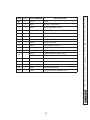
1
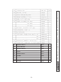
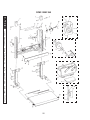
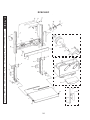
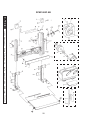
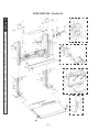
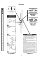
M-91-18
REV. C
JUNE 2008
MAINTENANCE
MANUAL
RCM-1250 C
RCM-1250 C AB
RCM-1600
RCM-1600 C AB
LIFT CORP.
© MAXON Lift Corp. 2008
11921 Slauson Avenue
Santa Fe Springs, CA 90607
(800) 227-4116
11921 Slauson Ave.
Santa Fe Springs, CA. 90670
LIFT CORP.
CUSTOMER SERVICE:
TELEPHONE (562) 464-0099 TOLL FREE (800) 227-4116
FAX: (888) 771-7713
NOTE: For latest version of all Manuals (and replacements), download the
Manuals from Maxon’s website at www.maxonlift.com.
WARRANTY/ RMA POLICY & PROCEDURE
LIFTGATE WARRANTY
Type of Warranty:
Full Parts and Labor
Term of Warranty:
Standard Liftgates - 2 years from ship date or 6,000 cycles
Premium Liftgates - 2 years from ship date or 10,000 cycles
This warranty shall not apply unless the product is installed, operated and maintained in accordance with MAXON Lift’s specifications as set forth in
MAXON Lift’s Installation, Operation and Maintenance manuals. This warranty does not cover normal wear, maintenance or adjustments, damage or
malfunction caused by improper handling, installation, abuse, misuse, negligence, or carelessness of operation. In addition, this warranty does not
cover equipment that has had unauthorized modifications or alterations made to the product.
MAXON agrees to replace any components which are found to be defective during the first 2 years of service, and will reimburse for labor based on
MAXON’s Liftgate Warranty Flat Rate Schedule. (Copy of the Flat Rate is available at www.maxonlift.com.)
All warranty repairs must be performed by an authorized MAXON warranty facility. For any repairs that may exceed $500, including parts and labor,
MAXON’s Technical Service Department must be notified and an “Authorization Number” obtained.
All claims for warranty must be received within 30 Days of the repair date, and include the following information:
1. Liftgate Model Number and Serial Number
2. The End User must be referenced on the claim
3. Detailed Description of Problem
4. Corrective Action Taken, and Date of Repair
5. Parts used for Repair, Including MAXON Part Number(s)
6. MAXON R.M.A. # and/or Authorization # if applicable (see below)
7. Person contacted at MAXON if applicable
8. Claim must show detailed information i.e. Labor rate and hours of work performed
Warranty claims can also be placed online at www.maxonlift.com. Online claims will be given priority processing.
All claims for warranty will be denied if paperwork has not been received or claim submitted via Maxon website for processing by MAXON’s Warranty
Department within 30 days of repair date.
All components may be subject to return for inspection, prior to the claim being processed. MAXON products may not be returned without prior written
approval from MAXON’s Technical Service Department. Returns must be accompanied by a copy of the original invoice or reference with original
invoice number and are subject to a credit deduction to cover handling charges and any necessary reconditioning costs. Unauthorized returns will be
refused and will become the responsibility of the returnee.
Any goods being returned to MAXON Lift must be pre-approved for return, and have the R.M.A. number written on the outside of the package in plain
view, and returned freight prepaid. All returns are subject to a 15% handling charge if not accompanied by a detailed packing list. Returned parts
are subject to no credit and returned back to the customer. Defective parts requested for return must be returned within 30 days of the claim date for
consideration to:
MAXON Lift Corp.
10321 Greenleaf Ave., Santa Fe Springs, CA 90670
Attn: RMA#__
MAXON’s warranty policy does not include the reimbursement for travel time, towing, vehicle rental, service calls, oil, batteries or loss of income due to
downtime. Fabrication or use of non Maxon parts, which are available from MAXON, are also not covered.
MAXON’s Flat Rate Labor Schedule takes into consideration the time required for diagnosis of a problem.
All Liftgates returned are subject to inspection and a 15% restocking fee. Any returned Liftgates or components that have been installed or not returned
in new condition will be subject to an additional reworking charge, which will be based upon the labor and material cost required to return the Liftgate or
component to new condition.
PURCHASE PART WARRANTY
Term of Warranty: 1 Year from Date of Purchase.
Type of Warranty: Part replacement only. MAXON will guarantee all returned genuine MAXON replacement parts upon receipt and inspection of parts
and original invoice.
All warranty replacements parts will be sent out via ground freight. If a rush shipment is requested, all freight charges will be billed to the requesting
party.___
TABLE OF CONTENTS
WARNINGS ........................................................................................................................... 6
SAFETY INSTRUCTIONS .................................................................................................... 6
PERIODIC MAINTENANCE.................................................................................................. 8
PERIODIC MAINTENANCE CHECKLIST ............................................................................. 8
11921 Slauson Ave. Santa Fe Springs, CA. 90670 (800) 227-4116 FAX (888) 771-7713
CHECKING HYDRAULIC FLUID .......................................................................................... 9
CHANGING HYDRAULIC FLUID .........................................................................................11
CLEAN AND LUBRICATE COLUMNS ................................................................................ 13
ADJUST DRIVE CHAINS .................................................................................................... 14
PARTS BREAKDOWN ....................................................................................................... 16
RCM-1250C......................................................................................................................... 16
RCM-1250C AB ................................................................................................................... 20
RCM-1600C......................................................................................................................... 24
RCM-1600C AB ................................................................................................................... 28
PUMP ASSEMBLY (GRAVITY DOWN) ............................................................................... 32
HYDRAULIC COMPONENTS ............................................................................................. 34
PUMP BOX ASSEMBLY ...................................................................................................... 36
CONTROL SWITCH ............................................................................................................ 37
DECALS .............................................................................................................................. 38
DRIVE CHAIN SYSTEM DIAGRAM .................................................................................... 39
HYDRAULIC SYSTEM DIAGRAM ...................................................................................... 40
ELECTRICAL SYSTEM DIAGRAM ..................................................................................... 41
TROUBLESHOOTING ........................................................................................................ 42
PLATFORM WILL NOT RAISE, MOTOR WILL NOT RUN .................................................. 42
PLATFORM WILL NOT LOWER ......................................................................................... 43
PLATFORM RAISES, BUT LEAKS DOWN ......................................................................... 44
PLATFORM RAISES, BUT WILL NOT LIFT RATED CAPACITY ........................................ 44
4
5
11921 Slauson Ave. Santa Fe Springs, CA. 90670 (800) 227-4116 FAX (888) 771-7713
THIS PAGE INTENTIONALLY LEFT BLANK
Comply with the following WARNINGS and SAFETY INSTRUCTIONS while maintaining
Liftgates. See Operation Manual for operating safety requirements.
WARNINGS
!
WARNING
• Do not stand, or allow obstructions, under the platform when lowering the Liftgate. Be sure your
feet are clear of the Liftgate.
• Keep fingers, hands, arms, legs, and feet clear of moving Liftgate parts (and platform
edges) when operating the Liftgate.
• Correctly stow platform when not in use. Extended platforms could create a hazard for
people and vehicles passing by.
11921 Slauson Ave. Santa Fe Springs, CA. 90670 (800) 227-4116 FAX (888) 771-7713
• Disconnect Liftgate power cable from battery before repairing or servicing Liftgate.
• If it is necessary to stand on the platform while maintaining the Liftgate, keep your feet and any
objects clear of the inboard edge of the platform. Your feet or objects on the platform can become
trapped between the platform and the Liftgate extension plate.
• Recommended practices for welding on steel parts are contained in the current AWS (American
Welding Society) D1.1 Structural Welding Code - Steel. Damage to Liftgate and/or vehicle, and
personal injury could result from welds that are done incorrectly.
• Recommended practices for welding on aluminum parts are contained in the current AWS
(American Welding Society) D2.1 Structural Welding Code - Aluminum. Damage to Liftgate
and/or vehicle, and personal injury could result from welds that are done incorrectly.
SAFETY INSTRUCTIONS
SAFETY INSTRUCTIONS
• Read and understand the instructions in this Maintenance Manual before performing maintenance on the Liftgate.
• Before operating the Liftgate, read and understand the operating instructions in Operation
Manual.
• Comply with all WARNING and instruction decals attached to the Liftgate.
• Keep decals clean and legible. If decals are illegible or missing, replace them. Free replacement
decals are available from Maxon Customer Service.
• Consider the safety and location of bystanders and location of nearby objects when operating the
Liftgate. Stand to one side of the platform while operating the Liftgate
• Do not allow untrained persons to operate the Liftgate.
• Wear appropriate safety equipment such as protective eyeglasses, faceshield and clothing while
performing maintenance on the Liftgate and handling the battery. Debris from drilling and contact
with battery acid may injure unprotected eyes and skin.
• Be careful working by an automotive type battery. Make sure the work area is well ventilated and
there are no flames or sparks near the battery. Never lay objects on the battery that can short the
terminals together. If battery acid gets in your eyes, immediately seek first aid. If acid gets on your
skin, immediately wash it off with soap and water.
6
• A correctly installed Liftgate operates smoothly and reasonably quiet. The only noticeable noise
during operation comes from the power unit while the platform is raised. Listen for scraping, grating and binding noises and correct the problem before continuing to operate Liftgate.
• Use only Maxon Authorized Parts for replacement parts. Provide Liftgate model and serial number information with your parts order. Order replacement parts from:
MAXON LIFT CORP. Customer Service
11921 Slauson Ave., Santa Fe Springs, CA 90670
Online: www.maxonlift.com
Express Parts Ordering: Phone (800) 227-4116 ext. 4345
Email: Ask your Customer Service representative
7
11921 Slauson Ave. Santa Fe Springs, CA. 90670 (800) 227-4116 FAX (888) 771-7713
• If an emergency situation arises (vehicle or Liftgate) while operating the Liftgate, release the control switch to stop the Liftgate.
PERIODIC MAINTENANCE
PERIODIC MAINTENANCE CHECKLIST
!
WARNING
Never operate the Liftgate if parts
are loose or missing.
Annually or 5000 Cycles (whichever occurs first)
11921 Slauson Ave. Santa Fe Springs, CA. 90670 (800) 227-4116 FAX (888) 771-7713
Visually check the entire Liftgate for excessively worn parts and broken welds, especially
the Hinge Pins. See PARTS BREAKDOWN section for replacement parts. With the Cylinder Housing Cover removed, lubricate drive chains with red grease. Also, do the Semi-annual and Quarterly Maintenance checks.
Semi-annually or 2500 Cycles (whichever occurs first)
Visually check the Platform Hinge Pins for excessive wear and broken welds. See PARTS
BREAKDOWN section for replacement parts. Also, do the Quarterly Maintenance checks.
Quarterly or 1250 Cycles (whichever occurs first)
Check the Hydraulic Fluid level in the Pump Reservoir. Refer to the CHECKING HYDRAULIC FLUID procedure in the PERIODIC MAINTENANCE section.
If Hydraulic Fluid appears contaminated, refer to the CHANGING HYDRAULIC FLUID
procedure in the PERIODIC MAINTENANCE section.
Keep track of the grade of Hydraulic Fluid in the Pump Reservoir and never mix two different grades of fluid.
Check all Hoses and Fittings for chaffing and fluid leaks. Replace if necessary.
Check electrical wiring for chaffing and make sure wiring connections are tight and free of
corrosion.
Check that all WARNING and instruction decals are in place and legible.
Check that all roll pins are in place and protrude evenly from both sides of Hinge Pin collar.
Replace roll pins if necessary.
CAUTION
Damaged cylinder seals and contaminated hydraulic fluid can result from painting the polished portion of the cylinder rod. To prevent damage, protect the
exposed polished portion of the cylinder rod while painting.
Check for rust and oily surfaces on Liftgate. If there is rust or oil on the Liftgate, clean it off.
Touch up the paint where bare metal is showing.
8
CAUTION
Keep dirt, water and other contaminants from entering the hydraulic system.
Before opening the hydraulic fluid reservoir filler cap, drain plug and hydraulic lines, clean up contaminants that can get in the openings. Also, protect the
openings from accidental contamination.
NOTE: Use correct grade of hydraulic fluid for your location.
+50 to +120 Degrees F - Grade ISO 32
Below + 70 Degrees F - Grade ISO 15 or MIL-H-5606
See TABLES 10-1 and 10-2 for recommended brands.
NOTE: If the hydraulic fluid in the reservoir is contaminated, do the CHANGING
HYDRAULIC FLUID procedure in this section.
1. Open and lower platform to ground level.
Unfasten latch and remove the pump cover
(FIG. 9-2) .
PUMP COVER
2. Remove threaded filler cap (FIG. 9-2).
Check the hydraulic fluid level in reservoir.
hydraulic fluid level should be 1” below the
top of filler hole (FIG. 9-2). If needed,
add hydraulic fluid to fill the reservoir to the
level shown in FIG. 9-2.
LATCH
REMOVING / REINSTALLING
PUMP COVER
FIG. 9-1
3. Reinstall filler cap (FIG. 9-2).
FILLER CAP
CAUTION
RESERVOIR
Pump Cover must be correctly secured
to prevent it from becoming a hazard.
To secure Pump Cover, fasten the rubber latch on the Pump Box to the receiver on the Pump Box Cover.
4. Reinstall the pump cover and fasten
latch (FIG. 9-2).
1”
CHECKING FLUID LEVEL
FIG. 9-2
9
11921 Slauson Ave. Santa Fe Springs, CA. 90670 (800) 227-4116 FAX (888) 771-7713
CHECKING HYDRAULIC FLUID
PERIODIC MAINTENANCE
CHECKING HYDRAULIC FLUID - Continued
ISO 32 HYDRAULIC OIL
RECOMMENDED
BRANDS
PART NUMBER
11921 Slauson Ave. Santa Fe Springs, CA. 90670 (800) 227-4116 FAX (888) 771-7713
AMSOIL
AWH-05
CHEVRON
HIPERSYN 32
KENDALL
GOLDEN MV
SHELL
TELLUS T-32
EXXON
UNIVIS N-32
MOBIL
DTE-13M, DTE-24,
HYDRAULIC OIL-13
TABLE 10-1
ISO 15 OR MIL-H-5606 HYDRAULIC OIL
RECOMMENDED
BRANDS
PART NUMBER
AMSOIL
AWF-05
CHEVRON
FLUID A, AW-MV-15
KENDALL
GLACIAL BLU
SHELL
TELLUS T-15
EXXON
UNIVIS HVI-13
MOBIL
DTE-11M
ROSEMEAD
THS FLUID 17111
TABLE 10-2
10
CAUTION
Keep dirt, water and other contaminants from entering the hydraulic system.
Before opening the hydraulic fluid reservoir filler cap, drain plug and hydraulic lines, clean up contaminants that can get in the openings. Also, protect the
openings from accidental contamination.
NOTE: Use correct grade of hydraulic fluid for your location.
+50 to +120 Degrees F - Grade ISO 32
Below + 70 Degrees F - Grade ISO 15 or MIL-H-5606
See TABLES 10-1 and 10-2 for recommended brands.
FLOW CONTROL
VALVE
1. Open and lower Platform to ground
level. Remove cover from cylinder
housing. Disconnect pressure hose
from the flow control valve on the cylinder (FIG. 11-1).
CYLINDER
HYDRAULIC HOSE
(PRESSURE LINE)
CONNECTING / DISCONNECTING
PRESSURE LINE
FIG. 11-1
2. Unfasten latch and remove the pump cover
(FIG. 11-2) .
PUMP COVER
NOTE: To prevent spills, drain used
hydraulic fluid into an empty 5
gallon bucket. Hold hydraulic
hose in container until fluid stops
flowing. If needed, get a helper.
3. Place disconnected end of hydraulic
hose in an empty 5 gallon bucket. Set
control switch to RAISE position until the
hydraulic system starts to make cavitating sounds. Release the control switch.
When fluid stops flowing from hydraulic
hose, re-connect hose to RAISE port on
the cylinder (FIG. 11-1). Reinstall cover
on cylinder Housing (FIG. 11-1). Move
5 gallon bucket from work area and dispose fluid correctly.
LATCH
REMOVING / REINSTALLING
PUMP COVER
FIG. 11-2
11
11921 Slauson Ave. Santa Fe Springs, CA. 90670 (800) 227-4116 FAX (888) 771-7713
CHANGING HYDRAULIC FLUID
PERIODIC MAINTENANCE
CHECKING HYDRAULIC FLUID - Continued
4. Remove threaded Filler Cap (FIG. 12-1).
Fill the Reservoir with correct Hydraulic
Fluid to the level shown in FIG. 12-1.
FILLER CAP
RESERVOIR
1”
11921 Slauson Ave. Santa Fe Springs, CA. 90670 (800) 227-4116 FAX (888) 771-7713
5. Reinstall Filler Cap (FIG. 12-1).
CHECKING FLUID LEVEL
FIG. 12-1
CAUTION
Pump Cover must be correctly secured
to prevent it from becoming a hazard.
To secure Pump Cover, fasten the rubber latch on the Pump Box to the receiver on the Pump Box Cover.
6. Reinstall the Pump Cover and fasten
latch (FIG. 10-2).
12
CAUTION
Do not apply heavy grease to the Lift Column
CLEAN & LUBRICATE
1. Thoroughly pressure wash (or steam clean)
inside surfaces of both Lift columns (FIG.
13-1) to remove oil, grease, and debris.
CAUTION
Do not store can of lubricant on truck
2. Lubricate inside each of the two Lift columns (FIG. 13-1) with light machine
oil, white grease, silicon spray, or teflon
spray.
FIG. 13-1
3. Repeat washing procedure if there is any
build up of solid lubricant. Re-apply recommended lubricants as required.
13
11921 Slauson Ave. Santa Fe Springs, CA. 90670 (800) 227-4116 FAX (888) 771-7713
CLEAN AND LUBRICATE COLUMNS
PERIODIC MAINTENANCE
ADJUST DRIVE CHAINS
NOTE: Vehicle body must be empty
(unloaded) before performing
the following adjustment.
1. Adjust drive chains as follows.
ADJUSTING
RODS
ADJUSTING
NUTS
CYLINDER
LOCK NUTS
11921 Slauson Ave. Santa Fe Springs, CA. 90670 (800) 227-4116 FAX (888) 771-7713
2. Remove cover from Cylinder Housing. Loosen the lock nut on each chain
adjusting rod (FIG. 14-1). Then lower
Platform to ground level.
ADJUSTING DRIVE CHAIN
FIG. 14-1
3. Turn each chain adjusting nut (FIG.
14-1) an equal amount of clockwise
turns (alternate from chain to chain) until
hydraulic cylinder is fully compressed.
Then tighten the lock nut (FIG. 14-1)
on each chain.
4. If either of the 2 chain rods are too
long, cut off the excess as shown in
FIG. 14-1.
14
15
11921 Slauson Ave. Santa Fe Springs, CA. 90670 (800) 227-4116 FAX (888) 771-7713
THIS PAGE INTENTIONALLY LEFT BLANK
PARTS BREAKDOWN
RCM-1250C
11921 Slauson Ave. Santa Fe Springs, CA. 90670 (800) 227-4116 FAX (888) 771-7713
16
252983-01
SPRING
17
252983-03
2
252460
1
252999
2
NOT USED
NOT USED
2
11921 Slauson Ave. Santa Fe Springs, CA. 90670 (800) 227-4116 FAX (888) 771-7713
252983-02
RCM-1250C - Continued
11921 Slauson Ave. Santa Fe Springs, CA. 90670 (800) 227-4116 FAX (888) 771-7713
18
BRACKET, STOP, LH
252461
1
38
LOCKING BRACKET
252467
1
39
BRACKET, STOP, RH
252466
1
40
HANDLE
252473
1
41
BRACKET, SWITCH
251711
1
42
CHANNEL
251028
1
43
PLATFORM STOP
252464
2
44
BRACKET
250265
2
45
RETAINER
250266
1
19
11921 Slauson Ave. Santa Fe Springs, CA. 90670 (800) 227-4116 FAX (888) 771-7713
37
RCM-1250C AB
11921 Slauson Ave. Santa Fe Springs, CA. 90670 (800) 227-4116 FAX (888) 771-7713
20
252983-01
252983-03
SPRING
252460
252999
21
1
2
NOT USED
NOT USED
2
11921 Slauson Ave. Santa Fe Springs, CA. 90670 (800) 227-4116 FAX (888) 771-7713
252983-02
RCM-1250C AB - Continued
11921 Slauson Ave. Santa Fe Springs, CA. 90670 (800) 227-4116 FAX (888) 771-7713
22
BRACKET, STOP, LH
252461
1
43
LOCKING BRACKET
252467
1
44
BRACKET, STOP, RH
252466
1
45
HANDLE
252473
1
46
BRACKET, SWITCH
251711
1
47
CHANNEL
251028
1
48
PLATFORM STOP
252464
2
49
BRACKET
250265
2
50
RETAINER
250266
1
23
11921 Slauson Ave. Santa Fe Springs, CA. 90670 (800) 227-4116 FAX (888) 771-7713
42
RCM-1600C
11921 Slauson Ave. Santa Fe Springs, CA. 90670 (800) 227-4116 FAX (888) 771-7713
24
252984-01
252984-03
SPRING
25
252460
1
252999
2
NOT USED
NOT USED
2
11921 Slauson Ave. Santa Fe Springs, CA. 90670 (800) 227-4116 FAX (888) 771-7713
252984-02
RCM-1600C - Continued
11921 Slauson Ave. Santa Fe Springs, CA. 90670 (800) 227-4116 FAX (888) 771-7713
26
BRACKET, STOP, LH
252461
1
38
LOCKING BRACKET
252467
1
39
BRACKET, STOP, RH
252466
1
40
HANDLE
252473
1
41
BRACKET, SWITCH
251711
1
42
CHANNEL
251028
1
43
PLATFORM STOP
252464
2
44
BRACKET
250265
2
45
RETAINER
250266
1
27
11921 Slauson Ave. Santa Fe Springs, CA. 90670 (800) 227-4116 FAX (888) 771-7713
37
RCM-1600C AB
11921 Slauson Ave. Santa Fe Springs, CA. 90670 (800) 227-4116 FAX (888) 771-7713
28
252984-01
252984-03
SPRING
29
252460
1
252999
2
NOT USED
NOT USED
2
11921 Slauson Ave. Santa Fe Springs, CA. 90670 (800) 227-4116 FAX (888) 771-7713
252984-02
RCM-1600C AB - Continued
11921 Slauson Ave. Santa Fe Springs, CA. 90670 (800) 227-4116 FAX (888) 771-7713
30
BRACKET, STOP, LH
252461
1
43
LOCKING BRACKET
252467
1
44
BRACKET, STOP, RH
252466
1
45
HANDLE
252473
1
46
BRACKET, SWITCH
251711
1
47
CHANNEL
251028
1
48
PLATFORM STOP
252464
2
49
BRACKET
250265
2
50
RETAINER
250266
1
31
11921 Slauson Ave. Santa Fe Springs, CA. 90670 (800) 227-4116 FAX (888) 771-7713
42
PUMP ASSEMBLY (GRAVITY DOWN)
5 (KIT)
SOCKET HEAD
CAPSCREW
RETAINER
11921 Slauson Ave. Santa Fe Springs, CA. 90670 (800) 227-4116 FAX (888) 771-7713
SPRING
STEEL
BALL
6 (KIT)
VALVE
CAP
SPRING
2, 2A
SPRING
GUIDE
1
O-RING
3
ADJUSTING
SCREW
STEEL
BALL
4
13
14
12
7
11
10
9
8
15
32
QTY.
REF
1
250100
PUMP
1
1
229272
MOTOR, 12 VOLTS DC
2
1
253353
VALVE, SOLENOID 2-WAY
1
226594
O-RING KIT, 2-WAY VALVE (NOT SHOWN)
3
1
REF
THERMAL SWITCH
4
1
260261
OIL SEAL
5
1
251885
CHECK VALVE KIT
6
1
260229
RELIEF VALVE KIT
7
1
229193
FILLER/BREATHER CAP
8
1
251882
RESERVOIR, 3 QT.
9
1
260250
INLET FILTER
10
1
251881
PUMP ASSEMBLY (CAST IRON)
290001
PUMP ASSEMBLY (3-PIECE)
11
1
251884
O-RING
12
1
260236
DRIVEPLATE ASSEMBLY, 5”
13
1
262966
BUS BAR
14
1
262939
STARTER SOLENOID
15
4
229202
CAP SCREW, HEX WASHER HEAD
2A
PART NUMBER
DESCRIPTION
33
11921 Slauson Ave. Santa Fe Springs, CA. 90670 (800) 227-4116 FAX (888) 771-7713
ITEM
HYDRAULIC COMPONENTS
6
3
4
2
1
5
7
8
9
10
PUMP (REF)
11921 Slauson Ave. Santa Fe Springs, CA. 90670 (800) 227-4116 FAX (888) 771-7713
11
34
QTY.
PART NO.
DESCRIPTION
1
1
202141
ELBOW BRASS, 1/4” X 1/8”
2
1
224370-11
PLASTIC HOSE, 87” LG.
3
1
251739
VALVE, FLOW CONTROL 2 GPM
4
1
228151
STRAIGHT SWIVEL 3/8-18 F-M
5
1
226948-18
HOSE, 3/8” X 47-1/2” LG
6
1
252002
CYLINDER, 2” DIA. X 28” STROKE
7
1
228950
ELBOW, 3/8F-3/8F
8
1
030304
NIPPLE PIPE, 3/8” X 2-1/2”
9
1
202406
ELBOW BRASS, 1/4” X 1/4”
10
1
800183
BUSHING, 3/8” X 1/4”
11
1
906714-01
ADAPTER. 3/8”F
35
11921 Slauson Ave. Santa Fe Springs, CA. 90670 (800) 227-4116 FAX (888) 771-7713
ITEM
PUMP BOX ASSEMBLY
11921 Slauson Ave. Santa Fe Springs, CA. 90670 (800) 227-4116 FAX (888) 771-7713
3 (CATCH)
1
REFER TO
PUMP ASSEMBLY
3 (LATCH)
2
ITEM
QTY.
PART NO.
DESCRIPTION
REF
1
251741
PUMP BOX ASSEMBLY
1
1
260108
PUMP BOX COVER
2
1
260109
PUMP BOX
3
1
215139
CATCH AND FASTENER (WITH LATCH)
4
2
207645
POP RIVETS, 3/16” X 5/8” LG.
36
SWITCH MOUNTING
BRACKET (REF)
1
1A
2
(2 PLACES)
UP & DOWN DECAL
(REF)
CHANNEL
(REF)
ITEM
QTY.
PART NO.
1
1
250916
ELECTRICAL HARNESS & SWITCH ASSEMBLY
1
905206
SWITCH SEAL BOOT
2
030458
SCREW, TAPPING, #10 X 1/2” LG.
1A
2
DESCRIPTION
37
11921 Slauson Ave. Santa Fe Springs, CA. 90670 (800) 227-4116 FAX (888) 771-7713
CONTROL SWITCH
DECALS
CONTROL
SWITCH DECAL
P/N 250993
11921 Slauson Ave. Santa Fe Springs, CA. 90670 (800) 227-4116 FAX (888) 771-7713
CAPACITY DECAL
(RCM-1600 ONLY)
P/N 224751
CAPACITY DECAL
(RCM-1250 ONLY)
P/N 226006
WARNING DECAL
P/N 264081
INSTRUCTION DECAL
P/N 252899
38
If the drive chains or related parts are removed,
route the chains as shown in FIG. 39-1. Refer
to the PARTS BREAKDOWN section for the correct parts. The illustration also shows the motion
of the hydraulic cylinder, sheaves (pulleys), and
drive chains while the Platform is being raised.
DRIVE
CHAINS
SHEAVE
CYLINDER
DRIVE CHAIN ROUTING & MOTION
FOR RAISING PLATFORM
FIG. 39-1
39
11921 Slauson Ave. Santa Fe Springs, CA. 90670 (800) 227-4116 FAX (888) 771-7713
DRIVE CHAIN SYSTEM DIAGRAM
HYDRAULIC SYSTEM DIAGRAM
HYDRAULIC
CYLINDER
11921 Slauson Ave. Santa Fe Springs, CA. 90670 (800) 227-4116 FAX (888) 771-7713
2 GPM FLOW
CONTROL VALVE
AUX. TANK PORT
(PLUGGED)
VENT
PORT
PRESSURE
PORT
“A” VALVE
CHECK
VALVE
PRESSURE RELIEF
VALVE (SET AT
3250 PSI)
HAND
PUMP PORT
(PLUGGED)
PUMP
MOTOR
(REF)
FILTER
40
HAND
PUMP PORT
(PLUGGED)
CONTROL
SWITCH
WHITE
GREEN
BLACK
CABLE ASSY
STARTER
SOLENOID
SOLENOID,
VALVE “A”
BLACK
MOTOR
CABLE WITH
200 AMP FUSE
41
BATTERY
11921 Slauson Ave. Santa Fe Springs, CA. 90670 (800) 227-4116 FAX (888) 771-7713
ELECTRICAL SYSTEM DIAGRAM
TROUBLESHOOTING
PLATFORM WILL NOT RAISE, MOTOR WILL NOT RUN
1.
2.
11921 Slauson Ave. Santa Fe Springs, CA. 90670 (800) 227-4116 FAX (888) 771-7713
3.
42
11921 Slauson Ave. Santa Fe Springs, CA. 90670 (800) 227-4116 FAX (888) 771-7713
PLATFORM WILL NOT LOWER
43
TROUBLESHOOTING
PLATFORM RAISES, BUT LEAKS DOWN
11921 Slauson Ave. Santa Fe Springs, CA. 90670 (800) 227-4116 FAX (888) 771-7713
PLATFORM RAISES, BUT WILL NOT LIFT RATED CAPACITY
44