1
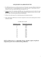
Calibration, Maintenance & Troubleshooting Tips For YSI 6-Series Sondes & Sensors
Contents
Calibration Work Sheet
i
Conductivity
1
pH
2
ORP
3
Dissolved Oxygen - Rapid Pulse 6562
4
Dissolved Oxygen - ROX 6150
6
Turbidity
8
Optimizing Turbidity Measurements in Low-Turbidity Environments
10
Chlorophyll
14
Troubleshooting Conductivity & Temperature
16
pH
17
Dissolved Oxygen - Rapid Pulse 6562
19
Dissolved Oxygen - ROX 6150
21
Depth
23
Turbidity
24
Maintenance Field Cable Servicing Procedure
26
Operation Unattended Monitoring – DO Measurements
28
Discrete Sampling – DO Measurements
30
Comparing ROX & Rapid Pulse DO Sensors
31
EcoWatch Page Width Expansion Procedure
35
CALIBRATION WORK SHEET
Date of Calibration: ___________________
Technician: ___________________________
RP DO membrane changed?
Y
RP DO membrane o-ring changed? Y
Turbidity wiper changed? Y
ROX DO wiper changed? Y
BGA-PC wiper changed? Y
N
N
N
N
N
Sonde ID: ________________________
Note: Wait 3 to 6 hours before calibrating for unattended
deployments; run in Discrete mode for 10 minutes to accelerate
burn in. (Rapid Pulse DO Only)
Chlorophyll wiper changed? Y
BGA-PE wiper changed?
Y
Rhodamine wiper changed? Y
N
N
N
Note: If parking problems occur with optical probes having a serial number 07L (Dec 07) or older, be sure the firmware is
3.06 or later. Parking issues with optical probes having a serial number prior to 07L may be related to a dirty wiper body or
pad.
Record sonde battery voltage: _______________ (if applicable)
Record Calibration Values
Standard
Pre Cal / Post Cal
Record the following diagnostic numbers after calibration.
6560 Conductivity cell constant ____________ Range 5.0 + .45
Temperature ________
Integrated conductivity cell constant_________ Range 5.0 ± .70
Conductivity ________
pH mv Buffer 7
____________ Range
pH 7
________
pH mv Buffer 4
____________
Range +180 + 50 mv*
pH 4
________
____/____
pH mv Buffer 10
____________
Range -180 + 50 mv *
pH 10
________
____/___
ORP
________
____/___
Turbidity
________
____/____
Turbidity
________
____/____
0 + 50 mv
*Note: Millivolt span between pH 4 and 7 should be ≈ 165 to 180 mv
Millivolt span between pH 7 and 10 should be ≈ 165 to 180 mv
25 to 75
____Sonde
____/____
____/____
DO charge (RP only)
____________
Range
DO gain
____________
Range 0.7 to 1.4
Turbidity 0.5________
____/____
ODO gain
____________
Range 0.85 to 1.15
Chlorophyll ________
____/____
Chlorophyll ________
____/____
Turbidity standard used in calibration _______________________
DO RP
________
____/____
Manufacturer and part number _______________________________
DO ROX
________
____/____
BGA PE/PC ________
____/____
Barometric Pressure: _________________mmHg
BGA PE/PC ________
DO % Calculated – (BARO mmHg divided by 7.6) = % saturation
Rhodamine
____/____
________
____/____
Example: 760 ÷ 7.6 = 100.0%
Depth Calibration - If zero was entered, record barometric pressure at time of calibration _____________mmHg
Depth Calibration - If offset depth was entered, record value ____________ meters/feet and pressure ____________ mmHg
Depth Calibration (Vented) – Acceptable calibration constant: 0.0 psig ± 0.15 ____________________
Notes:
i
CONDUCTIVITY CALIBRATION TIPS BEFORE YOU BEGIN: Verify the accuracy of your temperature probe with a traceable thermometer or
other temperature reference. Temperature compensation is used in every sonde measurement so its
accuracy should be verified and recorded each time the sonde is calibrated.
1. Never calibrate with conductivity standards that are less than 1.0 ms/cm. You are setting the slope on
a linear device so a good strong conductivity signal will give you the best performance. Use 1.0
ms/cm for fresh water, 10 ms/cm for brackish to estuarine, and 50 ms/cm for salt water.
3. Pre-rinse the cal cup and sensors three times with a small amount of the calibration standard or rinse
standard and discard.
4. Insure that the conductivity sensor is completely submerged in standard. The vent hole in the side of
the 6560 probe must be under the solution and sondes with integrated conductivity sensors (600R,
600QS, 600LS, and 600OMS) must also be completely submerged. It is important not to have
trapped bubbles in the cells. Gently shake the sonde to help dislodge any air bubbles that may be
trapped in the conductivity sensor.
5. If the sonde reports “Out of Range” after the calibration, investigate the cause! Never override a
calibration error message without knowing the reason. Typical causes for this error message are
incorrect entries (entering 1000 us/cm instead of 1.0 ms/cm), low solution level, air bubbles in the
probes cell, calibrating in conductivity instead of sp/cond, and/or bad standard.
6. When the calibration has been accepted, check the conductivity cell constant which is located in the
sonde’s “Advanced Menu” under “Cal Constants”. The acceptable range for the 6560 probe is 5 ±
0.45. Numbers outside of this range indicate a problem in the calibration process or with the
standard that was used.
Note: integral conductivity sensors have a higher positive limit. Use the tolerance 0.45 to 0.70 for
QA on 600R, QS, LS, and 600OMS sondes.
NOTICE: The full operating range of the YSI conductivity sensor circuit is 4.0 to 6.0. See the 6Series manual for additional information. This means that if you exceed 4.0 or 6.0, you will get an
“OUT OF RANGE” error message which you should never accept. Therefore, for example, never
accept a Cell Constant of 5.9, when the historical Cell Constant has always been around 5.10 to 5.20.
Investigate why you have drastically changed the historical Cell Constant and make attempts to get
the historical Cell Constant back.
CAUTION: The historical Cell Constant may change if changes are done to the probe, for example,
applying anti-fouling paint to the inner holes where the Pure Nickel Electrodes are located will
change your Cell Constant. But, once painted and a new Cell Constant has been established, you
should now be observing near that value for future calibrations.
1
pH CALIBRATION TIPS 1. Go to the sonde’s Report Menu and enable the pH mv output. This will allow the sonde to display
the millivolt output from the probe as well as the pH units during the calibration process.
2. Recondition the probe if a slow response in the field has been reported or if it takes more than 90
seconds to stabilize in pH buffer. The procedure to do this can be found in your manual under the
Sonde Care and Maintenance section.
3. In most cases, a two-point calibration is all that is required. Bracket the expected in-situ pH values;
use the three-point calibration only if the in-situ pH value is unknown. Start all calibrations in buffer
7.
4. Calibrate the pH. Rinse the sensor and cal cup with a small amount of pH buffer. Fill the cup so that
the pH probe tip and the sonde’s temperature probe are submerged in buffer. Enter the pH value
based on the solution temperature. Record the pH millivolts for each calibration point. The
acceptable millivolt output for each buffer is shown below.
Buffer 4
Buffer 7
Buffer 10
= +180
=
0
= -180
± 50 mv
± 50 mv
± 50 mv
5. After recording the pH millivolts for the calibration points, you must determine the slope of the
sensor. This is done by determining the difference between the two calibration points that were used.
For example, if we recorded a +3 mv for buffer 7 and a -177 for the buffer 10, then the slope would
be 180. The acceptable range for the slope is 165 to 180. Once the slope drops below 160, the
sensor should be taken out of service.
Warning: Do not use a probe that has given any “Calibration Error” or “Out of Range” warnings.
6. Note: When calibrating any of the flat glass pH sensors you may experience jumpy pH readings in
conditions where static electricity is present. Calibrating in glassware is recommended in these
situations. Also, try to keep your body at least 1 meter from the sonde to prevent the sensor from
detecting your body’s capacitance.
NOTICE: The Calibration Work Sheet and information above is working with a pH probe that is still in
“quality” working order. The pH mv would have to exceed around 70 mv before it would get an out of
“OUT OF RANGE” error message. Therefore, the ± 50 mv is the range at which you should start giving
close attention as to how the probe should be used. Spot sampling would not be as critical as the mv can
be reviewed daily, but a long term deployment should be questioned if to use a probe with an offset at or
greater than 50 mv.
The same would apply to the 165 - 180 slope, we know that a probe can get down to a slope of nearly
155 mv before an error message would occur. But a probe with a slope of 162 should not be used for
any long term deployments.
2
ORP/REDOX CALIBRATION TIPS 1. The ORP and pH sensors are combined on all current YSI sondes. You must calibrate the pH sensor
first and insure that it is working properly before you calibrate the ORP. If the pH probe will not
calibrate for any reason, then the ORP has been disabled as well.
2. Warning: On the 6569 combination pH/ORP sensor, the guard has been removed to allow the wiper
on the 6600V2 sonde to clean the junction and the glass bulbs. Handle this sensor with care so that
the glass bulb is not broken during calibration and handling.
3. Reference the sonde manual for reconditioning tips and cleaning instructions.
4. When calibrating the ORP sensor, the sonde’s temperature sensor must be submerged in the Zobell
calibration solution.
CALIBRATION CHART
Temperature Celsius
-5
0
5
10
15
20
25
30
35
40
45
50
Zobell Solution Value, MV
270.0
263.5
257.0
250.5
244.0
237.5
231.0
224.5
218.0
211.5
205.0
198.5
NOTE: All ISE sensors, i.e. Ammonium, Nitrate, Chloride, requires the pH and
temperature probe to be in solution during calibration.
3
DISSOLVED OXYGEN CALIBRATION TIPS UNATTENDED & SAMPLING DO SENSOR PREPARATION
1. Inspect the DO probe anodes; recondition using the 6035 reconditioning kit if they are not bright and
shiny.
2. Install a new membrane, making sure that it is tightly stretched and wrinkle free.
Warning: Replace the probe o-ring if it is loose or stretched out. If you remove the DO probe from
the sonde, be sure to inspect the probe port and connectors for moisture. Remove any moisture
droplets from the connector and thread areas. Verify that the probe is clean and dry then apply a
small amount of synthetic grease to the o-ring before it is reassembled.
Note: DO membranes will be slightly unstable during the first 3 to 6 hours after they are installed; it
is strongly recommended that the final calibration of a DO sensor being used in “Unattended”
studies takes place after this time period.
3. Go to the sonde’s Report Menu and enable the “DO Charge”. Now go to the Run Menu and start the
sonde in the “Discrete Run” mode at a four-second rate. Allow the sonde to run (burn-in) for 15
minutes. Record the DO charge after about 5 minutes. The charge number must be between 25 and
75.
4. After the burn-in is complete, go to the sonde’s Advanced Menu and confirm that the RS-232 Auto
Sleep function is enabled. If the sonde is to be connected to an SDI-12 data logger, then the SDI-12
Auto Sleep must be enabled as well. Wait 60 seconds before proceeding to Step 5.
5. Start the probe in the “Discrete Run” mode at a four-second rate and record the first 10 DO %
numbers on paper. The numbers must start at a high number and drop with each four second sample.
Example: 110, 105, 102, 101.5, 101.1, 101.0, 100.8, 100.4, 100.3, 100.1
It does not matter if the numbers do not reach 100%; it is only important that they have the same
high to low trend. If you have a probe that starts at a low number and steadily climbs upwards, then
the sensor has a problem and it must not be used.
Note: Initial power up can make the first two DO % samples read low; the first two samples can be
disregarded.
(continued)
4
6. The probe is now ready to be calibrated. Set the Auto Sleep RS-232 for the intended application:
ON for UNATTENDED STUDIES and OFF for SAMPLING MEASUREMENTS. Set the sonde
into the calibration cup with approximately 1/8 inch of water. Do not engage the threads, and do not
allow water to contact the membrane. You may also use the wet-towel method. The sonde must now
sit in this saturated environment for at least 10 minutes before the DO calibration can begin.
Warning: The sonde must be idle and not in the “Run” mode for 5 minutes prior to starting the DO
calibration.
Calibrate the sonde in DO %; be sure to enter your local barometric pressure in mmHg. In
Unattended mode (RS-232 Auto-Sleep ON) the DO probe will be calibrated automatically once the
barometric pressure is entered and the warm-up time counter counts down to zero. For Discrete or
Sampling, press the Enter key when the DO readings are stable. Wait at least 3 minutes after you
enter the barometric pressure before you press the Enter key again to calibrate for Discrete/Sampling
DO measurements.
7. When the calibration is completed, go to the sonde’s Advanced Menu and then to the “Cal
Constants” and record the “DO Gain”. The gain should be 1.0 with a range of 0.7 to 1.4. The probe
is now calibrated and ready to prepare for the study. As with the other parameters, any warning
messages displayed by the sonde during the calibration are a cause for concern and must be
investigated before collecting field data with the sonde.
Warning: Avoid having the DO probe membrane contact the calibration cup or sensor guard during
transfers. Keep the DO probe in sight when removing or installing the sensor guard and cal cup.
5
ROX™ OPTICAL DISSOLVED OXYGEN CALIBRATION TIPS ROX FACTS
•
•
•
•
•
•
•
The ROX Optical Dissolved Oxygen sensor does not require any special sonde setup or burn-in.
Calibration data is stored in the ROX so it can be calibrated in one sonde and then used in another
without recalibrating the probe in the new sonde.
Calibration data is automatically transferred to the host sonde as soon as the sonde powers up the
ROX sensor.
The ROX has excellent long term stability and will achieve ± 1% accuracy when calibrated in a
(temperature-stable) saturated water or saturated air environment.
Field DO calibrations should be avoided!
Remove the wiper when the sensor is going to be exposed to sodium sulfite (zero DO test) or
Formazin-based turbidity standards.
The ROX sensor must remain hydrated at all times! See Appendix M in the 6-Series manual for
additional information.
CALIBRATION METHOD – ONE-POINT “SATURATED AIR”
1. Dry the temperature sensor and the ROX membrane to remove any water droplets.
2. Put 1 inch of water in the calibration cup and thread onto the endcap ½ thread.
Do not fully thread the calibration cup onto the endcap!
3. Allow the sonde to sit in the calibration cup for 15 minutes to ensure that the air is 100%
saturated and that the temperature is stable.
4. Select ODO% and enter the barometric pressure in mmHg (inches x 25.4) and press Enter. The
sonde will do a 4 second count down and then say “Press Enter when the readings are stable”.
Wait at least 30 seconds before you press the Enter button.
Note: the sonde will only read 100% saturation if the barometric pressure is 760 mmHg. To
determine the actual DO in %, divide the barometer reading by 760 and then multiply that
number by 100.
Example: 750 ÷ 760 = 0.9868 x100 = 98.68%
Check the ODO Gain in the Advanced Menu. An acceptable range is 0.85 to 1.15, NOTE:
Maximum range before getting error message is 1 ± .25.
CALIBRATION METHOD – ONE-POINT “SATURATED WATER”
1. Using a medium-size aquarium air pump and air stone, sparge a five-gallon bucket of tap water
for 1 hour.
2. Place the assembled sonde in the bucket and allow the sonde to equilibrate to the water
temperature for 5 minutes.
3. Select ODO% and enter the barometric pressure in mmHg (inches x 25.4) and press Enter. The
sonde will do a four-second countdown and then say “Press Enter when the readings are
stable”. Wait at least 30 seconds before you press the Enter button.
(continued)
6
Note: the sonde will only read 100% saturation if the barometric pressure is 760 mmHg. To
determine the actual DO in %, divide the barometer reading by 760 and then multiply that
number by 100.
Example: 750 ÷ 760 = 0.9868 x100 = 98.68%
Check the ODO Gain in the Advanced Menu. An acceptable range is 0.85 to 1.15.
CALIBRATION METHOD – TWO-POINT “AIR or WATER”
Note: YSI does not recommend the two-point calibration unless (A) you are certain that the sensor does
not meet your accuracy requirements at low DO values and (B) you are operating under conditions
where you are certain you can generate a medium that is truly free of oxygen!
1. REMOVE THE ROX WIPER! Sodium sulfite will be absorbed into the pad and will be
applied to the ROX membrane each time the wiper is activated. This will contaminate the ROX
membrane and create a problem with the second point of the calibration.
2. Mix 2 grams of sodium sulfite to 1000 milliliters of tap water 2 hours prior to use and keep it
in a sealed bottle. Rapidly transfer this mixture into the sonde’s calibration cup and fill to
overflow. Install the sonde and completely seal the cup to prevent diffusion of air into the
vessel.
3. o calibrate, select ODO % Two-Point.
4. The first entry for the two-point calibration will be in mg/L! Wait at least 10 to 12 minutes for
the solution to re-equilibrate and then type 0 and press Enter. Remove the sonde from the
sodium sulfite and thoroughly rinse all exposed surfaces, especially the ROX membrane, with
tap water. Rinse at least 4 times if using a filled calibration cup.
5. Enter the barometric pressure in mmHg for the second calibration point and press the Enter key
when the reading is stable. Remember that you must wait 15 minutes for the air to saturate in
the cal cup or 5 minutes if the sonde is in saturated water.
6. Verify that the ODO Gain found in the Advanced Cal Constants menu is between 0.85 and
1.15.
Note: If you believe that you have calibrated a ROX probe in error (especially the zero), then you can
return the probe back to its original factory calibration by using the “uncal” command. With a PC, type
the word ‘uncal” instead of the barometric pressure and press Enter. If using a 650, at the point where
you would type in the barometer, press the Esc and Enter keys simultaneously.
7
TURBIDITY 6136 PROBE CALIBRATION TIPS
Note: The calibration of all YSI turbidity sensors must be done with either YSI distributed standards,
Hach StablCal, diluted Hach 4000 NTU Formazin, or standards that have been prepared according to the
instructions in Standard Methods (Section 2130B). Standards from other vendors are NOT approved,
and their use will likely result in a bad calibration and incorrect field readings. Please refer to the
turbidity calibration section of your manual for more information.
BEFORE YOU BEGIN: Upgrade your sonde firmware to version 3.08 at www.ysi.com
SET UP & OPERATION
•
•
•
•
•
•
•
Confirm that the wiper is parking correctly and reverses direction.
Clean the optics of any fouling, fingerprints, etc.
Low-turbidity water measurement accuracy can be improved by increasing the probe’s sampling
frequency. See the “Optimizing Turbidity Performance” section for specific instructions.
Make sure that the back edges of all white turbidity wipers are painted black to eliminate any
stray light reflection.
Calibrate 6600 in the long calibration cup (9.5 inch length) or use a clean sensor guard.
Calibrate 6820 and 6920 (Single Optical Port) in the calibration cup.
Calibrate 6820V2-2, 6920V2-2 and 600OMS sondes in the calibration cup but repeat the zero
with the guard installed. See Optimizing Turbidity Measurements section for more details.
CALIBRATION PROCESS
1. The first step is to confirm that the turbidity probe is functioning properly. Confirm that the
wiper parks correctly. It should be positioned at approximately 180° opposite the optics. The
wiper must reverse direction during the wipe cycle. The output of the probe must increase when
you place your finger in front of the optics. If the wiper does not park correctly or reverse
direction, then make sure that the underside of the wiper is clean and free of mud, sediment, or
other fouling. Replace the wiper or pad with a spare if needed. If the probe does not show an
increase in output or the wiper does not park correctly, then you must stop the calibration and
determine the cause of the problem.
2. Calibrating turbidity is best done in a lab environment; calibrations in the field can result in
errors. It is better to post-calibrate a sonde back in the lab than to attempt the calibration of an
optical probe in the field, especially if you are working out of a small boat or in less than clean
conditions.
3. Never use plastic or glass containers for your calibration unless the sensor guard is installed on
the sonde. Use of the supplied calibration/storage cup with its black endcap is strongly
recommended.
(continued)
8
4. Always ensure that the submerged parts of the sonde and wipers are clean before beginning any
turbidity calibration. Remove any brush wipers and replace with a clean, standard (no brush)
wiper. Sediment or other contaminants will compromise the standard if not removed prior to
calibration. Make especially sure the optics are clean, no fingerprints!
5. Always start with the zero (0) NTU standard first. Pour the 0 NTU cal standard into the
calibration cup -- pour down the side so you do not aerate the sample. Secure the sonde into the
calibration cup. Verify that there are no air bubbles on the probe face, run the wiper at least once,
and wait out the probe’s sampling period before accepting the first calibration point.
6. Older YSI 6600 calibration cups (~ 7.5″ length) are slightly shorter than the sonde’s sensor
guard. This shorter cup minimizes the use of standards when calibrating the sensors. In
deployments where low turbidity readings are expected, the sonde should be spaced off the
calibration cup 2.5 inches. The sonde will report a slightly negative reading (typically less than
-1.0 NTU) when calibrated with the sonde resting on the calibration cup.
Note: A longer cal cup is available (p/n 116275) which eliminates the need for the two-inch
spacing. The longer calibration cup is now shipped with all new 6600 sondes.
7. Calibrate the second point, typically 126 NTU. Again, wipe the probe at least once before
pressing the enter button.
Note: Never override a calibration error message without understanding the cause of the
problem. Error messages indicate that a problem exists that could result in incorrect field
readings.
Note: For the YSI prepared AMCO-AEPA standards, the value entered during the calibration protocol
is DIFFERENT depending on which YSI turbidity sensor (6026 or 6136) is being calibrated. The part
numbers for the YSI standards and their calibration values are listed by probe below.
YSI Part Number
6026 Value
6136 Value
608000
607200
607300
607400
0 NTU
10.0 NTU
100.0 NTU
800.0 NTU
0 NTU
12.7 NTU
126.0 NTU
1,000.0 NTU
HOW TO PREVENT NEGATIVE FIELD READINGS
When a sonde is deployed in clean/clear water and it reports negative turbidity data, the cause can
usually be traced to the zero calibration. Despite the best practices it is sometimes impossible to clean
the sonde and the calibration equipment to a point where the zero standard is not contaminated by some
small amount. This is especially true when using previously deployed equipment. A brand new (clean)
instrument can contaminate your zero standard to 0.1 NTU in a lab environment. A used instrument can
contaminate a zero standard to almost 1.0 NTU.
If you have experienced negative field readings, then please review the section titled Optimizing
Turbidity Measurements in Low-Turbidity and Fouling Environments for additional calibration
instructions.
9
OPTIMIZING THE PERFORMANCE OF THE 6136 TURBIDITY PROBE FOR LOW‐TURBIDITY & FOULING ENVIRONMENTS The following instructions will improve the measurement sensitivity of the YSI 6136 turbidity sensor in
low-turbidity environments in Unattended, SDI-12, and Discrete Sampling measurements. These
instructions were written specifically for YSI instruments and should not be cross-referenced to any
other manufacturer’s product.
WIPER PREPARATION
Remove the turbidity wiper from the probe to avoid any contamination of the standard. YSI 6136
turbidity sensor can operate with white, gray, or black plastic wipers. On the white and gray colored
wipers the three flat sides that are closest to the optics when properly parked will need to be painted or
colored black with a black indelible magic marker. The black color will eliminate any chance of stray
reflection from the infrared light source when the probe is making measurements. Black replacement
wipers can be purchased from YSI if you do not want to perform this step. Order p/n 606625.
If you operate your sonde in marine, estuarine, or other fouling environments, then the use of YSI’s antifouling accessories is highly recommended. New copper alloy anti-fouling wipers, sensor guards, and
tape are now available for most YSI sondes and sensors. These new wipers eliminate the need to use
toxic paint and are virtually indestructible because of their metal construction. Contact your local YSI
sales office or YSI directly for applications assistance.
SONDE FIRMWARE
All YSI sondes must be updated to the latest released firmware available free at www.ysi.com. The
firmware version can be found in the sonde’s Status Menu. Your instrument must have version 3.06 or
higher for optimum optical sensor performance.
6136 TURBIDITY PROBE TYPES
All YSI optical probes have a manufacturing date code /lot number laser engraved into the case. 6136
probes with lot numbers starting with 02A (January 2002) to 07L (November 2007) have been built with
a reflection wiper parking system. This system bounces the IR signal off the bottom of the wiper and
uses the reflected signal to determine the wiper location and park it correctly. With this design it is
important to keep the wiper clean and free of biological fouling or mis-parks and/or spikes in the data
can occur. Starting in December 2007 (Lot 07M) a new wiper parking system was put in production that
uses a magnetic switch inside the probe to park the wiper. This new wiper parking system is not affected
by fouling.
(continued)
10
INCREASE THE SENSOR SAMPLING PERIOD
1.
2.
3.
4.
Go to the sonde’s Advanced Menu, then to Data Filter. Verify that the Data Filter is enabled.
Go to the Time Constants Menu.
Select the turbidity sensor and change the time constant from 12 to 30 seconds and press Enter.
If you have chlorophyll, blue-green algae, or optical DO, then you can improve the performance
of these sensors as well by changing them to 30 seconds.
5. Before you exit out of the Advanced Sensor Menu, select “Sensors” and confirm that the
Turbidity Spike Filter is enabled.
Note: There will be a decrease in battery life when the sampling periods are increased.
Note: Increasing the data filter time constant will require that you wait for the longest time constant to
elapse before accepting a calibration point or when looking at real-time data.
SET UP AND PREPARATION
•
•
•
•
•
•
•
•
•
•
•
The sonde and sensors MUST be clean.
Install clean wipers or remove the wipers completely.
EDS brush or V2-4 pH brush wipers must be removed.
The cal cup MUST be clean and free of dust, dirt, sediment etc.
Use lint-free cloths to clean and dry the sensors and cal cup.
Wipe off any fingerprints or smudges from the optics.
In most cases a two-point calibration is acceptable. Use the 126 standard for the second point to
avoid settling issues with Formazin. It is acceptable to calibrate the YSI turbidity probe in properly
diluted Formazin or Hach StablCal turbidity standards as long as the standards stay properly mixed.
Wait at least 60 seconds after a wipe cycle before accepting a calibration point. Make a visual check
for air bubbles near the optics.
If calibrating with Formazin, then make all measurements within 2 minutes or settling could change
the value of the standard!
Do not substitute the cal cup with glassware or plastic containers unless you plan on calibrating with
the sensor guard installed.
Calibrate in controlled and clean conditions.
INDENTIFY YOUR SONDE TYPE, REVIEW NOTES, & PERFORM INITIAL CALIBRATION
6600 Sondes: Original 2 port, EDS,V2-2 and V2-4 - If you do not own a long calibration cup you need
to acquire one. Calibrating in the original short cup will result in a negative -1.5 NTU offset when in
zero NTU water. The long cup part number is p/n 116275; it measures 9.5 inches in length. If you do not
have access to a long cup, then you can calibrate the probe using a clean sensor guard.
(continued)
11
6820 /6920 (Single Optical Port): Calibration of these sondes can be done in the standard YSI
calibration cup. The correct calibration cup measures 7.5″ long. If your cup is shorter than this length,
then you should purchase the correct one or calibrate in your sensor guard.
6820 /6920 V2-2 (Two Optical Ports): All turbidity calibrations for the V2-2 sondes should be done in
the sensor guard. It is strongly recommended that you have a clean sensor guard or purchase a new spare
for this purpose (p/n 605295).
600OMS: The 600OMS sonde requires that all turbidity calibration points be done in the sensor guard.
It is recommended that one new sensor guard be purchased for the sole purpose of using it when
calibrating your OMS turbidity probe; order p/n 655264.
Warning: If the optional stainless steel sonde weight is going to be used, then the top surface (inside the
guard) must be painted flat black or colored black with an indelible marker.
Note: The calibration of all YSI turbidity sensors must be done with either YSI distributed standards,
Hach StablCal, diluted Hach 4000 NTU Formazin or standards that have been prepared according to the
instructions in Standard Methods (Section 2130B). Standards from other vendors are NOT approved,
and their use will likely result in a bad calibration and incorrect field readings. Please refer to the
turbidity calibration section of your manual for more information
Note: For the YSI prepared AMCO-AEPA standards, the value entered by the user during the
calibration protocol is DIFFERENT depending on which YSI turbidity sensor (6026 or 6136) is being
calibrated. The part numbers for the YSI standards and their calibration values are listed by probe
model number below.
YSI Part Number
6026 Value
6136 Value
608000
607200
607300
607400
0 NTU
10.0 NTU
100.0 NTU
800.0 NTU
0 NTU
12.7 NTU
126.0 NTU
1,000.0 NTU
ONE-POINT TURBIDITY CALIBRATION TO ELIMINATE NEGATIVE FIELD READINGS
YSI purposely allows its sondes to read negative data. When a sonde is deployed in clear water
environment and it reports negative turbidity, the cause is almost always connected to the zero
calibration. Despite best practices it is sometimes impossible to clean a sonde and the calibration
equipment to a point where the zero standard will not be contaminated by some small amount. This is
especially true when using previously deployed equipment. A brand new instrument can contaminate a
zero standard to 0.1 NTUs even in a lab environment. A cleaned but used sonde can contaminate a zero
standard to almost 1.0 NTU. If you have logged negative turbidity data, then you are most likely
experiencing this problem. Example: If the sonde is told that a 0.6 NTU liquid is zero, then this same
sonde is deployed in a 0.3 NTU environment the data will be recorded as -0.3 NTU. Knowing this, the
investigator can determine what error occurred and correct accordingly.
(continued)
12
The only true way to determine if your zero standard is being contaminated is to have the zero solution
analyzed in a instrument like the Hach 2100AN bench top meter. This will tell you how much
contamination you have and what offset you need to apply. Most customers do not have access to this
type of laboratory equipment so there has to be a second option.
Enough testing has been done to show that, in cases where the equipment is properly cleaned and
serviced, the level of contamination of the zero turbidity standard is quite small. Typically the average
contaminant level ranges from 0.2 to 0.8 NTU. Knowing this, you can pick a number between these
points (0.5) and enter this offset using the sonde’s One-Point Calibration feature. This single point
calibration is only done after you have successfully completed a two- or three-point calibration.
Note: You cannot enter a value greater than zero for your first point, when performing a two- or threepoint calibration. The zero offset only works on the single-point calibration.
SETTING THE SINGLE-POINT OFFSET
ALL SONDES: Install a clean sensor guard on the sonde to be calibrated. If you are using a copper alloy
nti-fouling guard in your deployment, then it is critical that this guard be used for this calibration.
• With the guard installed place the sonde in a container of zero standard or filtered DI water. With
the guard installed the container can be glass or plastic and bottom color does not matter.
• Enter the Turbidity offset as 0.5 NTU.
• Operate the wiper and visually inspect the probe face for any air bubbles.
• Wait at least 60 seconds after the last wiper has stopped before you accept the 0.5 calibration
point.
• If chlorophyll or BGA sensors are installed, then it is recommended that you zero these sensors
at the same time.
FIELD PRECAUTIONS
Remember that any optical measurements can be interfered with by animals, debris, fouling, and air
bubbles. To optimize your measurements you must take certain precautions.
• If you construct your own mounting pipe make sure that it is built in such a way as to ensure
good flow even in fouling conditions. Drilled holes should at minimum 0.75″ in diameter on 2.0″
centers and cover from the bottom of the pipe to 6″ above the sensor guard. Remove all drill
debris and burrs from the holes.
• Slots can also be cut in the pipe for flow instead of drilling holes. Slots should be 1″ in diameter
and all debris and burrs must be removed. At least 4 slots are required 90° apart.
• Additional holes or slots should be drilled every 6″ above the sensor measurement area to ensure
flow through the pipe at all tides or other periods of high water.
• In locations where fouling is expected the PVC pipe must be painted inside and out with a good
(black) marine anti-fouling paint. It is especially important to paint the edges of all the drilled
holes so they do not foul and close. Apply two coats and make sure that the pipe has been
properly cleaned and prepped for the paint.
• Fireplace chimney brushes work well for cleaning deployment tubes.
• All pipes should have an open bottom so that if debris enters it can fall out.
• Cleaning the pipe inside and out should be done on a monthly basis or sooner if conditions
warrant. Remember that if there is growth in the pipe then the turbidity and other sensor
measurements could be affected.
13
13
CHLOROPHYLL CALIBRATION TIPS BEFORE YOU BEGIN: Make sure that the sonde firmware is version 3.08 or higher. Upgrade at
www.ysi.com
SET UP & OPERATION
•
•
•
Confirm that the wiper is parking correctly and reverses direction.
Clean the optics of dirt, fingerprints, etc.
In Unattended Studies, sensor stability can be improved by increasing the probe’s sampling
frequency. Go the sonde’s Advanced Menu > Data Filter > Time Constants and change the Chl
time to 30 seconds.
Note: Battery life will be slightly reduced.
•
•
•
Make sure that the back edges of the chlorophyll wiper remain painted black to eliminate stray
light reflection. This applies to the anti-fouling copper alloy wipers too.
Always calibrate in the long calibration cup or use a clean sensor guard or the anti-fouling
copper alloy guard.
Never calibrate the chlorophyll probe in direct or bright sunlight. A darkened environment is
optimum.
CALIBRATION PROCESS
1. Set the sonde’s Report output to display both the ug/l and RFU units. Mix your calibration
standard and set aside so that both the standard and the sonde are at ambient temperature. Verify
that the optics are clean. And finally, test the operation of the wiper. Confirm that the wipers on
all optical probes park correctly and that the pads are in good condition before proceeding.
2. ONE- POINT CALIBRATION: The chlorophyll sensor must be given at least a one-point
calibration before use. Fill the sonde’s calibration cup (black bottom) with enough distilled or
deionized water to completely cover the temperature and conductivity sensors. Run the wiper at
least once, and wait 30 seconds for the reading to stabilize after the last wiper has stopped. You
will enter the number zero for all one point chlorophyll calibrations! If the one point calibration
option is selected, the factory default calibration slope will be used for the second point.
3. TWO- POINT CALIBRATION: If you choose the two-point calibration, then the first point will
be zero as described above. The second point entry will come from the tables for the dye used to
prepare your standard. The instructions and calibration tables can be found in the Principles of
Operations section of your manual. Measure the temperature of the dye standard and use the
corresponding ug/l value in the table. Enter this number and run the wiper. Wait at least 30
seconds before you accept the calibration point. Visually inspect the probe face to make sure it is
bubble-free. The second point can also be a sample of water with a known chlorophyll value.
(continued)
14
4. The following table is for the Rhodamine WT solution. Instructions for preparation can be found
in the Principles of Operations (Section 5) of your manual.
Temperature in °C
30
28
26
24
22
20
ug/l Chlorophyll value to
enter
100.0
103.0
106.0
110.0
113.0
118.0
Temperature in °C
18
16
14
12
10
8
ug/l Chlorophyll value
to enter
122.0
126.0
131.0
136.0
140.0
144.0
15
CONDUCTIVITY & TEMPERATURE TROUBLESHOOTING 6560 TEMPERATURE & CONDUCTIVITY SENSOR
The temperature sensor should be tested from time to time to ensure proper operation. Before beginning
any calibration, check the accuracy of your sonde’s temperature probe with a traceable thermometer. If
you find disagreement between the temperature measurement of the sonde and the standard (in liquid),
then you must investigate the cause. The 6560 temperature/conductivity probe does not have a
temperature calibration. If you confirm an error, then the probe should be removed. The temperature of
the sonde should display -9.99°C without its sensor. A sonde with a number other than -9.99 is most
likely dealing with a contaminated port or a circuit malfunction. Follow the cleaning procedures to clean
the sonde port connector.
The conductivity calibration generates its cell constant number after calibration. Any significant jump or
change in this number from one calibration to the next is usually an indicator of a problem. If you are
sure that your standards are good and your process was correct, then you must identify the source of the
problem. Conductivity must read zero or very close to it when in distilled water or when dry and in air.
If the probe measures conductivity (>3 us/cm) when in either of these conditions, then you must
determine why the probe is reporting conductivity when it is not in a conductive medium.
Start by removing the temperature/conductivity probe from the sonde and check the output with the
sonde in the Discrete Run Mode. Without the sensor the temperature output must drop to -9.99 C. The
conductivity must read 0.00 ± 3 us/cm. If the conductivity immediately drops when the sensor is
removed, then the probable cause is water leakage into the sensor. If the conductivity reading remains,
perform the probe and port cleaning procedure.
SONDES WITH INTEGRAL TEMPERATURE & CONDUCTIVITY SENSORS
Sondes such as the 600OMS, 600LS, 600QS, and 600R are equipped with a built-in thermistor that is
part of the sensor endcap. These cannot be isolated with disassembly of the sonde and can only be
serviced by a YSI authorized repair facility. The 600OMS, 600LS, 600QS, and 600R are also equipped
with an integral conductivity sensor that cannot be replaced by the user. The conductivity must read 0.00
± 3 us/cm in air after the conductivity cell has been cleaned and dried.
PORT AND PROBE CLEANING PROCEDURE
To remove contamination -- which can include grease, saltwater electrolyte, and calibration reagents -the probes and sonde can be submerged in hot tap water which has had dishwashing soap (with a
degreaser) added. The temperature should be around 35 to 40°C. The soapy water mix must be pumped
into the open sonde ports and probe connector to be effective. Using a lab rinse bottle will help flush out
the ports. Soak the probe and affected sonde connectors for one hour. Rinse thoroughly with DI water
after the soak. Follow this with a thorough rinse of 90% isopropyl alcohol. Shake or blow dry the port
with a dry air source or allow air-drying overnight.
16
pH TROUBLESHOOTING pH probes typically have a shorter life expectancy than the other sensors on your sonde. They can be
expected to last at least one year in the field when properly maintained. The two most common problems
are related to stability and slow response. These two problems aren’t always apparent when looking at
the pH millivolts during calibration.
STABILITY
The stability of a pH sensor during calibration can be affected by both static electricity and human body
capacitance. This is especially true in the winter months when static levels are at their highest. The FG
(flat glass) pH probe is especially sensitive.
The problem of unstable readings is usually solved by moving away from the sonde during the
calibration process. Holding the sonde and cal cup must be avoided when this condition exists. Try to
stand at least one meter away from the sonde when waiting for the pH to stabilize. In severe conditions
try calibrating the pH probe in a glass beaker instead of the calibration cup. If the pH probe will not
stabilize, then follow the re-conditioning procedure found in your manual.
In addition a test can be performed to confirm that the sonde pH port is not contaminated and that the pH
circuitry is working correctly. Using a 10 Meg ¼ watt ohm resistor (available at Radio Shack), insert the
resistor into the two female pins in the pH connector on the sonde. You must not hold the resistor and
will have to stand away from the sonde for a good test. With the 10 Meg resistor installed the pH millivolts should drop to near zero and remain fairly stable (±3 mv) If the millivolts do not stabilize with the
resistor, then there may be a problem with port contamination. Follow the port cleaning instructions at
the end of this section.
17
OUT OF RANGE
The out-of-range message is usually confirming that the pH probe has a bad slope and needs to be
cleaned and reconditioned. If this reconditioning is not successful, then the probe is defective and ready
for disposal. If the probe gives the warning message and the sonde passes the 10 Meg input test, then the
probe is defective.
SLOW RESPONSE
A slow-responding probe will benefit from the reconditioning procedure found in Chapter 2 of the 6Series manual. The biggest cause of a slow probe response is contamination of the pH reference
junction. This contamination is usually taken care of by the reconditioning procedure found in the
manual. In some cases the pH port connectors on the probe and sonde are the cause. Excess grease
which has gotten into the contacts is the usual cause. To clean, follow the procedure below:
PORT AND PROBE CLEANING PROCEDURE
To remove contamination -- which can include grease, saltwater electrolyte, and calibration reagents -the probes and sonde can be submerged in hot tap water which has had dishwashing soap (with a
degreaser) added. The temperature should be around 35 to 40°C. The soapy water mix must be pumped
into the open sonde ports and probe connector to be effective. Using a lab rinse bottle will help flush out
the ports. Soak the probe and affected sonde connectors for one hour. Rinse thoroughly with DI water
after the soak. Follow this with a thorough rinse of 90% isopropyl alcohol. Shake or blow dry the port
with a dry air source or allow air-drying overnight.
600R, QS, SONDES INTEGRAL pH PROBE WITH REMOVABLE REFERENCE
The reference used on the 600R and 600QS sondes is replaceable and can also be reconditioned. When
using a bleach and water solution, soak the pH reference separately to avoid damaging the DO sensor.
18
RAPID PULSE DISSOLVED OXYGEN TROUBLESHOOTING The Rapid Pulse DO sensor used in many 6-Series instruments can be quickly tested when a problem is
suspected. The three keys to proper operation are a good charge, good gain, and a successful probe
warm-up test. When a problem is suspected you must determine if it is the probe, the sonde, or both. The
steps below will take you through the actions necessary to determine the cause of the problem.
HIGH DO CHARGE (ACCEPTABLE RANGE 25 TO 75)
The first step is to isolate the problem. Remove the DO probe from the sonde, dry the port with a
Kimwipe, and confirm that the charge drops to a number that is in between -0.8 to +1.2. This number
can fluctuate with the typical value being 0.2. A charge number greater than 1.2 would indicate that the
DO port is contaminated and there is conductivity between the pins or that the circuit board is
malfunctioning. Usually connector contamination is the cause. See the cleaning instructions at the end of
this document for corrective action.
If the DO charge measured on the sonde (sensor removed) is within the acceptable range, then the
problem is in the probe. Remove the electrolyte from the sensor and rinse the electrolyte well with DI
water and dry with a Kimwipe. Now reinstall the sensor and re-test. If the charge remains outside the
-0.8 to 1.2 range, then the probe has internal leakage or contamination. You can try soaking the probe
per the cleaning instructions. If this is not successful and reconditioning with the 6035 Reconditioning
Kit is not successful, then the probe must be replaced.
DO WARM-UP FAILURE
The Rapid Pulse DO sensor, like other Clark DO probes, must warm up correctly for proper operation.
Failure of the probe to pass the warm-up test is grounds for probe rejection. When conducting the high
to low output test remember that the RS-232 Auto-Sleep function found in the sonde’s Advanced Menu
must be enabled. Also remember that the first two sonde readings taken at a four-second discrete sample
rate can be discounted. The first two warm-up samples can be erratic when the circuitry is first turned on
after a 60 second idle period.
Examples:
Good Test DO in % -44.0 104.4 99.2 97.1 95.3 94.4 93.0 92.9 92.8
Bad Test DO in %- -99.9 -99.9 30.9 49.2 54.9 57.5 59.7 61.2 62.5 65.7
The first step in isolating the cause of a bad DO warm-up is to test the sonde without the DO probe
installed. With the probe removed the DO charge should be between -0.8 and +1.2. If the charge is
greater, then clean both the probe and sonde bulkhead connector per the port cleaning instructions.
After cleaning, retest the sonde and probe after running the DO probe for 15 minutes in discrete mode.
Let the sonde sit idle for at least 60 seconds before beginning the high to low warm-up test. If you are
unsuccessful with the cleaning procedure and the probe still fails the DO warm-up test, then the probe
must be rejected.
(continued)
19
HIGH OR LOW DO GAIN (RANGE 0.7 TO 1.4)
The DO gain number is a multiplier. It is usually out of tolerance when the DO charge or the High/Low
warm-up fails. Corrective actions involve the same procedures used for the charge and warm-up.
HOW TO TEST FOR MEMBRANE PUNCTURES BEFORE DEPLOYMENT
The easiest way to test for membrane punctures is to use a 1,000 mL beaker of saturated tap water. After
calibrating the sonde in a wet towel or saturated air, run the sonde in discrete mode in saturated air and
record the value when stable. It will read less the 100% if the sonde was calibrated for Unattended
Mode use.
Now place the instrument in the beaker and watch the DO%. If it reads 98.2 % in saturated air and the
readings go up by one or two percent, then the membrane is leaking. The leak could be a pinhole in the
Teflon or a loose-fitting o-ring. Replace both when a leak is found.
A small aquarium pump with air-stone is required to saturate the water in the beaker. Give the pump 30
minutes to saturate your tap water.
PORT AND PROBE CLEANING PROCEDURE
To remove contamination -- which can include grease, saltwater electrolyte, and calibration reagents -the probes and sonde can be submerged in hot tap water which has had dishwashing soap (with a
degreaser) added. The temperature should be around 35 to 40°C. The soapy water mix must be pumped
into the open sonde ports and probe connector to be effective. Using a lab rinse bottle will help flush out
the ports. Soak the probe and affected sonde connectors for one hour. Rinse thoroughly with DI water
after the soak. Follow this with a thorough rinse of 90% isopropyl alcohol. Shake or blow dry the port
with a dry air source or allow air-drying overnight.
20
ROX™ OPTICAL DISSOLVED OXYGEN TROUBLESHOOTING POST-CALIBRATION IS LOW
Verify that the ROX is in a saturated environment. If yes, then remove the wiper and the DO membrane
with the probe vertical while following instructions in the user manual. Inspect for moisture under the
membrane inside of the o-ringed area. If water is found clean on the optics or condensed moisture is
seen on the inside of the membrane surface, then rinse with DI water and dry. Inspect for damage,
reassemble and retest.
Note: Moisture under the membrane is usually a sign that a problem exists that will require membrane
replacement.
DO READS LOW IMMEDIATELY AFTER A WIPE CYCLE
This is normal! The wiper passing over the membrane will drop the reading 1.5%. The reading will
return to normal in less than 30 seconds. See Appendix M for more details.
DO READS LOW AFTER EXPOSURE TO FORMAZIN OR SODIUM SULFITE
The wiper pad will absorb these chemicals and apply it to the membrane on every wipe cycle. Remove
the wipers before exposure or change the pads after exposure.\
TESTING THE WIPER
All ROX probes use a magnetic sensor to park the wiper. This system also has the wiper rotate twice in
one direction and then reverse for one rotation. This parking system is unaffected by fouling and can use
any wiper. It is recommended that you use black or anti-fouling wipers with this probe. Failure of the
wiper to park correctly is a sign of a malfunction and requires repair before the probe can be used.
CHECK THE ODO GAIN
Check the ODO gain and verify that it is in the acceptable range of .85 to 1.15. It can be found in the
ADVANCED/CAL CONSTANTS MENU. If the ODO gain reads outside of this range or zero, perform
an UNCAL to reset the ODO gain to the factory default and recalibrate.
VERIFY THE CALIBRATION COEFFICIENTS
All ROX membranes have a specific set of calibration coefficients that were determined at the factory
during the manufacturing process. These coefficients are preloaded into all new ROX probes. When the
ROX membrane is replaced, the new coefficients must be manually entered into the sonde. These
coefficients are then loaded into the ROX probe and permanently stored. The coefficients can be viewed
or entered via the calibration menu of the ROX probe. If you are experiencing problems with calibrating
the ROX probe, verify that the calibration coefficients are present and that they match the set of
coefficients that were provided with the probe or membrane documentation.
(continued)
21
CHECK THE ROX MEMBRANE SURFACE
The black painted surface covering the ROX membrane is necessary for the probe to function properly
in directly focused ambient light. The probe will function properly even if the paint is slightly scratched
or you are able to see the LED’s flashing through small holes in the paint. The probe will measure
properly with a loss of up to 30% of the protective black coating. If greater than 30% of the coating is
lost, ambient light could deteriorate the sensor performance and the membrane may need to be replaced.
The painted surface CANNOT be painted with black paint or colored with a marker to remedy the
problem.
THINGS TO WATCH
1. Check the position of your wiper. Make sure that there is at least a business card’s thickness of
clearance between the wiper body and the probe face.
2. Tighten the set-screw against the wiper shaft’s flat area. Make sure that the screw tightens and
the threads are not stripped.
3. Confirm that the wiper pad is clean and properly positioned.
4. Make sure that the probe face is clean! If grease gets on the pad or finger oil gets on the optics
the probe will not calibrate or measure correctly!
5. Battery voltage spikes in the data (>13.5 VDC) are signs that the sonde may have a
malfunctioning or leaking optical probe. Water in the sensor electronics can cause the sensor
power supply in the sonde to overload and cause erratic data. The leaking probe can also effect
the operation of the other sensors. Remove the optical probes one at a time and run to isolate the
problem.
Note: A mis-parking wiper is an indicator of a malfunctioning and/or wet probe.
22
DEPTH TROUBLESHOOTING NON-VENTED DEPTH
On occasion the depth sensor can be affected by biological fouling that grows in the water passage tube.
The tube is the opening in the sonde that is located just below the pressure case mounting hardware. At
sites where severe fouling is a problem, the passage can be lightly coated with anti-fouling paint using a
pipe cleaner to make the application. Flushing the port clean should be done at the end of each
deployment with the plastic syringe provided in the sonde maintenance kit. Instruments with the side
mounted pressure sensors require periodic flushing of all four water access holes.
VENTED DEPTH
The vented depth sensor has the same concerns and servicing needs as the standard depth transducer.
Also, it is critical to make sure that the vented level desiccant cartridge is well maintained and is
replaced when it expires. Allowing humidity into the cable vent will cause condensation to form, which
can affect the measurement and even damage the pressure transducer.
In addition to maintaining the desiccant cartridge, it is important to maintain the o-rings in the cable
connector and the bulkhead connector. Keep them lightly lubricated and consider using the optional zinc
anode kit (p/n 006182) to protect the bulkhead and cable connector from corrosion. The zinc anode
should be used in all saltwater deployments.
Calibration with a vented depth sonde must be done with a vented field cable to eliminate a pressure
offset from occurring. A 6067 calibration cable and a non-vented field cable will apply pressure to the
backside of the pressure transducer and is usually the cause of a greater than 0.15 psig offset. In an
emergency situation the o-ring in the sonde’s communication connector (BCR) can be removed to allow
a pressure bypass for calibration. Be sure to install the o-ring prior to deployment or the connector and
epth transducer will be destroyed.
If the pressure offset is greater than 0.15 psig and calibration error is ruled out, the instrument will need
to be serviced at an authorized YSI service center.
Warning: When calibrating the depth sensor, any “Out of Range” message from the sonde is cause for
concern. A transducer that has leaked water and is malfunctioning can give this warning. Deployment of
a malfunctioning depth sensor could put the entire sonde at risk for water damage.
23
TURBIDITY TROUBLESHOOTING BEFORE YOU BEGIN: Update the sonde’s firmware to the version 3.08 or higher. With this update
you MUST now use a black wiper or color the back of the white wiper with a black indelible marker.
TESTING THE WIPER, PROBES BUILT BEFORE DECEMBER 2007 (07L) AND OLDER
Parking on the 6136 probe is controlled by the sonde’s ability to see the two bottom edges of the wiper.
Looking at the bottom of the wiper you should see the pad inserted between the two arms and the edges
should be exposed.
The bottom edge of the wiper arms must be visible to the infrared beam. Sediment, fouling, and even the
foam pad (if not installed properly) can get in the way. Make sure this area stays clean; use a toothbrush
to clean. The wiper must rotate twice in one direction, stop and then rotate once in the opposite
direction. If the wiper rotates in only one direction, then a problem exists that will require factory
service.
TESTING THE WIPER, PROBES BUILT IN DECEMBER 2007 (07M) AND NEWER
All optical probes built from December 2007 to current use a magnetic sensor to park the wiper. This
system also has the wiper rotate twice in one direction and then reverse for one rotation. This parking
system is unaffected by fouling and can use any wiper. It is recommended that you use black or antifouling wipers with this probe. Failure of the wiper to park correctly is a sign of a malfunction and
requires repair before the probe can be used.
TESTING THE EDS & V2-4 WIPERS
The EDS and V2-4 wipers should be functionally tested just like the standard wiper. The wiper needs to
be kept clean and maintained just like the smaller one. It is critical to keep the brush bristles combed out
and straight. DO NOT ALLOW THE BRUSH TO DRY WHEN IT IS OUT OF SHAPE. The wiper will
also rotate and park twice in a forward direction and make one reversal. Again, if the wiper fails this test
and cleaning and pad replacement does not solve the problem, then service will be required.
OUTPUT TEST
The probe output can be quickly tested by holding your finger just above the optics. This will cause the
probe to read full scale > 1,000 NTU.
Note: Because of the data filter, it can take as long as 12 or more seconds to see the >1,000 NTU value
appear.
(continued)
24
PORT AND PROBE CLEANING PROCEDURE
To remove contamination -- which can include grease, saltwater, electrolyte, and calibration reagents -the probes and sonde can be submerged in hot tap water which has had dishwashing soap (with a
degreaser) added. The temperature should be around 35 to 40°C. The soapy water mix must be pumped
into the open sonde ports and probe connector to be effective. Using a lab rinse bottle will help flush out
the ports. Soak the probe and affected sonde connectors for one hour. Rinse thoroughly with DI water
after the soak. Follow this with a thorough rinse of 90% isopropyl alcohol. Shake or blow dry the port
with a dry air source or allow air-drying overnight.
THINGS TO WATCH
1. Check the position of your wiper. Make sure that there is at least a business card’s thickness of
clearance between the wiper body and the probe face.
2. Tighten the set-screw against the wiper shaft’s flat area. Make sure that the screw tightens and the
threads are not stripped.
3. Confirm that the wiper pad is clean and properly positioned.
4. Make sure that the probe face is clean! If grease gets on the pad or finger oil gets on the optics the
probe will not calibrate or measure correctly!
5. Always follow the spacing requirements when calibrating with the zero standard.
6. Battery voltage spikes in the data (>13.5 VDC) are signs that the sonde may have a malfunctioning
or leaking optical probe. Water in the sensor electronics can cause the sensor power supply in the
sonde to overload and cause erratic data. The leaking probe can also effect the operation of the other
sensors. Remove the optical probes one at a time and run to isolate the problem.
Note: A mis-parking wiper is an indicator of a malfunctioning and/or wet probe.
25
SONDE CONNECTOR & FIELD CABLE SERVICING PROCEDURE
BEFORE YOU BEGIN - Clean and rinse the connectors with fresh water before you disassemble
them.
CLEANING THE THREADS OF THE SONDE BULKHEAD COMMUNICATION CONNECTOR:
1. With the cable still attached. Position the sonde horizontally and dry the connector after rinsing
with DI or distilled water.
2. Remove the zinc anode if equipped.
3. Remove the field cable connector from the sonde connector, turn counter clockwise.
WARNING: If the cable’s locking sleeve will not loosen and tools are required, place an
adjustable wrench on the flats of the sonde connector before you force the cable’s locking sleeve
to rotate. This will hold the sonde connector steady and prevent damaging the connector. The
sonde connector must not rotate.
4. IMPORTANT: If this is a vented level sonde place a balled up piece of KimWipe between the
connector pins to prevent moisture or dirt from entering the vent hole.
5. Once the cable has been removed, use a stiff scrub brush with some DI water and brush the
threads of the connector clean. Keep the open end of the connector pointed downward to prevent
moisture or debris from contaminating the pins of the connector.
6. Finish cleaning the threads with a brass “grill” brush. All threads should be free of sediment and
fouling. Note: White vinegar can be used as a cleaning agent.
7. Remove the previously installed KimWipe from the connector pin area and make sure the area is
clean and dry.
8. Remove the o-ring from inside the sonde connector with a toothpick, and wipe the o-ring groove
clean with a cotton swab and follow up with a KimWipe.
9. Lightly grease a replacement o-ring (p/n 065871) and install it in the connector.
10. Cover the connector with the red protective cover or grey pressure cap until ready for use.
CLEANING THE CONNECTOR ON THE CABLE (SONDE END):
1. Clean the connector end of the cable with the scrub brush. Rinse with DI water and avoid getting
the female contacts wet.
2. Using a toothpick remove the o-ring from the inside of the cable locking sleeve.
3. Force a rolled KimWipe into the threaded area of the locking sleeve and rotate to remove any
traces of water or other contaminants.
4. Lightly lubricate a replacement o-ring (p/n 065871) and inspect for foreign objects. When the
area is clean, install the new o-ring. Push in place with the toothpick.
REASSEMBLY:
1. Remove the protective red cap or grey pressure cap from the sonde connector.
2. You can lightly lubricate the sonde connector threads with silicone spray oil, this is optional.
3. Align the cable connectors and tighten the locking sleeve (clockwise) while pushing the sonde
cable connector in at the same time.
4. Ensure that the cable connector is fully seated and that the nut is tight. There should be ~ 2
exposed threads on the sonde connector when the locking ring is fully installed.
5. Install the cleaned (wire brushed) zinc anode onto the connector and secure with a new wire
clamp. Using an Ohmmeter verify that you have electrical continuity between the zinc and the
sonde connector. No continuity means there is no protection!
26
(Above Left) Example of a correctly mated connector. Note: There are typically only two
exposed threads when the connector is fully inserted and o-rings are sealed.
(Above Right) Example of a connector that did not have the locking sleeve fully
engaged. The corrosion on the 4 exposed threads was caused by the short circuit from
the leaking connection.
(Above) Example of a cable connector that did not have the locking sleeve fully
engaged with the sonde connector. Water infiltrated the sonde connector and caused a
short that corroded the cable connection from the inside.
27
UNATTENDED MONITORING
“MAKING GOOD DO MEASUREMENTS” It is recommended that you take the following steps prior to deployment:
•
•
•
•
•
•
Confirm that the RS-232 and SDI-12 Auto Sleep functions are enabled. Both can be found in the
Advanced Menu under Setup.
Confirm that the sonde Report Menu has been set up correctly.
Confirm that the date and time are correct.
Program the “Unattended” study and confirm that the battery voltage and system memory are
adequate for the length of the deployment.
Start the sonde logging. Confirm that the sonde is logging data by going to the Status Menu and
making sure that the sonde displays a “Logging Active” message.
Confirm that at least one sample has been logged in memory. View using “Quick View File” in
the sonde’s File Menu.
FINAL PREPARATIONS
Note: These instructions were written primarily for YSI sondes using the Rapid Pulse DO sensor.
Sondes fitted with optical DO probes do not have the warm-up and burn-in requirements listed in this
document.
1. Once the sonde is logging it is strongly recommended that the instrument be placed in a saturated
water bath prior to deployment. The data logged in a saturated water bath can be used as your predeployment DO calibration verification. The water bath can be made with a five-gallon pail,
aquarium air pump, air stone, and tap water. Run the air pump for at least one hour prior to ensure
that the water bath is completely saturated.
To determine the DO saturation level of your water you can divide the barometric pressure by 7.6.
Example: 755 mmHg ÷ 7.6 = 99.34%
The sonde should remain in the saturated bath for at least one hour. Verify that the oxygen sensor
meets the accuracy requirements. If an adjustment is needed, recalibrate in the bath between your
samples. Do not stop the “Unattended” logging run to recalibrate.
2. Once the pre-deployment DO data has been checked the sonde can be prepped for transport. The
best way to move instruments is assembled with the sensor guard on the sonde. Removing a
calibration cup in the field exposes the probes to potential damage. Wrapping the assembled sonde in
a wet white towel will provide shock and vibration protection for the instrument while maintaining a
saturated environment for the DO sensor. Moving the instruments in a large (vented) white igloo
cooler wrapped in wet towels will provide the best protection. The cooler keeps the instruments
together, is easy to lash down in a boat or truck, and maintains the instruments in a cooler saturated
environment so pre-deployment DO data can continue to be collected.
(continued)
28
3. At the recovery, the process is repeated. The sonde, when recovered, would be externally wiped
clean (not the sensors) and then wrapped again in the wet towel and placed back in the white cooler.
The DO data now collected by the sonde will be used as part of the post calibration record. By
having this information recorded on the actual data set the QA will always be available for future
reference.
4. The other sensors will be post-calibrated when the sonde is returned to the lab. These tests will
determine what effect (if any) fouling might have had on the data. When the post-calibration is
completed the sonde can be returned to the saturated water bath for a final verification.
29
DISCRETE SAMPLING “MAKING GOOD DO MEASUREMENTS WITH THE RAPID PULSE DO PROBE” Preparing a sonde for use in a spot sampling/profiling application is the same as the preparation used in
unattended monitoring. The sonde must be tested and calibrated. In addition the field display (610/650
or PC) must be charged and made ready for the field.
Sampling can be tough on the equipment -- bounced around in small boats, temperature extremes, shock,
and vibration can cause Teflon-membrane DO sensors to experience a calibration shift. The field
technician needs to be aware of this and must be able to document and correct for any DO drift that
might occur during the day.
Other parameters on the sonde -- temperature, conductivity, depth, turbidity, pH, and chlorophyll -- are
generally not affected by the above issues and do not drift during normal sampling use. The best way to
determine if DO sensor drift has occurred is to check the output under a controlled condition each time
you get to a site. By following the steps below you can perform a pre- and post-check at each site and
greatly increase your DO data quality.
Note: These instructions were written primarily for YSI sondes using the Rapid Pulse DO sensor.
Sondes with optical DO probes do not have the warm-up and burn-in requirements.
1. Whenever possible prepare and calibrate your equipment the day before the expected field study.
Make sure that the Auto Sleep RS-232 function has been disabled for sampling applications. This is
found in the sonde’s Advanced Menu under Setup.
2. Transfer of the sonde from the calibration cup to the sensor guard puts the sonde and sensors at risk.
This is when most accidents to the oxygen sensor and membrane occur. To eliminate this risk take
the sonde to the field with the sensor guard installed. Instead of using the cal cup to keep sensors in
saturated air, wrap the sonde in a white towel that has been saturated in tap water. The toweled sonde
can be stored in a cooler or pail. The wet towel is a perfect saturation chamber. In addition it can be
wrapped around the sonde to minimize shock and vibration during transit.
3. When you arrive at the site, the sonde/display will be turned on and started sampling; allow it to
warm up/run for approximately 5 minutes. Check the DO output; it should read saturation for your
local barometric pressure plus or minus the instrument’s tolerance of 2%. Record the sonde’s
reading in your field shield under pre-deployment DO check. If you have a reading that is out of
tolerance, then you would simply recalibrate the DO in the wet towel and then record that sample.
4. Deploy the sonde. Remember to allow the sonde a few minutes to equilibrate to the water
temperature before you take your reading. Once the data has been collected, rinse the sonde with tap
water, shake dry and wrap again in the wet towel. After 5 minutes perform a DO post calibration.
Again, the sonde should return to saturation, plus or minus the tolerance of 2%. If the probe fails to
return to saturation, then the field samples should be retaken after a recalibration.
5. It is strongly recommended that you store this pre- and post-calibration data in the actual site data
file if you are logging the information; or record in your log sheet if manually collecting. This
assures anyone who looks at the records at a later time that the sonde was calibrated and working
correctly. The addition of these QA steps adds very little time to the collection process and can
actually save time when unexpected data is recorded.
30
COMPARING ROX & RAPID PULSE SENSORS The instructions and QA recommendations on these pages will be used to set up and calibrate YSI 6Series sondes for use in comparison measurements of optical and steady state dissolved oxygen sensors.
This document is not a substitute for the YSI manual or 6150 support documentation.
MINIMUM REQUIREMENTS
•
•
•
•
•
•
All YSI 6-Series sondes used in this study must be updated to firmware version 3.08.
650 displays must be updated to version 1.19.
EcoWatch PC software must be updated to version 3.18.
All sondes must be tested, calibrated, and be in good working order to be part of this study.
New software /firmware available at www.ysi.com
Review Appendix M ROX OPTICAL DO SENSOR in your manual to become familiar with the
YSI ROX luminescent DO sensor before proceeding.
Review the 6150 Description and Instructions for Use documents for probe installation
information.
DISCRETE SAMPLING
1. Install the 6150 ROX optical DO sensor into the spare optical port.
2. Connect the sonde to a PC. At the command prompt (#) type “MDO 1”. This command will
allow both the Rapid Pulse and the ROX DO sensors to sample simultaneously.
Note: MDO = Multiple Dissolved Oxygen. (1/ enable, 0/disable)
3. Enable the ROX sensor in the sonde’s Sensor Menu.
4. Enable the % and mg/l outputs in the sonde’s Report Menu.
5. Disable the sonde’s Auto Sleep RS-232 setting found in the Advanced Menu under “Setup”.
6. Recondition and prepare the Rapid Pulse DO sensor with a new membrane and confirm that all
diagnostics -- charge, gain, and Warm-up -- meet specifications.
7. Run the sonde in “Discrete Run Mode” at a four-second rate for 15 minutes to burn in the Rapid
Pulse sensor. Run in saturated air.
8. Calibrate the Rapid Pulse DO sensor in saturated air as you normally would. DO NOT
CALIBRATE THE OPTICAL DO PROBE AT THIS TIME!
9. Calibrate all other sensors and prepare pre-deployment and QA records.
10. The YSI factory-generated ROX DO calibration coefficients will automatically be transferred
into the sonde at initial sensor power up.
(continued)
31
CALIBRATION PROCEDURE FOR DISCRETE SAMPLING
The YSI Rapid Pulse and ROX DO sensors can be calibrated in saturated air or saturated water; both
will give the same results when done correctly. For these deployments we recommend that you calibrate
in saturated water. Saturated water will allow you to check the performance of the other sensors and
eliminate any chance of temperature-related calibration errors. All that is required is a clean five-gallon
bucket, a good quality aquarium air pump, and two air stones.
1. Fill pail to at least 75% capacity with room-temperature tap water.
2. Connect air stone to pump and sparge water for at least one hour before calibration.
3. Place the sonde in the water and run in “Discrete Mode” at a one second rate.
4. Wait 10 minutes to ensure temperature stability.
Note: The Rapid Pulse DO sensor should read very close to the saturated air reading of your
previous air calibration. If it reads more than 2% higher than the reading in saturated air, then
you could have a Rapid Pulse membrane problem. Check for leaks, punctures, or a loose-fitting
membrane retainer o-ring before you calibrate.
5. Calibrate both the Rapid Pulse and ROX DO sensors. Record the barometric pressure at the time
of calibration.
Note: Avoid having air bubbles collect on either membrane, during the calibration.
6. Barometric pressure ______________mmHg
Note: pressure divided by 7.6 = calculated DO
Example: 760 ÷ 7.6 = 100 %
7. ROX Output ________________% _____________mg/l ± 1%
8. RP Output _________________ % _____________mg/l ± 2%
9. Temperature ____________°C, Salinity _____________ppt
10. DO NOT recalibrate the ROX DO sensor in the field!
11. Do your post-calibration when you return in the same saturated water bath.
Stability and agreement must occur in this controlled environment or good field measurements will not
be made. The ROX and Rapid Pulse membranes must be kept in a saturated air or water during
transportation to the field and in between readings.
Notes:
(continued)
32
UNATTENDED DEPLOYMENTS
1. Install the 6150 ROX optical DO sensor into a spare optical sensor port.
2. Connect the sonde to a PC. At the command prompt # type “MDO 1”. This command will allow
both the Rapid Pulse and the ROX DO sensors to sample simultaneously.
Note: MDO = Multiple Dissolved Oxygen. (1/ enable, 0/disable)
3. Enable the ROX sensor in the sonde’s Sensor Menu.
4. Enable the % and mg/l outputs in the sonde’s Report Menu.
5. Enable the sonde’s “Auto Sleep RS-232” and “Auto Sleep SDI-12” settings found in the
Advanced Menu under Setup.
6. Confirm that the sonde’s Rapid Pulse DO warm-up time is set to 60 seconds. This is found in the
sonde’s Advanced Sensor Menu.
7. Recondition and prepare the Rapid Pulse DO sensor with a new membrane and confirm that all
diagnostics -- charge, gain, and Warm-up -- meet specifications.
8. Run the sonde in “Discrete Run Mode” at a four-second rate for 15 minutes to burn in the Rapid
Pulse sensor. Run in saturated air.
9. Calibrate the Rapid Pulse DO sensor in saturated air as you normally would. DO NOT
CALIBRATE THE OPTICAL DO PROBE AT THIS TIME!
10. Calibrate all other sensors and record pre-deployment and QA data.
11. The YSI factory-generated ROX DO calibration coefficients will automatically be transferred
into the sonde at initial sensor power up.
12. Start the sonde logging for the “Unattended Study” and place in the saturated water bath
described in the next steps.
13. Check logged data after one hour and record the time of your observation. If the Rapid Pulse DO
sensor reads more than 2% higher than its saturated air calibration point, then you could have a
defective or leaking membrane. Check for air bubbles, wrinkles, punctures, or a loose-fitting
membrane retainer o-ring.
(continued)
33
CALIBRATION PROCEDURE FOR UNATTENDED DEPLOYMENTS
The YSI Rapid Pulse and ROX DO sensors can be calibrated in saturated air or saturated water; both
will give the same results when done correctly. For these deployments we recommend that you calibrate
in saturated water. Saturated water will allow you to check the performance of the other sensors and
eliminate any chance of temperature-related calibration errors. All that is required is a clean five-gallon
bucket, a good quality aquarium air pump, and two air stones.
1. Fill pail to at least 75% capacity with room-temperature tap water.
2. Connect air stone to pump and sparge water for at least one hour before calibration.
3. Place the sonde in the saturated water bath and run in “Unattended Mode”. This will be the file
that the sonde is deployed with.
4. Wait 60 minutes to ensure temperature stability.
Note: The Rapid Pulse DO sensor should be reading very close to the saturated air reading of
your previous air calibration. If it reads more than 2% higher than the reading in saturated air,
then you could have a Rapid Pulse membrane problem. Check for leaks, punctures, or a loosefitting membrane retainer o-ring before you calibrate.
5. Calibrate both the Rapid Pulse and ROX DO sensors. Record the barometric pressure at the time
of calibration.
Note: avoid letting air bubbles collect on the membranes, during calibration.
6. Barometric pressure ______________mmHg
Note: pressure divided by 7.6 = calculated DO
Example 760 ÷ 7.6 = 100 %
7. ROX Output ________________% _____________mg/l ± 1%
8. RP Output _________________ % _____________mg/l ± 2%
9. Temperature _____________°C, Salinity ____________ppt
10. Allow the sonde to sample for at least 60 more minutes in this controlled environment. This data
will serve as a pre-deployment DO verification test and will remain part of the data set.
11. When the sonde is recovered, do NOT stop the “Unattended” study in the field! Return the
sonde to the calibration lab and use the saturated water bath for the DO post-calibration. This
data will also be part of the “Unattended” data file.
12. Record the barometric pressure and other parameters at recovery.
13. Barometric pressure ______________mmHg
14. ROX Output ________________% _____________mg/l ± 1%
15. RP Output _________________ % _____________mg/l ± 2%
16. Temperature _____________°C, Salinity ____________ppt
34
ECOWATCH PAGE WIDTH EXPANSION PROCEDURE
ML 1/19/2009
This procedure prevents data wrap-around when calibrating or using the Discrete Run mode in YSI
EcoWatch software.
1. Open EcoWatch and confirm that you are operating version 3.18 or higher. This is found under
Help in About EcoWatch. Upload 3.18 if you are not up-to-date.
2. Using Explorer, go to C: where EcoWatch is installed.
3. Go into your “Windows” folder, find ECOWW.ini, and double click.
4. Notepad should open the ECOWW.ini file. Look for the bracketed header (Communications).
This is located approximately halfway down the page.
5. Under this header you will see the word Column with the number 80 after it. Change this number
to 180.
6. Close the Notepad window. The program will ask you if you want to save the setting; answer
YES.
7. This will save the 180 column width and eliminate wrap-around.
35
YSI Incorporated 1700/1725 Brannum Ln
Yellow Springs, Ohio 45387 USA
Environmental Technical Support :
800-897-4151 or +1 937-767-7241
[email protected]
www.ysi.com
revised 2-8-2010