1
GZKDJRRJDGHZ2[JZFJR
R-410A
XP SERIES
6-1/2 - 12-1/2 Ton
60 Hertz
TABLE OF CONTENTS
General . . . . . . . . . . . . . . . . . . . . . . . . . . . . . . . . . . . . . . . . . . 2
Installation . . . . . . . . . . . . . . . . . . . . . . . . . . . . . . . . . . . . . . . . 5
Preceding Installation . . . . . . . . . . . . . . . . . . . . . . . . . . . . . 5
Limitations . . . . . . . . . . . . . . . . . . . . . . . . . . . . . . . . . . . . 5
Location. . . . . . . . . . . . . . . . . . . . . . . . . . . . . . . . . . . . . . . . 7
Rigging And Handling . . . . . . . . . . . . . . . . . . . . . . . . . . . . . 7
Ductwork . . . . . . . . . . . . . . . . . . . . . . . . . . . . . . . . . . . . . . 13
Condensate Drain . . . . . . . . . . . . . . . . . . . . . . . . . . . . . . . 14
Compressors. . . . . . . . . . . . . . . . . . . . . . . . . . . . . . . . . . . 14
Filters . . . . . . . . . . . . . . . . . . . . . . . . . . . . . . . . . . . . . . . . 15
Power And Control Wiring. . . . . . . . . . . . . . . . . . . . . . . . . 15
Optional Electric Heat . . . . . . . . . . . . . . . . . . . . . . . . . . . . 27
Options/Accessories . . . . . . . . . . . . . . . . . . . . . . . . . . . . . 28
Economizer And Power Exhaust Set Point
Adjustments . . . . . . . . . . . . . . . . . . . . . . . . . . . . . . . . . . . 28
Air Balance . . . . . . . . . . . . . . . . . . . . . . . . . . . . . . . . . . . .
Checking Air Quantity . . . . . . . . . . . . . . . . . . . . . . . . . . . .
Operation . . . . . . . . . . . . . . . . . . . . . . . . . . . . . . . . . . . . . . .
Cooling Sequence Of Operation . . . . . . . . . . . . . . . . . . . .
No Outdoor Air Options . . . . . . . . . . . . . . . . . . . . . . . . .
Cooling Operation Errors . . . . . . . . . . . . . . . . . . . . . . . .
Heating Sequence of Operation . . . . . . . . . . . . . . . . . . . .
Electric Heat Operation Errors . . . . . . . . . . . . . . . . . . . .
Start-Up (Cooling) . . . . . . . . . . . . . . . . . . . . . . . . . . . . . . . . .
Charging The Unit . . . . . . . . . . . . . . . . . . . . . . . . . . . . . . . . .
Troubleshooting . . . . . . . . . . . . . . . . . . . . . . . . . . . . . . . . . .
Unit Control Board Option Setup . . . . . . . . . . . . . . . . . . . . . .
Option Byte Setup . . . . . . . . . . . . . . . . . . . . . . . . . . . . . . .
Heat Delay Setup . . . . . . . . . . . . . . . . . . . . . . . . . . . . . . .
37
37
41
41
41
42
43
43
44
45
45
46
46
46
LIST OF TABLES
1
2
3
4
5
6
7
8
9
10
11
12
XP078-150 Unit Limitations . . . . . . . . . . . . . . . . . . . . . . . . 7
Weights and Dimensions . . . . . . . . . . . . . . . . . . . . . . . . . 8
XP078-150 Unit Accessory Weights . . . . . . . . . . . . . . . . . 9
XP078-150 Unit Physical Dimensions . . . . . . . . . . . . . . 10
XP078-150 Unit Clearances . . . . . . . . . . . . . . . . . . . . . . 10
Side Duct Dimensions . . . . . . . . . . . . . . . . . . . . . . . . . . . 12
Control Wire Sizes . . . . . . . . . . . . . . . . . . . . . . . . . . . . . 16
Electrical Data . . . . . . . . . . . . . . . . . . . . . . . . . . . . . . . . . 18
Electric Heat Minimum Supply Air . . . . . . . . . . . . . . . . . . 27
Supply Air Limitations . . . . . . . . . . . . . . . . . . . . . . . . . . . 30
Altitude/Temperature Correction Factors . . . . . . . . . . . . 31
Airflow Performance - Side Duct Application . . . . . . . . . 33
1
2
3
4
5
6
7
8
9
10
11
12
13
14
15
Unit Shipping Bracket . . . . . . . . . . . . . . . . . . . . . . . . . . . 5
Condenser Covering . . . . . . . . . . . . . . . . . . . . . . . . . . . . 5
Compressor Section . . . . . . . . . . . . . . . . . . . . . . . . . . . . 5
Predator® Component Location . . . . . . . . . . . . . . . . . . . . 6
Unit 4 Point Load Weight . . . . . . . . . . . . . . . . . . . . . . . . . 8
Unit 6 Point Load Weight . . . . . . . . . . . . . . . . . . . . . . . . . 8
Center of Gravity . . . . . . . . . . . . . . . . . . . . . . . . . . . . . . . 8
XP078-120 Physical Dimensions . . . . . . . . . . . . . . . . . . . 9
XP150 Physical Dimensions . . . . . . . . . . . . . . . . . . . . . . 9
XP078-150 Unit Bottom Duct Openings . . . . . . . . . . . . 10
XP078-150 Unit Electrical Entry . . . . . . . . . . . . . . . . . . . 11
XP078-120 Unit Side Duct Openings . . . . . . . . . . . . . . . 11
XP150 Unit Side Duct Openings . . . . . . . . . . . . . . . . . . 12
XP078-150 Unit Left Duct Opening . . . . . . . . . . . . . . . . 12
XP078-150 Roof Curb . . . . . . . . . . . . . . . . . . . . . . . . . . 13
13
14
15
16
17
18
19
20
21
22
23
Airflow Performance - Bottom Duct Application . . . . . . .
RPM Selection . . . . . . . . . . . . . . . . . . . . . . . . . . . . . . . .
Indoor Blower Specifications . . . . . . . . . . . . . . . . . . . . . .
Power Exhaust Specifications . . . . . . . . . . . . . . . . . . . .
Motor Sheave Datum Diameters . . . . . . . . . . . . . . . . . .
Additional Static Resistance . . . . . . . . . . . . . . . . . . . . . .
Electric Heat Limit Setting 50” Cabinet . . . . . . . . . . . . . .
Electric Heat Limit Setting 42” Cabinet . . . . . . . . . . . . . .
Electric Heat Anticipator Setpoints . . . . . . . . . . . . . . . . .
Unit Control Board Flash Codes . . . . . . . . . . . . . . . . . . .
Heat Delay . . . . . . . . . . . . . . . . . . . . . . . . . . . . . . . . . . .
35
36
37
37
39
40
44
44
44
45
46
LIST OF FIGURES
16
17
18
19
20
21
22
23
24
25
26
27
28
29
XP078-150 Transition Roof Curb . . . . . . . . . . . . . . . . . .
Side Panels With Hole Plugs . . . . . . . . . . . . . . . . . . . . .
Return Downflow Plenum With Panel . . . . . . . . . . . . . .
Discharge Panel In Place . . . . . . . . . . . . . . . . . . . . . . . .
Condensate Drain . . . . . . . . . . . . . . . . . . . . . . . . . . . . .
Field Wiring Disconnect - Cooling Unit With/Without
Electric Heat . . . . . . . . . . . . . . . . . . . . . . . . . . . . . . . . . .
Electronic Thermostat Field Wiring . . . . . . . . . . . . . . . .
Field Wiring 24 Volt Thermostat . . . . . . . . . . . . . . . . . . .
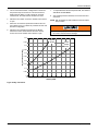
Enthalpy Set Point Chart . . . . . . . . . . . . . . . . . . . . . . . .
Honeywell Economizer Control W7212 . . . . . . . . . . . . .
Belt Adjustment . . . . . . . . . . . . . . . . . . . . . . . . . . . . . . .
Altitude/Temperature Correction Factors . . . . . . . . . . . .
Dry Coil Delta P . . . . . . . . . . . . . . . . . . . . . . . . . . . . . . .
Unit Control Board . . . . . . . . . . . . . . . . . . . . . . . . . . . . .
13
14
14
14
14
16
17
17
29
29
30
31
38
46
267233-YIM-B-0507
267233-YIM-B-0507
General
York® Predator® heat pumps are single package, reverse cycle
air conditioners designed for outdoor installation on a rooftop or
slab and for non-residential use. These units can be equipped
with factory or field installed electric heaters for heating
applications.
These units are completely assembled on rigid, permanently
attached base rails. All piping, refrigerant charge, and electrical
wiring is factory installed and tested. The units require electric
power and duct connections. The electric heaters have nickelchrome elements and utilize single-point power connection.
Before performing service or maintenance operations on
unit, turn off main power switch to unit. Electrical shock
could cause personal injury. Improper installation,
adjustment, alteration, service or maintenance can
cause injury or property damage. Refer to this manual.
For assistance or additional information consult a
qualified installer or service agency.
Safety Considerations
This is a safety alert symbol. When you see this symbol on
labels or in manuals, be alert to the potential for personal injury.
Understand and pay particular attention the signal words
DANGER, WARNING or CAUTION.
DANGER indicates an imminently hazardous situation, which,
if not avoided, will result in death or serious injury.
WARNING indicates a potentially hazardous situation, which,
if not avoided, could result in death or serious injury.
CAUTION indicates a potentially hazardous situation, which, if
not avoided may result in minor or moderate injury. It is also
used to alert against unsafe practices and hazards involving
only property damage.
Improper installation may create a condition where the
operation of the product could cause personal injury or
property damage. Improper installation, adjustment,
alteration, service or maintenance can cause injury or
property damage. Refer to this manual for assistance or
for additional information, consult a qualified contractor,
installer or service agency.
This system uses R-410A Refrigerant which operates at
higher pressures than R-22. No other refrigerant may be
used in this system. Gage sets, hoses, refrigerant
containers and recovery systems must be designed to
handle R-410A. If you are unsure, consult the equipment
manufacturer. Failure to use R-410A compatible servicing
equipment may result in property damage or injury.
Due to system pressure, moving parts, and electrical
components, installation and servicing of air conditioning
equipment can be hazardous. Only qualified, trained service
personnel should install, repair, or service this equipment.
Untrained personnel can perform basic maintenance functions
of cleaning coils and filters and replacing filters.
Observe all precautions in the literature, labels, and tags
accompanying the equipment whenever working on air
conditioning equipment. Be sure to follow all other applicable
safety precautions and codes including National Electric Code,
ANSI/NFPA No. 70 - latest edition U.S. A. and Canadian
Electric Code, CSA C22.1 in Canada.
Wear safety glasses and work gloves. Use quenching cloth and
have a fire extinguisher available during brazing operations.
Inspection
As soon as a unit is received, it should be inspected for possible
damage during transit. If damage is evident, the extent of the
damage should be noted on the carrier’s freight bill. A separate
request for inspection by the carrier’s agent should be made in
writing.
This product must be installed in strict compliance with
the installation instructions and any applicable local,
state and national codes including, but not limited to
building, electrical, and mechanical codes.
2
Unitary Products Group
267233-YIM-B-0507
Reference
2.
For outdoor installation only.
Additional information is available in the following reference
forms:
3.
For installation on combustible material and may be
installed directly on combustible flooring or, in the U.S., on
wood flooring or Class A, Class B or Class C roof covering
materials.
• Technical Guide - ZH/XP078-150, 246824
• General Installation - XP078-150, 267233
• Pre-start & Post-start Check List
• Economizer Accessory Downflow Factory Installed
Downflow Field Installed
Horizontal Field Installed
• Motorized Outdoor Air Damper
• Manual Outdoor Air Damper (0-100%)
This product must be installed in strict compliance with
the enclosed installation instructions and any applicable
local, state, and national codes including, but not limited
to, building, electrical, and mechanical codes.
• Manual Outdoor Air Damper (0-35%)
• Electric Heater Accessory 50” cabinet
• Electric Heater Accessory 42” cabinet
Renewal Parts
Contact your local York® parts distribution center for authorized
replacement parts.
Improper installation may create a condition where the
operation of the product could cause personal injury or
property damage.
Approvals
Design certified by CSA as follows:
1.
For use as a cooling only unit, cooling unit with
supplemental electric heat or a forced air furnace.
Unitary Products Group
This system uses R-410A Refrigerant which operates at
higher pressures than R-22. No other refrigerant may be
used in this system.
3
267233-YIM-B-0507
Nomenclature
6.5-12.5 Ton York® Model Number Nomenclature
X P 090 C00 A 2 A AA 3 0 1 2 4 A
Product Category
Product Style
X = HP, Single Pkg., R-410A
A = Style A
B = Style B
C = Style C
Product Identifier
Configuration Options (not required for all units)
These four digits will not be assigned until a quote is requested, or an order placed.
P = 11.0 EER HP
SS Drain Pan
Nominal Cooling Capacity
CPC Controller, DFS, APS
078 = 6.5 Ton
090 = 7.5 Ton
102 = 8.5 Ton
120 = 10.0 Ton
150 = 12.5 Ton
Honeywell Controller, DFS, APS
Johnson Controller, DFS, APS
Novar Controller, DFS, APS
Simplicity IntelliComfort Controller
Simplicity IntelliComfort Controller w/ModLinc
2" Pleated filters
BAS Ready Economizer (2-10 V.D.C. Actuator without a Controller)
Heat Type and Nominal Heat Capacity
Shipping Bag
Any Combination of Additional Options that Don’t Have an Option Code Pre-assigned
C00 = Cooling Only. No heat installed
Electric Heat Options
Product Generation
E09 = 9 KW
E18 = 18 KW
E24 = 24 KW
E36 = 36 KW
E54 = 54 KW
3 = Third Generation
4 = Fourth Generation
Additional Options
Airflow
A = Std. Motor
B = Std. Motor/Econo./Barometric Relief (Downflow
Only)
C = Std. Motor/Econo./Power Exhaust (Downflow Only)
D = Std. Motor/Motorized Damper (Downflow Only)
E = Std. Motor/Horizontal Economizer (No Baro.)
F = Std. Motor/Slab Econo./Power Exhaust
(Downflow Only)
G = Std. Motor/Slab Econo./Barometric Relief
(Downflow Only)
N = Hi Static Mtr.
P = Hi Static Mtr./Econo./Barometric Relief
(Downflow Only)
Q = Hi Static Mtr./Econo./Power Exhaust
(Downflow Only)
R = Hi Static Mtr./Motorized Damper (Downflow Only)
S = Hi Static Mtr./Horizontal Economizer (No Baro.)
T = Hi Static Mtr./Slab Econo./Power Exhaust
(Downflow Only)
U = Hi Static Mtr./Slab Econo./Barometric Relief
(Downflow only)
Voltage
2 = 208/230-3-60
4 = 460-3-60
5 = 575-3-60
AA = None
AB = Phase Monitor
AC = Coil Guard
AD = Dirty Filter Switch
AE = Phase Monitor & Coil Guard
AF = Phase Monitor & Dirty Filter Switch
AG = Coil Guard & Dirty Filter Switch
AH = Phase Monitor, Coil Guard & Dirty Filter Switch
RC = Coil Guard, Shipping Bag & American Flag
TA = Technicoat Condenser Coil
TJ = Technicoat Evaporator Coil
TS = Technicoat Evaporator & Condenser Coils
ZZ = If desired option combination is not listed above, ZZ will be assigned and configuration options will be
located in digits 15-18.
Installation Options
A = No Options Installed
B = Option 1
C = Option 2
D = Options 1 & 2
E = Option 3
F = Option 4
G = Options 1 & 3
H = Options 1 & 4
J = Options 1, 2 & 3
K = Options 1, 2, & 4
L = Options 1,3 & 4
M = Options 1, 2, 3, & 4
N = Options 2 & 3
P = Options 2 & 4
Q = Options 2, 3, & 4
R = Options 3 & 4
S = Option 5
T = Options 1 & 5
U = Options 1, 3, & 5
V = Options 1, 4, & 5
W = Options 1, 3, 4, & 5
X = Options 3 & 5
Y = Options 4 & 5
Z = Options 3, 4 & 5
Options
1 = Disconnect
2 = Non-Pwr'd Conv. Outlet
3 = Smoke Detector S.A.
4 = Smoke Detector R.A.
5 = Pwr'd Conv. Outlet
4
Unitary Products Group
267233-YIM-B-0507
Installation
Installation Safety Information
Read these instructions before continuing this appliance
installation. This is an outdoor combination heating and cooling
unit. The installer must assure that these instructions are made
available to the consumer and with instructions to retain them
for future reference.
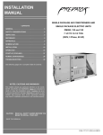
7RROOHVV
'RRUNQREV
This equipment is not to be used for temporary heating of
buildings or structures under construction.
,QVWDOODWLRQ
,QVWUXFWLRQ
3DFNHW
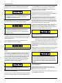
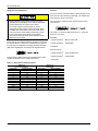
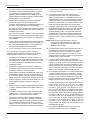
FIRE OR EXPLOSION HAZARD
Failure to follow the safety warning exactly could result
in serious injury, death or property damage.
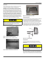
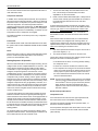
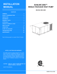
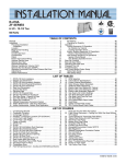
Figure 3: Compressor Section
Never test for gas leaks with an open flame. use a
commercially available soap solution made specifically
for the detection of leaks to check all connections. A fire
or explosion may result causing property damage,
personal injury or loss of life.
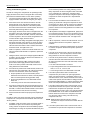
Limitations
Preceding Installation
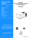
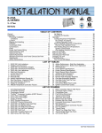
1.
Remove the two screws holding the brackets in the front,
rear and compressor side fork-lift slots.
These units must be installed in accordance with the following:
In U.S.A.:
1.
National Electrical Code, ANSI/NFPA No. 70 - Latest
Edition
2.
Local building codes, and
3.
Local electric utility requirements
In Canada:
1.
%UDFNHW
6FUHZV
7XUQGRZQ
Figure 1: Unit Shipping Bracket
2.
Turn each bracket toward the ground and the protective
plywood covering will drop to the ground.
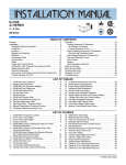
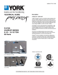
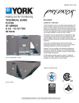
3.
Remove the condenser coil external protective covering
prior to operation.
4.
Remove the toolless doorknobs and instruction packet
prior to installation.
&RQGHQVHU
&RLO([WHUQDO
3URWHFWLYH
&RYHULQJ
Canadian Electrical Code, CSA C22.1
2.
Installation Codes, CSA - B149.1.
3.
Local plumbing and waste water codes, and
4.
Other applicable local codes.
Refer to unit application data found in this document.
If components are to be added to a unit to meet local codes,
they are to be installed at the dealer’s and/or customer’s
expense.
Size of unit for proposed installation should be based on heat
loss/heat gain calculation made according to the methods of Air
Conditioning Contractors of America (ACCA).
This furnace is not to be used for temporary heating of buildings
or structures under construction.
%DURPHWULF
5HOLHI+RRG
LQ6KLSSLQJ
/RFDWLRQ
LI,QFOXGHG
Figure 2: Condenser Covering
Unitary Products Group
5
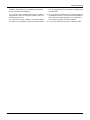
267233-YIM-B-0507
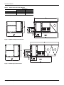
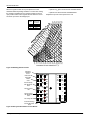
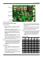
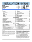
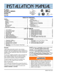
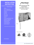
Simplicity® Control
board w/screw connectors for T-stat wiring and
network connection
Disconnect location
(optional disconnect switch)
Terminal block
for hi-voltage
connection
Filter access
(2” throw-away)
Filter drier (solid core)
Condenser
section
Second Model
Nameplate Inside
Control Door
Slide-out motor and
blower assembly for
easy adjustment and
service.
Dual stage cooling for maximum
comfort (7-1/2 12-1/2 Only)
Compressor #2
Access (High-Eff
Compressor)
Base Rails w/ Forklift Slots (3 Sides)
& Lifting Holes
Belt-drive
blower
motor
Roof curbs in eight- and
fourteen-inch heights. Roof
curbs for transitioning from
Sunline™ footprint to the
XP series footprint are also
available (field installed
accessory)
Toolless
Door Latch
Side entry power
and control wiring
knockouts
Compressor #1 Access
(High-Eff Compressor)
Slide-out drain pain
with steel 3/4” NPT,
Female Connection
Figure 4: Predator® Component Location
6
Unitary Products Group
267233-YIM-B-0507
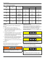
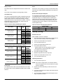
Table 1:
XP078-150 Unit Limitations
Unit Limitations
Size
(Tons)
078
(6.5)
090
(7.5)
102
(8.5)
120
(10)
150
(12.5)
Model
Unit Voltage
Applied Voltage
Outdoor DB Temp
Min
Max
Max (°F)
208/230-3-60
187
252
125
460-3-60
432
504
125
575-3-60
540
630
125
208/230-3-60
187
252
125
460-3-60
432
504
125
575-3-60
540
630
125
208/230-3-60
187
252
125
460-3-60
432
504
125
575-3-60
540
630
125
208/230-3-60
187
252
125
460-3-60
432
504
125
575-3-60
540
630
125
208/230-3-60
187
252
125
460-3-60
432
504
125
575-3-60
540
630
125
XP
XP
XP
XP
XP
Location
Rigging And Handling
Use the following guidelines to select a suitable location for
these units:
Exercise care when moving the unit. Do not remove any
packaging until the unit is near the place of installation. Rig the
unit by attaching chain or cable slings to the lifting holes
provided in the base rails. Spreader bars, whose length
exceeds the largest dimension across the unit, MUST be used
across the top of the unit.
1.
Unit is designed for outdoor installation only.
2.
Condenser coils must have an unlimited supply of air.
Where a choice of location is possible, position the unit on
either north or east side of building.
3.
Suitable for mounting on roof curb.
4.
For ground level installation, use a level concrete slab with
a minimum thickness of 4 inches. The length and width
should be at least 6 inches greater than the unit base rails.
Do not tie slab to the building foundation.
5.
Roof structures must be able to support the weight of the
unit and its options/accessories. Unit must be installed on a
solid, level roof curb or appropriate angle iron frame.
6.
Maintain level tolerance to 1/2” across the entire width and
length of unit.
Clearances
All units require particular clearances for proper operation and
service. Refer to Table 5 for clearances required for
construction, servicing, and proper unit operation.
If a unit is to be installed on a roof curb other than a
York® roof curb, gasketing must be applied to all
surfaces that come in contact with the unit underside.
Before lifting, make sure the unit weight is distributed
equally on the rigging cables so it will lift evenly.
Units may be moved or lifted with a forklift. Slotted openings in
the base rails are provided for this purpose.
LENGTH OF FORKS MUST BE A MINIMUM OF 60 INCHES.
Do not permit overhanging structures or shrubs to
obstruct condenser air discharge outlet, combustion air
inlet or vent outlets.
All panels must be secured in place when the unit is
lifted.
The condenser coils should be protected from rigging
cable damage with plywood or other suitable material.
Unitary Products Group
7
267233-YIM-B-0507
FRONT
FRONT
LEFT
B
LEFT
C
B
A
A
D
C
E
D
F
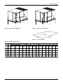
Figure 5: Unit 4 Point Load Weight
Figure 6: Unit 6 Point Load Weight
Y
X
FRONT
LEFT
Figure 7: Center of Gravity
Table 2:
Weights and Dimensions
Weight (lbs.)
Center of Gravity
Size
Model
(Tons)
Shipping Operating
X
Y
078
XP
925
920
38
23
(6.5)
090
XP
925
920
38
23
(7.5)
102
XP
1140
1135
38
25.5
(8.5)
120
XP
1140
1135
38
25.5
(10)
150
XP
1405
1400
51
25.5
(12.5)
8
4 Point Load Location (lbs.)
A
B
C
D
A
6 Point Load Location (lbs.)
B
C
D
E
F
206
153
240
322
144
117
97
152
184
225
206
153
240
322
144
117
97
152
184
225
281
209
275
369
197
160
133
175
211
259
281
209
275
369
197
160
133
175
211
259
258
347
456
339
164
198
243
319
260
216
Unitary Products Group
267233-YIM-B-0507
Table 3:
XP078-150 Unit Accessory Weights
Unit Accessory
Economizer
Power Exhaust
Electric Heat1
Weight (lbs.)
Shipping
Operating
90
85
155
150
80
80
1. Weight given is for the maximum heater size available (54KW).
See detail A for drain location
Figure 8: XP078-120 Physical Dimensions
See detail A for drain location
Figure 9: XP150 Physical Dimensions
Unitary Products Group
9
267233-YIM-B-0507
Table 4:
XP078-150 Unit Physical Dimensions
Unit Model Number
A
42
42
50 3/4
50 3/4
50 3/4
XP078
XP090
XP102
XP120
XP150
B
89
89
89
89
119 1/2
Dimension (in.)
C
D
22 1/8
18 3/16
22 1/8
18 3/16
30 3/16
24 3/16
30 3/16
24 3/16
30 3/16
24 3/16
E
15 3/16
15 3/16
17 3/16
17 3/16
17 3/16
F
6 3/16
6 3/16
6 3/16
6 3/16
6 3/16
Detail A
Table 5:
XP078-150 Unit Clearances
Direction
Top1
Front
Rear
Distance (in.)
72
36
36
Direction
Right
Left
Bottom2
Distance (in.)
12
36
0
1. Units must be installed outdoors. Over hanging structure or shrubs should not obscure condenser air discharge outlet.
2. Units may be installed on combustable floors made from wood or class A, B or C roof covering materials.
Figure 10: XP078-150 Unit Bottom Duct Openings
10
Unitary Products Group
267233-YIM-B-0507
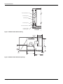
'LVFRQQHFW6ZLWK&RYHU
3RZHU(QWU\
&RQWURO(QWU\
3RZHU(QWU\
&RQYHQLHQFH2XWOHW&RYHU
&RQYHQLHQFH2XWOHW
3RZHU(QWU\
)5217
Figure 11: XP078-150 Unit Electrical Entry
18-1/4
Dot Plugs
A
Return
Air
Supply
Air
D
B
2-31/32
5-5/32
C
31-11/16
Figure 12: XP078-120 Unit Side Duct Openings
Unitary Products Group
11
267233-YIM-B-0507
Dot Plugs
18-1/4
A
D
B
5-5/32
2-7/8
C
31-5/8
Figure 13: XP150 Unit Side Duct Openings
Table 6:
Side Duct Dimensions
Unit Model Number
Dimension (in.)
A
B
C
D
XP078
27 3/4
12 1/16
27 1/2
16
XP090
27 3/4
12 1/16
27 1/2
16
XP102
28 1/4
18 1/16
28 1/4
18 1/4
XP120
28 1/4
18 1/16
28 1/4
18 1/4
XP150
28 1/4
18 1/16
28 1/4
18 1/4
Figure 14: XP078-150 Unit Left Duct Opening
12
Unitary Products Group
267233-YIM-B-0507
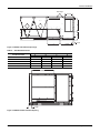
RIGHT
80-5/8
INSULATED DECK UNDER
CONDENSER SECTION
20
SUPPLY
20
6
RETURN
2 TYP.
30
INSULATED DECK UNDER
COMPRESSOR SECTION
50-1/2
FRONT
8 or 14
Figure 15: XP078-150 Roof Curb
7<3
5(7851
6833/<
)5217
5,*+7
Figure 16: XP078-150 Transition Roof Curb
Ductwork
Ductwork should be designed and sized according to the
methods in Manual D of the Air Conditioning Contractors of
America (ACCA) or as recommended by any other recognized
authority such as ASHRAE or SMACNA.
A closed return duct system should be used. This will not
preclude use of economizers or outdoor fresh air intake. The
Unitary Products Group
supply and return air duct connections at the unit should be
made with flexible joints to minimize noise.
The supply and return air duct systems should be designed for
the CFM and static pressure requirements of the job. They
should NOT be sized to match the dimensions of the duct
connections on the unit.
Refer to Figure 10 for bottom air duct openings. Refer to
Figures 12, 13 and Table 6 for side air duct openings.
13
267233-YIM-B-0507
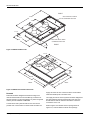
Duct Covers
Units are shipped with the side duct openings covered and a
covering over the bottom of the unit. For bottom duct
application, no duct cover changes are necessary. For side
duct application, remove the side duct covers and install over
the bottom duct openings. The panels removed from the side
duct connections are designed to be reused by securing each
panel to its respective downflow opening. But keep in mind that
the supply panel is installed with the painted surface UP, facing
the heat exchanger, while the return panel is installed with the
painted surface DOWN, facing the downflow duct opening. The
supply panel is secured with the bracket (already in place from
the factory) and two screws. It’s a snug fit for the panel when
sliding it between the heat exchanger and unit bottom, but there
is room. The return panel is secured with four screws.
When fastening ductwork to side duct flanges on unit,
insert screws through duct flanges only. DO NOT insert
screws through casing. Outdoor ductwork must be
insulated and water-proofed.
Figure 19: Discharge Panel In Place
Condensate Drain
The side condensate drain is reversible and maybe re-oriented to
the rear of the cabinet to facilitate condensate piping. A
condensate drain connection is available through the base pan
for piping inside the roof curb. Trap the connection per Figure 20.
The trap and drain lines should be protected from freezing.
Plumbing must conform to local codes. Use a sealing compound
on male pipe threads. Install condensate drain line from the 3/4
inch NPT female connection on the unit to an open drain.
237,21$/&2,/
*8$5'
0LQLPXP
Figure 17: Side Panels With Hole Plugs
NOTE: Orientation. Panel is “insulation” side up.
Figure 20: Condensate Drain
Compressors
The scroll compressor used in this product is specifically
designed to operate with R-410A Refrigerant and cannot be
interchanged.
Figure 18: Return Downflow Plenum With Panel
This system uses R-410A Refrigerant which operates at
higher pressures than R-22. No other refrigerant may be
used in this system.
The compressor also uses a polyolester (POE oil), Mobil 3MA
POE. This oil is extremely hygroscopic, meaning it absorbs water
readily. POE oil can absorb 15 times as much water as other oils
14
Unitary Products Group
267233-YIM-B-0507
designed for HCFC and CFC refrigerants. Take all necessary
precautions to avoid exposure of the oil to the atmosphere.
Do not leave the system open to the atmosphere. Unit
damage could occur due to moisture being absorbed by
the POE oil in the system. This type of oil is highly
susceptible to moisture absorption
POE (polyolester) compressor lubricants are known to cause
long term damage to some synthetic roofing materials.
Exposure, even if immediately cleaned up, may cause
embrittlement (leading to cracking) to occur in one year
or more. When performing any service that may risk
exposure of compressor oil to the roof, take precautions
to protect roofing.
Procedures which risk oil leakage include, but are not limited to,
compressor replacement, repairing refrigerant leaks, replacing
refrigerant components such as filter drier, pressure switch,
metering device or coil.
Units are shipped with compressor mountings which are
factory-adjusted and ready for operation.
Do not loosen compressor mounting bolts.
Filters
Two-inch filters are supplied with each unit. One-inch filters may
be used with no modification to the filter racks. Filters must
always be installed ahead of evaporator coil and must be kept
clean or replaced with same size and type. Dirty filters reduce
the capacity of the unit and result in frosted coils or safety
shutdown. Refer to physical data tables, for the number and
size of filters needed for the unit. The unit should not be
operated without filters properly installed.
70 – Latest Edition (in U.S.A.), current Canadian Electrical
Code C221, and/or local ordinances. The unit must be
electrically grounded in accordance with NEC and CEC as
specified above and/or local codes.
Voltage tolerances which must be maintained at the
compressor terminals during starting and running conditions are
indicated on the unit Rating Plate and Table 1.
The internal wiring harnesses furnished with this unit are an
integral part of the design certified unit. Field alteration to
comply with electrical codes should not be required. If any of
the wire supplied with the unit must be replaced, replacement
wire must be of the type shown on the wiring diagram and the
same minimum gauge as the replaced wire.
A disconnect must be utilized for these units. Factory installed
disconnects are available. If installing a disconnect (field
supplied or York International® supplied accessory), refer to
Figure 4 for the recommended mounting location.
Avoid damage to internal components if drilling holes for
disconnect mounting.
NOTE: Since not all local codes allow the mounting of a
disconnect on the unit, please confirm compliance with
local code before mounting a disconnect on the unit.
Electrical line must be sized properly to carry the load. USE
COPPER CONDUCTORS ONLY. Each unit must be wired with
a separate branch circuit fed directly from the meter panel and
properly fused.
Refer to Figures 21, 22 and 23 for typical field wiring and to the
appropriate unit wiring diagram mounted inside control doors
for control circuit and power wiring information.
When connecting electrical power and control wiring to
the unit, water-proof connectors must be used so that
water or moisture cannot be drawn into the unit during
normal operation. The above water-proofing conditions
will also apply when installing a field supplied disconnect
switch.
Power Wiring Detail
Make sure that panel latches are properly positioned on
the unit to maintain an airtight seal.
Power And Control Wiring
Units are factory wired for the voltage shown on the unit
nameplate. Refer to Electrical Data Table 8 to size power
wiring, fuses, and disconnect switch.
Power wiring is brought into the unit through the side of the unit
or the basepan inside the curb.
Field wiring to the unit, fuses, and disconnects must conform to
provisions of National Electrical Code (NEC), ANSI/NFPA No.
Unitary Products Group
15
267233-YIM-B-0507
7(50,1$/%/2&.7%
*5281'
/8*
)$&725<25),(/'
6833/,('',6&211(&7
7+5((
3+$6(
32:(5
6833/<
Figure 21: Field Wiring Disconnect - Cooling Unit With/Without Electric Heat
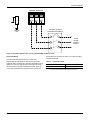
Thermostat Wiring
The thermostat should be located on an inside wall
approximately 56 inch above the floor where it will not be
subject to drafts, sun exposure or heat from electrical fixtures or
appliances. Follow the manufacturer's instructions enclosed
with thermostat for general installation procedure. Seven (7)
color-coded, insulated wires should be used to connect the
16
thermostat to the unit. Refer to Table 7 for control wire sizing
and maximum length.
Table 7:
Control Wire Sizes
Wire Size
Maximum Length1
18 AWG
150 Feet
1. From the unit to the thermostat and back to the unit.
Unitary Products Group
267233-YIM-B-0507
7+(50267$7
7(50,1$/6
81,77(50,1$/6
675,37%
5&
5+
5
<
<
<
<
:
:
:
:
*
*
&
&
;
9ROW
7UDQVIRUPHU
;
;
2&&
;
$
$
7
7
725(027(6(1625
(7,)86('
(OHFWURQLFSURJUDPPDEOH7KHUPRVWDW(7LQFOXGHVVXEEDVH
7HUPLQDOV$DQG$SURYLGHDUHOD\RXWSXWWRFORVHWKHRXWGRRUHFRQRPL]HU
GDPSHUVZKHQWKHWKHUPRVWDWVZLWFKHVWRWKHVHWEDFNSRVLWLRQ
Figure 22: Electronic Thermostat Field Wiring
767$7
:
:
:
:
<
<
*
*
<
2&&
5+
5&
5(027(
0,1326
&
81,7&21752/
%2$5'
<
;
5
6'
&
Figure 23: Field Wiring 24 Volt Thermostat
Unitary Products Group
17
267233-YIM-B-0507
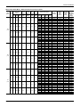
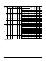
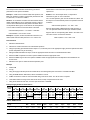
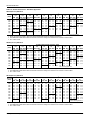
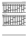
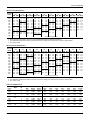
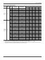
Table 8:
Electrical Data
XP078-150 Standard Motor - Without Powered Convenience Outlet
Size
(Tons)
Volt
Compressors
(each)
RLA LRA
MCC
OD Fan
Motors
(each)
Supply
Blower
Motor
Pwr
Exh
Motor
Pwr
Conv
Outlet
FLA
FLA
FLA
FLA
208
14.1
95.0
22.0
1.5
6.2
5.5
0.0
230
14.1
95.0
22.0
1.5
6.2
5.5
0.0
460
6.4
45.0
10.0
0.8
3.1
2.2
0.0
575
5.4
38.0
8.5
0.6
2.4
1.8
0.0
208
15.6
83.1
21.4
1.5
6.2
5.5
0.0
230
15.6
83.1
21.4
1.5
6.2
5.5
0.0
460
6.9
41.0
9.7
0.8
3.1
2.2
0.0
575
5.4
33.0
7.5
0.6
2.4
1.8
0.0
208
16.7 120.0 26.0
1.5
8.2
5.5
0.0
230
16.7 120.0 26.0
1.5
8.2
5.5
0.0
460
8.7
60.0
13.5
0.8
4.1
2.2
0.0
575
6.7
42.0
10.5
0.6
3.6
1.8
0.0
078
(6.5)
090
(7.5)
102
(8.5)
18
Electric Heat Option
Model
kW
Stages
Amps
None
E09
E18
E24
E36
None
E09
E18
E24
E36
None
E09
E18
E24
E36
None
E09
E18
E24
E36
None
E09
E18
E24
E36
None
E09
E18
E24
E36
None
E09
E18
E24
E36
None
E09
E18
E24
E36
None
E09
E18
E24
E36
None
E09
E18
E24
E36
None
E09
E18
E24
E36
None
E09
E18
E24
E36
6.8
13.5
18.0
25.5
9.0
18.0
24.0
34.0
9.0
18.0
24.0
34.0
9.0
18.0
24.0
34.0
6.8
13.5
18.0
25.5
9.0
18.0
24.0
34.0
9.0
18.0
24.0
34.0
9.0
18.0
24.0
34.0
6.8
13.5
18.0
25.5
9.0
18.0
24.0
34.0
9.0
18.0
24.0
34.0
9.0
18.0
24.0
34.0
1
2
2
2
1
2
2
2
1
2
2
2
1
2
2
2
1
2
2
2
1
2
2
2
1
2
2
2
1
2
2
2
1
2
2
2
1
2
2
2
1
2
2
2
1
2
2
2
18.9
37.5
50.0
70.8
22.6
45.2
60.2
85.3
11.3
22.6
30.1
42.7
9.0
18.1
24.1
34.1
18.9
37.5
50.0
70.8
22.6
45.2
60.2
85.3
11.3
22.6
30.1
42.7
9.0
18.1
24.1
34.1
18.9
37.5
50.0
70.8
22.6
45.2
60.2
85.3
11.3
22.6
30.1
42.7
9.0
18.1
24.1
34.1
MCA1
(Amps)
MCA1
w/Pwr
Exh
(Amps)
40.9
64.5
87.8
103.4
129.4
40.9
68.0
95.1
113.1
143.2
19.1
32.6
46.2
55.2
70.2
15.8
26.6
37.4
44.6
56.6
44.3
67.9
91.1
106.8
132.8
44.3
71.4
98.4
116.5
146.5
20.2
33.8
47.3
56.3
71.3
15.8
26.6
37.4
44.6
56.6
48.8
72.4
95.6
111.2
137.3
48.8
75.8
102.9
120.9
151.0
25.3
38.8
52.3
61.4
76.4
19.9
30.7
41.5
48.7
60.8
46.4
70.0
93.3
108.9
134.9
46.4
73.5
100.6
118.6
148.7
21.3
34.8
48.4
57.4
72.4
17.6
28.4
39.2
46.4
58.4
49.8
73.4
96.6
112.3
138.3
49.8
76.9
103.9
122.0
152.0
22.4
36.0
49.5
58.5
73.5
17.6
28.4
39.2
46.4
58.4
54.3
77.9
101.1
116.7
142.8
54.3
81.3
108.4
126.4
156.5
27.5
41.0
54.5
63.6
78.6
21.7
32.5
43.3
50.5
62.6
2
Max Fuse2/ Max Fuse3 /
Breaker3 Breaker
Size w/
Size
Pwr Exh
(Amps)
(Amps)
50
60
70
70
90
100
110
110
150
150
50
60
70
80
100
110
125
125
150
150
25
25
35
35
50
50
60
60
80
80
20
20
30
30
40
40
45
50
60
60
50
60
70
80
100
100
110
125
150
150
50
60
80
80
100
110
125
125
150
175
25
25
35
40
50
50
60
60
80
80
20
20
30
30
40
40
45
50
60
60
60
70
80
80
100
110
125
125
150
150
60
70
80
90
110
110
125
150
175
175
30
35
40
45
60
60
70
70
80
80
25
25
35
35
45
45
50
60
70
70
Unitary Products Group
267233-YIM-B-0507
XP078-150 Standard Motor - Without Powered Convenience Outlet (Continued)
Size
(Tons)
Volt
Compressors
(each)
RLA LRA
MCC
OD Fan
Motors
(each)
Supply
Blower
Motor
Pwr
Exh
Motor
Pwr
Conv
Outlet
FLA
FLA
FLA
FLA
208
17.9 120.0 28.0
1.5
8.2
5.5
0.0
230
17.9 120.0 28.0
1.5
8.2
5.5
0.0
460
9.6
70.0
15.0
0.8
4.1
2.2
0.0
575
7.4
53.0
11.5
0.6
3.6
1.8
0.0
208
23.1 160.0 36.0
1.5
10.9
5.5
0.0
230
23.1 160.0 36.0
1.5
10.9
5.5
0.0
460
12.2
87.0
19.0
0.8
5.3
2.2
0.0
575
8.7
62.0
13.5
0.6
4.1
1.8
0.0
120
(10)
150
(12.5)
Electric Heat Option
MCA
(Amps)
MCA1
w/Pwr
Exh
(Amps)
51.5
98.3
113.9
140.0
151.1
51.5
105.6
123.6
153.7
153.7
27.3
54.4
63.4
78.4
78.4
21.5
43.1
50.3
62.3
62.3
68.9
115.7
131.3
157.4
157.4
68.9
123.0
141.0
171.1
171.1
36.0
63.0
72.0
87.1
87.1
26.1
47.7
54.9
67.0
67.0
57.0
103.8
119.4
145.5
158.0
57.0
111.1
129.1
159.2
159.2
29.5
56.6
65.6
80.6
80.6
23.3
44.9
52.1
64.1
64.1
74.4
121.2
136.8
162.9
162.9
74.4
128.5
146.5
176.6
176.6
38.2
65.2
74.2
89.3
89.3
27.9
49.5
56.7
68.8
68.8
1
Model
kW
Stages
Amps
None
E18
E24
E36
E54
None
E18
E24
E36
E54
None
E18
E24
E36
E54
None
E18
E24
E36
E54
None
E18
E24
E36
E54
None
E18
E24
E36
E54
None
E18
E24
E36
E54
None
E18
E24
E36
E54
13.5
18.0
25.5
40.6
18.0
24.0
34.0
54.0
18.0
24.0
34.0
54.0
18.0
24.0
34.0
54.0
13.5
18.0
25.5
40.6
18.0
24.0
34.0
54.0
18.0
24.0
34.0
54.0
18.0
24.0
34.0
54.0
2
2
2
2
2
2
2
2
2
2
2
2
2
2
2
2
2
2
2
2
2
2
2
2
2
2
2
2
2
2
2
2
37.5
50.0
70.8
112.7
45.2
60.2
85.3
135.6
22.6
30.1
42.7
67.8
18.1
24.1
34.1
54.2
37.5
50.0
70.8
112.7
45.2
60.2
85.3
135.6
22.6
30.1
42.7
67.8
18.1
24.1
34.1
54.2
2
Max Fuse2/ Max Fuse3 /
Breaker3 Breaker
Size w/
Size
Pwr Exh
(Amps)
(Amps)
60
70
100
110
125
125
150
150
175
175
60
70
110
125
125
150
175
175
175
175
35
35
60
60
70
70
80
90
80
90
25
30
45
45
60
60
70
70
70
70
90
90
125
125
150
150
175
175
175
175
90
90
125
150
150
150
175
200
175
200
45
50
70
70
80
80
90
90
90
90
30
35
50
50
60
60
70
70
70
70
1. Minimum Circuit Ampacity.
2. Dual Element, Time Delay Type.
3. HACR type per NEC.
Unitary Products Group
19
267233-YIM-B-0507
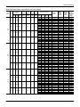
XP078-150 Hi Static Motor - Without Powered Convenience Outlet
Size
(Tons)
Volt
Compressors
(each)
RLA LRA
MCC
OD Fan
Motors
(each)
Supply
Blower
Motor
Pwr
Exh
Motor
Pwr
Conv
Outlet
FLA
FLA
FLA
FLA
208
14.1
95.0
22.0
1.5
8.2
5.5
0.0
230
14.1
95.0
22.0
1.5
8.2
5.5
0.0
460
6.4
45.0
10.0
0.8
4.1
2.2
0.0
575
5.4
38.0
8.5
0.6
3.6
1.8
0.0
208
15.6
83.1
21.4
1.5
10.9
5.5
0.0
230
15.6
83.1
21.4
1.5
10.9
5.5
0.0
460
6.9
41.0
9.7
0.8
5.3
2.2
0.0
575
5.4
33.0
7.5
0.6
4.1
1.8
0.0
208
16.7 120.0 26.0
1.5
10.9
5.5
0.0
230
16.7 120.0 26.0
1.5
10.9
5.5
0.0
460
8.7
60.0
13.5
0.8
5.3
2.2
0.0
575
6.7
42.0
10.5
0.6
4.1
1.8
0.0
078
(6.5)
090
(7.5)
102
(8.5)
20
Electric Heat Option
Model
kW
None
E09
E18
E24
E36
None
E09
E18
E24
E36
None
E09
E18
E24
E36
None
E09
E18
E24
E36
None
E09
E18
E24
E36
None
E09
E18
E24
E36
None
E09
E18
E24
E36
None
E09
E18
E24
E36
None
E09
E18
E24
E36
None
E09
E18
E24
E36
None
E09
E18
E24
E36
None
E09
E18
E24
E36
6.8
13.5
18.0
25.5
9.0
18.0
24.0
34.0
9.0
18.0
24.0
34.0
9.0
18.0
24.0
34.0
6.8
13.5
18.0
25.5
9.0
18.0
24.0
34.0
9.0
18.0
24.0
34.0
9.0
18.0
24.0
34.0
6.8
13.5
18.0
25.5
9.0
18.0
24.0
34.0
9.0
18.0
24.0
34.0
9.0
18.0
24.0
34.0
MCA1
(Amps)
MCA1
w/Pwr
Exh
(Amps)
42.9
66.5
89.8
105.4
131.4
42.9
70.0
97.1
115.1
145.2
20.1
33.6
47.2
56.2
71.2
17.0
27.8
38.6
45.8
57.8
49.0
72.6
95.8
111.5
137.5
49.0
76.1
103.1
121.2
151.2
22.4
36.0
49.5
58.5
73.5
17.5
28.3
39.1
46.3
58.3
51.5
75.1
98.3
113.9
140.0
51.5
78.5
105.6
123.6
153.7
26.5
40.0
53.5
62.6
77.6
20.4
31.2
42.0
49.2
61.3
48.4
72.0
95.3
110.9
136.9
48.4
75.5
102.6
120.6
150.7
22.3
35.8
49.4
58.4
73.4
18.8
29.6
40.4
47.6
59.6
54.5
78.1
101.3
117.0
143.0
54.5
81.6
108.6
126.7
156.7
24.6
38.2
51.7
60.7
75.7
19.3
30.1
40.9
48.1
60.1
57.0
80.6
103.8
119.4
145.5
57.0
84.0
111.1
129.1
159.2
28.7
42.2
55.7
64.8
79.8
22.2
33.0
43.8
51.0
63.1
Stages Amps
1
2
2
2
1
2
2
2
1
2
2
2
1
2
2
2
1
2
2
2
1
2
2
2
1
2
2
2
1
2
2
2
1
2
2
2
1
2
2
2
1
2
2
2
1
2
2
2
18.9
37.5
50.0
70.8
22.6
45.2
60.2
85.3
11.3
22.6
30.1
42.7
9.0
18.1
24.1
34.1
18.9
37.5
50.0
70.8
22.6
45.2
60.2
85.3
11.3
22.6
30.1
42.7
9.0
18.1
24.1
34.1
18.9
37.5
50.0
70.8
22.6
45.2
60.2
85.3
11.3
22.6
30.1
42.7
9.0
18.1
24.1
34.1
2
Max Fuse2/ Max Fuse3 /
Breaker
Breaker3
Size w/ Pwr
Size
Exh
(Amps)
(Amps)
50
60
70
80
90
100
110
125
150
150
50
60
70
80
100
110
125
125
150
175
25
25
35
40
50
50
60
60
80
80
20
20
30
30
40
45
50
50
60
60
60
70
80
80
100
110
125
125
150
150
60
70
80
90
110
110
125
150
175
175
25
30
40
40
50
60
60
70
80
80
20
20
30
35
40
45
50
50
60
70
60
70
80
90
100
110
125
125
150
150
60
70
80
90
110
125
125
150
175
175
35
35
45
45
60
60
70
70
80
80
25
25
35
35
45
45
50
60
70
70
Unitary Products Group
267233-YIM-B-0507
XP078-150 Hi Static Motor - Without Powered Convenience Outlet (Continued)
Size
(Tons)
Volt
Compressors
(each)
RLA LRA
MCC
OD Fan
Motors
(each)
Supply
Blower
Motor
Pwr
Exh
Motor
Pwr
Conv
Outlet
FLA
FLA
FLA
FLA
208
17.9 120.0 28.0
1.5
10.9
5.5
0.0
230
17.9 120.0 28.0
1.5
10.9
5.5
0.0
460
9.6
70.0
15.0
0.8
5.3
2.2
0.0
575
7.4
53.0
11.5
0.6
4.1
1.8
0.0
208
23.1 160.0 36.0
1.5
16.1
5.5
0.0
230
23.1 160.0 36.0
1.5
16.1
5.5
0.0
460
12.2
87.0
19.0
0.8
8.1
2.2
0.0
575
8.7
62.0
13.5
0.6
6.0
1.8
0.0
120
(10)
150
(12.5)
Electric Heat Option
Model
kW
None
E18
E24
E36
E54
None
E18
E24
E36
E54
None
E18
E24
E36
E54
None
E18
E24
E36
E54
None
E18
E24
E36
E54
None
E18
E24
E36
E54
None
E18
E24
E36
E54
None
E18
E24
E36
E54
13.5
18.0
25.5
40.6
18.0
24.0
34.0
54.0
18.0
24.0
34.0
54.0
18.0
24.0
34.0
54.0
13.5
18.0
25.5
40.6
18.0
24.0
34.0
54.0
18.0
24.0
34.0
54.0
18.0
24.0
34.0
54.0
MCA
(Amps)
MCA1
w/Pwr
Exh
(Amps)
54.2
101.0
116.6
142.7
154.5
54.2
108.3
126.3
156.4
156.4
28.5
55.6
64.6
79.6
79.6
22.0
43.6
50.8
62.8
62.8
74.1
120.9
136.5
162.6
162.6
74.1
128.2
146.2
176.3
176.3
38.8
65.8
74.8
89.9
89.9
28.0
49.6
56.8
68.9
68.9
59.7
106.5
122.1
148.2
161.4
59.7
113.8
131.8
161.9
161.9
30.7
57.8
66.8
81.8
81.8
23.8
45.4
52.6
64.6
64.6
79.6
126.4
142.0
168.1
168.1
79.6
133.7
151.7
181.8
181.8
41.0
68.0
77.0
92.1
92.1
29.8
51.4
58.6
70.7
70.7
1
Stages Amps
2
2
2
2
2
2
2
2
2
2
2
2
2
2
2
2
2
2
2
2
2
2
2
2
2
2
2
2
2
2
2
2
37.5
50.0
70.8
112.7
45.2
60.2
85.3
135.6
22.6
30.1
42.7
67.8
18.1
24.1
34.1
54.2
37.5
50.0
70.8
112.7
45.2
60.2
85.3
135.6
22.6
30.1
42.7
67.8
18.1
24.1
34.1
54.2
2
Max Fuse2/ Max Fuse3 /
Breaker
3
Breaker
Size w/ Pwr
Size
Exh
(Amps)
(Amps)
70
70
110
110
125
125
150
150
175
175
70
70
110
125
150
150
175
175
175
175
35
40
60
60
70
70
80
90
80
90
25
30
45
50
60
60
70
70
70
70
90
100
125
150
150
150
175
175
175
175
90
100
150
150
150
175
200
200
200
200
50
50
70
70
80
80
90
100
90
100
35
35
50
60
60
60
70
80
70
80
1. Minimum Circuit Ampacity.
2. Dual Element, Time Delay Type.
3. HACR type per NEC.
Unitary Products Group
21
267233-YIM-B-0507
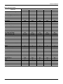
XP078-150 Standard Motor - With Powered Convenience Outlet
Size
(Tons)
Volt
Compressors
(each)
RLA LRA
MCC
OD Fan
Motors
(each)
Supply
Blower
Motor
Pwr
Exh
Motor
Pwr
Conv
Outlet
FLA
FLA
FLA
FLA
208
14.1
95.0
22.0
1.5
6.2
5.5
10.0
230
14.1
95.0
22.0
1.5
6.2
5.5
10.0
460
6.4
45.0
10.0
0.8
3.1
2.2
5.0
575
5.4
38.0
8.5
0.6
2.4
1.8
4.0
208
15.6
83.1
21.4
1.5
6.2
5.5
10.0
230
15.6
83.1
21.4
1.5
6.2
5.5
10.0
460
6.9
41.0
9.7
0.8
3.1
2.2
5.0
575
5.4
33.0
7.5
0.6
2.4
1.8
4.0
208
16.7 120.0 26.0
1.5
8.2
5.5
10.0
230
16.7 120.0 26.0
1.5
8.2
5.5
10.0
460
8.7
60.0
13.5
0.8
4.1
2.2
5.0
575
6.7
42.0
10.5
0.6
3.6
1.8
4.0
078
(6.5)
090
(7.5)
102
(8.5)
22
Electric Heat Option
Model
kW
None
E09
E18
E24
E36
None
E09
E18
E24
E36
None
E09
E18
E24
E36
None
E09
E18
E24
E36
None
E09
E18
E24
E36
None
E09
E18
E24
E36
None
E09
E18
E24
E36
None
E09
E18
E24
E36
None
E09
E18
E24
E36
None
E09
E18
E24
E36
None
E09
E18
E24
E36
None
E09
E18
E24
E36
–
6.8
13.5
18.0
25.5
–
9.0
18.0
24.0
34.0
–
9.0
18.0
24.0
34.0
–
9.0
18.0
24.0
34.0
6.8
13.5
18.0
25.5
9.0
18.0
24.0
34.0
9.0
18.0
24.0
34.0
9.0
18.0
24.0
34.0
–
6.8
13.5
18.0
25.5
–
9.0
18.0
24.0
34.0
–
9.0
18.0
24.0
34.0
–
9.0
18.0
24.0
34.0
MCA1
(Amps)
MCA1
w/Pwr
Exh
(Amps)
50.9
74.5
97.8
113.4
139.4
50.9
78.0
105.1
123.1
153.2
24.1
37.6
51.2
60.2
75.2
19.8
30.6
41.4
48.6
60.6
54.3
77.9
101.1
116.8
142.8
54.3
81.4
108.4
126.5
156.5
25.2
38.8
52.3
61.3
76.3
19.8
30.6
41.4
48.6
60.6
58.8
82.4
105.6
121.2
147.3
58.8
85.8
112.9
130.9
161.0
30.3
43.8
57.3
66.4
81.4
23.9
34.7
45.5
52.7
64.8
56.4
80.0
103.3
118.9
144.9
56.4
83.5
110.6
128.6
158.7
26.3
39.8
53.4
62.4
77.4
21.6
32.4
43.2
50.4
62.4
59.8
83.4
106.6
122.3
148.3
59.8
86.9
113.9
132.0
162.0
27.4
41.0
54.5
63.5
78.5
21.6
32.4
43.2
50.4
62.4
64.3
87.9
111.1
126.7
152.8
64.3
91.3
118.4
136.4
166.5
32.5
46.0
59.5
68.6
83.6
25.7
36.5
47.3
54.5
66.6
Stages Amps
–
1
2
2
2
–
1
2
2
2
–
1
2
2
2
–
1
2
2
2
1
2
2
2
1
2
2
2
1
2
2
2
1
2
2
2
–
1
2
2
2
–
1
2
2
2
–
1
2
2
2
–
1
2
2
2
–
18.9
37.5
50.0
70.8
–
22.6
45.2
60.2
85.3
–
11.3
22.6
30.1
42.7
–
9.0
18.1
24.1
34.1
18.9
37.5
50.0
70.8
22.6
45.2
60.2
85.3
11.3
22.6
30.1
42.7
9.0
18.1
24.1
34.1
–
18.9
37.5
50.0
70.8
–
22.6
45.2
60.2
85.3
–
11.3
22.6
30.1
42.7
–
9.0
18.1
24.1
34.1
2
Max Fuse2/ Max Fuse3 /
Breaker
Breaker3
Size w/ Pwr
Size
Exh
(Amps)
(Amps)
60
70
80
80
100
110
125
125
150
150
60
70
80
90
110
125
125
150
175
175
30
30
40
40
60
60
70
70
80
80
25
25
35
35
45
45
50
60
70
70
60
70
80
90
110
110
125
125
150
150
60
70
90
90
110
125
150
150
175
175
30
30
40
45
60
60
70
70
80
80
25
25
35
35
45
45
50
60
70
70
70
80
90
90
110
125
125
150
150
175
70
80
90
100
125
125
150
150
175
175
35
40
45
50
60
60
70
70
90
90
30
30
35
40
50
50
60
60
70
70
Unitary Products Group
267233-YIM-B-0507
XP078-150 Standard Motor - With Powered Convenience Outlet (Continued)
Size
(Tons)
Volt
Compressors
(each)
RLA LRA
MCC
OD Fan
Motors
(each)
Supply
Blower
Motor
Pwr
Exh
Motor
Pwr
Conv
Outlet
FLA
FLA
FLA
FLA
208
17.9 120.0 28.0
1.5
8.2
5.5
10.0
230
17.9 120.0 28.0
1.5
8.2
5.5
10.0
460
9.6
70.0
15.0
0.8
4.1
2.2
5.0
575
7.4
53.0
11.5
0.6
3.6
1.8
4.0
208
23.1 160.0 36.0
1.5
10.9
5.5
10.0
230
23.1 160.0 36.0
1.5
10.9
5.5
10.0
460
12.2
87.0
19.0
0.8
5.3
2.2
5.0
575
8.7
62.0
13.5
0.6
4.1
1.8
4.0
120
(10)
150
(12.5)
Electric Heat Option
Model
kW
None
E18
E24
E36
E54
None
E18
E24
E36
E54
None
E18
E24
E36
E54
None
E18
E24
E36
E54
None
E18
E24
E36
E54
None
E18
E24
E36
E54
None
E18
E24
E36
E54
None
E18
E24
E36
E54
–
13.5
18.0
25.5
40.6
–
18.0
24.0
34.0
54.0
–
18.0
24.0
34.0
54.0
–
18.0
24.0
34.0
54.0
–
13.5
18.0
25.5
40.6
–
18.0
24.0
34.0
54.0
–
18.0
24.0
34.0
54.0
–
18.0
24.0
34.0
54.0
MCA
(Amps)
MCA1
w/Pwr
Exh
(Amps)
61.5
108.3
123.9
150.0
163.6
61.5
115.6
133.6
163.7
163.7
32.3
59.4
68.4
83.4
83.4
25.5
47.1
54.3
66.3
66.3
78.9
125.7
141.3
167.4
167.4
78.9
133.0
151.0
181.1
181.1
41.0
68.0
77.0
92.1
92.1
30.1
51.7
58.9
71.0
71.0
67.0
113.8
129.4
155.5
170.5
67.0
121.1
139.1
169.2
169.2
34.5
61.6
70.6
85.6
85.6
27.3
48.9
56.1
68.1
68.1
84.4
131.2
146.8
172.9
173.9
84.4
138.5
156.5
186.6
186.6
43.2
70.2
79.2
94.3
94.3
31.9
53.5
60.7
72.8
72.8
1
Stages Amps
–
2
2
2
2
–
2
2
2
2
–
2
2
2
2
–
2
2
2
2
–
2
2
2
2
–
2
2
2
2
–
2
2
2
2
–
2
2
2
2
–
37.5
50.0
70.8
112.7
–
45.2
60.2
85.3
135.6
–
22.6
30.1
42.7
67.8
–
18.1
24.1
34.1
54.2
–
37.5
50.0
70.8
112.7
–
45.2
60.2
85.3
135.6
–
22.6
30.1
42.7
67.8
–
18.1
24.1
34.1
54.2
2
Max Fuse2/ Max Fuse3 /
Breaker
3
Breaker
Size w/ Pwr
Size
Exh
(Amps)
(Amps)
70
80
110
125
125
150
150
175
175
175
70
80
125
125
150
150
175
175
175
175
40
40
60
70
70
80
90
90
90
90
30
30
50
50
60
60
70
70
70
70
100
100
150
150
150
150
175
175
175
175
100
100
150
150
175
175
200
200
200
200
50
50
70
80
80
80
100
100
100
100
35
40
60
60
60
70
80
80
80
80
1. Minimum Circuit Ampacity.
2. Dual Element, Time Delay Type.
3. HACR type per NEC.
Unitary Products Group
23
267233-YIM-B-0507
XP078-150 Hi Static Motor - With Powered Convenience Outlet
Size
(Tons)
Volt
Compressors
(each)
RLA LRA
MCC
OD Fan
Motors
(each)
Supply
Blower
Motor
Pwr
Exh
Motor
Pwr
Conv
Outlet
FLA
FLA
FLA
FLA
208
14.1
95.0
22.0
1.5
8.2
5.5
10.0
230
14.1
95.0
22.0
1.5
8.2
5.5
10.0
460
6.4
45.0
10.0
0.8
4.1
2.2
5.0
575
5.4
38.0
8.5
0.6
3.6
1.8
4.0
208
15.6
83.1
21.4
1.5
10.9
5.5
10.0
230
15.6
83.1
21.4
1.5
10.9
5.5
10.0
460
6.9
41.0
9.7
0.8
5.3
2.2
5.0
575
5.4
33.0
7.5
0.6
4.1
1.8
4.0
208
16.7 120.0 26.0
1.5
10.9
5.5
10.0
230
16.7 120.0 26.0
1.5
10.9
5.5
10.0
460
8.7
60.0
13.5
0.8
5.3
2.2
5.0
575
6.7
42.0
10.5
0.6
4.1
1.8
4.0
078
(6.5)
090
(7.5)
102
(8.5)
24
Electric Heat Option
Model
kW
None
E09
E18
E24
E36
None
E09
E18
E24
E36
None
E09
E18
E24
E36
None
E09
E18
E24
E36
None
E09
E18
E24
E36
None
E09
E18
E24
E36
None
E09
E18
E24
E36
None
E09
E18
E24
E36
None
E09
E18
E24
E36
None
E09
E18
E24
E36
None
E09
E18
E24
E36
None
E09
E18
E24
E36
–
6.8
13.5
18.0
25.5
–
9.0
18.0
24.0
34.0
–
9.0
18.0
24.0
34.0
–
9.0
18.0
24.0
34.0
–
6.8
13.5
18.0
25.5
–
9.0
18.0
24.0
34.0
–
9.0
18.0
24.0
34.0
–
9.0
18.0
24.0
34.0
–
6.8
13.5
18.0
25.5
–
9.0
18.0
24.0
34.0
–
9.0
18.0
24.0
34.0
–
9.0
18.0
24.0
34.0
MCA1
(Amps)
MCA1
w/Pwr
Exh
(Amps)
52.9
76.5
99.8
115.4
141.4
52.9
80.0
107.1
125.1
155.2
25.1
38.6
52.2
61.2
76.2
21.0
31.8
42.6
49.8
61.8
59.0
82.6
105.8
121.5
147.5
59.0
86.1
113.1
131.2
161.2
27.4
41.0
54.5
63.5
78.5
21.5
32.3
43.1
50.3
62.3
61.5
85.1
108.3
123.9
150.0
61.5
88.5
115.6
133.6
163.7
31.5
45.0
58.5
67.6
82.6
24.4
35.2
46.0
53.2
65.3
58.4
82.0
105.3
120.9
146.9
58.4
85.5
112.6
130.6
160.7
27.3
40.8
54.4
63.4
78.4
22.8
33.6
44.4
51.6
63.6
64.5
88.1
111.3
127.0
153.0
64.5
91.6
118.6
136.7
166.7
29.6
43.2
56.7
65.7
80.7
23.3
34.1
44.9
52.1
64.1
67.0
90.6
113.8
129.4
155.5
67.0
94.0
121.1
139.1
169.2
33.7
47.2
60.7
69.8
84.8
26.2
37.0
47.8
55.0
67.1
Stages Amps
–
1
2
2
2
–
1
2
2
2
–
1
2
2
2
–
1
2
2
2
–
1
2
2
2
–
1
2
2
2
–
1
2
2
2
–
1
2
2
2
–
1
2
2
2
–
1
2
2
2
–
1
2
2
2
–
1
2
2
2
–
18.9
37.5
50.0
70.8
–
22.6
45.2
60.2
85.3
–
11.3
22.6
30.1
42.7
–
9.0
18.1
24.1
34.1
–
18.9
37.5
50.0
70.8
–
22.6
45.2
60.2
85.3
–
11.3
22.6
30.1
42.7
–
9.0
18.1
24.1
34.1
–
18.9
37.5
50.0
70.8
–
22.6
45.2
60.2
85.3
–
11.3
22.6
30.1
42.7
–
9.0
18.1
24.1
34.1
2
Max Fuse2/ Max Fuse3 /
Breaker
Breaker3
Size w/ Pwr
Size
Exh
(Amps)
(Amps)
60
70
80
90
100
110
125
125
150
150
60
70
80
90
110
125
150
150
175
175
30
30
40
45
60
60
70
70
80
80
25
25
35
35
45
45
50
60
70
70
70
80
90
90
110
125
125
150
150
175
70
80
90
100
125
125
150
150
175
175
30
35
45
45
60
60
70
70
80
90
25
25
35
35
45
45
60
60
70
70
70
80
90
100
110
125
125
150
150
175
70
80
90
100
125
125
150
150
175
175
40
40
50
50
60
70
70
70
90
90
30
30
40
40
50
50
60
60
70
70
Unitary Products Group
267233-YIM-B-0507
XP078-150 Hi Static Motor - With Powered Convenience Outlet (Continued)
Size
(Tons)
Volt
Compressors
(each)
RLA LRA
MCC
OD Fan
Motors
(each)
Supply
Blower
Motor
Pwr
Exh
Motor
Pwr
Conv
Outlet
FLA
FLA
FLA
FLA
208
17.9 120.0 28.0
1.5
10.9
5.5
10.0
230
17.9 120.0 28.0
1.5
10.9
5.5
10.0
460
9.6
70.0
15.0
0.8
5.3
2.2
5.0
575
7.4
53.0
11.5
0.6
4.1
1.8
4.0
208
23.1 160.0 36.0
1.5
16.1
5.5
10.0
230
23.1 160.0 36.0
1.5
16.1
5.5
10.0
460
12.2
87.0
19.0
0.8
8.1
2.2
5.0
575
8.7
62.0
13.5
0.6
6.0
1.8
4.0
120
(10)
150
(12.5)
Electric Heat Option
Model
kW
None
E18
E24
E36
E54
None
E18
E24
E36
E54
None
E18
E24
E36
E54
None
E18
E24
E36
E54
None
E18
E24
E36
E54
None
E18
E24
E36
E54
None
E18
E24
E36
E54
None
E18
E24
E36
E54
–
13.5
18.0
25.5
40.6
–
18.0
24.0
34.0
54.0
–
18.0
24.0
34.0
54.0
–
18.0
24.0
34.0
54.0
–
13.5
18.0
25.5
40.6
–
18.0
24.0
34.0
54.0
–
18.0
24.0
34.0
54.0
–
18.0
24.0
34.0
54.0
MCA
(Amps)
MCA1
w/Pwr
Exh
(Amps)
64.2
111.0
126.6
152.7
167.0
64.2
118.3
136.3
166.4
166.4
33.5
60.6
69.6
84.6
84.6
26.0
47.6
54.8
66.8
66.8
84.1
130.9
146.5
172.6
173.5
84.1
138.2
156.2
186.3
186.3
43.8
70.8
79.8
94.9
94.9
32.0
53.6
60.8
72.9
72.9
69.7
116.5
132.1
158.2
173.9
69.7
123.8
141.8
171.9
171.9
35.7
62.8
71.8
86.8
86.8
27.8
49.4
56.6
68.6
68.6
89.6
136.4
152.0
178.1
180.4
89.6
143.7
161.7
191.8
191.8
46.0
73.0
82.0
97.1
97.1
33.8
55.4
62.6
74.7
74.7
1
Stages Amps
–
2
2
2
2
–
2
2
2
2
–
2
2
2
2
–
2
2
2
2
–
2
2
2
2
–
2
2
2
2
–
2
2
2
2
–
2
2
2
2
–
37.5
50.0
70.8
112.7
–
45.2
60.2
85.3
135.6
–
22.6
30.1
42.7
67.8
–
18.1
24.1
34.1
54.2
–
37.5
50.0
70.8
112.7
–
45.2
60.2
85.3
135.6
–
22.6
30.1
42.7
67.8
–
18.1
24.1
34.1
54.2
2
Max Fuse2/ Max Fuse3 /
Breaker
3
Breaker
Size w/ Pwr
Size
Exh
(Amps)
(Amps)
80
80
125
125
150
150
175
175
175
175
80
80
125
125
150
150
175
175
175
175
40
45
70
70
70
80
90
90
90
90
30
35
50
50
60
60
70
70
70
70
100
110
150
150
150
175
175
200
175
200
100
110
150
150
175
175
200
200
200
200
50
50
80
80
80
90
100
100
100
100
40
40
60
60
70
70
80
80
80
80
1. Minimum Circuit Ampacity.
2. Dual Element, Time Delay Type.
3. HACR type per NEC.
Unitary Products Group
25
267233-YIM-B-0507
XP078-150 Physical Data
Component
Models
XP078
XP090
XP102
XP120
XP150
6.5
7.5
8.5
10
12.5
Gross Capacity @ ARI A point (Btu)
80000
95000
104000
122000
156000
ARI net capacity (Btu)
78000
92000
100000
118000
150000
EER
11.0
11.0
11.0
11.0
11.0
SEER
-
-
-
-
-
IPLV
12.4
12.4
12.4
12.4
11.9
Nominal CFM
2600
3000
3400
4000
5000
System power (KW)
7.10
8.35
9.10
10.70
13.60
R-410a
R-410a
R-410a
R-410a
R-410a
System 1
9-0
9-8
13-8
14-0
16-0
System 2
9-4
9-0
13-0
14-0
16-0
47°F capacity rating (MBH)
78.0
92.0
94.0
110.0
144.0
System power (KW) / COP
6.5 / 3.50
7.6 / 3.50
7.8 / 3.50
9.2 / 3.50
13.2 / 3.20
17°F capacity rating (MBH
48.0
55.0
57.0
66.0
90.0
System power (KW) / COP
6.2 / 2.30
7.0 / 2.30
7.3 / 2.30
8.3 / 2.30
11.9 / 2.20
-
-
-
-
-
Length
89
89
89
89
119-7/16
Width
59
59
59
59
59
Height
42
42
50-3/4
50-3/4
50-3/4
920
920
1135
1135
1400
Scroll
Scroll
Scroll
Scroll
Scroll
2
2
2
2
2
50 / 100
50 / 100
50 / 100
50 / 100
50 / 100
23.8
23.8
29.0
29.0
47.5
2
2
2
2
2
Nominal Tonnage
ARI COOLING PERFORMANCE
Refrigerant type
Refrigerant charge (lb-oz)
ARI HEATING PERFORMANCE
HSPF (Btu/Watts-hr)
DIMENSIONS (inches)
OPERATING WT. (lbs.)
COMPRESSORS
Type
Quantity
Unit Capacity Steps (%)
CONDENSER COIL DATA
Face area (Sq. Ft.)
Rows
Fins per inch
20
20
20
20
15
Tube diameter (in.)
3/8
3/8
3/8
3/8
3/8
Split-face
Split-face
Split-face
Split-face
Split-face
13.2
Circuitry Type
EVAPORATOR COIL DATA
Face area (Sq. Ft.)
10.6
10.6
13.2
13.2
Rows
3
3
4
4
4
Fins per inch
15
15
15
15
15
Tube diameter
3/8
3/8
3/8
3/8
3/8
Circuitry Type
Split-face
Split-face
Split-face
Split-face
Split-face
TXV
TXV
TXV
TXV
TXV
Refrigerant control
26
Unitary Products Group
267233-YIM-B-0507
XP078-150 Physical Data (Continued)
Models
Component
XP078
XP090
XP102
XP120
XP150
6.5
7.5
8.5
10
12.5
2
2
2
2
4
Nominal Tonnage
CONDENSER FAN DATA
Quantity
Fan diameter (Inch)
24
24
24
24
24
Type
Prop
Prop
Prop
Prop
Prop
Drive type
Direct
Direct
Direct
Direct
Direct
No. speeds
1
1
1
1
1
Number of motors
2
2
2
2
4
1/3
1/3
1/3
1/3
1/3
Motor HP each
RPM
850
850
850
850
850
Nominal total CFM
6800
6800
6800
6800
14000
BELT DRIVE EVAP FAN DATA
Quantity
Fan Size (Inch)
Type
1
1
1
1
1
12 x 12
12 x 12
15 x 15
15 x 15
15 x 15
Centrifugal
Centrifugal
Centrifugal
Centrifugal
Centrifugal
Motor Sheave
1VM50
1VM50
1VM50
1VM50
1VM50
1VM50
1VM50
1VM50
1VM50
1VP56
Blower Sheave
AK74
AK64
AK74
AK61
AK89
AK74
AK84
AK74
AK74
BK77
Belt
A49
A49
A49
A49
A56
A54
A56
A54
A54
BX55
Motor HP each
1-1/2
2
1-1/2
3
2
3
2
3
3
5
RPM
1725
1725
1725
1725
1725
1725
1725
1725
1725
1725
56
56
56
56
56
56
56
56
56
184T
Frame size
FILTERS
Quantity - Size
4 - 25 x 16 x 2
4 - 25 x 16 x 2
Optional Electric Heat
The factory-installed heaters are wired for single point power
supply. Power supply need only be brought into the single point
terminal block.
Table 9:
4 - 25 x 20 x 2
4 - 25 x 20 x 2
4 - 25 x 20 x 2
These CSA approved heaters are located within the central
compartment of the unit with the heater elements extending in
to the supply air chamber.
Fuses are supplied, where required, by the factory. Some kW
sizes require fuses and others do not. refer to Table 9 for
minimum CFM limitations and to Table 8 for electrical data.
Electric Heat Minimum Supply Air
Size
(Tons)
Model
078
(6.5)
XP
090
(7.5)
XP
102
(8.5)
XP
120
(10)
XP
150
(12.5)
XP
Unitary Products Group
Voltage
208/230-3-60
460-3-60
600-3-60
208/230-3-60
460-3-60
600-3-60
208/230-3-60
460-3-60
600-3-60
208/230-3-60
460-3-60
600-3-60
208/230-3-60
460-3-60
600-3-60
9
1950
1950
1950
2250
2250
2250
2550
2550
2550
-
Minimum Supply Air (CFM)
Heater kW
18
24
36
1950
1950
1950
1950
1950
1950
1950
1950
1950
2250
2250
2250
2250
2250
2250
2250
2250
2250
2550
2550
2550
2550
2550
2550
2550
2550
2550
3000
3000
3000
3000
3000
3000
3000
3000
3000
3750
3750
3750
3750
3750
3750
3750
3750
3750
54
3500
3000
3500
4000
3750
3750
27
267233-YIM-B-0507
Options/Accessories
Electric Heat
Electric heaters are available as factory-installed options or
field-installed accessories. Refer to electric heat instructions for
installation. These heaters mount in the heat compartment with
the heating elements extending into the supply air chamber. All
electric heaters are fused and intended for use with single point
power supply.
Motorized Outdoor Damper
The Motorized Outdoor Damper can be a factory installed
option or a field installed accessory. If factory installed, refer to
the instructions included with the outdoor air hood to complete
the assembly. Field installed Motorized Outdoor Damper
accessories include complete instructions for installation.
Economizer
The Economizer can be a factory installed option or a field
installed accessory. If factory installed, refer to the instructions
included with the outdoor air hood to complete the assembly.
Field installed Economizer accessories include complete
instructions for installation.
There are two Economizer options:
1. Down Flow application with barometric relief hood standard.
2.
Horizontal Flow application that requires the purchase of a
barometric relief hood.
Power Exhaust
The Power Exhaust can be a factory installed option or a field
installed accessory. If factory installed, refer to the instructions
included with the outdoor air hood to complete the assembly.
Field installed Power Exhaust accessories include complete
instructions for installation.
The Power Exhaust factory installed option is for Down Flow
application only.
There are two field installed Power Exhaust accessories:
1. Down Flow application.
2.
Horizontal Flow application that requires the purchase of a
barometric relief hood.
Rain Hood
All of the hood components, including the filters, the gasketing
and the hardware for assembling, are packaged and located
between the condenser coil section and the main unit cabinet, if
the unit has factory installed options. If field installed
accessories are being installed all parts necessary for the
installation comes in the accessory.
Economizer And Power Exhaust Set Point
Adjustments
Remove the top rear access panel from the unit. Locate the
economizer control module, where the following adjustments
will be made.
28
Extreme care must be exercised in turning all set point,
maximum and minimum damper positioning adjustment
screws to prevent twisting them off.
Minimum Position Adjustment
• Check that the damper blades move smoothly without
binding; carefully turn the Minimum Position Adjust screw
(found on the damper control module) fully clockwise and
then set the thermostat indoor fan switch to the ON
position and then OFF or energize and de-energize
terminals “R” to “G”.
• With the thermostat set to the indoor fan ON position or
terminals “R” to “G” energized, turn the Minimum Position
Adjusting screw (located on the damper control module)
counterclockwise until the desired minimum damper
position has been attained.
Enthalpy Set Point Adjustment
• The enthalpy set point may now be set by selecting the
desired set point shown in the Enthalpy Set Point
Adjustment Figure 24. Adjust as follows:
• For a single enthalpy operation carefully turn the set point
adjusting screw (found on the damper control module) to
the "A", "B", "C" or "D" setting corresponding to the lettered
curve of the Enthalpy Set Point Adjustment Figure 25.
• For a dual enthalpy operation, carefully turn the set point
adjusting screw fully clockwise past the "D" setting.
Power Exhaust Damper Set Point (With Or Without Power
Exhaust)
• With no power exhaust option, adjust the Exhaust Air
Adjustment Screw fully clockwise. This will allow 2nd
stage cooling to operate.
• With power exhaust option, each building pressurization
requirement will be different. The point at which the power
exhaust comes on is determined by the economizer
damper position (Percent Open). The Exhaust Air
Adjustment Screw should be set at the Percent Open of
the economizer damper at which the power exhaust is
needed. It can be set from 0 to 100% damper open.
Indoor Air Quality AQ
Indoor Air Quality (indoor sensor input): Terminal AQ accepts a
+2 to +10 Vdc signal with respect to the (AQ1) terminal. When
the signal is below it's set point, the actuator is allowed to
modulate normally in accordance with the enthalpy and mixed
air sensor inputs. When the AQ signal exceeds it's set point
setting and there is no call for free cooling, the actuator is
proportionately modulated from the 2 to 10 Vdc signal, with 2
Vdc corresponding to full closed and 10 Vdc corresponding to
full open. When there is no call for free cooling, the damper
position is limited by the IAQ Max damper position setting.
Unitary Products Group
267233-YIM-B-0507
When the signal exceeds it's set point (Demand Control
Ventilation Set Point) setting and there is a call for free cooling,
the actuator modulates from the minimum position to the full
open position based on the highest call from either the mixed
air sensor input or the AQ voltage input.
CONTROL
CURVE
CONTROL POINT
APPROX. 0F (0C)
AT 50% RH
A
73 (23)
B
C
70 (21)
67 (19)
D
63 (17)
• Optional CO2 Space Sensor Kit Part # 2AQ04700324
• Optional CO2 Sensor Kit Part # 2AQ04700424
Replace the top rear access panel on the unit.
85 90 95 100 105 110
(29) (32) (35) (38) (41) (43)
80
(27)
75
(24)
70
(21)
65
(18)
60
(16)
55
(13)
50
(10)
45
(7)
35
(2)
A
B
C
D
40
(4)
B A
D C
35
(2)
40 45 50 55 60 65 70 75 80 85 90 95 100 105 110
(4) (7) (10) (13) (16) (18) (21) (24) (27) (29) (32) (35) (38) (41) (43)
APPROXIMATE DRY BULB TEMPERATURE - 0F (0C)
Figure 24: Enthalpy Set Point Chart
Exhaust Air
Adjustment
Screw
Exhaust Air LED
Damper Min.
Position
Screw
Indoor Air Quality
Max. Adjustment
Screw
N1
N
EXH
Set
TR
P1
P
EXH
24
Vac
HOT
T1
T
Min
Pos
IAQ
Max
Indoor Air Quality
LED
AQ1
AQ
IAQ
SO
IAQ
Min
TR1
24
Vac
COM
+
1
2
5
Indoor Air Quality
Min. Adjustment
Screw
Free Cooling LED
SO+
3
4
EF
EF1
Free
Cool
SR+
SR
B
A
C
D
Economizer Enthalpy
Set Point Adjustment
Screw
Figure 25: Honeywell Economizer Control W7212
Unitary Products Group
29
267233-YIM-B-0507
Phasing
Belt Tension
®
Predator units are properly phased at the factory. Check for
proper compressor rotation. If the blower or compressors rotate
in the wrong direction at start-up, the electrical connection to
the unit is misphased. Change the phasing of the Field Line
Connection at the factory or field supplied disconnect to
obtain proper rotation. (Scroll compressors operate in only one
direction. If the scroll is drawing low amperage, has similar
suction and discharge pressures, or producing a high noise
level, the scroll is misphased.)
The tension on the belt should be adjusted as shown in Figure 26.
$
$
&
1(9(5/226(1
$
Scroll compressors require proper rotation to operate
correctly. Units are properly phased at the factory. Do
not change the internal wiring to make the blower
condenser fans, or compressor rotate correctly.
%
63$1/(1*7+
'()/)25&(
Blower Rotation
Check for proper supply air blower rotation. If the blower is
rotating backwards, the line voltage at the unit point of power
connection is misphased (See ‘PHASING’).
Table 10: Supply Air Limitations
30
Unit Size (Ton)
Minimum
Maximum
078 (6.5)
1950
3250
090 (7.5)
2250
3750
102 (8.5)
2550
4250
120 (10)
3000
5000
150 (12.5)
3750
6250
Figure 26: Belt Adjustment
Unitary Products Group
267233-YIM-B-0507
CFM Static Pressure and Power-Altitude and Temperature
Corrections
Procedure for adjusting belt tension:
1. Loosen six nuts (top and bottom) A.
2. Adjust by turning (B).
3. Never loosen nuts (C).
4. Use belt tension checker to apply a perpendicular
force to one belt at the midpoint of the span as
shown. Deflection distance of 4mm (5/32”) is
obtained.
To determine the deflection distance from normal
position, use a straight edge from sheave to sheave as
reference line. The recommended deflection force is as
follows:
Tension new belts at the max. deflection force
recommended for the belt section. Check the belt
tension at least two times during the first 24 hours of
operation. Any retensioning should fall between the min.
and max. deflection force values.
5. After adjusting retighten nuts (A).
The information below should be used to assist in application of
product when being applied at altitudes at or exceeding 1000
feet above sea level.
The air flow rates listed in the standard blower performance
tables are based on standard air at sea level. As the altitude or
temperature increases, the density of air decreases. In order to
use the indoor blower tables for high altitude applications,
certain corrections are necessary.
A centrifugal fan is a "constant volume" device. This means
that, if the rpm remains constant, the CFM delivered is the
same regardless of the density of the air. However, since the air
at high altitude is less dense, less static pressure will be
generated and less power will be required than a similar
application at sea level. Air density correction factors are shown
in Table 11 and Figure 27.
Table 11: Altitude/Temperature Correction Factors
Air
Temp.
40
50
60
70
80
90
100
0
1.060
1.039
1.019
1.000
0.982
0.964
0.946
1000
1.022
1.002
0.982
0.964
0.947
0.929
0.912
2000
0.986
0.966
0.948
0.930
0.913
0.897
0.880
3000
0.950
0.931
0.913
0.896
0.880
0.864
0.848
4000
0.916
0.898
0.880
0.864
0.848
0.833
0.817
Altitude (Ft.)
5000
0.882
0.864
0.848
0.832
0.817
0.802
0.787
6000
0.849
0.832
0.816
0.801
0.787
0.772
0.758
7000
0.818
0.802
0.787
0.772
0.758
0.744
0.730
8000
0.788
0.772
0.757
0.743
0.730
0.716
0.703
9000
0.758
0.743
0.729
0.715
0.702
0.689
0.676
10000
0.729
0.715
0.701
0.688
0.676
0.663
0.651
&RUUHFWLRQ)DFWRU
6HD/HYHO
IW
IW
IW
IW
IW
IW
IW
IW
IW
IW
$LU7HPSHUDWXUH)
Figure 27: Altitude/Temperature Correction Factors
Unitary Products Group
31
267233-YIM-B-0507
The examples below will assist in determining the airflow
performance of the product at altitude.
blower tables to select the blower speed and the BHP
requirement.
Example 1: What are the corrected CFM, static pressure, and
BHP at an elevation of 5,000 ft. if the blower performance data
is 6,000 CFM, 1.5 IWC and 4.0 BHP?
Solution: As in the example above, no temperature
information is given so 70°F is assumed.
The 1.5" static pressure given is at an elevation of 5,000 ft. The
first step is to convert this static pressure to equivalent sea level
conditions.
Solution: At an elevation of 5,000 ft. the indoor blower will still
deliver 6,000 CFM if the rpm is unchanged. However, Table 10
must be used to determine the static pressure and BHP. Since
no temperature data is given, we will assume an air temperature
of 70°F. Table 12 shows the correction factor to be 0.832.
Sea level static pressure = 1.5 / .832 = 1.80"
Enter the blower table at 6000 sCFM and static pressure of
1.8". The rpm listed will be the same rpm needed at 5,000 ft.
Corrected static pressure = 1.5 x 0.832 = 1.248 IWC
Suppose that the corresponding BHP listed in the table is 3.2.
This value must be corrected for elevation.
Corrected BHP = 4.0 x 0.832 = 3.328
Example 2: A system, located at 5,000 feet of elevation, is to
deliver 6,000 CFM at a static pressure of 1.5". Use the unit
BHP at 5,000 ft. = 3.2 x .832 = 2.66
Drive Selection
1.
Determine desired airflow.
2.
Calculate or measure the amount of external static pressure.
3.
Using the operating point determined from steps 1 & 2, locate this point on the appropriate supply air blower performance table.
(Linear interpolation may be necessary.)
4.
Noting the RPM and BHP from step 3, locate the appropriate model and drive on the RPM selection table.
5.
Review the BHP compared to the motor options available. Select the appropriate motor.
6.
Review the RPM range for the motor options available. Select the appropriate drive if multiple drives are available for the
chosen motor.
7.
Determine turns open to obtain the desired operation point.
Example
1.
19000 CFM
2.
5.4 iwg
3.
Using the supply air blower performance table below, the following data point was located: 1150 RPM & 36 BHP.
4.
Using the RPM selection table below, Size X and Model Y is found.
5.
36 BHP exceeds the maximum continuous BHP rating of the 30 HP motor. The 40 HP motor is required.
6.
1150 RPM is within the range of the 30 & 40 HP drives, but step 5 requires the 40 HP motor.
7.
Using the 40 HP motor and drive, 5.5 turns open will achieve 1150 RPM.
Example Supply Air Blower Performance
Air Flow
(CFM)
18000
19000
20000
21000
Available External Static Pressure - IWG
3.0
3.4
3.8
4.2
4.6
5.0
5.4
5.8
6.2
6.6
RPM BHP RPM BHP RPM BHP RPM BHP RPM BHP RPM BHP RPM BHP RPM BHP RPM BHP RPM BHP
800
850
900
950
10.00
12.00
14.00
16.00
30 HP & Field Supplied Drive
850 14.00 900 18.00
900 16.00 950 20.00
950 18.00 1000 22.00
1000 20.00 1050 24.00
950
1000
1050
1100
22.00
24.00
26.00
28.00
1000
1050
1100
1150
Standard 30 HP & Drive
26.00 1050 30.00 1100
28.00 1100 32.00 1150
30.00 1150 34.00 1200
32.00 1200 36.00 1250
34.00
36.00
38.00
40.00
1150
1200
1250
1300
Alternate 40 HP & Drive
38.00 1200 42.00 1250
40.00 1250 44.00 1300
42.00 1300 46.00 1350
44.00 1350 48.00 1400
46.00
48.00
50.00
52.00
Table X: RPM Selection
Size
(Tons)
Model
HP
Max
BHP
Motor
Sheave
Blower
Sheave
6 Turns
Open
5 Turns
Open
4 Turns
Open
3 Turns
Open
2 Turns
Open
1 Turn
Open
Fully
Closed
X
Y
30
40
34.50
46.00
1VL51
1VL63
BK99
BK67
1000
1125
1025
1175
1045
1250
1060
1325
1110
1400
1150
1475
N/A
N/A
32
Unitary Products Group
267233-YIM-B-0507
Table 12: Airflow Performance - Side Duct Application
XP078 (6.5 Ton) Side Duct
Air Flow
(CFM)
1800
2000
2200
2400
2600
2800
3000
3200
3400
Available External Static Pressure - IWG1
0.2
0.4
0.6
0.8
1.0
1.2
1.4
1.6
1.8
2.0
RPM BHP RPM BHP RPM BHP RPM BHP RPM BHP RPM BHP RPM BHP RPM BHP RPM BHP RPM BHP
754
779
809
842
879
918
960
1004
1050
1.5 HP & Field Supplied Drive
0.24
814
0.44
872
0.37
840
0.58
898
0.52
870
0.73
928
0.69
903
0.90
961
0.87
939
1.08
998
1.08
979
1.28 1037
1.30 1020 1.50 1079
1.54 1065 1.74 1123
1.79 1111 2.00 1169
0.63
0.76
0.91
1.08
1.26
1.46
1.68
1.92
2.18
929
955
985
1018
1054
1093
1135
1179
-
0.79
0.92
1.07
1.24
1.42
1.63
1.85
2.09
-
Standard 1.5 HP & Drive
985
0.93 1039 1.07
1010 1.07 1065 1.21
1040 1.22 1095 1.36
1073 1.39 1128 1.52
1110 1.57 1165 1.71
1149 1.77 1204 1.91
1191 1.99 1246 2.13
1235 2.23
-
1094
1120
1150
1183
1220
1259
1301
-
1.20
1.34
1.48
1.65
1.84
2.04
2.26
-
1150
1176
1206
1239
1275
1315
-
Hi Static 2 HP & Drive
1.33 1207 1.45 1266
1.46 1233 1.59 1292
1.61 1263 1.74 1321
1.78 1296 1.91 1355
1.96 1332 2.09 1391
2.16 1371 2.29
2 HP & Field Supplied Drive
1.59
1.72
1.87
2.04
2.22
-
1. Blower performance includes 2” filters. See STATIC RESISTANCE table for additional applications.
2. See RPM SELECTION table to determine desired motor sheave setting and to determine the maximum continuous BHP.
3. kW = BHP x 0.932.
XP090 (7.5 Ton) Side Duct
Air Flow
(CFM)
2000
2200
2400
2600
2800
3000
3200
3400
3600
3800
Available External Static Pressure - IWG1
0.2
0.4
0.6
0.8
1.0
1.2
1.4
1.6
1.8
2.0
RPM BHP RPM BHP RPM BHP RPM BHP RPM BHP RPM BHP RPM BHP RPM BHP RPM BHP RPM BHP
1.5 HP & Field Supplied Drive
779
0.37
840
0.58
809
0.52
870
0.73
842
0.69
903
0.90
879
0.87
939
1.08
918
1.08
979
1.28
960
1.30 1020 1.50
1004 1.54 1065 1.74
1050 1.79 1111 2.00
1099 2.07 1159 2.27
1149 2.36 1209 2.56
898
928
961
998
1037
1079
1123
1169
1218
1268
0.76
0.91
1.08
1.26
1.46
1.68
1.92
2.18
2.45
2.74
955
985
1018
1054
1093
1135
1179
1226
1274
1324
Standard 1.5 HP & Drive
0.92 1010 1.07 1065
1.07 1040 1.22 1095
1.24 1073 1.39 1128
1.42 1110 1.57 1165
1.63 1149 1.77 1204
1.85 1191 1.99 1246
2.09 1235 2.23 1290
2.34 1281 2.49 1336
2.62 1330 2.76 1385
2.91 1380 3.05 1435
1.21
1.36
1.52
1.71
1.91
2.13
2.37
2.63
2.90
3.19
1120
1150
1183
1220
1259
1301
1345
1391
1440
1490
Hi Static 3 HP & Drive
1.34 1176 1.46 1233 1.59 1292
1.48 1206 1.61 1263 1.74 1321
1.65 1239 1.78 1296 1.91 1355
1.84 1275 1.96 1332 2.09 1391
2.04 1315 2.16 1371 2.29 1430
2.26 1356 2.39 1413 2.51 1472
2.50 1400 2.62 1457 2.75 1516
2.75 1447 2.88 1504 3.01 1562
3.03 1495 3.15 1552 3.28 1611
3.32 1545 3.44
3 HP & Field Supplied Drive
1.72
1.87
2.04
2.22
2.43
2.65
2.89
3.14
3.42
-
1. Blower performance includes 2” filters. See STATIC RESISTANCE table for additional applications.
2. See RPM SELECTION table to determine desired motor sheave setting and to determine the maximum continuous BHP.
3. kW = BHP x 0.932.
XP102 (8.5 Ton) Side Duct
Air Flow
(CFM)
2200
2400
2600
2800
3000
3200
3400
3600
3800
4000
4200
Available External Static Pressure - IWG1
0.2
0.4
0.6
0.8
1.0
1.2
1.4
1.6
1.8
2.0
RPM BHP RPM BHP RPM BHP RPM BHP RPM BHP RPM BHP RPM BHP RPM BHP RPM BHP RPM BHP
2 HP & Field Supplied Drive
632
0.23
684
0.44
639
0.32
691
0.53
646
0.41
698
0.62
654
0.50
706
0.71
663
0.60
714
0.81
673
0.71
724
0.93
684
0.84
735
1.05
696
0.98
747
1.19
709
1.14
761
1.35
724
1.31
776
1.52
740
1.50
792
1.71
734
741
748
756
765
774
785
798
811
826
842
0.65
0.74
0.82
0.92
1.02
1.13
1.25
1.39
1.55
1.72
1.92
783
790
797
805
813
823
834
846
860
874
890
Standard 2 HP & Drive
0.84
830
1.03
876
0.93
837
1.12
883
1.02
844
1.21
890
1.11
852
1.30
898
1.21
861
1.40
907
1.32
871
1.51
917
1.45
882
1.63
928
1.59
894
1.78
940
1.75
907
1.93
953
1.92
922
2.11
968
2.11
938
2.30
984
1.21
1.30
1.39
1.48
1.58
1.69
1.82
1.96
2.12
2.29
2.48
921
928
936
943
952
962
973
985
999
1013
1029
1.39
1.48
1.57
1.66
1.76
1.87
2.00
2.14
2.29
2.47
2.66
966
972
980
987
996
1006
1017
1029
1043
1057
1073
Hi Static 3 HP & Drive
1.56 1009 1.74 1051 1.91
1.65 1015 1.83 1058 2.00
1.74 1023 1.92 1065 2.09
1.83 1031 2.01 1073 2.18
1.93 1039 2.11 1082 2.28
2.05 1049 2.22 1091 2.39
2.17 1060 2.34 1102 2.52
2.31 1072 2.48 1115 2.66
2.47 1086 2.64 1128 2.81
2.64 1100 2.82 1143 2.99
2.83 1116 3.01 1159 3.18
3 HP & Field Supplied Drive
1. Blower performance includes 2” filters. See STATIC RESISTANCE table for additional applications.
2. See RPM SELECTION table to determine desired motor sheave setting and to determine the maximum continuous BHP.
3. kW = BHP x 0.932.
Unitary Products Group
33
267233-YIM-B-0507
XP120 (10 Ton) Side Duct
Air Flow
(CFM)
2600
2800
3000
3200
3400
3600
3800
4000
4200
4400
4600
4800
5000
Available External Static Pressure - IWG1
0.2
0.4
0.6
0.8
1.0
1.2
1.4
1.6
1.8
2.0
RPM BHP RPM BHP RPM BHP RPM BHP RPM BHP RPM BHP RPM BHP RPM BHP RPM BHP RPM BHP
646
654
663
673
684
696
709
724
740
757
776
795
816
2 HP & Field Supplied Drive
0.41
698
0.62
748
0.50
706
0.71
756
0.60
714
0.81
765
0.71
724
0.93
774
0.84
735
1.05
785
0.98
747
1.19
798
1.14
761
1.35
811
1.31
776
1.52
826
1.50
792
1.71
842
1.71
809
1.92
859
1.94
827
2.15
877
2.19
847
2.40
897
2.45
868
2.66
918
0.82
0.92
1.02
1.13
1.25
1.39
1.55
1.72
1.92
2.13
2.35
2.60
2.86
797
805
813
823
834
846
860
874
890
908
926
946
967
1.02
1.11
1.21
1.32
1.45
1.59
1.75
1.92
2.11
2.32
2.55
2.79
3.06
844
852
861
871
882
894
907
922
938
955
974
993
1014
Standard 2 HP & Drive
1.21
890
1.39
936
1.30
898
1.48
943
1.40
907
1.58
952
1.51
917
1.69
962
1.63
928
1.82
973
1.78
940
1.96
985
1.93
953
2.12
999
2.11
968
2.29 1013
2.30
984
2.48 1029
2.51 1001 2.69 1046
2.74 1020 2.92 1065
2.98 1040 3.16 1085
3.25 1061 3.43
-
1.57
1.66
1.76
1.87
2.00
2.14
2.29
2.47
2.66
2.87
3.10
3.34
-
980
987
996
1006
1017
1029
1043
1057
1073
1091
1109
-
1.74
1.83
1.93
2.05
2.17
2.31
2.47
2.64
2.83
3.04
3.27
-
Hi Static 3 HP & Drive
1023 1.92 1065 2.09
1031 2.01 1073 2.18
1039 2.11 1082 2.28
1049 2.22 1091 2.39
1060 2.34 1102 2.52
1072 2.48 1115 2.66
1086 2.64 1128 2.81
1100 2.82 1143 2.99
1116 3.01 1159 3.18
1134 3.22 1176 3.39
1152 3.45
3 HP & Field Supplied Drive
1. Blower performance includes 2” filters. See STATIC RESISTANCE table for additional applications.
2. See RPM SELECTION table to determine desired motor sheave setting and to determine the maximum continuous BHP.
3. kW = BHP x 0.932.
XP150 (12.5 Ton) Side Duct
Air Flow
(CFM)
3200
3400
3600
3800
4000
4200
4400
4600
4800
5000
5200
5400
5600
5800
6000
6200
Available External Static Pressure - IWG1
0.2
0.4
0.6
0.8
1.0
1.2
1.4
1.6
1.8
2.0
RPM BHP RPM BHP RPM BHP RPM BHP RPM BHP RPM BHP RPM BHP RPM BHP RPM BHP RPM BHP
673
684
696
709
724
740
757
776
795
816
839
862
886
912
939
967
0.71
0.84
0.98
1.14
1.31
1.50
1.71
1.94
2.19
2.45
2.73
3.03
3.34
3.67
4.02
4.39
724
735
747
761
776
792
809
827
847
868
890
914
938
964
990
1018
3 HP & Field Supplied Drive
0.93
774
1.13
823
1.32
871
1.05
785
1.25
834
1.45
882
1.19
798
1.39
846
1.59
894
1.35
811
1.55
860
1.75
907
1.52
826
1.72
874
1.92
922
1.71
842
1.92
890
2.11
938
1.92
859
2.13
908
2.32
955
2.15
877
2.35
926
2.55
974
2.40
897
2.60
946
2.79
993
2.66
918
2.86
967
3.06 1014
2.94
940
3.14
989
3.34 1037
3.24
964
3.44 1012 3.64 1060
3.55
988
3.76 1037 3.95 1084
3.89 1014 4.09 1063 4.28 1110
4.23 1041 4.44 1089 4.63 1137
4.60 1068 4.80 1117 4.99 1165
Hi Static 5 HP & Drive
1.51
1.63
1.78
1.93
2.11
2.30
2.51
2.74
2.98
3.25
3.53
3.82
4.14
4.47
4.82
5.18
917
928
940
953
968
984
1001
1020
1040
1061
1083
1106
1131
1156
1183
1211
1.69
1.82
1.96
2.12
2.29
2.48
2.69
2.92
3.16
3.43
3.71
4.01
4.32
4.65
5.00
5.36
962
973
985
999
1013
1029
1046
1065
1085
1106
1128
1151
1176
1201
1228
1256
Standard 3 HP & Drive
1.87 1006 2.05 1049 2.22 1091
2.00 1017 2.17 1060 2.34 1102
2.14 1029 2.31 1072 2.48 1115
2.29 1043 2.47 1086 2.64 1128
2.47 1057 2.64 1100 2.82 1143
2.66 1073 2.83 1116 3.01 1159
2.87 1091 3.04 1134 3.22 1176
3.10 1109 3.27 1152 3.45 1194
3.34 1129 3.52 1172 3.69 1214
3.61 1150 3.78 1193 3.95 1235
3.89 1172 4.06 1215 4.23 1257
4.18 1195 4.36 1238 4.53 1281
4.50 1220 4.67 1263 4.85 1305
4.83 1246 5.01 1289 5.18 1331
5.18 1272 5.35 1315 5.53 1358
5.54 1300 5.72
5 HP & Field Supplied Drive
2.39
2.52
2.66
2.81
2.99
3.18
3.39
3.62
3.86
4.13
4.41
4.70
5.02
5.35
5.70
-
1. Blower performance includes 2” filters. See STATIC RESISTANCE table for additional applications.
2. See RPM SELECTION table to determine desired motor sheave setting and to determine the maximum continuous BHP.
3. kW = BHP x 0.932.
34
Unitary Products Group
267233-YIM-B-0507
Table 13: Airflow Performance - Bottom Duct Application
XP078 (6.5 Ton) Bottom Duct
Air Flow
(CFM)
1800
2000
2200
2400
2600
2800
3000
3200
3400
Available External Static Pressure - IWG1
0.2
0.4
0.6
0.8
1.0
1.2
1.4
1.6
1.8
2.0
RPM BHP RPM BHP RPM BHP RPM BHP RPM BHP RPM BHP RPM BHP RPM BHP RPM BHP RPM BHP
1.5 HP & Field Supplied Drive
775
0.32
849
0.54
805
0.46
879
0.68
842
0.62
916
0.84
885
0.81
959
1.02
933
1.01 1007 1.23
985
1.24 1059 1.46
1040 1.49 1114 1.71
1097 1.77 1171 1.98
1157 2.06 1231 2.28
923
953
990
1033
1081
1132
1187
1245
-
Standard 1.5 HP & Drive
0.72
997
0.89 1071
0.86 1027 1.03 1101
1.02 1064 1.19 1138
1.21 1107 1.38 1181
1.41 1155 1.58 1229
1.64 1206 1.81 1281
1.90 1261 2.06 1336
2.17
-
1.05
1.19
1.35
1.53
1.74
1.97
2.22
-
1147
1177
1214
1257
1305
1356
-
Hi Static 2 HP & Drive
1.20 1224 1.35 1303 1.51
1.34 1254 1.49 1333 1.65
1.50 1291 1.65 1370 1.81
1.68 1334 1.83 1413 1.99
1.89 1382 2.04 1461 2.20
2.12 1433 2.27
2 HP & Field Supplied Drive
1385
1414
1451
1495
-
1.68
1.82
1.98
2.17
-
1469
1499
1536
-
1.88
2.02
2.18
-
1. Blower performance includes 2” filters. See STATIC RESISTANCE table for additional applications.
2. See RPM SELECTION table to determine desired motor sheave setting and to determine the maximum continuous BHP.
3. kW = BHP x 0.932.
XP090 (7.5 Ton) Bottom Duct
Air Flow
(CFM)
2000
2200
2400
2600
2800
3000
3200
3400
3600
3800
Available External Static Pressure - IWG1
0.2
0.4
0.6
0.8
1.0
1.2
1.4
1.6
1.8
2.0
RPM BHP RPM BHP RPM BHP RPM BHP RPM BHP RPM BHP RPM BHP RPM BHP RPM BHP RPM BHP
1.5 HP & Field Supplied Drive
805
0.46
879
0.68
842
0.62
916
0.84
885
0.81
959
1.02
933
1.01 1007 1.23
985
1.24 1059 1.46
1040 1.49 1114 1.71
1097 1.77 1171 1.98
1157 2.06 1231 2.28
1219 2.38 1293 2.60
1282 2.72 1356 2.93
953
990
1033
1081
1132
1187
1245
1305
1367
1430
Standard 1.5 HP & Drive
0.86 1027 1.03 1101
1.02 1064 1.19 1138
1.21 1107 1.38 1181
1.41 1155 1.58 1229
1.64 1206 1.81 1281
1.90 1261 2.06 1336
2.17 1319 2.34 1393
2.47 1379 2.63 1453
2.78 1440 2.95 1515
3.12 1504 3.29 1578
1.19
1.35
1.53
1.74
1.97
2.22
2.49
2.79
3.11
3.45
Hi Static 3 HP & Drive
1177 1.34 1254 1.49 1333
1214 1.50 1291 1.65 1370
1257 1.68 1334 1.83 1413
1305 1.89 1382 2.04 1461
1356 2.12 1433 2.27 1512
1411 2.37 1488 2.52 1567
1469 2.64 1546 2.80 1625
1529 2.94 1606 3.09 1685
1590 3.26 1667 3.41
3 HP & Field Supplied Drive
1.65
1.81
1.99
2.20
2.43
2.68
2.96
3.25
-
1414
1451
1495
1542
1594
1649
1706
1766
-
1.82
1.98
2.17
2.37
2.60
2.85
3.13
3.43
-
1499
1536
1579
1627
1679
1734
1791
-
2.02
2.18
2.36
2.57
2.80
3.05
3.33
-
1. Blower performance includes 2” filters. See STATIC RESISTANCE table for additional applications.
2. See RPM SELECTION table to determine desired motor sheave setting and to determine the maximum continuous BHP.
3. kW = BHP x 0.932.
XP102 (8.5 Ton) Bottom Duct
Air Flow
(CFM)
2200
2400
2600
2800
3000
3200
3400
3600
3800
4000
4200
Available External Static Pressure - IWG1
0.2
0.4
0.6
0.8
1.0
1.2
1.4
1.6
1.8
2.0
RPM BHP RPM BHP RPM BHP RPM BHP RPM BHP RPM BHP RPM BHP RPM BHP RPM BHP RPM BHP
2 HP & Field Supplied Drive
662
0.53
717
0.68
677
0.63
732
0.78
693
0.75
748
0.90
712
0.88
767
1.03
733
1.03
788
1.18
757
1.20
811
1.36
782
1.40
837
1.55
810
1.61
865
1.76
841
1.85
896
2.00
874
2.11
928
2.26
909
2.38
963
2.53
770
784
801
819
841
864
890
918
948
981
1016
0.83
0.93
1.04
1.17
1.33
1.50
1.69
1.91
2.14
2.40
2.68
Standard 2 HP & Drive
821
0.96
870
1.09
835
1.06
885
1.19
852
1.18
901
1.31
871
1.31
920
1.44
892
1.46
941
1.59
915
1.64
964
1.77
941
1.83
990
1.96
969
2.04 1018 2.18
999
2.28 1049 2.41
1032 2.54 1082 2.67
1067 2.81 1117 2.95
918
933
949
968
989
1012
1038
1066
1097
1130
1164
1.22
1.32
1.44
1.57
1.72
1.89
2.09
2.30
2.54
2.80
3.07
Hi Static 3 HP & Drive
965
1.35 1010 1.47 1055 1.59
979
1.44 1025 1.57 1069 1.69
996
1.56 1041 1.68 1085 1.80
1014 1.69 1060 1.81 1104 1.94
1036 1.84 1081 1.97 1125 2.09
1059 2.02 1104 2.14 1149 2.26
1085 2.21 1130 2.33 1174 2.45
1113 2.43 1158 2.55 1203 2.67
1143 2.66 1189 2.78 1233 2.91
1176 2.92 1222 3.04 1266 3.16
1211 3.20 1256 3.32 1301 3.44
3 HP & Field Supplied Drive
1098
1112
1129
1148
1169
1192
1218
1246
1276
1309
-
1.71
1.81
1.92
2.06
2.21
2.38
2.58
2.79
3.03
3.28
-
1. Blower performance includes 2” filters. See STATIC RESISTANCE table for additional applications.
2. See RPM SELECTION table to determine desired motor sheave setting and to determine the maximum continuous BHP.
3. kW = BHP x 0.932.
Unitary Products Group
35
267233-YIM-B-0507
XP120 (10 Ton) Bottom Duct
Air Flow
(CFM)
2600
2800
3000
3200
3400
3600
3800
4000
4200
4400
4600
4800
Available External Static Pressure - IWG1
0.2
0.4
0.6
0.8
1.0
1.2
1.4
1.6
1.8
2.0
RPM BHP RPM BHP RPM BHP RPM BHP RPM BHP RPM BHP RPM BHP RPM BHP RPM BHP RPM BHP
2 HP & Field Supplied Drive
693
0.75
748
0.90
712
0.88
767
1.03
733
1.03
788
1.18
757
1.20
811
1.36
782
1.40
837
1.55
810
1.61
865
1.76
841
1.85
896
2.00
874
2.11
928
2.26
909
2.38
963
2.53
946
2.68 1000 2.83
985
3.00 1040 3.15
1026 3.33
-
801
819
841
864
890
918
948
981
1016
1053
1092
-
1.04
1.17
1.33
1.50
1.69
1.91
2.14
2.40
2.68
2.98
3.29
-
Standard 2 HP & Drive
852
1.18
901
1.31
949
1.44
996
871
1.31
920
1.44
968
1.57 1014
892
1.46
941
1.59
989
1.72 1036
915
1.64
964
1.77 1012 1.89 1059
941
1.83
990
1.96 1038 2.09 1085
969
2.04 1018 2.18 1066 2.30 1113
999
2.28 1049 2.41 1097 2.54 1143
1032 2.54 1082 2.67 1130 2.80 1176
1067 2.81 1117 2.95 1164 3.07 1211
1104 3.11 1154 3.24 1202 3.37
1143 3.43
3 HP & Field Supplied Drive
Hi Static 3 HP & Drive
1.56 1041 1.68 1085
1.69 1060 1.81 1104
1.84 1081 1.97 1125
2.02 1104 2.14 1149
2.21 1130 2.33 1174
2.43 1158 2.55 1203
2.66 1189 2.78 1233
2.92 1222 3.04 1266
3.20 1256 3.32 1301
-
1.80
1.94
2.09
2.26
2.45
2.67
2.91
3.16
3.44
-
1129
1148
1169
1192
1218
1246
1276
1309
-
1.92
2.06
2.21
2.38
2.58
2.79
3.03
3.28
-
1. Blower performance includes 2” filters. See STATIC RESISTANCE table for additional applications.
2. See RPM SELECTION table to determine desired motor sheave setting and to determine the maximum continuous BHP.
3. kW = BHP x 0.932.
XP150 (12.5 Ton) Bottom Duct
Air Flow
(CFM)
3200
3400
3600
3800
4000
4200
4400
4600
4800
5000
5200
5400
5600
5800
Available External Static Pressure - IWG1
0.2
0.4
0.6
0.8
1.0
1.2
1.4
1.6
1.8
2.0
RPM BHP RPM BHP RPM BHP RPM BHP RPM BHP RPM BHP RPM BHP RPM BHP RPM BHP RPM BHP
757
782
810
841
874
909
946
985
1026
1069
1114
1161
1210
1260
3 HP & Field Supplied Drive
1.20
811
1.36
864
1.40
837
1.55
890
1.61
865
1.76
918
1.85
896
2.00
948
2.11
928
2.26
981
2.38
963
2.53 1016
2.68 1000 2.83 1053
3.00 1040 3.15 1092
3.33 1081 3.48 1133
3.69 1124 3.84 1177
4.06 1169 4.21 1222
4.45 1216 4.60 1268
4.86 1264 5.01 1317
5.28 1315 5.43 1367
1.50
1.69
1.91
2.14
2.40
2.68
2.98
3.29
3.63
3.98
4.35
4.74
5.15
5.57
915
941
969
999
1032
1067
1104
1143
1184
1228
1273
1319
1368
1418
1.64
1.83
2.04
2.28
2.54
2.81
3.11
3.43
3.76
4.12
4.49
4.88
5.29
5.71
964
990
1018
1049
1082
1117
1154
1193
1234
1277
1322
1369
1418
-
Standard 3 HP & Drive
1.77 1012 1.89 1059
1.96 1038 2.09 1085
2.18 1066 2.30 1113
2.41 1097 2.54 1143
2.67 1130 2.80 1176
2.95 1164 3.07 1211
3.24 1202 3.37 1248
3.56 1241 3.69 1287
3.90 1282 4.02 1328
4.25 1325 4.38 1372
4.62 1370 4.75 1417
5.01 1417 5.14 1463
5.42 1465 5.55 1512
5 HP & Field Supplied Drive
2.02
2.21
2.43
2.66
2.92
3.20
3.49
3.81
4.15
4.50
4.87
5.26
5.67
-
1104
1130
1158
1189
1222
1256
1294
1333
1374
1417
1462
1509
-
2.14
2.33
2.55
2.78
3.04
3.32
3.62
3.93
4.27
4.62
5.00
5.38
-
Hi Static 5 HP & Drive
1149 2.26 1192 2.38
1174 2.45 1218 2.58
1203 2.67 1246 2.79
1233 2.91 1276 3.03
1266 3.16 1309 3.28
1301 3.44 1344 3.56
1338 3.74 1381 3.86
1377 4.05 1420 4.18
1418 4.39 1461 4.51
1461 4.74 1505 4.87
1506 5.12 1550 5.24
1553 5.51 1596 5.63
-
1. Blower performance includes 2” filters. See STATIC RESISTANCE table for additional applications.
2. See RPM SELECTION table to determine desired motor sheave setting and to determine the maximum continuous BHP.
3. kW = BHP x 0.932.
Table 14: RPM Selection
Size
(Tons)
078
(6.5)
Model
XP
090
(7.5)
XP
102
(8.5)
XP
120
(10)
XP
150
(12.5)
XP
36
HP
1.5
2
1.5
3
2
3
2
3
3
5
Max
BHP
1.73
2.30
1.73
3.45
2.30
3.45
2.30
3.45
3.45
5.75
Motor
Sheave
1VM50
1VM50
1VM50
1VM50
1VM50
1VM50
1VM50
1VM50
1VM50
1VP56
Blower
Sheave
AK74
AK64
AK74
AK61
AK89
AK74
AK84
AK74
AK74
BK77
6 Turns
Open
N/A
N/A
N/A
N/A
N/A
N/A
N/A
N/A
N/A
1052
5 Turns
Open
897
1039
897
1088
735
880
785
880
880
1095
4 Turns
Open
945
1094
945
1147
775
928
821
928
928
1136
3 Turns
Open
991
1150
991
1205
815
972
858
972
972
1175
2 Turns
Open
1035
1207
1035
1265
851
1016
901
1016
1016
1216
1 Turn
Open
1079
1256
1079
1312
889
1067
940
1067
1067
1272
Fully
Closed
1126
1308
1126
1365
930
1110
980
1110
1110
N/A
Unitary Products Group
267233-YIM-B-0507
Table 15: Indoor Blower Specifications
Size
(Tons)
078
(6.5)
090
(7.5)
102
(8.5)
120
(10)
150
(12.5)
Motor
Model
XP
XP
XP
XP
XP
HP
RPM
Eff.
SF
1-1/2
2
1-1/2
3
2
3
2
3
3
5
1725
1725
1725
1725
1725
1725
1725
1725
1725
1725
0.8
0.8
0.8
0.8
0.8
0.8
0.8
0.8
0.8
0.87
1.15
1.15
1.15
1.15
1.15
1.15
1.15
1.15
1.15
1.15
Motor Sheave
Blower Sheave
Datum Dia.
Datum Dia.
Bore (in.) Model
Bore (in.) Model
Frame
(in.)
(in.)
56
3.4 - 4.4
7/8
1VM50
7.0
1
AK74
56
3.4 - 4.4
7/8
1VM50
6.2
1
AK64
56
3.4 - 4.4
7/8
1VM50
6.5
1
AK74
56
3.4 - 4.4
7/8
1VM50
6.0
1
AK61
56
3.4 - 4.4
7/8
1VM50
8.5
1
AK89
56
3.4 - 4.4
7/8
1VM50
7.0
1
AK74
56
3.4 - 4.4
7/8
1VM50
8.0
1
AK84
56
3.4 - 4.4
7/8
1VM50
7.0
1
AK74
56
3.4 - 4.4
7/8
1VM50
7.0
1
AK74
184T
4.3 - 5.3
1-1/8
1VP56
6.7
1
BK77
Belt
A49
A49
A49
A49
A56
A54
A56
A54
A54
BX55
Table 16: Power Exhaust Specifications
Model
Voltage
2PE04703225
2PE04703246
2PE04703258
208/230-1-60
460-1-60
575-1-60
HP
3/4
3/4
3/4
Motor
RPM1
1075
1075
1050
QTY
1
1
1
LRA
7.8
3.4
2.9
Motor
FLA
5
2.2
1.5
MCA
6.3
2.8
1.9
Fuse Size
10
5
4
CFM @
0.1 ESP
3800
3800
3800
1. Motors are multi-tapped and factory wired for high speed.
Air Balance
Start the supply air blower motor. Adjust the resistances in both
the supply and the return air duct systems to balance the air
distribution throughout the conditioned space. The job
specifications may require that this balancing be done by
someone other than the equipment installer.
4.
The CFM through the unit can be determined from the
pressure drop indicated by the manometer by referring to
Figure 28. In order to obtain an accurate measurement, be
certain that the air filters are clean.
5.
To adjust Measured CFM to Required CFM, see SUPPLY
AIR DRIVE ADJUSTMENT.
6.
After readings have been obtained, remove the tubes and
replace the dot plugs.
Checking Air Quantity
Method One
1.
Remove the dot plugs from the duct panel (for location of
the dot plugs see Figures 12 and 13).
2.
Insert eight-inches of 1/4 inch metal tubing into the airflow
on both sides of the indoor coil.
NOTE: The tubes must be inserted and held in a position
perpendicular to the air flow so that velocity pressure
will not affect the static pressure readings.
3.
Use an Inclined Manometer or Magnehelic to determine
the pressure drop across a dry evaporator coil. Since the
moisture on an evaporator coil can vary greatly, measuring
the pressure drop across a wet coil under field conditions
could be inaccurate. To assure a dry coil, the compressors
should be de-activated while the test is being run.
NOTE: De-energize the compressors before taking any test
measurements to assure a dry evaporator coil.
Unitary Products Group
Failure to properly adjust the total system air quantity
can result in extensive blower damage.
Method Two
1.
Drill two 5/16 inch holes, one in the return air duct as close
to the inlet of the unit as possible, and another in the supply
air duct as close to the outlet of the unit as possible.
2.
Using the whole drilled in step 1, insert eight inches of 1/4
inch metal tubing into the airflow of the return and supply
air ducts of the unit.
NOTE: The tubes must be inserted and held in position
perpendicular to the airflow so that velocity pressure
will not affect the static pressure readings.
37
267233-YIM-B-0507
3.
Use an Inclined Manometer or Magnehelic to determine
the pressure drop across the unit. This is the External
Static Pressure (ESP). In order to obtain an accurate
measurement, be certain that the air filters are clean.
4.
Determine the number of turns the variable motor sheave
is open.
5.
Select the correct blower performance table for the unit
from Tables 12 and 13. Tables are presented for side and
downflow configuration.
6.
Determine the unit Measured CFM from the Blower
Performance Table, External Static Pressure and the
number of turns the variable motor sheave is open.
7.
To adjust Measured CFM to Required CFM, see SUPPLY
AIR DRIVE ADJUSTMENT.
8.
After reading has been obtained, remove the tubes and
seal holes.
NOTE: With the addition of field installed accessories repeat
this procedure.
Failure to properly adjust the total system air quantity
can result in extensive blower damage.
0.5
XP078
XP090
0.45
XP102
XP120
XP150
Dry Coil Delta P (iwg)
0.4
0.35
0.3
0.25
0.2
0.15
0.1
0.05
0
1500
2000
2500
3000
3500 4000 4500
Airflow (CFM)
5000
5500
6000
6500
Figure 28: Dry Coil Delta P
38
Unitary Products Group
267233-YIM-B-0507
Supply Air Drive Adjustment
EXAMPLE
A 12.5 ton unit was selected to deliver 4,000 CFM with a 3 HP
motor, but the unit is delivering 3,800 CFM. The variable pitch
motor sheave is set at 2 turns open.
Before making any blower speed changes review the
installation for any installation errors, leaks or undesirable
systems effects that can result in loss of airflow.
Even small changes in blower speed can result in
substantial changes in static pressure and BHP. BHP
and AMP draw of the blower motor will increase by the
cube of the blower speed. Static pressure will increase
by the square of the blower speed. Only qualified
personnel should make blower speed changes, strictly
adhering to the fan laws.
Use the equation to determine the required DD for the new
motor sheave,
Use Table 17 to locate the DD nearest to 4.21 in. Close the
sheave to 1 turn open.
New BHP
= (Speed increase)3 • BHP at 3,800 CFM
At unit start-up, the measured CFM may be higher or lower than
the required CFM. To achieve the required CFM, the speed of
the drive may have adjusted by changing the datum diameter
(DD) of the variable pitch motor sheave as described below:
= (Speed increase)3 • Original BHP
= New BHP
New motor Amps
= (Speed increase)3 • Amps at 3,800 CFM
Use the following tables and the DD calculated per the above
equation to adjust the motor variable pitch sheave.
= (Speed increase)3 • Original Amps
= New Amps
Table 17: Motor Sheave Datum Diameters
1VM50x7/8
(1-1/2, 2 & 3 HP Motor)
Turns Open
Datum Diameter
0
4.4
1/2
4.3
1
4.2
1-1/2
4.1
2
4.0
2-1/2
3.9
3
3.8
3-1/2
3.7
4
3.6
4-1/2
3.5
5
3.4
Unitary Products Group
1VP56x1-1/8
(5 HP Motor)
Turns Open
Datum Diameter
1
5.3
1-1/2
5.2
2
5.1
2-1/2
5.0
3
4.9
3-1/2
4.8
4
4.7
4-1/2
4.6
5
4.5
5-1/2
4.4
6
4.3
39
267233-YIM-B-0507
Table 18: Additional Static Resistance
Size
(Tons)
Model
078 (6.5)
090 (7.5)
XP
102 (8.5)
120 (10)
150 (12.5)
XP
CFM
Cooling Only1
Economizer2 3
1900
2100
2300
2500
2700
2900
3100
3300
3500
3700
3900
4100
4300
4500
1900
2100
2300
2500
2700
2900
3100
3300
3500
3700
3900
4100
4300
4500
4700
4900
5100
5300
5500
5700
5900
6100
6300
0.00
-0.01
-0.01
-0.02
-0.03
-0.04
-0.05
-0.06
-0.07
-0.08
-0.09
-0.09
-0.10
-0.11
0.06
0.07
0.08
0.09
0.11
0.12
0.14
0.16
0.18
0.20
0.23
0.25
0.28
0.30
0.33
0.36
0.39
0.42
0.45
0.48
0.52
0.56
0.60
0.07
0.09
0.11
0.13
0.16
0.18
0.20
0.22
0.24
0.27
0.29
0.31
0.30
0.35
0.02
0.02
0.02
0.02
0.03
0.03
0.03
0.03
0.04
0.04
0.04
0.04
0.05
0.05
0.05
0.05
0.06
0.06
0.06
0.06
0.07
0.07
0.07
95
0.05
0.06
0.07
0.08
0.09
0.10
0.12
0.13
0.15
0.17
0.19
0.21
0.23
0.25
0.05
0.06
0.07
0.08
0.09
0.10
0.12
0.13
0.15
0.17
0.19
0.21
0.23
0.25
0.28
0.30
0.33
0.35
0.38
0.41
0.44
0.47
0.50
18
0.06
0.07
0.08
0.09
0.10
0.11
0.13
0.14
0.16
0.18
0.20
0.22
0.24
0.26
0.06
0.07
0.08
0.09
0.10
0.11
0.13
0.14
0.16
0.18
0.20
0.22
0.24
0.26
0.29
0.31
0.34
0.37
0.40
0.43
0.46
0.49
0.53
Electric Heat kW2
24
0.07
0.08
0.09
0.10
0.12
0.13
0.15
0.17
0.19
0.21
0.23
0.25
0.28
0.30
0.07
0.08
0.09
0.10
0.12
0.13
0.15
0.17
0.19
0.21
0.23
0.25
0.28
0.30
0.33
0.35
0.38
0.41
0.44
0.47
0.50
0.53
0.56
36
0.08
0.09
0.10
0.11
0.13
0.14
0.16
0.18
0.20
0.22
0.24
0.26
0.29
0.31
0.08
0.09
0.10
0.11
0.13
0.14
0.16
0.18
0.20
0.22
0.24
0.26
0.29
0.31
0.34
0.37
0.40
0.43
0.46
0.49
0.53
0.56
0.59
54
0.10
0.11
0.13
0.14
0.16
0.18
0.20
0.22
0.24
0.26
0.28
0.31
0.34
0.37
0.10
0.11
0.13
0.14
0.16
0.18
0.20
0.22
0.24
0.26
0.28
0.31
0.34
0.37
0.40
0.43
0.46
0.49
0.53
0.56
0.59
0.62
0.65
1. Add these values to the available static resistance in the respective Blower Performance Tables.
2. Deduct these values from the available external static pressure shown in the respective Blower Performance Tables.
3. The pressure drop through the economizer is greater for 100% outdoor air than for 100% return air. If the resistance of the return air duct
is less than 0.25 IWG, the unit will deliver less CFM during full economizer operation.
40
Unitary Products Group
267233-YIM-B-0507
Operation
Cooling Sequence Of Operation
For the XP series of units, the thermostat makes a circuit
between "R" and "Y1" for the first stage of cooling.
The call is passed to the Unit Control Board (UCB), which
then determines whether the requested operation is available
and, if so, which components to energize.
For heating, the thermostat makes a circuit between “R” and
“W1” for the first stage heating. The UCB energizes the
compressors #1 and #2 and their condenser fans. The “W1” call
also energizes a separate relay (RY1), de-energizing the
reversing valve allowing the unit to run in the heating mode. A
time/temperature control operates the defrost cycle.
The thermostat makes a circuit between “R” and “W2” for the
second stage of heating. The UCB passes the “W2” signal on to
the electric heaters if available. In both cases, when the “W1”
call is sensed, the indoor blower is energized.
If at any time a call for both heating and cooling are present, the
heating operation will be performed. If operating, the cooling
system is halted as with a completion of a call for cooling.
Heating always takes priority.
Continuous Blower
By setting the room thermostat fan switch to "ON," the supply
air blower will operate continuously.
Intermittent Blower
With the room thermostat fan switch set to "AUTO" and the
system switch set to either the "AUTO" or "HEAT" settings, the
blower is energized whenever a cooling or heating operation is
requested. The blower is energized after any specified delay
associated with the operation.
When energized, the indoor blower has a minimum run time of
30 seconds. Additionally, the indoor blower has a delay of 10
seconds between operations.
No Outdoor Air Options
When the thermostat calls for the first stage of cooling, the lowvoltage control circuit from “R” to “Y1” and “G” is completed.
The UCB energizes the economizer (if installed and free cooling
is available) or the first available compressor* and the
condenser fans. For first stage cooling, compressor #1 is
energized. If compressor #1 is unavailable, compressor #2 is
energized. After completing the specified fan on delay for
cooling, the UCB will energize the blower motor.
When the thermostat calls for the second stage of cooling, the
low-voltage control circuit from “R” to “Y2” is completed. The
control board energizes the first available compressor. If free
cooling is being used for the first stage of cooling, compressor
#1 is energized. If compressor #1 is active for first stage cooling
or the first compressor is locked-out, compressor #2 is
Unitary Products Group
energized. In free-cooling mode, if the call for the second stage
of cooling continues for 20 minutes, compressor #2 is
energized, provided it has not been locked-out.
If there is an initial call for both stages of cooling, the UCB will
delay energizing compressor #2 by 30 seconds in order to
avoid a power rush.
Once the thermostat has been satisfied, it will de-energize Y1
and Y2. If the compressors have satisfied their minimum run
times, the compressors and condenser fans are de-energized.
Otherwise, the unit operates each cooling system until the
minimum run times for the compressors have been completed.
Upon the final compressor de-energizing, the blower is stopped
following the elapse of the fan off delay for cooling.
* To be available, a compressor must not be locked-out due to a
high or low-pressure switch or freezestat trip and the AntiShort Cycle Delay (ASCD) must have elapsed.
Economizer With Single Enthalpy Sensor
When the room thermostat calls for "first-stage" cooling, the low
voltage control circuit from "R" to "G" and "Y1" is completed.
The UCB energizes the blower motor (if the fan switch on the
room thermostat is set in the "AUTO" position) and drives the
economizer dampers from fully closed to their minimum
position. If the enthalpy of the outdoor air is below the set point
of the enthalpy controller (previously determined), "Y1"
energizes the economizer. The dampers will modulate to
maintain a constant supply air temperature as monitored by the
discharge air sensor. If the outdoor air enthalpy is above the set
point, "Y1" energizes compressor #1.
When the thermostat calls for "second-stage" cooling, the low
voltage control circuit from "R" to "Y2" is completed. The UCB
energizes the first available compressor. If the enthalpy of the
outdoor air is below the set point of the enthalpy controller (i.e.
first stage has energized the economizer), "Y2" will energize
compressor #1. If the outdoor air is above the set point, "Y2" will
energize compressor #2.
Once the thermostat has been satisfied, it will de-energize “Y1”
and “Y2”. If the compressors have satisfied their minimum run
times, the compressors and condenser fans are de-energized.
Otherwise, the unit operates each cooling system until the
minimum run times for the compressors have been completed.
Upon the final compressor de-energizing, the blower is stopped
following the elapse of the fan off delay for cooling, and the
economizer damper goes to the closed position. If the unit is in
continues fan operation, the economizer damper goes to the
minimum position.
Economizer With Dual Enthalpy Sensors
The operation with the dual enthalpy sensors is identical to the
single sensor except that a second enthalpy sensor is mounted
in the return air. This return air sensor allows the economizer to
choose between outdoor air and return air, whichever has the
lowest enthalpy value, to provide maximum operating
efficiency.
41
267233-YIM-B-0507
Economizer With Power Exhaust
A unit equipped with an economizer (single or dual enthalpy)
and a power exhaust operates as specified above with one
addition. The power exhaust motor is energized 45 seconds
after the actuator position exceeds the exhaust fan set point on
the economizer control. When the power exhaust is operating,
the second stage of mechanical cooling will not operate. As
always, the "R" to "G" connection provides minimum position
but does not provide power exhaust operation.
Motorized Outdoor Air Dampers
This system operation is the same as the units with no outdoor
air options with one exception. When the "R" to "G" circuit is
complete, the motorized damper drives open to a position set
by the thumbwheel on the damper motor. When the "R" to "G"
circuit is opened, the damper spring returns fully closed.
Cooling Operation Errors
Each cooling system is monitored for operation outside of the
intended parameters. Errors are handled as described below. All
system errors override minimum run times for compressors.
High-Pressure Limit Switch
During cooling operation, if a high-pressure limit switch opens,
the UCB will de-energize the associated compressor, initiate
the ASCD (Anti-short cycle delay), and, if the other compressor
is idle, stop the condenser fans. If the call for cooling is still
present at the conclusion of the ASCD, the UCB will re-energize
the halted compressor.
and flash a code (Table 22). If the other compressor is inactive,
the condenser fans will be de-energized.
Freezestat
During cooling operation, if a freezestat opens, the UCB will deenergize the associated compressor, initiate the ASCD, and, if
the other compressor is idle, stop the condenser fans. If the call
for cooling is still present at the conclusion of the ASCD, the
UCB will re-energize the halted compressor.
Should a freezestat open three times within two hours of
operation, the UCB will lock-out the associated compressor and
flash a code (Table 22). If the other compressor is inactive, the
condenser fans will be de-energized.
Low Ambient Cooling
To determine when to operate in low ambient mode, the UCB
has a pair of terminals connected to a temperature-activated
switch set at 45ºF. When the low ambient switch is closed and
the thermostat is calling for cooling, the UCB will operate in the
low ambient mode.
Low ambient mode operates the compressors in this manner:
10 minutes on, 5 minutes off. The indoor blower is operated
throughout the cycle. The 5-minute off period is necessary to
defrost the indoor coil.
Low ambient mode always begins with compressor operation.
Compressor minimum run time may extend the minutes of
compressor operation. The defrost cycle will begin immediately
following the elapse of the minimum run time.
Should a high-pressure switch open three times within two
hours of operation, the UCB will lock-out the associated
compressor and flash a code (see Table 22). If the other
compressor is inactive, the condenser fans will be deenergized.
When operating in low ambient mode, the UCB will not lockout
the compressors due to a freezestat trip. However, a freezestat
trip will de-energize the associated compressor. If the call for
cooling is still present at the end of the ASCD and the freezestat
has closed, the unit will resume operation.
Low-Pressure Limit Switch
Safety Controls
The low-pressure limit switch is not monitored during the initial
30 seconds of a cooling system's operation. For the following
30 seconds, the UCB will monitor the low-pressure switch to
ensure it closes. If the low-pressure switch fails to close after
the 30-second monitoring phase, the UCB will de-energize the
associated compressor, initiate the ASCD, and, if the other
compressor is idle, stop the condenser fans.
The unit control board monitors the following inputs for each
cooling system:
Once the low-pressure switch has been proven (closed during
the 30-second monitor period described above), the UCB will
monitor the low-pressure limit switch for any openings. If the
low-pressure switch opens for greater than 5 seconds, the UCB
will de-energize the associated compressor, initiate the ASCD,
and, if the other compressor is idle, stop the condenser fans.
If the call for cooling is still present at the conclusion of the
ASCD, the UCB will re-energize the halted compressor.
Should a low-pressure switch open three times within one hour
of operation, the UCB will lock-out the associated compressor
42
1.
A suction line freezestat to protect against low evaporator
temperatures due to a low airflow or a low return air
temperature, (opens at 26 ± 5 °F and resets at 38 ± 5°F).
2.
A high-pressure switch to protect against excessive
discharge pressures due to a blocked condenser coil or a
condenser motor failure, (opens at 625 ± 25 psig).
3.
A low-pressure switch to protect against loss of refrigerant
charge, (opens at 22 ± 5 psig).
The above pressure switches are hard-soldered to the unit. The
refrigeration systems are independently monitored and
controlled. On any fault, only the associated system will be
affected by any safety/preventive action. The other refrigerant
system will continue in operation unless it is affected by the
fault as well.
Unitary Products Group
267233-YIM-B-0507
The unit control board monitors the temperature limit switch of
units with electric heat.
Compressor Protection
In addition to the external pressure switches, the compressors
also have inherent (internal) protection. If there is an abnormal
temperature rise in a compressor, the protector will open to shut
down the compressor. The UCB incorporates features to
minimize compressor wear and damage. An Anti-Short Cycle
Delay (ASCD) is utilized to prevent operation of a compressor
too soon after its previous run. Additionally, a minimum run time
is imposed any time a compressor is energized.
The ASCD is initiated on unit start-up and on any compressor
reset or lock-out.
Flash Codes
The UCB will initiate a flash code associated with errors within
the system. Refer to UNIT CONTROL BOARD FLASH CODES
Table 22.
Reset
Remove the call for cooling, by raising thermostat setting higher
than the conditioned space temperature. This resets any
pressure or freezestat flash codes.
Heating Sequence of Operation
When the thermostat calls for the first stage of heating, the low
voltage control circuit is completed between “R” and “W1”. This
24vac signal is passed through the UCB to the RY1 Relay.
Contacts RY1-1 open, assuring the reversing valve cannot be
energized, except during defrost. Contacts RY1-2 close,
completing the circuit to Y on the defrost control (DC). After its
five minute ASCD timer is satisfied, the DC closes it’s internal
compressor relay contacts, sending a 24vac signal to the MV
terminal on the UCB. If its ASCD timer is satisfied the UCB will
energize compressor #1 relay. After a two second delay, it then
energizes compressor #2 relay (if applicable). Therefore, on a
call for heat from W1, both compressors are always energized,
unless one or the other is locked out by the UCB. Also on the
call for heat, the DC energizes the M4 contactor which brings
on both condenser fans.
1.
The DC must first satisfy its accumulated minimum run
time. This is factory set at 60 minutes, but is field
adjustable to 30, 60 or 90 minutes.
2.
Either of the two defrost thermostats (DF1 or DF2) must be
closed. These normally open thermostats are mounted on
the respective liquid lines and are set to close at 31
degrees (+/-3).
If neither defrost thermostat is closed at the completion of it’s
minimum accumulated run time cycle, the DC initiates another
run time cycle, which it must complete before it looks at the
position of the defrost thermostats. This action is repeated until,
at the completion of a run time cycle, one of the defrost
thermostats is found to be closed and the DC enters defrost
mode.
When the DC enters the defrost mode, it’s on-board defrost
relay is powered. This energizes both reversing valves, deenergizes both condenser fan motors and energizes the unit’s
optional electric heater. The DC remains in defrost mode until
either of the following two conditions is met:
1.
Both of the liquid line thermostats are open. Each is set to
open at 55 degrees (+/- 3).
2.
The maximum defrost run time of 10 minutes is met.
The DC also contains a set of test pins. Placing a jumper across
these pins will result in the following actions:
• If the ASCD timer is active, it is now by-passed, allowing
the compressor to run.
• If the DC is in a lockout condition, the lockout is reset.
• If the compressor is running, the DC is forced into defrost
mode. The control will remain in defrost mode for as long
as the jumper is in place. When the jumper is removed,
the control will terminate the defrost mode in the normal
manner as described above.
NOTE: The DC has two flashing codes which are only initiated
if the two pressure switch terminals are open. As used
in the Predator® there is a jumper across the pressure
switch terminals. Therefore the field should never
experience a DC lockout mode unless that jumper is
removed or broken.
Electric Heat Operation Errors
A second stage call from the thermostat completes the circuit
between R and W2. This 24vac signal is passed through the
UCB to the defrost control board. If the unit is equipped with an
optional electric heater it would be energized through a set of
normally closed contacts on the defrost board. Take note that
the MV terminal on the UCB is constantly monitored while there
is a demand for heat. If the UCB does not see 24vac at terminal
MV after six minutes, it initiates a fault code 9, indicating a
heating problem.
As mentioned earlier, the defrost control (DC) utilizes a time/
temperature defrost scheme. The following two conditions must
be met before the DC will enter a defrost mode:
Unitary Products Group
Temperature Limit
If the UCB senses zero volts from the high temperature limit,
the indoor blower motor is immediately energized.
This limit is monitored regardless of unit operation status, i.e.
the limit is monitored at all times.
If the temperature limit opens three times within one hour, it will
lock-on the indoor blower motor and a flash code is initiated
(See Table 22).
43
267233-YIM-B-0507
Safety Controls
Reset
The UCB monitors the temperature limit switch of electric heat
units.
Remove the call for heating by lowering the thermostat setting
lower than the conditioned space temperature.This resets any
flash codes.
The control circuit includes the following safety controls:
Electric Heat Anticipator Setpoints
Limit Switch (Ls)
This control is located inside the heater compartment and is set
to open at the temperature indicated in the Electric Heat Limit
Setting Tables 19 and 20. It resets automatically. The limit
switch operates when a high temperature condition, caused by
inadequate supply air flow occurs, thus shutting down the
heater and energizing the blower.
It is important that the anticipator setpoint be correct. Too high
of a setting will result in longer heat cycles and a greater
temperature swing in the conditioned space. Reducing the
value below the correct setpoint will give shorter “ON” cycles
and may result in the lowering of the temperature within the
conditioned space. Refer to Table 21 for the required electric
heat anticipator setting.
Table 19: Electric Heat Limit Setting 50” Cabinet
Table 21: Electric Heat Anticipator Setpoints
UNIT (TONS)
XP102, 120, 150
(8.5, 10, 12.5)
XP102, 120, 150
(8.5, 10, 12.5)
XP102, 120, 150
(8.5, 10, 12.5)
VOLTAGE
208/230
480
600
HEATER
kW
18
24
34
54
18
24
34
54
18
24
34
54
LIMIT
SWITCH
OPENS °F
150
150
150
130
150
150
150
130
150
150
150
130
Table 20: Electric Heat Limit Setting 42” Cabinet
UNIT (TONS)
XP078, 090 (6.5, 7.5)
XP078, 090 (6.5, 7.5)
XP078, 090 (6.5, 7.5)
HEATER
VOLTAGE
kW
208/230
480
600
9
18
24
34
9
18
24
34
9
18
24
34
LIMIT
SWITCH
OPENS °F
135
150
165
190
135
150
165
185
135
150
150
185
Flash Codes
The UCB will initiate a flash code associated with errors within
the system. Refer to UNIT CONTROL BOARD FLASH CODES
Table 22.
44
SETTING, AMPS
W1
W2
0.13
0.1
Start-Up (Cooling)
Prestart Check List
After installation has been completed:
1.
Check the electrical supply voltage being supplied. Be sure
that it is the same as listed on the unit nameplate.
2.
Set the room thermostat to the off position.
3.
Turn unit electrical power on.
4.
Set the room thermostat fan switch to on.
5.
Check indoor blower rotation.
• If blower rotation is in the wrong direction. Refer to
Phasing Section in general information section.
Check blower drive belt tension.
6.
Check the unit supply air (CFM).
7.
Measure evaporator fan motor's amp draw.
8.
Set the room thermostat fan switch to off.
9.
Turn unit electrical power off.
Operating Instructions
1.
Turn unit electrical power on.
NOTE: Prior to each cooling season, the crankcase heaters
must be energized at least 10 hours before the system
is put into operation.
2.
Set the room thermostat setting to lower than the room
temperature.
3.
First stage compressors will energize after the built-in time
delay (five minutes).
4.
The second stage of the thermostat will energize second
stage compressor if needed.
Unitary Products Group
267233-YIM-B-0507
Post Start Check List
Predator® Flash Codes
1.
Verify proper system pressures for both circuits.
2.
Measure the temperature drop across the evaporator coil.
Various flash codes are utilized by the unit control board (UCB)
to aid in troubleshooting. Flash codes are distinguished by the
short on and off cycle used (approximately 200ms on and
200ms off). To show normal operation, the control board
flashes a 1 second on, 1 second off "heartbeat" during normal
operation. This is to verify that the UCB is functioning correctly.
Do not confuse this with an error flash code. To prevent
confusion, a 1-flash, flash code is not used.
Charging The Unit
All XP units use Thermal Expansion Devices. Charge the unit to
10° subcooling.
Troubleshooting
Troubleshooting of components may require opening
the electrical control box with the power connected to
the unit. Use extreme care when working with live
circuits! Check the unit nameplate for the correct line
voltage and set the voltmeter to the correct range before
making any connections with line terminals.
When not necessary, shut off all electric power to the
unit prior to any of the following maintenance
procedures so as to prevent personal injury.
Alarm condition codes are flashed on the UCB lower left Red
LED, See Figure 29. While the alarm code is being flashed, it
will also be shown by the other LEDs: lit continuously while the
alarm is being flashed. The total of the continuously lit LEDs
equates to the number of flashes, and is shown in the table.
Pressing and releasing the LAST ERROR button on the UCB
can check the alarm history. The UCB will cycle through the last
five (5) alarms, most recent to oldest, separating each alarm
flash code by approximately 2 seconds. In all cases, a flashing
Green LED will be used to indicate non-alarm condition.
In some cases, it may be necessary to "zero" the ASCD for the
compressors in order to perform troubleshooting. To reset all
ASCDs for one cycle, press and release the UCB TEST/
RESET button once.
Flash codes that do and do not represent alarms are listed in
Table 22.
Label all wires prior to disconnection when servicing
controls. Wiring errors can cause improper and
dangerous operation which could cause injury to person
and/or damage unit components. Verify proper
operation after servicing.
Table 22: Unit Control Board Flash Codes
Flash Code
On Steady
1 Flash
Description
Green
LED
16
Red
LED
8
Red
LED
4
Red
LED
2
Red
LED
1
This is a Control Failure
-
-
-
-
-
Not Applicable
-
-
-
-
-
2 Flashes
Control waiting ASCD1
Flashing
Off
Off
On
Off
3 Flashes
HPS1 Compressor Lockout
Off
Off
Off
On
On
4 Flashes
HPS2 Compressor Lockout
Off
Off
On
Off
Off
5 Flashes
LPS1 Compressor Lockout
Off
Off
On
Off
On
6 Flashes
LPS2 Compressor Lockout
Off
Off
On
On
Off
7 Flashes
FS1 Compressor Lockout
Off
Off
On
On
On
8 Flashes
FS2 Compressor Lockout
Off
On
Off
Off
Off
9 Flashes
Ignition Control Locked Out / Ignition Control Failure
Off
On
Off
Off
On
10 Flashes
Compressors Locked Out on Low Outdoor Air Temperature1
Flashing
On
Off
On
Off
11 Flashes
Compressors locked out because the Economizer is using free
Cooling1
Flashing
On
Off
On
On
12 Flashes
Unit Locked Out due to Fan Overload Switch Failure
13 Flashes
Compressor Held Off due to Low Voltage1
14 Flashes
OFF
Off
On
On
Off
Off
Flashing
On
On
Off
On
EEPROM Storage Failure
Off
On
On
On
Off
No Power or Control Failure
Off
Off
Off
Off
Off
1. Non-alarm condition.
Unitary Products Group
45
267233-YIM-B-0507
Check
Alarm
History
Reset All
ASCDs for
One Cycle
Non Alarm
Condition Green
LED Flashing
Current Alarm
Flashed
Red LED
Figure 29: Unit Control Board
Unit Control Board Option Setup
Option Byte Setup
• Enter the Option Setup mode by pushing the OPTION
SETUP / STORE button, and holding it for at least 2
seconds.
• The green status LED (Option Byte) will be turned on and
the red status LED (Heat Delay) is turned off.
• The 8, 4, 2 and 1 LEDs will then show the status of the 4
labeled options ((8) Fan Off at Heat Start, (4) Low
Ambient Lockout, (2) Free Cooling Lockout, and (1)
Lead / Lag).
• Press the UP or Down button to change the LED status to
correspond to the desired Option Setup.
• To save the current displayed value, push the OPTION
SETUP / STORE button and hold it for at least 2 seconds.
When the value is saved, the green LED will flash a few
times and then normal display will resume.
NOTE: While in either Setup mode, if no buttons are pushed for
60 seconds, the display will revert to its normal display,
exiting the Option Setup mode. When saving, the
control board only saves the parameters for the
currently displayed mode (Option Byte or Heat
Delay).
Heat Delay Setup
• Enter the Option Setup mode by pushing the OPTION
SETUP / STORE button, and holding it for at least 2
seconds.
• The green status LED (Option Byte) will be turned on and
the red status LED (Heat Delay) is turned off.
• Press the COMM SETUP / SELECT button to toggle into
the Heat Delay Setup, the green LED will turn off and the
red LED for Heat Delay will turn on.
46
• The 8, 4, 2 and 1 LEDs will then show the status of the
Heat Delay, (See Table 23). Press the UP or Down button
to change the LED status to correspond to the desired
Heat Delay Value.
• To save the current displayed value, push the OPTION
SETUP / STORE button and hold it for at least 2 seconds.
When the value is saved, the red LED will flash a few
times and then normal display will resume.
NOTE: While in either Setup mode, if no buttons are pushed for
60 seconds, the display will revert to its normal display,
exiting the Option Setup mode. When saving, the
control board only saves the parameters for the
currently displayed mode (Option Byte or Heat
Delay).
Table 23: Heat Delay
Heat
Fan On
Delay
60
60
60
60
45
45
45
45
30
30
30
30
0
0
0
Non-std
Heat
Fan Off
Delay
180
90
60
30
180
90
60
30
180
90
60
30
60
30
10
Non-std
Red
LED 8
Red
LED 4
Red
LED 2
Red
LED 1
On
On
On
On
On
On
On
On
Off
Off
Off
Off
Off
Off
Off
Off
On
On
On
On
Off
Off
Off
Off
On
On
On
On
Off
Off
Off
Off
On
On
Off
Off
On
On
Off
Off
On
On
Off
Off
On
On
Off
Off
On
Off
On
Off
On
Off
On
Off
On
Off
On
Off
On
Off
On
Off
Unitary Products Group
267233-YIM-B-0507
Cooling Troubleshooting Guide
the economizer provides free cooling, following a short
delay compressor #1 will be energized unless it is locked
out. If compressor #1 is locked out, compressor #2 is
energized. Compressor #2 is always energized in place of
compressor #1 when compressor #1 is requested but
locked out.
On calls for cooling, if the compressors are operating but the
supply air blower motor does not energize after a short delay
(the room thermostat fan switch is in the “AUTO” position):
1.
Turn the thermostat fan switch to the ON position. If the
supply air blower motor does not energize, go to Step 3.
2.
If the blower motor runs with the fan switch in the ON
position but will not run after the first compressor has
energized when the fan switch is in the AUTO position,
check the room thermostat for contact between R and G in
the AUTO position during calls for cooling.
3.
4.
5.
6.
2.
If no economizer is installed or the economizer is not
opening to provide free cooling and compressor #1 does
not energize on a call for cooling, check for line voltage at
the compressor contactor, M1, and that the contactor is
pulled in. Check for loose wiring between the contactor and
the compressor.
If the supply air blower motor does not energize when the
fan switch is set to ON, check that line voltage is being
supplied to the contacts of the M3, contactor, and that the
contactor is pulled in. Check for loose wiring between the
contactor and the supply air blower motor.
3.
If M1 is pulled in and voltage is supplied at M1, lightly touch
the compressor housing. If it is hot, the compressor may be
off on inherent protection. Cancel any calls for cooling and
wait for the internal overload to reset. Test again when
cool.
If M3 is pulled in and voltage is supplied to M3, lightly touch
the supply air blower motor housing. If it is hot, the motor
may be off on internal protection. Cancel any thermostat
calls and set the fan switch to AUTO. Wait for the internal
overload to reset. Test again when cool.
4.
If M1 is not pulled in, check for 24 volts at the M1 coil. If 24
volts are present and M1 is not pulled in, replace the
contactor.
5.
Failing the above, if voltage is supplied at M1, M1 is pulled
in, and the compressor still does not operate, replace the
compressor.
6.
If 24 volts is not present at M1, check for 24 volts at the
UCB terminal, C1. If 24 volts is present, check for loose
wiring between C1 and the compressor contactor.
7.
If 24 volts is not present at the C1 terminal, check for 24
volts from the room thermostat at the UCB Y1 terminal. If
24 volts is not present from the room thermostat, check for
the following:
a. 24 volts at the thermostat Y1 terminal
b. Proper wiring between the room thermostat and the
UCB, i.e. Y1 to Y1, Y2 to Y2, and
c. Loose wiring from the room thermostat to the UCB
8.
If 24 volts is present at the UCB Y1 terminal, the
compressor may be out due to an open high-pressure
switch, low-pressure switch, or freezestat. Check for 24
volts at the HPS1, LPS1, and FS1 terminals of the UCB. If
a switch has opened, there should be a voltage potential
between the UCB terminals, e.g. if LPS1 has opened, there
will be a 24-volt potential between the LPS1 terminals.
9.
If 24 volts is present at the UCB Y1 terminal and none of
the protection switches have opened, the UCB may have
locked out the compressor for repeat trips. The UCB
should be flashing an alarm code. If not, press and release
the ALARMS button on the UCB. The UCB will flash the
last five alarms on the LED. If the compressor is locked
out, cancel any call for cooling. This will reset any
compressor lock outs.
If M3 is not pulled in, check for 24 volts at the M3 coil. If 24
volts are present at M3 but M3 is not pulled in, replace the
contactor.
Failing the above, if there is line voltage supplied at M3, M3
is pulled in, and the supply air blower motor still does not
operate, replace the motor.
7.
If 24 volts is not present at M3, check that 24 volts is
present at the UCB supply air blower motor terminal,
“FAN”. If 24 volts is present at the FAN, check for loose
wiring between the UCB and M3.
8.
If 24 volts is not present at the “FAN” terminal, check for 24
volts from the room thermostat. If 24 volts are not present
from the room thermostat, check for the following:
a. Proper operation of the room thermostat (contact
between R and G with the fan switch in the ON position
and in the AUTO position during operation calls).
b. Proper wiring between the room thermostat and the
UCB, and
c. Loose wiring from the room thermostat to the UCB
9.
If 24 volts is present at the room thermostat but not at the
UCB, check for proper wiring between the thermostat and
the UCB, i.e. that the thermostat G terminal is connected to
the G terminal of the UCB, and for loose wiring.
10. If the thermostat and UCB are properly wired, replace the
UCB.
On calls for cooling, the supply air blower motor is operating but
compressor #1 is not (the room thermostat fan switch is in the
“AUTO” position):
1.
If installed, check the position of the economizer blades. If
the blades are open, the economizer is providing free
cooling and the compressors will not immediately operate.
If both stages of cooling are requested simultaneously and
Unitary Products Group
NOTE: While the above step will reset any lockouts,
compressor #1 may be held off for the ASCD. See the
next step.
10. If 24 volts is present at the UCB Y1 terminal and none of
the switches are open and the compressor is not locked
47
267233-YIM-B-0507
out, the UCB may have the compressor in an ASCD.
Check the LED for an indication of an ASCD cycle. The
ASCD should time out within 5 minutes. Press and release
the TEST button to reset all ASCDs.
11. If 24 volts is present at the UCB Y1 terminal and the
compressor is not out due to a protective switch trip, repeat
trip lock out, or ASCD, the economizer terminals of the
UCB may be improperly wired. Check for 24 volts at the Y1
“OUT” terminal of the UCB. If 24 volts is present, trace the
wiring from Y1 “OUT” for incorrect wiring. If 24 volts is not
present at the Y1 “OUT” terminal, the UCB must be
replaced.
12. For units without economizers: If 24 volts is present at the
Y1 OUT terminal, check for 24 volts at the Y1 “ECON”
terminal. If 24 volts is not present, check for loose wiring
from the Y1 “OUT” terminal to the Mate-N-Lock plug, the
jumper in the Mate-N-Lock plug, and in the wiring from the
Mate-N-Lock plug to the Y1 “ECON” terminal.
13. For units with economizers: If 24 volts is present at the Y1
“OUT” terminal, check for 24 volts at the Y1 “ECON”
terminal. If 24 volts is not present, check for loose wiring
from the Y1 “OUT” terminal to the Mate-N-Lock plug, a
poor connection between the UCB and economizer MateN-Lock plugs, loose wiring from the Mate-N-Lock plug to
the economizer, back to the Mate-N-Lock plug, and from
the Mate-N-Lock plug to the Y1 “ECON” terminal. If nothing
is found, the economizer control may have faulted and is
failing to return the 24-volt “call” to the Y1 “ECON” terminal
even though the economizer is not providing free cooling.
To test, disconnect the Mate-N-Locks and jumper between
the WHITE and YELLOW wires of the UCB’s Mate-N-Lock
plug. If compressor #1 energizes, there is a fault in the
economizer wiring or the economizer control.
14. The UCB can be programmed to lock out compressor
operation during free cooling and in low ambient
conditions. These options are not enabled by default. Local
distributors can test the UCB for this programming.
cooling. If the second stage of cooling is requested,
following a short delay, compressor #1 will be energized
unless it is locked out. Typically, compressor #2 is
energized only during free cooling if the call for the second
stage of cooling persists for 20 minutes.
2.
Compressor #2 will not energize simultaneously with
compressor #1 if a call for both stages of cooling is
received. The UCB delays compressor #2 by 30 seconds
to prevent a power surge. If after the delay compressor #2
does not energize on a second stage call for cooling, check
for line voltage at the compressor contactor, M2, and that
the contactor is pulled in. Check for loose wiring between
the contactor and the compressor.
3.
If M2 is pulled in and voltage is supplied at M2, lightly touch
the compressor housing. If it is hot, the compressor may be
off on inherent protection. Cancel any calls for cooling and
wait for the internal overload to reset. Test again when cool.
4.
If M2 is not pulled in, check for 24 volts at the M2 coil. If 24
volts is present and M2 is not pulled in, replace the
contactor.
5.
Failing the above, if voltage is supplied at M2, M2 is pulled
in, and the compressor still does not operate, replace the
compressor.
6.
If 24 volts is not present at M2, check for 24 volts at the
UCB terminal, C2. If 24 volts are present, check for loose
wiring between C2 and the compressor contactor.
7.
If 24 volts is not present at the C2 terminal, check for 24
volts from the room thermostat at the UCB Y2 terminal. If
24 volts is not present from the room thermostat, check for
the following:
a. 24 volts at the thermostat Y2 terminal
b. Proper wiring between the room thermostat and the
UCB, i.e. Y1 to Y1, Y2 to Y2, and
c. Loose wiring from the room thermostat to the UCB
8.
If 24 volts is present at the UCB Y2 terminal, the
compressor may be out due to an open high-pressure
switch, low-pressure switch, or freezestat. Check for 24
volts at the HPS2, LPS2, and FS2 terminals of the UCB. If
a switch has opened, there should be a voltage potential
between the UCB terminals, e.g. if LPS2 has opened, there
will be 24 volts of potential between the LPS2 terminals.
9.
If 24 volts is present at the UCB Y2 terminal and none of
the protection switches have opened, the UCB may have
locked out the compressor for repeat trips. The UCB
should be flashing a code. If not, press and release the
ALARMS button on the UCB. The UCB will flash the last
five alarms on the LED. If the compressor is locked out,
For units with factory installed economizers, the UCB is
programmed to lock out compressor operation when the
LAS set point is reached.
For units without factory installed or with field installed
economizers, the UCB allows compressor operation all the
time. This programming can be checked or changed by the
local distributor.
15. If none of the above corrected the error, test the integrity of
the UCB. Disconnect the C1 terminal wire and jumper it to
the Y1 terminal. DO NOT jump the Y1 to C1 terminals. If
the compressor engages, the UCB has faulted.
16. If none of the above correct the error, replace the UCB.
On calls for the second stage of cooling, the supply air blower
motor and compressor #1 are operating but compressor #2 is
not (the room thermostat fan switch is in the “AUTO” position):
1.
48
If installed, check the position of the economizer blades. If
the blades are open, the economizer is providing free
remove any call for cooling at the thermostat or by
disconnecting the thermostat wiring at the Y2 UCB
terminal. This will reset any compressor lock outs.
NOTE: While the above step will reset any lock outs,
compressor #1 will be held off for the ASCD, and
compressor #2 may be held off for a portion of the
ASCD. See the next step.
Unitary Products Group
267233-YIM-B-0507
10. If 24 volts is present at the UCB Y2 terminal and none of
the switches are open and the compressor is not locked
out, the UCB may have the compressor in an ASCD.
Check the LED for an indication of an ASCD cycle. The
ASCD should time out within 5 minutes. Press and release
the TEST button to reset all ASCDs.
11. The UCB can be programmed to lock out compressor
operation during free cooling and in low ambient
conditions. These options are not enabled by default. Local
distributors can test the UCB for this programming.
For units with factory installed economizers, the UCB is
programmed to lock out compressor operation when the
LAS set point is reached.
For units without factory installed or with field installed
economizers, the UCB allows compressor operation all the
time. This programming can be checked or changed by the
local distributor.
12. If none of the above corrected the error, test the integrity of
the UCB. Disconnect the C2 terminal wire and jumper it to
the Y2 terminal. DO NOT jump the Y2 to C2 terminals. If
the compressor engages, the UCB has faulted.
13. If none of the above correct the error, replace the UCB.
On a call for cooling, the supply air blower motor and
compressor #2 are operating but compressor #1 is not (the
room thermostat fan switch is in the “AUTO” position):
1.
Compressor #2 is energized in place of compressor #1
when compressor #1 is unavailable for cooling calls. Check
the UCB for alarms indicating that compressor #1 is locked
out. Press and release the ALARMS button if the LED is
not flashing an alarm.
2.
Check for line voltage at the compressor contactor, M1,
and that the contactor is pulled in. Check for loose wiring
between the contactor and the compressor.
3.
If M1 is pulled in and voltage is supplied at M1, lightly touch
the compressor housing. If it is hot, the compressor may be
off on inherent protection. Cancel any calls for cooling and
wait for the internal overload to reset. Test again when cool.
4.
If M1 is not pulled in, check for 24 volts at the M1 coil. If 24
volts is present and M1 is not pulled in, replace the
contactor.
5.
Failing the above, if voltage is supplied at M1, M1 is pulled
in, and the compressor still does not operate, replace the
compressor.
6.
If 24 volts is not present at M1, check for 24 volts at the
UCB terminal, C1. If 24 volts is present, check for loose
wiring between C1 and the compressor contactor.
7.
If 24 volts is not present at the C1 terminal, check for 24
volts from the room thermostat at the UCB Y1 terminal. If
24 volts are not present at the UCB Y1 terminal, the UCB
may have faulted. Check for 24 volts at the Y1 ECON
terminal. If 24 volts is not present at Y1 “ECON”, the UCB
has faulted. The UCB should de-energize all compressors
Unitary Products Group
on a loss of call for the first stage of cooling, i.e. a loss if 24
volts at the Y1 terminal.
8.
If 24 volts are present at the UCB Y1 terminal, the
compressor may be out due to an open high-pressure
switch, low-pressure switch, or freezestat. Check for 24
volts at the HPS1, LPS1, and FS1 terminals of the UCB. If
a switch has opened, there should be a voltage potential
between the UCB terminals, e.g. if LPS1 has opened, there
will be a 24-volt potential between the LPS1 terminals.
9.
If 24 volts is present at the UCB Y1 terminal and none of
the protection switches have opened, the UCB may have
locked out the compressor for repeat trips. The UCB
should be flashing a code. If not, press and release the
ALARMS button on the UCB. The UCB will flash the last
five alarms on the LED. If the compressor is locked out,
remove any call for cooling. This will reset any compressor
lock outs.
NOTE: While the above step will reset any lock outs,
compressor #2 will be held off for the ASCD, and
compressor #1 may be held off for a portion of the
ASCD. See the next step.
10. If 24 volts is present at the UCB Y1 terminal and none of
the switches are open and the compressor is not locked
out, the UCB may have the compressor in an ASCD.
Check the LED for an indication of an ASCD cycle. The
ASCD should time out within 5 minutes. Press and release
the TEST button to reset all ASCDs.
11. If 24 volts is present at the UCB Y1 terminal and the
compressor is not out due to a protective switch trip, repeat
trip lock out, or ASCD, the economizer terminals of the UCB
may be improperly wired. Check for 24 volts at the Y1 “OUT”
terminal of the UCB. If 24 volts is present, trace the wiring
from Y1 “OUT” for incorrect wiring. If 24 volts is not present
at the Y1 “OUT” terminal, the UCB must be replaced.
12. For units without economizers: If 24 volts is present at the
Y1 “OUT” terminal, check for 24 volts at the Y1 “ECON”
terminal. If 24 volts is not present, check for loose wiring
from the Y1 “OUT” terminal to the Mate-N-Lock plug, the
jumper in the Mate-N-Lock plug, and in the wiring from the
Mate-N-Lock plug to the Y1 “ECON” terminal.
For units with economizers: If 24 volts is present at the Y1
“OUT” terminal, check for 24 volts at the Y1 “ECON”
terminal. If 24 volts is not present, check for loose wiring
from the Y1 “OUT” terminal to the Mate-N-Lock plug, a
poor connection between the UCB and economizer MateN-Lock plugs, loose wiring from the Mate-N-Lock plug to
the economizer, back to the Mate-N-Lock plug, and from
the Mate-N-Lock plug to the Y1 “ECON” terminal. The
economizer control may have faulted and is not returning
the 24 volts to the Y1 “ECON” terminal even though the
economizer is not providing free cooling. To test the
economizer control, disconnect the Mate-N-Locks and
jumper between the WHITE and YELLOW wires of the
UCB’s Mate-N-Lock plug.
13. The UCB can be programmed to lock out compressor
operation during free cooling and in low ambient
49
267233-YIM-B-0507
conditions. These options are not enabled by default. They
can be checked by local distributors.
time. This programming can be checked or changed by the
local distributor.
For units with factory installed economizers, the UCB is
programmed to lock out compressor operation when the
LAS set point is reached.
14. If none of the above corrected the error, test the integrity of
the UCB. Disconnect the C1 terminal wire and jumper it to
the Y1 terminal. DO NOT jump the Y1 to C1 terminals. If
the compressor engages, the UCB has faulted.
For units without factory installed or with field installed
economizers, the UCB allows compressor operation all the
50
15. If none of the above correct the error, replace the UCB.
Unitary Products Group
267233-YIM-B-0507
Unitary Products Group
51
Subject to change without notice. Printed in U.S.A.
Copyright © 2007 by Unitary Products Group. All rights reserved.
Unitary
Products
Group
267233-YIM-B-0507
Supersedes: 267233-YIM-A-0806
5005
York
Drive
Norman
OK
73069