1
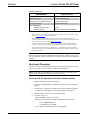
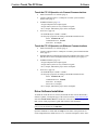
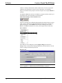
Crestron Touch The PC Driver
Software
Programmer’s Guide
Intended for Version 3.08.34 and Later
This document was prepared and written by the Technical Documentation department at:
Crestron Electronics, Inc.
15 Volvo Drive
Rockleigh, NJ 07647
1-888-CRESTRON
All brand names, product names, and trademarks are the property of their respective owners.
©2004 Crestron Electronics, Inc.
Crestron Touch The PC Driver
Software
Contents
Touch the PC Driver
1
Introduction ............................................................................................................................... 1
Driver Requirements ................................................................................................... 1
Quickstart Procedure ................................................................................................... 2
Driver Software Installation ........................................................................................ 3
Configuring the System ............................................................................................................. 5
PC to Touchpanel Serial Communication ................................................................... 5
PC to Touchpanel Cresnet Communication ................................................................ 7
PC to Touchpanel Ethernet Communication ............................................................... 8
SIMPL Windows Programming .............................................................................................. 13
VT Pro-e Programming ........................................................................................................... 14
Problem Solving ...................................................................................................................... 17
Troubleshooting ........................................................................................................ 17
Further Inquiries........................................................................................................ 18
Future Updates .......................................................................................................... 19
Appendix A – Additional Keyboard Functionality.................................................................. 20
Appendix B – Cable and Wiring Specifications...................................................................... 21
Network Wiring......................................................................................................... 21
Crestron RJ-45 Cabling ............................................................................................. 22
DB9F Adapter and RJ-11 Modular Cable ................................................................. 22
DB9F to RJ-11 Cable Fabrication ............................................................................. 23
Software License Agreement................................................................................................... 24
Return and Warranty Policies.................................................................................................. 26
Merchandise Returns / Repair Service ...................................................................... 26
CRESTRON Limited Warranty ................................................................................ 26
Programmer's Guide - DOC. 5916B
Contents • i
Crestron Touch The PC Driver
Software
Touch the PC Driver
Introduction
The Crestron® Touch the PC Driver, V2 (Touch the PC V2), licensed for use only in
conjunction with the TPS-XVGA/-BV/L Computer Interface Cards, is designed to
enable a Crestron Isys® TPS touchpanel to function as a computer touchscreen
monitor, compatible with Microsoft Windows® 98/XP and Windows 2000/NT.
Touch the PC V2, as described in this manual, should be used instead of any earlier
versions, because it prevents possible confusion between left clicks and double
clicks, and is more compatible with Windows XP.
When you use the touchpanel as a monitor for a computer connected to your
Crestron control system (Cresnet® system), Touch the PC V2 lets you use your
finger on the touchpanel to simulate typical computer mouse click and drag
functions. In operation, use of Touch the PC V2 is similar to using a tablet device
(such as a graphics tablet). For example, touching the cursor and dragging it across
the screen actually creates a selection box and selects displayed items in the path, as
though you had done a left-click-and-drag operation with a regular mouse. The way
to move the cursor using Touch the PC V2 is to first select one of the Touch Action
functions and then perform the action. For example, selecting Touch None only
enables you to move the cursor around the screen—no left- or right-click functions
available. Selecting Touch Left enables you to do a left click (and drag, if desired)
where you touch the screen. Selecting Touch Right enables you to do a right click
(and drag, if desired) where you touch the screen. The buttons associated with these
functions are interlocked.
The touchpanel can connect to the personal computer (PC) running Touch the PC
V2 via a direct serial line, or it can connect to the control system via Cresnet or via
Ethernet, and the control system connects to the PC serially.
The Network/CIP Transmission Symbols are initialized automatically during control
system reboot, eliminating the use of the “todest” and “toformat” commands on the
touchpanel.
Driver Requirements
To program the touchpanel for use with Touch the PC V2, a PC that contains
Crestron VisionTools® Pro-e (VT Pro-e) and SIMPL Windows is required. Refer to
the following table for the requirements of the touchpanel, PC, and Cresnet system.
Programmer’s Guide – DOC. 5916B
Touch the PC Driver • 1
Software
Crestron Touch The PC Driver
Driver Requirements
REQUIREMENT
SPECIFICATION
Touch the PC V2 (UPDD*)
Version 3.08.34 or later1
VisionTools Pro-e
Version 3.2.06 or later1
Crestron Isys® Touchpanel firmware
Version 2.006 or later2, 3
Crestron Database
Version 16.2 or later
PC Requirements:
Available Hard Disc space
5 MB4
Operating System
Microsoft Windows® 98/XP/2000/NT
* Universal Pointer Device Driver
1
The latest versions can be obtained from the Downloads | Software Updates section of the Crestron
website (www.crestron.com). Refer to NOTE below.
2
The TPS-RFGWX and touchpanels with later versions of firmware may include features not
mentioned in this guide. Newer versions of this guide can be obtained from the Downloads | Product
Manuals section of the Crestron website (www.crestron.com).
3
The firmware upgrade files can be obtained from the Downloads | Software Updates section of
Crestron’s website. Crestron recommends that the latest firmware be loaded into the touchpanel.
4
The PC requirements pertain only to the Touch the PC V2. Additional requirements for SIMPL
Windows and/or VT Pro-e are not included. Refer to the documentation supplied with the software
for further information.
NOTE: Crestron software and any files on the website are for Authorized Crestron
dealers and Crestron Authorized Independent Programmers (CAIP) only. New users
may be required to register to obtain access to certain areas of the site (including the
FTP site).
Quickstart Procedure
This section contains brief descriptions of the steps required for utilizing the Touch
the PC V2 program via serial, Cresnet, or Ethernet communication.
NOTE: In the following procedures, if the Touch The PC V2 selection does not
appear, update the Crestron Database to version 16.2 or later.
Touch the PC V2 Operation via Serial Communications
2 • Touch the PC Driver
•
Install Touch the PC V2 software (page 3)
•
Change the touchpanel RS-232 settings to RS-232 port for Touch Output
(page 5)
•
Connect the PC COM port to the RS-232 port of the touchpanel using RJ11 modular cable and adapter, Crestron part number 15556 (page 5)
•
Install touchpanel firmware, version 2.006 or higher
•
In VT Pro-e (page 14):
- Set the RGB object to PAD 1 or PAD 2
- Set the project properties according to the RGB selected PAD area
Select: Touch the PC, V2
Communication via: Serial
- Save, compile, and load the project to the touchpanel
Programmer’s Guide – DOC. 5916B
Crestron Touch The PC Driver
Software
Touch the PC V2 Operation via Cresnet Communications
•
•
•
•
Install Touch the PC V2 software (page 3)
Connect COM port of PC to a COM port of control system with null
modem cable (page 7)
In SIMPL Windows (page 13):
- Assign touchpanel serial output signals
- Assign control system two-way serial driver signals
- Save, compile, and load the project to the touchpanel
In VT Pro-e (page 14):
- Set the RGB object to PAD 1 or PAD 2
- Set the project properties according to the RGB selected PAD area
Select: Touch the PC, V2
Communication via: Cresnet
Serial Join: 1 (example)
Touch the PC V2 Operation via Ethernet Communications
•
Install Touch the PC V2 software (page 3)
•
Connect COM port of PC to COM port of control system with null modem
cable (page 9)
•
Establish Ethernet communications between touchpanel and control system
and add a device ID to touchpanel IP table and control system (page 11)
•
In SIMPL Windows (page 13):
- Assign touchpanel serial output signals
- Assign control system two-way serial driver signals
- Save, compile, and load the project to the touchpanel
•
In VT Pro-e (page 14):
- Set the RGB object to PAD 1 or PAD 2
- Set the project properties according to the RGB selected PAD area
Select: Touch the PC, V2
Communication via: TCP/IP
Serial Join: 1 (example)
Device ID: 3 (example)
- Save, compile, and load the project to the touchpanel
Driver Software Installation
To install the Touch the PC V2 software, download the files from the Downloads |
Software Updates | Touchpanels page of the Crestron website (www.crestron.com).
Search for Touch The PC Driver, V2. This file will create a UPDD folder plus the
PDF version of this programmer’s guide and a Release Notes document.
NOTE: Crestron recommends that the baud rate for both the touchpanel and PC
port be set at the default rate of 9600, N81.
Open the UPDD Driver folder and run setup.exe. The name of the pointer device
can be changed from the default "Device 1" to "Crestron Touchpanel.” In the “Port”
Programmer’s Guide – DOC. 5916B
Touch the PC Driver • 3
Software
Crestron Touch The PC Driver
window, a COM port other than the default COM1 can be selected, to specify the
COM port from which the PC will receive the Touch the PC V2 commands.
Setup.exe will finish with a prompt to restart the computer. The computer MUST be
restarted.
The Windows Start menu will now list UPDD as a program, and the system tray of
the Windows status bar will include icons shown below.
Pointer Device Settings & Event Scheduler Icons
After the system has been configured and programmed as outlined in the rest of this
guide, it can be calibrated (or tested). Right-click the Pointer Device Settings icon
and as shown below, select Calibrate from the Device Manager menu. Select
Device 1 | Normal and calibrate the screen by following the onscreen directions.
Select Calibrate
The COM port can be changed by selecting Adjust settings from the Device
Manager menu. As shown in the following illustration, open the Hardware tab and
choose a COM port from the drop-down list.
Hardware Tab
NOTE: For additional keyboard functionality programmed into the touchpanel,
refer to “Appendix A – Additional Keyboard Functionality” on page 20.
4 • Touch the PC Driver
Programmer’s Guide – DOC. 5916B
Crestron Touch The PC Driver
Software
Configuring the System
The touchpanel may be configured for serial, Cresnet, or Ethernet communication
with the PC that contains the Touch the PC V2 software. TPS tilt touchpanels may
contain a TPS-XVGA or TPS-XVGA-BV card. TPS lectern touchpanels (and TPSTPI user interface) utilize a TPS-XVGAL card. To configure the PC, touchpanel,
and specific TPS-XVGA card, refer to an appropriate section below and or on the
next seven pages. In each configuration, for more information about cabling and
wiring specifications, refer to “Appendix B – Cable and Wiring Specifications” on
page 21.
PC to Touchpanel Serial Communication
For Touch the PC V2 operation using serial communication from the PC to the
touchpanel, refer to the steps below.
1.
At the touchpanel, enter the setup mode. From the Main menu screen,
press Setup, then RS-232. Press RS-232 Port for Touch Output.
2.
Refer to the appropriate (for TPS-XVGA, TPS-XVGA-BV, or TPSXVGAL card) diagrams and tables which follow and make the cable
connections.
Serial Communication #1 - Tilt Touchpanel with TPS-XVGA
A
RGB CABLE
TO
RS-232
PORT
RGB
PORT
AUDIO
NET
COMP
Y
C
COMP
Y
C
+ -S +- S
NTSC/PAL VIDEO
PROFESSIONAL CONTROL PROCESSOR
TPS-IMC
24 Y Z G
NET
PORT
NET (OR
CRESNET)
PORT
TO PANEL
TPS-IMPC
(OR TPS-IMW)
CRESTRON
CRESNET
WIRING
NET/
VI DEO
C
MIC
OUT
B
+- S
COM
PORT
AUDIO
INPUT
PC
TILT TOUCHPANEL
WITH TPS-XVGA
COMMUNICATIONS CABLE
R
L
S + -+- S
VGA
PORT
NET/
VIDEO
PORT
D
NET/
VIDEO
PORT
MENU
BKLT
CRESTRON
PRO
2
CONTROL SYSTEM
REF
SERIAL COMMUNICATION #1 - TILT TOUCHPANEL WITH TPS-XVGA CARD
FROM
TO
CABLING REQUIRED
DEVICE
PORT
CONNECTOR to CONNECTOR
DEVICE
PORT
1
VGA
A
PC
2
COM
B
PC
3
NET
C
Control System
4
NET/VIDEO
D
TPS-IMPC
DB-15, male
DB-15, male
Touchpanel
RGB
DB-9, female
RJ-11, 6-pin
Touchpanel
RS-232
4-wire Cresnet
4-wire Cresnet
TPS-IMPC
NET
RJ-45, 10-pin
RJ-45, 10-pin
Touchpanel
NET/VIDEO
1 Standard stranded VGA monitor cable.
2 This connection can be made via a modular RJ-11 cable (supplied with touchpanel) and DB9F to RJ-11 adapter.
3 During serial communications, the control system and Cresnet wiring are required for touchpanel basic
functionality and operating power.
4 A 15-foot NET/VIDEO cable is supplied with the TPS-IMPC.
Programmer’s Guide – DOC. 5916B
Touch the PC Driver • 5
Software
Crestron Touch The PC Driver
Serial Communication #2 - Tilt Touchpanel with TPS-XVGA-BV
TPS-IMC-BV
RGB
PORT
Z G
NET
24 Y
COAX
AUDIO
BAL
TPS-IMC-BV
24VDC
2. 0A
CRESTRON
B
RG B
B ALANCED
VIDEO
TO PANEL
C
COM
PORT
NTSC/P AL VIDEO
NET PORT
RGB
PORT
NET/
VIDEO
C OM P
Y
PC
COMM. CABLE
AUDIO
INP UT
AUDI O
INP UT
R GB
VGA
PORT
R
L
S + - +- S
MIC
OUT
RGB CABLE
+- S
A
C
E
D
CRESNET
WIRING
NET (OR
CRESNET)
PORT
PROFESSIONAL CONTROL PROCESSOR
TILT TOUCHPANEL
WITH TPS-XVGA-BV
NET/VIDEO
PORT
TO NET/
VIDEO
PORT
RGB
PORT
RS-232
PORT
MENU
BKLT
CRESTRON
PRO
2
CONTROL SYSTEM
SERIAL COMMUNICATION #2 - TILT TOUCHPANEL WITH TPS-XVGA-BV CARD
FROM
CABLING REQUIRED
TO
DEVICE
PORT
CONNECTOR to CONNECTOR
DEVICE
PORT
REF
1
VGA
A
PC
2
RGB
B
TPS-IMC-BV
3
COM
C
PC
4
NET
D
Control System
2
E
TPS-IMC-BV NET/VIDEO
DB-15, male
DB-15, male
TPS-IMC-BV
RJ-45, 10-pin
RJ-45, 10-pin
Touchpanel
RGB
RGB
DB-9, female
RJ-11, 6-pin
Touchpanel
RS-232
4-wire Cresnet
4-wire Cresnet
TPS-IMC-BV
NET
RJ-45, 10-pin
RJ-45, 10-pin
Touchpanel
NET/VIDEO
1 Standard stranded VGA monitor cable.
2 These connections (ref B & E) can be made with the 15-foot Triamese cable supplied with the TPS-IMC-BV.
3 This connection can be made via a modular RJ-11 cable (supplied with touchpanel) and DB9F to RJ-11 adapter.
4 During serial communications, the control system and Cresnet wiring are required for touchpanel basic
functionality and operating power.
Serial Communication #3 - Lectern Touchpanel with TPS-XVGAL
A
LECTERN TOUCHPANEL
(OR TPS-TPI) WITH
TPS-XVGAL
RGB CABLE
VGA
PORT
PC
COMMUNICATIONS CABLE
COM
PORT
B
C
CRESNET WIRING
NET (OR
CRESNET)
PORT
PROF ESSIONAL C ONT ROL PROCESSOR
TO
RS-232
PORT
RGB INPUT
PORT
NET
PORT
ME NU
BK LT
CRESTRON
PRO
2
CONTROL SYSTEM
SERIAL COMMUNICATION #3 - LECTERN TOUCHPANEL WITH TPS-XVGAL CARD
FROM
CABLING REQUIRED
TO
REF
DEVICE
PORT
CONNECTOR to CONNECTOR
DEVICE
PORT
1
VGA
DB-15, male
BNC-5, male
Touchpanel
RGB
A
PC
2
COM
DB-9,
female
RJ-11,
6-pin
Touchpanel
RS-232
B
PC
3
NET
4-wire Cresnet
4-wire Cresnet
Touchpanel
NET
C
Control System
1 A standard stranded VGA monitor cable with DB15F to BNC-5 adapter is required. Both are commercially
available.
2 This connection can be made via a modular RJ-11 cable (supplied with touchpanel) and DB9F to RJ-11 adapter.
3 During serial communications, the control system and Cresnet wiring are required for touchpanel basic
functionality and operating power.
3.
6 • Touch the PC Driver
Proceed to “VT Pro-e Programming” that begins on page 14.
Programmer’s Guide – DOC. 5916B
Crestron Touch The PC Driver
Software
PC to Touchpanel Cresnet Communication
For Touch the PC V2 operation using Cresnet communication to the touchpanel,
refer to the steps below.
1.
Refer to the appropriate (for TPS-XVGA, TPS-XVGA-BV, or TPSXVGAL card) diagrams and tables that follow and make the cable
connections.
Cresnet Communication #1 - Tilt Touchpanel with TPS-XVGA
A
RGB CABLE
COMM. CABLE
VGA
PORT
COM
PORT
PC
B
CONTROL
SYSTEM
COM
PORT
PROFESSIO NAL CO NTRO L PROCESSOR
MENU
BKLT
2
TILT TOUCHPANEL
WITH TPS-XVGA
D
AUDIO
RGB
PORT
C
COMP
Y
C
+- S +- S
NTSC/PAL VIDEO
MIC
OUT
NET/
VIDEO
COMP
Y
+-S
NET
C
TPS-IMC
24 Y Z G
NET
PORT
CRESTRON
CRESNET
WIRING
TO PANEL
TPS-IMPC
(OR TPS-IMW)
AUDIO
INPUT
PRO
NET (OR
CRESNET)
PORT
NET/VIDEO
PORT
R
L
S + - +- S
CRESTRON
NET/VIDEO
PORT
REF
A
CRESNET COMMUNICATION #1 - TILT TOUCHPANEL WITH TPS-XVGA CARD
FROM
CABLING REQUIRED
TO
DEVICE
PORT
CONNECTOR to CONNECTOR
DEVICE
PORT
1
VGA
PC
2
COM
B
PC
NET
C
Control System
3
NET/VIDEO
D
TPS-IMPC
DB-15, male
DB-15, male
Touchpanel
RGB
DB-9, female
4-wire Cresnet
DB-9, female
4-wire Cresnet
Control System
TPS-IMPC
COM
NET
RJ-45, 10-pin
RJ-45, 10-pin
Touchpanel
NET/VIDEO
1 Standard stranded VGA monitor cable.
2 Standard null modem serial cable.
3 A 15-foot NET/VIDEO cable is supplied with the TPS-IMPC.
Cresnet Communication #2 - Tilt Touchpanel with TPS-XVGA-BV
A
RGB CABLE
VGA
PORT
PC
COMM. CABLE
COM
PORT
C
COM
PORT
PROFESSIONAL CONTROL PROCESSOR
CONTROL
SYSTEM
MENU
BKLT
PRO
2
TPS-IMC-BV
RGB
PORT
COAX
AUDIO
INPUT
AUDIO
INPUT
NET
24 Y Z G
TPS-IMC-BV
24VDC
2.0 A
CRESTRON
AUDIO
BAL
BALANCED
VIDEO
RG B
C
NTSC/PAL V IDEO
TO PANEL
COMP
Y
D
NET
PORT
TILT TOUCHPANEL
WITH TPS-XVGA-BV
B
RGB
PORT
RGB
PORT
NET /
VIDEO
RGB
CRESNET
WIRING
R
L
S +-+ - S
MIC
OUT
NET (OR
CRESNET)
PORT
+- S
CRESTRON
NET/VIDEO
PORT
E
NET/VIDEO
PORT
Programmer’s Guide – DOC. 5916B
Touch the PC Driver • 7
Software
Crestron Touch The PC Driver
CRESNET COMMUNICATION #2 - TILT TOUCHPANEL WITH TPS-XVGA-BV CARD
FROM
CABLING REQUIRED
TO
REF
DEVICE
PORT
CONNECTOR to CONNECTOR
DEVICE
PORT
1
VGA
DB-15, male
DB-15, male
TPS-IMC-BV
RGB
A
PC
2
RGB
RJ-45, 10-pin
RJ-45, 10-pin
Touchpanel
RGB
B
TPS-IMC-BV
3
COM
C
PC
NET
D Control System
2
E
TPS-IMC-BV NET/VIDEO
DB-9, female
4-wire Cresnet
DB-9, female
4-wire Cresnet
Control System
TPS-IMC-BV
COM
NET
RJ-45, 10-pin
RJ-45, 10-pin
Touchpanel
NET/VIDEO
1 Standard stranded VGA monitor cable.
2 These connections (ref B & E) can be made with the 15-foot Triamese cable supplied with the TPS-IMC-BV if an
audio connection is also desired.
3 Standard null modem serial cable.
Cresnet Communication #3 - Lectern Touchpanel with TPS-XVGAL
A
RGB CABLE
VGA
PORT
PC
COMM. CABLE
COM
PORT
B
COM
PORT
PROFESSIONAL CONTR OL PROC ESSOR
CONTROL
SYSTEM
LECTERN TOUCHPANEL
(OR TPS-TPI) WITH
TPS-XVGAL
MENU
B KL T
CRESTRO N
PRO
2
NET (OR
CRESNET)
PORT
RGB
INPUT
PORT
CRESNET
WIRING
C
NET
PORT
CRESNET COMMUNICATION #3 - LECTERN TOUCHPANEL WITH TPS-XVGAL CARD
FROM
CABLING REQUIRED
TO
REF
DEVICE
PORT
CONNECTOR to CONNECTOR
DEVICE
PORT
1
VGA
DB-15, male
BNC-5, male
Touchpanel
RGB
A
PC
B
C
2
PC
Control System
COM
NET
DB-9, female
4-wire Cresnet
DB-9, female
4-wire Cresnet
Control System
Touchpanel
COM
NET
1 A standard stranded VGA monitor cable with DB15F to BNC-5 adapter is required. Both are commercially
available.
2 Standard null modem serial cable.
2.
Proceed to “VT Pro-e Programming” that begins on page 14.
PC to Touchpanel Ethernet Communication
For Touch the PC V2 operation using Ethernet communication from the PC to the
touchpanel, refer to the following two sections, “Cabling Connections” and
“Ethernet Setup.”
NOTE: To connect the LAN port on the control system and the LAN port on the
touchpanel base directly instead of through an Ethernet hub, use an Ethernet
crossover cable (not supplied).
8 • Touch the PC Driver
Programmer’s Guide – DOC. 5916B
Crestron Touch The PC Driver
Software
NOTE: A Crestron TPS-ENET or TPS-ENETL Ethernet expansion card must be
installed in the touchpanel to enable Ethernet communication. For further
information, refer to the TPS-ENET or TPS-ENETL Operations & Installation
Guide (Doc. 6016 or 6013, respectively). The latest revisions can be obtained from
the Downloads | Product Manuals section of the Crestron website
(www.crestron.com). New users are required to register to obtain access to the FTP
site.
NOTE: The Crestron control system must contain an Ethernet expansion card to
enable Ethernet communication. On CNX Generation control systems, the port may
be labeled LAN or LAN/DPA. On 2-Series control systems, the port may be labeled
LAN A or LAN B. For further information about CNX Generation Ethernet cards,
refer to the CNXENET or CNXENET+ Operations & Installation Guide (Doc. 8129
or 8153, respectively). For further information about 2-Series Ethernet cards, refer to
the C2ENET-1/-2 Operations & Installation Guide (Doc. 5962). The latest revisions
can be obtained from the Downloads | Product Manuals section of the Crestron
website (www.crestron.com).
Cabling Connections
For Touch the PC V2 operation using Ethernet communication with the PC, refer to
the steps below.
1.
Refer to the appropriate (for TPS-XVGA, TPS-XVGA-BV, or TPSXVGAL card) diagrams and tables which follow and make the cable
connections.
Ethernet Communication #1 - Tilt Touchpanel with TPS-XVGA
A
RGB CABLE
VGA
PORT
PC
POWER
PACK
COMM. CABLE
COM
PORT
B
COM
PORT
PROFESSIO NAL CONTRO L PRO CESSOR
CONTROL
SYSTEM
M ENU
TILT TOUCHPANEL
WITH TPS-XVGA
B KLT
C RESTR ON
PRO
2
LAN
PORT
C
TO
RGB
PORT
ETHERNET
WIRING
ETHERNET
ROUTER/HUB
REF
A
1
E
D
24VDC
2.0A
PORT
LAN
PORT
ETHERNET COMMUNICATION #1 - TILT TOUCHPANEL WITH TPS-XVGA CARD
FROM
CABLING REQUIRED
TO
DEVICE
PORT
CONNECTOR to CONNECTOR
DEVICE
PORT
PC
2
B
PC
3
C
Control System
3
D
Ethernet / Hub
4
E
PWR. PACK
VGA
DB-15, male
DB-15, male
Touchpanel
RGB
COM
DB-9, female
DB-9, female
Control System
COM
LAN
RJ-45, 8-pin
RJ-45, 8-pin
Ethernet / Hub
na
na
RJ-45, 8-pin
RJ-45, 8-pin
Touchpanel
LAN
Touchpanel
24VDC 2A
na
na
1 Standard stranded VGA monitor cable.
2 Standard null modem serial cable.
3 Standard Ethernet cables (ref C & D).
4 Power pack (PW-2420RU) is NOT required if power is supplied via Cresnet.
Programmer’s Guide – DOC. 5916B
Touch the PC Driver • 9
Software
Crestron Touch The PC Driver
Ethernet Communication #2 - Tilt Touchpanel with TPS-XVGA-BV
A
RGB
PORT
COAX
AUDIO
RGB
TO P ANEL
BAL
TPS- IMC-BV
NET
24 Y Z G
CRESTRON
24VDC
2.0A
PROFESSIONAL CONTROL PROCESSOR
BALANCED
V IDEO
CONTROL
SYSTEM
COM
PORT
C
C
NTSC/PAL VIDEO
COM
PORT
RGB
PORT
NET /
VID EO
COMP
Y
PC
24VDC
2.0A
PORT
AUDIO
INPUT
AUDIO
INP UT
R GB
VGA
PORT
COMM. CABLE
R
L
S + - +- S
MIC
OUT
TPS-IMC-BV
+- S
RGB CABLE
MENU
G
BKLT
CRESTRON
PRO
2
LAN
PORT
POWER
PACK
F
D
B
NET/
VIDEO
PORT
ETHERNET
WIRING
TO
NET/
VIDEO
PORT
TILT TOUCHPANEL
WITH TPS-XVGA-BV
RGB
PORT
ETHERNET
ROUTER/HUB
E
LAN
PORT
ETHERNET COMMUNICATION #2 - TILT TOUCHPANEL WITH TPS-XVGA-BV CARD
FROM
CABLING REQUIRED
TO
REF
DEVICE
PORT
CONNECTOR to CONNECTOR
DEVICE
PORT
1
VGA
DB-15, male
DB-15, male
TPS-IMC-BV
RGB
A
PC
2
RGB
RJ-45, 10-pin
RJ-45, 10-pin
Touchpanel
RGB
B
TPS-IMC-BV
3
COM
C
PC
4
LAN
D
Control System
4
na
E
Ethernet / Hub
5
na
F
PWR. PACK
2
G
TPS-IMC-BV NET/VIDEO
DB-9, female
DB-9, female
Control System
RJ-45, 8-pin
RJ-45, 8-pin
Ethernet / Hub
na
RJ-45, 8-pin
RJ-45, 8-pin
Touchpanel
LAN
na
RJ-45, 10-pin
RJ-45, 10-pin
COM
TPS-IMC-BV
24VDC 2A
Touchpanel
NET/VIDEO
1 Standard stranded VGA monitor cable.
2 These connections (ref B & G) can be made with the 15-foot Triamese cable supplied with the TPS-IMC-BV.
3 Standard null modem serial cable.
4 Standard Ethernet cables (ref D & E).
5 Power pack is NOT required if control system is connected to touchpanel via Ethernet AND Cresnet.
10 • Touch the PC Driver
Programmer’s Guide – DOC. 5916B
Crestron Touch The PC Driver
Software
Ethernet Communication #3 - Lectern Touchpanel with TPS-XVGAL
A
RGB CABLE
VGA
PORT
PC
COMM. CABLE
COM
PORT
B
COM
PORT
PROFESSIONAL CONTR OL PROC ESSOR
CONTROL
SYSTEM
LECTERN TOUCHPANEL
(OR TPS-TPI) WITH
TPS-XVGAL
ME NU
B KL T
CRESTRO N
PRO
LAN
PORT
NET (OR
CRESNET)
PORT
C
D
ETHERNET
WIRING
ETHERNET
ROUTER/HUB
2
CRESNET WIRING
RGB
INPUT
PORT
TO
NET
PORT
LAN
PORT
E
ETHERNET COMMUNICATION #3 - LECTERN TOUCHPANEL WITH TPS-XVGAL CARD
TO
FROM
CABLING REQUIRED
REF
DEVICE
PORT
CONNECTOR to CONNECTOR
DEVICE
PORT
1
VGA
DB-15, male
BNC-5, male
Touchpanel
RGB
A
PC
2
B
PC
3
C
Control System
4
D
Control System
4
E
Ethernet / Hub
COM
DB-9, female
DB-9, female
Control System
COM
NET
4-wire Cresnet
4-wire Cresnet
Touchpanel
NET
LAN
RJ-45, 8-pin
RJ-45, 8-pin
Ethernet / Hub
na
na
RJ-45, 8-pin
RJ-45, 8-pin
Touchpanel
LAN
1 A standard stranded VGA monitor cable with DB15F to BNC-5 adapter is required. Both are commercially
available.
2 Standard null modem serial cable.
3 Cresnet wiring is required for touchpanel operating power only.
4 Standard Ethernet cables (ref D &E).
2.
Proceed to “Ethernet Setup” which follows.
Ethernet Setup
Ethernet devices that are addressed by the control system may have their IP IDs set
either in the SIMPL Windows program or through the Crestron Viewport using a
PC. Ultimately, each IP ID is converted into an actual IP address through an IP table
that exists inside the control system. The IP table is an internal list of information
that contains the IP IDs and associated IP addresses of all Ethernet devices in the
program. The IP table is accessed by the control system to identify and locate
Ethernet devices, for purposes of communication. Follow this procedure to add the
Touch The PC Driver, V2 software to the IP table of the touchpanel.
Programmer’s Guide – DOC. 5916B
1.
Using the Crestron Viewport, (Remote | TCP/IP | Connect or Remote
| Remote Console | Connect) establish communication with the
touchpanel.
2.
As shown on the next page, use the ipt (IPTABLE) command to
display the current IP table for the CIP interface on the touchpanel.
Touch the PC Driver • 11
Software
Crestron Touch The PC Driver
IP Table
3.
As shown below, using the addm (ADDMASTER) command to add a
CIP node to the master list of the touchpanel, enter the information in
the following format with spaces (no period or underscore) between the
entries: CIP ID from SIMPL Windows (example of 4 is shown), IP
address of touchpanel (example of 132.149.010.147 is shown), and
Device ID (example of 4 is shown). To remove an IP address, use the
REMM command.
NOTE: The Device ID of the Touch the PC V2 does not have to match the CIP
ID. It will also be used in step 6 of “VT Pro-e Programming” that begins on page 14.
4.
As shown below, use the ipt command to display the updated IP table
on the touchpanel.
Updated IP Table
5.
12 • Touch the PC Driver
Proceed to “SIMPL Windows Programming” that begins on the next
page.
Programmer’s Guide – DOC. 5916B
Crestron Touch The PC Driver
Software
SIMPL Windows Programming
With a Cresnet or Ethernet connection (serial connection does NOT require SIMPL
Windows programming), it is necessary to create a SIMPL Windows program to
route the data. In the Configuration Manager, add the appropriate Plug-in Control
Card or DPA Module to the control system and drag in the Cresnet or Ethernetenabled touchpanel. (The entries in the IP table, for IP ID and IP address, must be
set the same as for standard operation of the touchpanel on Cresnet or Ethernet.)
Configure the devices as usual.
In the Program Manager, route the output string in the touchpanel definition to an
RS-232 COM port as follows:
1.
Open a Detail View for the touchpanel, and click the Serial button.
Specify a signal name for a serial output (mouse_cmds on <text-i1> is
shown below as an example).
NOTE: As shown, Serial Join 1 for <text-i1> will be used in step 6 of “VT Pro-e
Programming” that begins on page 14.
Detail View of Serial Signals for the Touchpanel in SIMPL Windows’
Programming Manager
2.
Open a Detail View of the RS-232 COM port from the appropriate slot
of the Central Control Module. As shown in the following illustration,
type or drag the specified string name to the <tx$> input. (As shown,
Port A was selected.)
Detail View of Serial Signals for the RS-232 COM Port in SIMPL Windows’
Programming Manager
3.
Programmer’s Guide – DOC. 5916B
In the SIMPL Windows Configuration Manager Tree View, open the
COM port slot, and double-click Port A. Select the Serial Settings tab
and make sure that the settings are as shown in the following figure.
Touch the PC Driver • 13
Software
Crestron Touch The PC Driver
Device Settings of the RS-232 COM Port in SIMPL Windows’ Configuration
Manager
4.
Compile and upload the SIMPL Windows program to the control
system.
5.
Proceed to “VT Pro-e Programming” that follows.
VT Pro-e Programming
The Touch the PC V2 and PC configuration must be programmed in VT Pro-e and
the project uploaded to the touchpanel. This entails the following steps, which are
explained in detail in this section.
An RGB object must be created on a page or subpage. To create an RGB object,
perform the following steps.
1.
In VT Pro-e, open the touchpanel project.
2.
As shown below, make sure that the project window is the active
window.
Project Window Active
3.
14 • Touch the PC Driver
As shown in the following image, right-click on the project and select
Properties.
Programmer’s Guide – DOC. 5916B
Crestron Touch The PC Driver
Software
Select Project Properties
4.
In the “Project Properties” window, select the Pad Area tab.
5.
Refer to the diagram below. In the Type drop-down list of the desired
Pad Area, select Touch The PC V2 (Pad Area 1 is shown).
NOTE: If the Touch The PC V2 selection does not appear, update the Crestron
Database to version 16.2 or later.
Select Touch The PC V2 in Pad Area 1
6.
Programmer’s Guide – DOC. 5916B
In the Communication via drop-down list of the “Project Properties”
window, select either Serial or Cresnet or TCP/IP (for Ethernet
operation) and continue with this step.
Touch the PC Driver • 15
Software
Crestron Touch The PC Driver
•
6a. If Serial is selected, proceed to step 7 below.
•
6b. If Cresnet is selected, select the serial join number (specified
during step 1 of “SIMPL Windows Programming” that begins on
page 13) to reference the assigned touchpanel serial output from
the Serial Join drop-down list.
•
6c. If TCP/IP is selected, select the serial join number (specified
during step 1 of “SIMPL Windows Programming” that begins on
page 13) to reference the assigned touchpanel serial output from
the Serial Join drop-down list. Then select the desired device ID
from the Device ID drop-down list (specified during step 3 of “VT
Pro-e Programming” that begins on page 14.)
7.
In the “Project Properties” window, click OK.
8.
Open (or create) a page or subpage and select Draw | RGB Window
(or from the Objects Drawing toolbar, click the Draw RGB Window
button).
9.
Position the cursor on the page and drag out a box of the desired size.
10. Double-click the RGB window to display “RGB Video Properties”
window and set parameters, as with any other VT Pro-e object.
11. In the “RGB Video Properties” window, select the Design tab.
NOTE: The bigger the window, the less noticeable will be any calibration error
NOTE: Pad 2 may be used for a second computer, an alternate connection, or a
Boeckeler Pointmaker® Video Marker telestrator, a video annotation device by
Boeckeler Instruments (www.pointmaker.com). For further information, refer to the
latest revision of Pointmaker® Telestrator Integration Guide (Doc. 5929). This
document can be obtained from the Downloads | Product Manuals section of the
Crestron website (www.crestron.com). New users are required to register in order to
obtain access to the FTP site.
“RGB Video Properties” Window
NOTE: If desired, buttons with special reserved join numbers to specify additional
mouse and computer functions may be created. To create the buttons, refer to
“Appendix A – Additional Keyboard Functionality” on page 20.
16 • Touch the PC Driver
Programmer’s Guide – DOC. 5916B
Crestron Touch The PC Driver
Software
12. Save, compile, and load the project to the touchpanel.
13. The Touch the PC V2 is ready for operation.
Problem Solving
Troubleshooting
The table below and continued on the next page provides corrective action for
possible trouble situations. If further assistance is required, please contact a Crestron
customer service representative.
Touch the PC V2 Troubleshooting
POSSIBLE
CAUSE(S)
TROUBLE
CORRECTIVE ACTION
PC hangs or
Some PCs
displays a blue
(particularly with
screen upon reboot. Windows 95) can
have problems with
the "RunOnce"
process upon
loading a serial or
mouse driver.
Make sure that there are no more than
three mouse drivers (including the
Crestron Touch The PC V2 driver)
installed on the PC at one time.
There is no cursor
movement.
Uninstall then re-install Touch The PC
V2 driver.
Touch The PC V2
driver is not properly
installed.
Touch The PC V2
driver is disabled.
Right-click on system tray icon and
select Enabled. (Enabled will be
checked not X'ed.)
Non-Microsoft serial Disable the conflicting driver. (It may be
driver does not work necessary to uninstall & re-install Touch
with Touch The PC The PC V2 driver.)
V2 driver.
Touchpanel was not For Serial Configuration:
initialized properly. 1. Check that the Pad Properties
settings in VT Pro-e are correct.
2. Use the "RS-232 touch output"
command (touchout) to reserve the
RS-232 port for touch screen output type RS232 touchout and press
<ENTER>. Verify the setting - type
RS232 and press <ENTER>. This
should display “Current RS-232
Mode: TouchOutput.” * Reboot
touchpanel.
For Cresnet or Ethernet Configuration:
Check that the Pad Properties settings
in VT Pro-e are correct.
(continued on next page)
Programmer’s Guide – DOC. 5916B
Touch the PC Driver • 17
Software
Crestron Touch The PC Driver
Touch the PC V2 Troubleshooting (continued)
POSSIBLE
CORRECTIVE ACTION
CAUSE(S)
Touchpanel is not
PC serial port not From the Crestron Viewport, confirm
generating packets operating properly. that serial port is operational and
(no cursor
packets are input to PC.
movement).
1. Double-click the system tray icon
to display the "Pointer Device
Properties" window and select the
Status tab.
2. Confirm that Status window
shows 0 totals for all errors.
TROUBLE
If errors > 0, verify baud rate of PC
matches touchpanel baud rate
(9600, N81).
3. Re-initialize the driver: Select
Advanced tab, move the bottom
scroll bar slightly, and click Apply or
run Calibrate from "Pointer Device
Properties" window. Re-check
number errors.
PC is sluggish or
PC parameter for
In Control Panel, double-click Mouse to
double-clicks
double-click speed open "Mouse Properties" window. Select
Buttons tab and adjust double-click
unintentionally.
has changed.
speed.
Reboot PC.
PC does not
PC "locked".
perform mouse
Touchpanel
From the Viewport, select Remote |
functions (left-click, "locked".
Remote Console | Connect and enter
right-click, doubleRESTORE command.
click).
If changed, parameters cannot be reset.
Touch The PC V2
Uninstall then re-install Touch The PC
driver parameters
have been changed. V2 driver.
*
If display is not correct, type restore to reset factory defaults (including serial
port parameter) then type RS232 touchout. If display is not correct after
verification, refer to “Further Inquiries” on page 18 and contact Crestron
customer service.
Further Inquiries
If, after reviewing this Programmer’s Guide, you cannot locate specific information
or have questions, please take advantage of Crestron's award winning customer
service team in your area. Dial one of the following numbers.
18 • Touch the PC Driver
•
In the US and Canada, call Crestron's corporate headquarters at
1-888-CRESTRON [1-888-273-7876].
•
In Europe, call Crestron International at +32-15-50-99-50.
•
In Asia, call Crestron Asia at +852-2341-2016.
•
In Latin America, call Crestron Latin America at +5255-5093-2160.
•
In Australia and New Zealand, call Crestron Control Solutions at
+61-2-9737-8203.
Programmer’s Guide – DOC. 5916B
Crestron Touch The PC Driver
Software
You can also log onto the online help section of the Crestron website
(www.crestron.com) to ask questions about Crestron products. First-time users will
need to establish a user account to fully benefit from all available features.
Future Updates
As Crestron improves functions, adds new features, and extends the capabilities of
the Touch the PC V2, additional information and programming examples may be
made available as manual updates. These updates are solely electronic and serve as
intermediary supplements prior to the release of a complete technical documentation
revision.
Check the Crestron website (www.crestron.com) periodically for manual update
availability and its relevance. Updates are available from the Downloads | Product
Manuals section and are identified as an “Addendum” in the Download column.
Programmer’s Guide – DOC. 5916B
Touch the PC Driver • 19
Software
Crestron Touch The PC Driver
Appendix A – Additional Keyboard Functionality
VT Pro-e button objects can simulate up to fifteen computer and mouse functions,
using special reserved joins. The following example is for a “scroll up” button.
1.
Open the RGB page in VT Pro-e, create a button object and position
and size it on the page. Set parameters, as usual.
2.
In the “Button Properties” window, select Digital Press Join, click
Reserved Join, select Sys Touchout Action 2 from the drop-down
list, and click OK as shown below.
Reserved Join Number Field of the “Button Properties” Window
The following table lists all the available actions that can be assigned to a button,
using the reserved Digital Press Join selection of the “Button Properties” window.
Mouse Action Reserved Join Numbers
ACTION
RESERVED JOIN NUMBERS
PAD AREA 1
PAD AREA2
Code 0001
Touchout Action 1
Touchout Action 1B
Scroll Up*
Touchout Action 2
Touchout Action 2B
Scroll Down*
Touchout Action 3
Touchout Action 3B
Escape Key
Touchout Action 4
Touchout Action 4B
Tab Key
Touchout Action 5
Touchout Action 5B
Backspace Key
Touchout Action 6
Touchout Action 6B
Enter Key
Touchout Action 7
Touchout Action 7B
Spacebar Key
Touchout Action 8
Touchout Action 8B
Insert Key
Touchout Action 9
Touchout Action 9B
Delete Key
Touchout Action A
Touchout Action AB
Home Key
Touchout Action B
Touchout Action BB
End Key
Touchout Action C
Touchout Action CB
Page Up Key
Touchout Action D
Touchout Action DB
Page Down Key
Touchout Action E
Touchout Action EB
Custom (generates a “!” character)
Touchout Action F
Touchout Action FB
*Since scroll functions are not natural Windows functions, not all applications will understand
them correctly.
NOTE: Analog join number 17204 defines the default action of any press on pad
area 1; join number 17210 defines the default action of any press on pad area 2. If its
value is 0, there will be no click action, only cursor movement. If its value is 1, there
is a left-click action for each press. If its value is 2, there is a right-click action for
each press. If the default action is set to left-click, pressing on the touchpanel twice
will provide double-click capabilities.
20 • Touch the PC Driver
Programmer’s Guide – DOC. 5916B
Crestron Touch The PC Driver
Software
Appendix B – Cable and Wiring Specifications
Network Wiring
CAUTION: Use only Crestron power supplies for Crestron equipment. Failure to
do so could cause equipment damage or void the Crestron warranty.
CAUTION: Provide sufficient power to the system. Insufficient power can lead to
unpredictable results or damage to the equipment. Please use the Crestron Power
Calculator to help calculate how much power is needed for the system.
http://www.crestron.com/dealer-tech_resources/power_calculator.asp
NOTE: When installing network wiring, refer to the latest revision of the wiring
diagram(s) appropriate for your specific system configuration, available from the
Downloads | Product Manuals | Wiring Diagrams section of the Crestron website
(www.crestron.com).
When calculating the wire gauge for a particular Cresnet run, the length of the run
and the power factor of each network unit to be connected must be taken into
consideration. If Cresnet units are to be daisy-chained on the run, the power factor of
each unit to be daisy-chained must be added together to determine the power factor
of the entire chain. If the unit is a home-run from a Crestron system power supply
network port, the power factor of that unit is the power factor of the entire run. The
length of the run in feet and the power factor of the run should be used in the
resistance equation below to calculate the value on the right side of the equation.
Resistance Equation
R < 40,000
L x PF
Where: R = Resistance (refer to table below).
L = Length of run (or chain) in feet.
PF = Power factor of entire run (or chain).
The required wire gauge should be chosen such that the resistance value is less than
the value calculated in the resistance equation. Refer to the following table.
Wire Gauge Values
RESISTANCE
WIRE GAUGE
4
6
10
15
13
8.7
16
18
20
22
Doubled CAT5
Tripled CAT5
NOTE: All Cresnet wiring must consist of two twisted pairs. One twisted pair is the
+24V conductor and the GND conductor, and the other twisted pair is the Y
conductor and the Z conductor.
NOTE: When daisy-chaining Cresnet units, strip the ends of the wires carefully to
avoid nicking the conductors. Twist together the ends of the wires that share a pin on
the network connector, and tin the twisted connection. Apply solder only to the ends
of the twisted wires. Avoid tinning too far up the wires or the end becomes brittle.
Programmer’s Guide – DOC. 5916B
Touch the PC Driver • 21
Software
Crestron Touch The PC Driver
Insert the tinned connection into the Cresnet connector and tighten the retaining
screw. Repeat the procedure for the other three conductors.
Crestron RJ-45 Cabling
CAUTION: The 15-foot, 10-pin RJ-45 connector cable supplied by Crestron is a
custom cable and is the only one that should be used. The end of the cable has a
metal shield that is required to protect the equipment. Using non-Crestron cables will
result in damage to the product. Other cables lengths are available from Crestron.
NOTE: When connecting the touchpanel to the interface module, do not confuse
the 8-pin audio cable with the 10-pin net/video cable.
A 15-foot, RJ-45, 10-position, NET/VIDEO cable is supplied with the TPS-IMPC.
The cable is available to provide optional lengths; part number TPS-CBL-3 is the 3foot version, TPS-CBL-6 is a 6-foot version, and TPS-CBL-9 is the 9-foot version.
Contact Crestron customer service for further information.
A 15-foot, RJ-45, Siamese (two cables joined together) cable is available from
Crestron. The cable minimizes the number of individual cables attached to the
touchpanel. The Siamese cable consists of a 10-position NET/VIDEO cable, an 8position AUDIO cable and is available to provide optional lengths. Part number
TPS-CBL-S3 is the 3-foot version, TPS-CBL-S6 is a 6-foot version, and TPS-CBLS9 is the 9-foot version. This cable may be used for any system configuration when
NET/VIDEO and AUDIO connections are necessary. Contact Crestron customer
service for further information.
A 15-foot, RJ-45, Triamese (three cables joined together) cable is supplied with the
TPS-IMC-BV. The cable minimizes the number of individual cables attached to the
touchpanel. The Triamese cable consists of a 10-position NET/VIDEO cable, 10position RGB video cable, an 8-position AUDIO cable and is available to provide
optional lengths. Part number TPS-CBL-T3 is the 3-foot version, TPS-CBL-T6 is a
6-foot version, and TPS-CBL-T9 is the 9-foot version. This cable may be used for
any system configuration when NET/VIDEO, RGB video and AUDIO connections
are necessary. Contact Crestron customer service for further information.
DB9F Adapter and RJ-11 Modular Cable
To program the touchpanel for serial communication at the RS-232 port, a DB9F to
RJ-11 adapter and 6-conductor modular (RJ-11) cable is required. These
components are not supplied but are part of the SmarTouch Programming Kit
(Crestron part number ST-PK). If already available, use these components. If
needed, contact Crestron customer service. A cable assembly that consists of a DB9F
to RJ-11 adapter and modular cable is also available from Crestron. Contact Crestron
customer service for part number STCP-502.
The DB9F to RJ-11 adapter is available commercially or contact Crestron customer
service for part number 15556. For RJ-11 modular cable specifications, refer to the
latest revision of the Crestron Network Modular Cable Requirements (Doc. 5682).
This document is available from the Downloads | Product Manuals section of the
Crestron website (www.crestron.com).
22 • Touch the PC Driver
Programmer’s Guide – DOC. 5916B
Crestron Touch The PC Driver
Software
DB9F to RJ-11 Cable Fabrication
In the event that modular cables or the DB9F to RJ-11 adapter is not readily
available, the table and diagram below are provided so that the cable can be
fabricated. All parts are commercially available.
RJ-11 Modular Cable Pinouts
PIN
DESCRIPTION
PIN
DESCRIPTION
1
2
3
CTS (Clear to Send)
GND
RxD (Received Data)
4
5
6
TxD (Transmitted Data)
RTS (Request to Send)
Not Connected
PC to Touchpanel Cable Specification
TO PC
COM PORT
REAR VIEW OF
CONNECTOR
1
2
3
4
5
6
2
3
5
7
8
9
7
8
TO RS-232
PORT
1
2
3
4
5
6
CTS
GND
RxD
TxD
RTS
n/c
PART #
AWC10152-A
1
PART #
641337
(9-PIN FEMALE)
PART #
748047-1
Programmer’s Guide – DOC. 5916B
Touch the PC Driver • 23
Software
Crestron Touch The PC Driver
Software License Agreement
This License Agreement (“Agreement”) is a legal contract between you (either an individual or a single business entity) and
Crestron Electronics, Inc. (“Crestron”) for software referenced in this guide, which includes computer software and, as applicable,
associated media, printed materials, and “online” or electronic documentation (the “Software”).
BY INSTALLING, COPYING, OR OTHERWISE USING THE SOFTWARE, YOU REPRESENT THAT YOU ARE AN
AUTHORIZED DEALER OF CRESTRON PRODUCTS OR A CRESTRON AUTHORIZED INDEPENDENT PROGRAMMER
AND YOU AGREE TO BE BOUND BY THE TERMS OF THIS AGREEMENT. IF YOU DO NOT AGREE TO THE TERMS OF
THIS AGREEMENT, DO NOT INSTALL OR USE THE SOFTWARE.
IF YOU HAVE PAID A FEE FOR THIS LICENSE AND DO NOT ACCEPT THE TERMS OF THIS AGREEMENT,
CRESTRON WILL REFUND THE FEE TO YOU PROVIDED YOU (1) CLICK THE DO NOT ACCEPT BUTTON, (2) DO NOT
INSTALL THE SOFTWARE AND (3) RETURN ALL SOFTWARE, MEDIA AND OTHER DOCUMENTATION AND
MATERIALS PROVIDED WITH THE SOFTWARE TO CRESTRON AT: CRESTRON ELECTRONICS, INC., 15 VOLVO
DRIVE, ROCKLEIGH, NEW JERSEY 07647, WITHIN 30 DAYS OF PAYMENT.
LICENSE TERMS
Crestron hereby grants You and You accept a nonexclusive, nontransferable license to use the Software (a) in machine
readable object code together with the related explanatory written materials provided by Crestron (b) on a central processing unit
(“CPU”) owned or leased or otherwise controlled exclusively by You, and (c) only as authorized in this Agreement and the related
explanatory files and written materials provided by Crestron.
If this software requires payment for a license, you may make one backup copy of the Software, provided Your backup
copy is not installed or used on any CPU. You may not transfer the rights of this Agreement to a backup copy unless the installed
copy of the Software is destroyed or otherwise inoperable and You transfer all rights in the Software.
You may not transfer the license granted pursuant to this Agreement or assign this Agreement without the express written
consent of Crestron.
If this software requires payment for a license, the total number of CPU’s on which all versions of the Software are installed
may not exceed one per license fee (1) and no concurrent, server or network use of the Software (including any permitted back-up
copies) is permitted, including but not limited to using the Software (a) either directly or through commands, data or instructions from
or to another computer (b) for local, campus or wide area network, internet or web hosting services; or (c) pursuant to any rental,
sharing or “service bureau” arrangement.
The Software is designed as a software development and customization tool. As such Crestron cannot and does not
guarantee any results of use of the Software or that the Software will operate error free and You acknowledge that any development
that You perform using the Software or Host Application is done entirely at Your own risk.
The Software is licensed and not sold. Crestron retains ownership of the Software and all copies of the Software and
reserves all rights not expressly granted in writing.
OTHER LIMITATIONS
You must be an Authorized Dealer of Crestron products or a Crestron Authorized Independent Programmer to install or use
the Software. If Your status as a Crestron Authorized Dealer or Crestron Authorized Independent Programmer is terminated, Your
license is also terminated.
You may not rent, lease, lend, sublicense, distribute or otherwise transfer or assign any interest in or to the Software.
You may not reverse engineer, decompile, or disassemble the Software.
You agree that the Software will not be shipped, transferred or exported into any country or used in any manner prohibited
by the United States Export Administration Act or any other export laws, restrictions or regulations (“Export Laws”). By downloading
or installing the Software You (a) are certifying that You are not a national of Cuba, Iran, Iraq, Libya, North Korea, Sudan, or Syria or
any country to which the United States embargoes goods (b) are certifying that You are not otherwise prohibited from receiving the
Software and (c) You agree to comply with the Export Laws.
If any part of this Agreement is found void and unenforceable, it will not affect the validity of the balance of the
Agreement, which shall remain valid and enforceable according to its terms. This Agreement may only be modified by a writing
signed by an authorized officer of Crestron. Updates may be licensed to You by Crestron with additional or different terms. This is
the entire agreement between Crestron and You relating to the Software and it supersedes any prior representations, discussions,
undertakings, communications or advertising relating to the Software. The failure of either party to enforce any right or take any
action in the event of a breach hereunder shall constitute a waiver unless expressly acknowledged and set forth in writing by the party
alleged to have provided such waiver.
24 • Touch the PC Driver
Programmer’s Guide – DOC. 5916B
Crestron Touch The PC Driver
Software
If You are a business or organization, You agree that upon request from Crestron or its authorized agent, You will within
thirty (30) days fully document and certify that use of any and all Software at the time of the request is in conformity with Your valid
licenses from Crestron of its authorized agent.
Without prejudice to any other rights, Crestron may terminate this Agreement immediately upon notice if you fail to comply
with the terms and conditions of this Agreement. In such event, you must destroy all copies of the Software and all of its component
parts.
PROPRIETARY RIGHTS
Copyright. All title and copyrights in and to the Software (including, without limitation, any images, photographs,
animations, video, audio, music, text, and “applets” incorporated into the Software), the accompanying media and printed materials,
and any copies of the Software are owned by Crestron or its suppliers. The Software is protected by copyright laws and international
treaty provisions. Therefore, you must treat the Software like any other copyrighted material, subject to the provisions of this
Agreement.
Submissions. Should you decide to transmit to Crestron’s website by any means or by any media any materials or other
information (including, without limitation, ideas, concepts or techniques for new or improved services and products), whether as
information, feedback, data, questions, comments, suggestions or the like, you agree such submissions are unrestricted and shall be
deemed non-confidential and you automatically grant Crestron and its assigns a non-exclusive, royalty-tree, worldwide, perpetual,
irrevocable license, with the right to sublicense, to use, copy, transmit, distribute, create derivative works of, display and perform the
same.
Trademarks. CRESTRON and the Swirl Logo are registered trademarks of Crestron Electronics, Inc. You shall not remove or
conceal any trademark or proprietary notice of Crestron from the Software including any back-up copy.
GOVERNING LAW
This Agreement shall be governed by the laws of the State of New Jersey, without regard to conflicts of laws principles. Any
disputes between the parties to the Agreement shall be brought in the state courts in Bergen County, New Jersey or the federal courts
located in the District of New Jersey. The United Nations Convention on Contracts for the International Sale of Goods, shall not apply
to this Agreement.
CRESTRON LIMITED WARRANTY
CRESTRON warrants that: (a) the Software will perform substantially in accordance with the published specifications for a
period of ninety (90) days from the date of receipt, and (b) that any hardware accompanying the Software will be subject to its own
limited warranty as stated in its accompanying written material. Crestron shall, at its option, repair or replace or refund the license fee
for any Software found defective by Crestron if notified by you within the warranty period. The foregoing remedy shall be your
exclusive remedy for any claim or loss arising from the Software.
CRESTRON shall not be liable to honor warranty terms if the product has been used in any application other than that for
which it was intended, or if it as been subjected to misuse, accidental damage, modification, or improper installation procedures.
Furthermore, this warranty does not cover any product that has had the serial number or license code altered, defaced, improperly
obtained, or removed.
Notwithstanding any agreement to maintain or correct errors or defects Crestron, shall have no obligation to service or
correct any error or defect that is not reproducible by Crestron or is deemed in Crestron’s reasonable discretion to have resulted from
(1) accident; unusual stress; neglect; misuse; failure of electric power, operation of the Software with other media not meeting or not
maintained in accordance with the manufacturer’s specifications; or causes other than ordinary use; (2) improper installation by anyone
other than Crestron or its authorized agents of the Software that deviates from any operating procedures established by Crestron in the
material and files provided to You by Crestron or its authorized agent; (3) use of the Software on unauthorized hardware; or (4)
modification of, alteration of, or additions to the Software undertaken by persons other than Crestron or Crestron’s authorized agents.
ANY LIABILITY OF CRESTRON FOR A DEFECTIVE COPY OF THE SOFTWARE WILL BE LIMITED
EXCLUSIVELY TO REPAIR OR REPLACEMENT OF YOUR COPY OF THE SOFTWARE WITH ANOTHER COPY OR
REFUND OF THE INITIAL LICENSE FEE CRESTRON RECEIVED FROM YOU FOR THE DEFECTIVE COPY OF THE
PRODUCT. THIS WARRANTY SHALL BE THE SOLE AND EXCLUSIVE REMEDY TO YOU. IN NO EVENT SHALL
CRESTRON BE LIABLE FOR INCIDENTAL, CONSEQUENTIAL, SPECIAL OR PUNITIVE DAMAGES OF ANY KIND
(PROPERTY OR ECONOMIC DAMAGES INCLUSIVE), EVEN IF A CRESTRON REPRESENTATIVE HAS BEEN ADVISED
OF THE POSSIBILITY OF SUCH DAMAGES OR OF ANY CLAIM BY ANY THIRD PARTY. CRESTRON MAKES NO
WARRANTIES, EXPRESS OR IMPLIED, AS TO TITLE OR INFRINGEMENT OF THIRD-PARTY RIGHTS,
MERCHANTABILITY OR FITNESS FOR ANY PARTICULAR PURPOSE, OR ANY OTHER WARRANTIES, NOR
AUTHORIZES ANY OTHER PARTY TO OFFER ANY WARRANTIES, INCLUDING WARRANTIES OF MERCHANTABILITY
FOR THIS PRODUCT. THIS WARRANTY STATEMENT SUPERSEDES ALL PREVIOUS WARRANTIES.
Programmer’s Guide – DOC. 5916B
Touch the PC Driver • 25
Software
Crestron Touch The PC Driver
Return and Warranty Policies
Merchandise Returns / Repair Service
1.
No merchandise may be returned for credit, exchange, or service without prior
authorization from CRESTRON. To obtain warranty service for CRESTRON products,
contact the factory and request an RMA (Return Merchandise Authorization) number.
Enclose a note specifying the nature of the problem, name and phone number of contact
person, RMA number, and return address.
2.
Products may be returned for credit, exchange, or service with a CRESTRON Return
Merchandise Authorization (RMA) number. Authorized returns must be shipped freight
prepaid to CRESTRON, 6 Volvo Drive, Rockleigh, N.J., or its authorized subsidiaries,
with RMA number clearly marked on the outside of all cartons. Shipments arriving
freight collect or without an RMA number shall be subject to refusal. CRESTRON
reserves the right in its sole and absolute discretion to charge a 15% restocking fee, plus
shipping costs, on any products returned with an RMA.
3.
Return freight charges following repair of items under warranty shall be paid by
CRESTRON, shipping by standard ground carrier. In the event repairs are found to be
non-warranty, return freight costs shall be paid by the purchaser.
CRESTRON Limited Warranty
CRESTRON ELECTRONICS, Inc. warrants its products to be free from manufacturing defects in
materials and workmanship under normal use for a period of three (3) years from the date of
purchase from CRESTRON, with the following exceptions: disk drives and any other moving or
rotating mechanical parts, pan/tilt heads and power supplies are covered for a period of one (1)
year; touchscreen display and overlay components are covered for 90 days; batteries and
incandescent lamps are not covered.
This warranty extends to products purchased directly from CRESTRON or an authorized
CRESTRON dealer. Purchasers should inquire of the dealer regarding the nature and extent of the
dealer's warranty, if any.
CRESTRON shall not be liable to honor the terms of this warranty if the product has been used in
any application other than that for which it was intended, or if it has been subjected to misuse,
accidental damage, modification, or improper installation procedures. Furthermore, this warranty
does not cover any product that has had the serial number altered, defaced, or removed.
This warranty shall be the sole and exclusive remedy to the original purchaser. In no event shall
CRESTRON be liable for incidental or consequential damages of any kind (property or economic
damages inclusive) arising from the sale or use of this equipment. CRESTRON is not liable for any
claim made by a third party or made by the purchaser for a third party.
CRESTRON shall, at its option, repair or replace any product found defective, without charge for
parts or labor. Repaired or replaced equipment and parts supplied under this warranty shall be
covered only by the unexpired portion of the warranty.
Except as expressly set forth in this warranty, CRESTRON makes no other warranties, expressed
or implied, nor authorizes any other party to offer any warranty, including any implied warranties
of merchantability or fitness for a particular purpose. Any implied warranties that may be imposed
by law are limited to the terms of this limited warranty. This warranty statement supercedes all
previous warranties.
Trademark Information
All brand names, product names, and trademarks are the sole property of their respective owners. Windows is a registered
trademark of Microsoft Corporation. Windows95/98/Me/XP and WindowsNT/2000 are trademarks of Microsoft
Corporation.
26 • Touch the PC Driver
Programmer’s Guide – DOC. 5916B
Crestron Touch The PC Driver
Software
This page intentionally left blank.
Programmer’s Guide – DOC. 5916B
Touch the PC Driver • 27
Crestron Electronics, Inc.
15 Volvo Drive Rockleigh, NJ 07647
Tel: 888.CRESTRON
Fax: 201.767.7576
www.crestron.com
Programmer’s Guide – DOC. 5916B
09.04
Specifications subject to
change without notice.