1
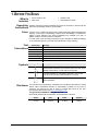
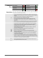
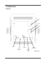
User Manual TABLE OF CONTENTS 1. Before You Begin ...........................................................................................................3 What Is Included ......................................................................................................................... 3 Unpacking Instructions ................................................................................................................ 3 Claims ................................................................................................................................................. 3 Text Conventions ........................................................................................................................ 3 Symbols ...................................................................................................................................... 3 Disclaimer ................................................................................................................................... 3 Product at a Glance..................................................................................................................... 4 Safety Notes ............................................................................................................................... 4 2. Introduction ....................................................................................................................5 Overview ..................................................................................................................................... 5 Dimensions ................................................................................................................................. 6 3. Setup ...............................................................................................................................7 AC Power .................................................................................................................................... 7 Fuse Replacement ............................................................................................................................... 7 Power Linking ...................................................................................................................................... 8 Mounting ..................................................................................................................................... 9 Orientation ........................................................................................................................................... 9 Rigging ................................................................................................................................................ 9 4. Operation ......................................................................................................................10 Configuration (DMX).................................................................................................................. 10 Starting Address ................................................................................................................................ 10 DIP Switch Reference Guide .............................................................................................................. 11 DMX Channel Modes, Assignments, and Values ....................................................................... 12 2-Channel .......................................................................................................................................... 12 Configuration (Standalone) ........................................................................................................ 12 Sound-Active Mode ............................................................................................................................ 12 Strobe Mode ...................................................................................................................................... 12 Full On Mode ..................................................................................................................................... 12 Master/Slave Mode ............................................................................................................................ 13 5. Technical Information ..................................................................................................14 Product Maintenance ................................................................................................................ 14 6. Technical Specifications ..............................................................................................15 Returns ..................................................................................................................................... 16 Contact Us ................................................................................................................................ 16 Page 2 of 16 Techno Strobe™ 168 User Manual (Rev. 2) 1. BEFORE YOU BEGIN What Is Included • • Techno Strobe™ 168 Power Cord • • Warranty Card Quick Reference Guide Unpacking Instructions Carefully unpack the product immediately and check the container to make sure all the parts are in the package and are in good condition. Claims If the box or the contents (the product and included accessories) appear damaged from shipping, or show signs of mishandling, notify the carrier immediately, not CHAUVET®. Failure to report damage to the carrier immediately may invalidate your claim. In addition, keep the box and contents for inspection. For other issues, such as missing components or parts, damage not related to shipping, or concealed damage, file a claim with CHAUVET® within 7 days of delivery. Text Conventions Symbols Convention [10] 1~512 50/60 Settings Menu > Settings <ENTER> ON Symbol Meaning A DIP switch to be configured A range of values A set of values of which only one can be chosen A menu option not to be modified A sequence of menu options to be followed A key to be pressed on the product’s control panel A value to be entered or selected Meaning Critical installation, configuration, or operation information. Not following these instructions may make the product not work, cause damage to the product, or cause harm to the operator. Important installation or configuration information. The product may not function correctly if this information is not used. Useful information. Disclaimer The information and specifications contained in this User Manual are subject to change without notice. CHAUVET® assumes no responsibility or liability for any errors or omissions, and reserves the right to revise or recreate this manual at any time. Download the latest version from www.chauvetlighting.com. © Copyright 2013 CHAUVET®. All rights reserved. Electronically published by CHAUVET® in the United States of America. Author Date Editor Updated A. Leon 10/25/12 S. Diaz 1/28/13 Techno Strobe™ 168 User Manual (Rev. 2) Page 3 of 16 Product at a Glance Use on Dimmer Outdoor Use Sound-Active DMX Master/Slave Safety Notes Auto Programs Auto-ranging Power Supply Replaceable Fuse User-Serviceable Duty Cycle These notes include important information about the mounting, usage, and maintenance of this product; read before using the product. • • • • • • • • • • • • • • • • • • • • Page 4 of 16 Always connect the product to a grounded circuit to avoid the risk of electrocution. Always disconnect the product from the power source before cleaning or replacing the fuse. Avoid direct eye exposure to the light source while the product is on. Make sure the power cord is not crimped or damaged. Never disconnect the product from power by pulling or tugging on the cord. If mounting the product overhead, always secure to a fastening device using a safety cable. Make sure there are no flammable materials close to the product when operating. Do not touch the product’s housing when operating because it may be very hot. Always make sure that the voltage of the outlet to which you are connecting the product is within the range stated on the decal or rear panel of the product. The product is for indoor use only! (IP20) To prevent risk of fire or shock, do not expose the product to rain or moisture. Always install the product in a location with adequate ventilation, at least 20 in (50 cm) from adjacent surfaces. Be sure that no ventilation slots on the product’s housing are blocked. Never connect the product to a dimmer. Make sure to replace the fuse with another of the same type and rating. Never carry the product from the power cord or any moving part. Always use the hanging/mounting bracket. The maximum ambient temperature (Ta) is 104° F (40° C). Do not operate the product at higher temperatures. In the event of a serious operating problem, stop using the product immediately. Never try to repair the product. Repairs carried out by unskilled people can lead to damage or malfunction. Contact the nearest authorized technical assistance center. This product is not intended for permanent installation. Keep this User Manual for future use. If you sell the product to another user, be sure to give this document to the next owner. Techno Strobe™ 168 User Manual (Rev. 2) 2. INTRODUCTION Overview Power Out Power In Fuse Holder DMX In DMX Out DIP Switches Techno Strobe™ 168 User Manual (Rev. 2) Intensity Adjustment Knob Speed Adjustment Knob Back Panel View Page 5 of 16 Dimensions Page 6 of 16 Techno Strobe™ 168 User Manual (Rev. 2) 3. SETUP AC Power The Techno Strobe™ 168 has an auto-ranging power supply and it can work with an input voltage range of 100~240 VAC, 50/60 Hz. To determine the product’s power requirements (circuit breaker, power outlet, and wiring), use the current value listed on the label affixed to the product’s back panel, or refer to the product’s specifications chart. The listed current rating indicates the product’s average current draw under normal conditions. Always connect the product to a protected circuit (circuit breaker or fuse). Make sure the product has an appropriate electrical ground to avoid the risk of electrocution or fire. Never connect the product to a rheostat (variable resistor) or dimmer circuit, even if the rheostat or dimmer channel serves only as a 0~100% switch. Fuse Replacement Disconnect the product from power before replacing the fuse. 1. 2. 3. 4. 5. 6. Disconnect the product from power. Wedge the tip of a flat-head screwdriver into the slot of the fuse holder. Pry the fuse holder out of the housing. Remove the blown fuse from the holder. Replace with a fuse of the exact same type and rating. Insert the fuse holder back in place and reconnect power. Installed fuse (held by plastic clip) Safety cap Spare fuse holder (inside safety cap) A spare fuse is not included; however, the safety cap has room for a spare. Always replace a blown fuse with another of the same type and rating. Techno Strobe™ 168 User Manual (Rev. 2) Page 7 of 16 Power Linking The product provides power linking via the Edison/IEC outlet located in the back of the unit. st Power Linking Diagram 1 Product 2nd Product 3rd Product Additional Products You can power link up to 34 Techno Strobe™ 168 units on 120 VAC or up to 57 Techno Strobe™ 168 units on 230 VAC. The power linking diagram shown above corresponds to the North American version of the product ONLY! If using the product in other markets, you must consult with the local CHAUVET® distributor as power linking connectors and requirements may differ in your country or region. Page 8 of 16 Techno Strobe™ 168 User Manual (Rev. 2) Mounting Before mounting the product, read and follow the safety recommendations indicated in the Safety Notes. Orientation The Techno Strobe™ 168 may be mounted in any position; however, make sure adequate ventilation is provided around the product. Rigging • Before deciding on a location, always make sure there is easy access to the product for maintenance and programming. • Make sure that the structure or surface onto which you are mounting the product can support the product’s weight (see the Technical Specifications). • When mounting the product overhead, always use a safety cable. Mount the product securely to a rigging point, such as an elevated platform or a truss. • When rigging the product onto a truss, you should use a mounting clamp of appropriate weight capacity. The bracket has 13-mm holes, which are appropriate for this purpose. • When power linking multiple products, you must always consider the length of the power linking cable and mount the products close enough for the cable to reach. • The bracket adjustment knobs allow for directional adjustment when aiming the product to the desired angle. Only loosen or tighten the bracket knobs manually. Using tools could damage the knobs. • The mounting bracket also serves as floor supports/allow for surface mounting. When mounting the product on the floor, make sure that the product and cables are away from people and vehicles. Mounting Clamp Safety Cable Mounting Bracket Mounting Diagram Bracket Adjustment Knob Techno Strobe™ 168 User Manual (Rev. 2) Page 9 of 16 4. OPERATION Configuration (DMX) Starting Address Set the product in DMX mode to control with a DMX controller. 1. Connect the product to a suitable power outlet. 2. Connect a DMX cable from the DMX output of the DMX controller to the DMX input socket on the product. When selecting a starting DMX address, always consider the number of DMX channels the selected DMX mode uses. If you choose a starting address that is too high, you could restrict the access to some of the product’s channels. The Techno Strobe™ 168 uses up to 2 DMX channels in its 2-channel personality DMX mode, which defines the highest configurable address to 511. The DMX starting address is configured through the DIP switches located on the back panel. If unfamiliar with DMX or DIP switches, download the DMX Primer from www.chauvetlighting.com. Starting Address Settings DIP Switch 1 2 3 4 5 6 7 8 9 Value 1 2 4 8 16 32 64 128 256 Select the desired starting address by setting DIP switches [1]~[9] to On or Off until the sum of the value of the DIP switches in the On position matches the desired address number. Refer to the examples below for more information. Starting Address 1. To select DMX address 1, set DIP switch [1] to On. Examples 2. To select DMX address 64, set DIP switch [7] to On. 3. Page 10 of 16 To select DMX address 31, set DIP switches [1], [2], [3], [4], and [5] to On. (1 + 2 + 4 + 8 + 16 = 31) Techno Strobe™ 168 User Manual (Rev. 2) DIP Switch Reference Guide You can use the table below to set your fixture’s DIP switches. Imagine that you want to find the DIP switch settings for DMX address 328: 1. Find 328 among the addresses from the table and point at it with your finger. 2. Move your finger to the left and you will find the settings for DIP switches [1]~[5]. DIP switches [1], [2], [3], and [5] are Off (0), while DIP switch [4] is On (1). 3. Go back and point at the 328 address. 4. Move your finger upward and you will find the settings for DIP switches [6]~[9]. DIP switches [6] and [8] are Off (0), while DIP switches [7] and [9] are On (1). 5. See below how the DIP switches will look after configuring them. #9 #8 #7 #6 #1 #2 #3 #4 #5 DIP Switches 0 = Off 1 = On 0 1 0 1 0 1 0 1 0 1 0 1 0 1 0 1 0 1 0 1 0 1 0 1 0 1 0 1 0 1 0 1 0 0 1 1 0 0 1 1 0 0 1 1 0 0 1 1 0 0 1 1 0 0 1 1 0 0 1 1 0 0 1 1 0 0 0 0 1 1 1 1 0 0 0 0 1 1 1 1 0 0 0 0 1 1 1 1 0 0 0 0 1 1 1 1 0 0 0 0 0 0 0 0 1 1 1 1 1 1 1 1 0 0 0 0 0 0 0 0 1 1 1 1 1 1 1 1 0 0 0 0 0 0 0 0 0 0 0 0 0 0 0 0 1 1 1 1 1 1 1 1 1 1 1 1 1 1 1 1 Techno Strobe™ 168 User Manual (Rev. 2) 0 0 0 0 0 0 0 0 1 1 1 1 1 1 1 1 0 0 0 0 1 1 1 1 0 0 0 0 1 1 1 1 0 0 1 1 0 0 1 1 0 0 1 1 0 0 1 1 0 1 0 1 0 1 0 1 0 1 0 1 0 1 0 1 320 321 322 323 324 325 326 327 328 329 330 331 332 333 334 335 336 337 338 339 340 341 342 343 344 345 346 347 348 349 350 351 352 353 354 355 356 357 358 359 360 361 362 363 364 365 366 367 368 369 370 371 372 373 374 375 376 377 378 379 380 381 382 383 384 385 386 387 388 389 390 391 392 393 394 395 396 397 398 399 400 401 402 403 404 405 406 407 408 409 410 411 412 413 414 415 416 417 418 419 420 421 422 423 424 425 426 427 428 429 430 431 432 433 434 435 436 437 438 439 440 441 442 443 444 445 446 447 448 449 450 451 452 453 454 455 456 457 458 459 460 461 462 463 464 465 466 467 468 469 470 471 472 473 474 475 476 477 478 479 480 481 482 483 484 485 486 487 488 489 490 491 492 493 494 495 496 497 498 499 500 501 502 503 504 505 506 507 508 509 510 511 DMX Address ----1 2 3 4 5 6 7 8 9 10 11 12 13 14 15 16 17 18 19 20 21 22 23 24 25 26 27 28 29 30 31 32 33 34 35 36 37 38 39 40 41 42 43 44 45 46 47 48 49 50 51 52 53 54 55 56 57 58 59 60 61 62 63 64 65 66 67 68 69 70 71 72 73 74 75 76 77 78 79 80 81 82 83 84 85 86 87 88 89 90 91 92 93 94 95 96 97 98 99 100 101 102 103 104 105 106 107 108 109 110 111 112 113 114 115 116 117 118 119 120 121 122 123 124 125 126 127 128 129 130 131 132 133 134 135 136 137 138 139 140 141 142 143 144 145 146 147 148 149 150 151 152 153 154 155 156 157 158 159 160 161 162 163 164 165 166 167 168 169 170 171 172 173 174 175 176 177 178 179 180 181 182 183 184 185 186 187 188 189 190 191 192 193 194 195 196 197 198 199 200 201 202 203 204 205 206 207 208 209 210 211 212 213 214 215 216 217 218 219 220 221 222 223 224 225 226 227 228 229 230 231 232 233 234 235 236 237 238 239 240 241 242 243 244 245 246 247 248 249 250 251 252 253 254 255 256 257 258 259 260 261 262 263 264 265 266 267 268 269 270 271 272 273 274 275 276 277 278 279 280 281 282 283 284 285 286 287 288 289 290 291 292 293 294 295 296 297 298 299 300 301 302 303 304 305 306 307 308 309 310 311 312 313 314 315 316 317 318 319 Page 11 of 16 DMX Channel Modes, Assignments, and Values 2-Channel Configuration (Standalone) Channel Function 1 Control Functions 2 Dimmer Value 000 006 241 251 000 005 240 250 255 255 Percent/Setting No function Strobe speed, slow to fast Full On (all LEDs on) Sound-Active mode 0~100% Set the product in one of the standalone modes to control without a DMX controller. The standalone modes are accessed through the DIP switches located on the back panel. 1. Connect the product to a suitable power outlet. Never connect a product that is operating in any standalone mode (either Static, Automatic, or Sound) to a DMX string connected to a DMX controller. Products in standalone mode may transmit DMX signals that could interfere with the DMX signals from the controller. Sound-Active Mode To enable the Sound-Active mode, do the following: 1. Set all DIP switches to Off. 2. Turn the Speed Adjustment knob counterclockwise to the minimum position. 3. Turn the Intensity Adjustment knob until the product starts responding to the beat of the music. The product will only respond to low frequencies of music (bass and drums). Strobe Mode To enable the Strobe mode, do the following: 1. Set all DIP switches to Off. 2. Turn the Speed Adjustment knob between the minimum and maximum positions to the desired strobe speed. All-On Mode To enable the All-On mode, do the following: 1. Set all DIP switches to Off. 2. Turn the Speed Adjustment knob clockwise to the maximum position. Due to its innovate design, this unit can be run strobing all night, but continuous All-On operation should not be used for more than 30 minutes at 120V or 15 minutes at 230V. Page 12 of 16 Techno Strobe™ 168 User Manual (Rev. 2) Master/Slave Mode The Master/Slave mode allows a single Techno Strobe™ 168 unit (the “master”) to control the actions of one or more Techno Strobe™ 168 units (the “slaves”) without the need of a DMX controller. The master unit will be set to operate in Manual or SoundActive mode, while the slave units will be set to the same DMX starting address. Once set and connected, the slave units will operate in unison with the master unit. Configure the units as indicated below. Slave units: 1. Set the DMX address to 1. 2. Connect the DMX input of the subsequent slave units to the DMX output of the previous slave unit. 3. Finish setting and connecting all the slave units. 4. Connect the DMX input of the first slave unit to the DMX output of the master unit. Master unit: 1. Set the master unit to operate in Manual or Sound-Active mode. 2. Make the master unit the first unit in the DMX daisy chain. • Configure all the slave units before connecting the master unit to the DMX daisy chain. • Never connect a DMX controller to a DMX string configured for Master/Slave operation because the controller may interfere with the signals from the master unit. • Do not connect more than 31 slave units to the master unit. Techno Strobe™ 168 User Manual (Rev. 2) Page 13 of 16 5. TECHNICAL INFORMATION Product Maintenance Dust build-up reduces light output performance and can cause overheating. This can lead to reduction of the light source’s life. To maintain optimum performance and minimize wear, clean the product at least twice a month. However, usage and environmental conditions contribute to increased cleaning frequency. To clean the product, follow the instructions below: • Unplug the product from power. • Wait until the product is at room temperature. • Use a vacuum (or dry compressed air) and a soft brush to remove dust collected on the external surface/vents. • Clean all glass/transparent surfaces with a mild soap solution, ammonia-free glass cleaner, or isopropyl alcohol. • Apply the solution directly to a soft, lint-free cotton cloth or a lens cleaning tissue. • Softly wipe any dirt or grime to the outside edges of the glass/transparent surface. • Gently polish the glass/transparent surfaces until they are free of haze and lint. Always dry the glass/transparent surfaces carefully after cleaning them. Page 14 of 16 Techno Strobe™ 168 User Manual (Rev. 2) 6. TECHNICAL SPECIFICATIONS Dimensions and Weight Length Width Height Weight 5.5 in (140 mm) 9.4 in (238 mm) 8.7 in (220 mm) 2.3 lbs (1.0 kg) Note: Dimensions in inches rounded to the nearest decimal digit. Power Power Supply Type Range Voltage Selection Switching (internal) 100~240 V, 50/60 Hz Auto-ranging Parameter 120 V, 60 Hz 230 V, 50 Hz 32 W Consumption 28 W Operating current 0.2 A 0.1 A Power linking current (units) 8 A (34 units) 8 A (57 units) Fuse/Breaker T 1 A, 250 V T 1 A, 250 V Power I/O U.S./Worldwide UK/Europe Power input connector IEC IEC Power output connector Edison IEC Power Cord plug Edison (U.S.) Local plug Light Source Type LED Photo Optic Thermal DMX Ordering Color Quantity White 168 Parameter Illuminance @ 2 m 500 lx Beam angle 24º Field angle 44 Strobe Rate 0~12 Hz Maximum External Temp. Cooling System 104° F (40° C) Convection I/O Connectors Connector Type Channel Range 3-pin XLR Sockets 2 Product Name Item Code UPC Number Techno Strobe™ 168 16050595 781462209438 Techno Strobe™ 168 User Manual (Rev. 2) Page 15 of 16 To return a product or request support: • • • In the U.S., contact CHAUVET® World Headquarters (see below). In the UK or Ireland, contact CHAUVET® Europe Ltd. (see below). In any other country, DO NOT contact CHAUVET®. Contact your distributor. See www.chauvetlighting.com for distributors outside the U.S., United Kingdom, or Ireland. If you live outside the U.S., United Kingdom, or Ireland, contact your distributor of record and follow their instructions on how to return CHAUVET® products to them. Visit our website for contact details. Returns Call the corresponding CHAUVET® Technical Support office and request a Return Merchandise Authorization (RMA) number before shipping the product. Be prepared to provide the model number, serial number, and a brief description of the cause for the return. You must send the merchandise prepaid, in its original box, and with its original packing and accessories. CHAUVET® will not issue call tags. Clearly label the package with the RMA number. CHAUVET® will refuse any product returned without an RMA number. Write the RMA number on a properly affixed label. DO NOT write the RMA number directly on the box. Before sending the product, clearly write the following information on a piece of paper and place it inside the box: • Your name • Your address • Your phone number • The RMA number • A brief description of the problem Be sure to pack the product properly. Any shipping damage resulting from inadequate packaging will be your responsibility. FedEx packing or double-boxing are recommended. CHAUVET® reserves the right to use its own discretion to repair or replace returned product(s). Contact Us World Headquarters CHAUVET® General Information Address: 5200 NW 108th Avenue Sunrise, FL 33351 Voice: (954) 577-4455 Fax: (954) 929-5560 Toll free: (800) 762-1084 Technical Support Voice: (954) 577-4455 (Press 4) Fax: (954) 756-8015 Email: [email protected] World Wide Web www.chauvetlighting.com Page 16 of 16 United Kingdom & Ireland CHAUVET® Europe Ltd. General Information Address: Unit 1C Brookhill Road Industrial Estate Pinxton, Nottingham, UK NG16 6NT Voice: +44 (0)1773 511115 Fax: +44 (0)1773 511110 Technical Support Email: [email protected] World Wide Web www.chauvetlighting.co.uk Techno Strobe™ 168 User Manual (Rev. 2)