1
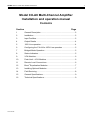
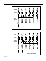
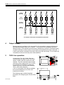
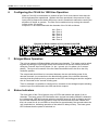
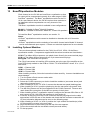
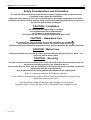
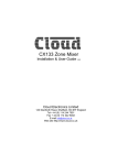
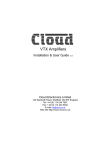
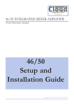
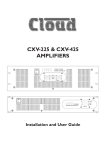
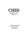
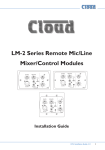
CX-A6 Amplifier Installation & User Guide V8.0 Cloud Electronics Limited 140 Staniforth Road, Sheffield, S9 3HF England Tel + 44 (0) 114 244 7051 Fax + 44 (0) 114 242 5462 E-mail [email protected] Web site http://www.cloud.co.uk 1 CX-A6 INSTALLATION AND OPERATION MANUAL Model CX-A6 Multi-Channel Amplifier Installation and operation manual Contents Section 15-07-02 V8 Page 1 General Description ...................................................................2 2 Installation ..................................................................................2 3 Input Facilities ............................................................................2 4 Output Details ............................................................................4 5 100V Line operation ...................................................................4 6 Configuring the CX-A4 for 100V Line operation .........................5 7 Bridged Mode Operation ............................................................5 8 Status Indicators ........................................................................5 9 VCA Modules .............................................................................6 10 Peak Limit + VCA Modules ........................................................6 11 Remote Level Connections ........................................................6 12 Bose Equalisation Modules ......................................................7 13 Installing Optional Modules ........................................................7 14 Field Servicing............................................................................8 15 General Specifications ...............................................................9 16 Technical Specifications .............................................................9 CX-A6 INSTALLATION AND OPERATION MANUAL 1 2 Safety Notes • Do not expose the unit to water or moisture • Do not expose the unit to naked flames. • Do not block or restrict any air vent • Do not operate the unit in ambient temperatures above 35oC • Do not touch any part or terminal carrying the hazardous live symbol ( ) while power is supplied to the unit. • Do not perform any internal adjustments unless you are qualified to do so and fully understand the hazards associated with mains operated equipment. • The unit has no user serviceable parts. Refer any servicing to qualified service personnel. • If the moulded plug is cut off the lead for any reason, the discarded plug is a potential hazard and should be disposed of in a responsible manner. For more detailed information refer to the rear of the manual. 2 General The CX-A6 is a six-channel power amplifier with a maximum output of 120 watts into loads of 4 ohms per channel. The unit features extremely low distortion and low noise together with a high slew rate. Full circuit protection is provided and the load is disconnected if the heat sink overheats or any DC is detected at the output. A five-second switch-on delay operates to avoid any switching thumps or other extraneous signals reaching the speaker system. All six input amplifiers are balanced and connect via 3 pin XLR type connectors with adjacent level controls, all mounted on the rear panel. Input signal routing switches are provided and allow the unit to operate in many configurations whilst retaining simple input connections. The CX-A6 amplifier can be used with up to three optional plug-in two channel VCA modules to provide remote level control. Each plug-in module can operate as two individual attenuators or can be linked to operate as a stereo pair with one remote level control. 3 Installation The CX-A6 is suitable for mounting in a standard 19" equipment rack and occupies two units of rack space. Sufficient ventilation must be provided for the unit. The amplifier draws cool air through the front panel and exhausts through the right side and care must be taken not to obstruct the airflow otherwise the unit may intermittently turn off due to the built-in thermal protection. Applications that require long, sustained operation at high power levels should allow a 1U space above and below the unit. The unit is 325mm deep but a depth of 400mm should be allowed to clear the connectors. 3 Input Facilities All six inputs are balanced and use 3 pin XLR type connectors. All inputs are wired to the standard convention of pin 1 ground, pin 2 in-phase, pin 3 reverse phase, with the shell of the connector connected to the chassis. If the unit is operating in a location which has a high level of electrical or magnetic disturbance or is close to a TV or radio transmitter, we suggest that the input cable screen be connected to the shell of a metal XLR type connector. If the signal is from an unbalanced source, connect pin 3 to pin 1 (ground) inside the XLR type connector and use pin 2 as hot. Each input has a level control adjacent to the respective XLR type connector. Input switching is provided on input channels 2 to 5 allowing a wide variety of input routing configurations. See the schematic diagrams showing details of various routing possibilities.With all input switches depressed, the unit operates as six independent amplifiers. Three stereo pairs, driven from one stereo source and six channels driven from one mono source are also possible together with a combination of the two by suitably configuring the input routing switches. 15-07-02 V8 3 CX-A6 INSTALLATION AND OPERATION MANUAL POWER AMPLIFIER 1 2 3 4 5 6 LEVEL CONTROL SOURCE SWITCHES INPUT AMPLFIER 1 2 1 1 3 2 2 4 3 1 5 4 2 6 5 6 INPUT 1 FROM MONO SOURCE POWER AMPLIFIER 1 SIX CHANNELS DRIVEN FROM ONE MONO SOURCE 2 3 4 5 6 LEVEL CONTROL SOURCE SWITCHES INPUT AMPLFIER 1 2 1 2 INPUT 1 INPUT 2 FROM STEREO SOURCE 15-07-02 V8 1 3 3 2 4 4 1 5 5 THREE STEREO PAIRS DRIVEN FROM ONE STEREO SOURCE 2 6 6 4 CX-A6 INSTALLATION AND OPERATION MANUAL POWER AMPLIFIER 1 2 3 4 5 6 LEVEL CONTROL SOURCE SWITCHES 1 INPUT AMPLFIER 2 1 3 2 4 1 5 2 6 1 2 3 4 5 6 INPUT 1 INPUT 2 INPUT 3 INPUT 4 INPUT 5 INPUT 6 SIX CHANNELS OPERATING AS INDEPENDENT AMPLIFIERS 4 Output Details Binding posts are provided on the rear panel for the six speaker outputs and these can accommodate flexible leads up to 2.50mm². The posts are not compatible with 4mm 'Banana' plugs. Each speaker lead should be a twisted pair; having an untwisted section of cable for as little as 10cm before its termination will significantly increase cross-talk. It is also good practice to distance the output wiring from the input wiring. Do not make any connections to the unit with the power cable attached. 5 100V Line operation Connecting a CXL-100 100W 100V-line module across an output of the CX-A6 will obtain a 100W 100V-line output from that channel. The CXL-100 has to be mounted externally of the amplifier and 70V or 100Vline operation is selectable by taking the output of the CXL-100 from the necessary 70V or 100V screw terminal. A 2U 19" rack panel (CXL-600) is available that accommodates up to six CXL-100 transformer modules. The following page contains important information on configuring the CX-A6s 65Hz filters 15-07-02 V8 5 CX-A6 INSTALLATION AND OPERATION MANUAL 6 Configuring the CX-A6 for 100V-line Operation When a CXL-100 is connected to a channel of the CX-A6, that channel must have its 65Hz high-pass filter operational. Without this filter operational, the presence of high input levels at frequencies below 50Hz may result in transformer saturation causing the amplifiers VI limiter to operate. The filter can be switched on by moving the relevant jumper to the ‘IN’ position. Jumpers J1-6 are associated with the channels of the CX-A6 as follows: J1 = Zone 1 J2 = Zone 2 J3 = Zone 3 J4 = Zone 4 J5 = Zone 5 J6 = Zone 6 Diagram to Show Location of J1-6 on the CX-A6 PCB 7 Bridged Mono Operation The unit can operate in Bridged Mode using any two channels. The inputs must be wired together by linking the input signal at the XLR connectors of the two relevant channels, wiring the "second" input out of phase (i.e. pin 1 ground, pin 3 in-phase, pin 2 reverse phase). The input level controls of the two channels should both to be set to the fully clockwise position. The output load should then be connected between the two red binding posts of the relevant channels (no connection to the black binding posts of the relevant channels), ensuring that the positive wire is connected to the "first" red binding post and the negative wire is connected to the "second" binding post. Thus for example it is possible to configure four channels as two bridged outputs allowing a stereo input to be delivered to two 240 watt 8 ohm outputs. 8 Status Indicators The front panel of the CX-A6 has an array of LED’s that indicate the status of all six channels. The lower green LED illuminates when a signal exceeding 500mW is detected, the yellow 'peak' LED will illuminate when the amplifier output is close to clipping and the top red LED indicates that the protection relay has disconnected the load. Please note that it is normal for all six red LED's to illuminate for approximately five seconds when the unit is switched on, indicating operation of the switch-on delay circuitry. The lower green LED indicates that the power is switched on. 15-07-02 V8 6 CX-A6 INSTALLATION AND OPERATION MANUAL 9 VCA Modules A two-channel VCA module is available as a plug-in option for the CX-A6 (see section 13 for installation details) and can be used with either one or two control plates. The unit can operate two channels independently or switched to provide stereo attenuation via one control plate. For independent operation, the switch should be in the 'solo' position (in), with the remote level controls connected to both 3 pin connectors. For stereo operation, position the switch in the link position (out) and connect the level control to the left connector only. The RL-1 remote control plate is compatible with domestic electrical accessories and can be mounted onto a standard British flush or surface mounted 25mm deep back box. Two-core cable with overall screen should be used to connect the remote level control to the module mounted inside the CX-A6. The circuitry uses the industry standard 'Thats 2150A' VCA providing very low distortion and up to 90dB attenuation. The VCA module can be wired to provide muting by using an auxiliary relay connected to a fire alarm control panel. Note: A VCA module cannot be installed to channels that already have a Bose equalisation module installed. 10 Peak Limit + VCA Modules A two channel peak limit + VCA module is available (see section 13 for installation details) which performs the same functions as the module described above with the added benefit of a peak limiter which is factory set to prevent clipping. A 'Peak Limit' on/off switch is mounted on the rear panel that can be over-ridden by configuring a PCB mounted circuit jumper. The limiter operates with hard knee characteristics and has an infinite compression ratio. Note: A Peak Limit + VCA module cannot be installed to channels that already have a Bose equalisation module installed. 11 Remote Level Plate Connections CLIP PROTECT LINK 1 ON REMOTE LEVEL 1+2 OFF 1 2 3 1 SOLO 1 3 2 2 2 SOURCE 1 2 REAR VIEW OF CX-A6 AMPLIFIER USE 2 CORE SCREENED CABLE CONNECT SCREEN TO TERMINAL 1 1 2 3 REAR VIEW OF LEVEL CONTROL PLATE 15-07-02 V8 CX-A6 INSTALLATION AND OPERATION MANUAL 12 7 Bose Equalisation Modules Each channel on the CX-A6 can have Bose equalisation so that its output will be compensated correctly for a wide range of 100Vline Bose speakers. The Bose equalisation module for the CXA6 is a two-channel device; the CX-A6 requires three modules to be installed to allow compensation on every channel of the amplifier. The Bose equalisation module is available in two configurations: Model 8 – Suitable for Bose Model 8 Speakers Model 32 – Suitable for the Bose Model 25, 32 and 102 speakers To install the Bose equalisation module, see section 13. Notes: • A Bose equalisation module cannot be installed to channels with a VCA module installed. • A Bose equalisation module consisting of a model 8 channel and a Model 32 channel can be manufactured upon request. Contact our technical department for more details. 13 Installing Optional Modules There are three optional modules for the CX-A6, the VCA-2, VCAL-1 & the Bose equalisation module. Components supplied with the various modules are listed below: VCA-2: Two 40mm M3 hex spacers, one plastic insert & two 3-pin screw terminal plugs. VCAL-1: Two 40mm M3 hex spacers & two 3-pin screw terminal plugs. Bose EQ: Two 25mm M3 hex spacers. The CX-A6 connectors to install the VCA modules are to the rear of the amplifier on the input PCB clearly marked on the PCB as ‘CON X TO VCA MODULE’ where ‘X’ is 1,2 or 3 see below: CON 1 = Channel 1&2 CON 2 = Channel 3&4 CON 3 = Channel 5&6 When installing modules, follow the instructions below carefully. Incorrect installation can cause damage. 1. Turn the power off and remove mains cable. 2. Remove the top panel. 3. Select the CX-A6 connector you wish to install the module to (see notes above) and remove the jumpers from it. 4. When installing a VCAL-1 or VCA-2, remove the relevant rear panel blanking plate. 5. When installing a VCA-2, push the plastic plug into the rear panel ‘clip protect’ hole. 6. Two M3 fixing screws can be found adjacent to the CX-A6 connector. Remove and retain these two screws then fix the M3 hex spacers in their place. 7. When installing a Bose equalisation module, configure the relevant 65Hz filter to ‘IN’ and connect a CXL-100 100V line transformer (see section 6) 8. Push the 10-way plug onto the CX-A6 connector with the plug aligned so the cable approaches it from the rear of the chassis and check that the connector mates with all 10 pins (orientation diagrams can be seen on the following page). 9. When installing a VCAL-1 or VCA-2, position the 3-pin sockets and switch(es) of the VCA through the cut-outs in the rear panel. 10. Align the two holes in the module over the top of the two spacers. 11. Secure the module with the two M3x6 screws (removed earlier). 12. Fit the top panel. 15-07-02 V8 8 CX-A6 INSTALLATION AND OPERATION MANUAL Top Down View of Bose Equalisation Module Orientation Bose Equalisation Module Orientation (Side View) 14 VCA Module Orientation (Side View) Field Servicing The CX-A6 is ruggedly built and uses proven reliable circuitry. It requires no more than the occasional removal of any dust that may have built up inside the unit as a result of the forced cooling. In the unlikely event of failure, the power amplifier module (2 channels) can be replaced without special tools and is available as a tested replacement complete with heat sink. Proceed as follows to replace the power module: Disconnect all the leads and connectors from the rear of the unit. Ensure that the mains supply lead has been disconnected. Remove the CX-A6 from the equipment rack. Remove the top panel. The power amplifier modules are arranged as three dual channel units. Locate the faulty unit and remove both the 7 way power cable & the 10 way ribbon connector. Remove the four fixing screws from the bottom of the unit to release the module. Now fit the replacement unit by proceeding in reverse order. No setting up is required and the unit should operate normally. 15-07-02 V8 9 CX-A6 INSTALLATION AND OPERATION MANUAL 15 General Specifications Inputs Outputs Protection Status Indicators Cooling Dimensions Weight 16 Balanced via 3 pin XLR type connector. Binding Posts for flexible cables up to 2.5mm² VI limiting, DC offset, Thermal and Switch-on Delay LED indicators on each channel for Signal, Peak & Protect Force cooled using a two speed DC fan. 482.6mm x 88.0mm (2U) x 325.0mm deep (+ connectors) 10kg net Technical Specifications Rated output Bridged Output Frequency Response THD VCA Module THD Input Sensitivity Input Impedance Noise Slew Rate Power Input Fuse rating 120 watts/4 ohm load 85 watts/8 ohm load 240 watts/8 ohm load ±1dB 10Hz to 50kHz <0.005% 1kHz <0.05% 20Hz/20kHz 8 1dB below rated output <0.03% 20Hz/20kHz 0dBu (775mV) 10k balanced / 5k unbalanced >90dB below rated output 35V/µS (power amplifier) 230V ±5% (115V ±5% available) 230V - T5A H 115V - T10A H This product conforms to the following European EMC Standards: BS EN 55103-1:1997 BS EN 55103-2:1997 This product has been tested for use in commercial and light industrial environments. If the equipment is used in controlled EMC environments, the urban outdoors, heavy industrial environments or close to railways, transmitters, overhead power lines etc. the performance of the unit may be degraded. The product conforms to the following European electrical safety standard. BS EN 60065:1998 15-07-02 V8 CX-A6 INSTALLATION AND OPERATION MANUAL 10 Safety Considerations and Information The unit must be earthed. Ensure that the mains power supply provides an effective earth connection using a three wire termination. When the mains switch is in the off ‘O’ position the live and neutral conductors of the mains transformer are disconnected, however some parts of the product will still remain connected to the live and neutral mains conductors CAUTION – Installation Do not expose the unit to water or moisture Do not expose the unit to naked flames. Do not block or restrict any air vent Do not operate the unit in ambient temperatures above 35oC CAUTION – Hazardous Live Do not touch any part or terminal carrying the hazardous live symbol ( ) while power is supplied to the unit as it can result in electric shock. Terminals to which the hazardous live symbol refers require installation by qualified personnel CAUTION - Mains Fuse Replace the mains fuse only with the same type and rating as marked on the rear panel. The fuse body size is 20mm x 5mm. CAUTION – Servicing The unit contains no user serviceable parts. Refer servicing to qualified service personnel. Do not perform servicing unless you are qualified to do so. Disconnect the power cable from the unit before removing the top and do not make any internal adjustments with the unit switched on. Only reassemble the unit using bolts/screws identical to the original parts Bose is a registered trademark of The Bose Corporation In the interest of continuing improvements cloud electronics limited reserves the right to alter specifications without prior notice. Cloud Electronics Limited 140 Staniforth Road Sheffield S9 3HF England Telephone +44(0) 114 244 7051 Fax +44(0) 114 242 5462 E-mail: [email protected] 15-07-02 V8