1
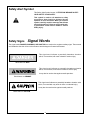
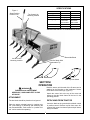
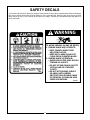
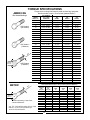
BUSH HOG
®
RBX 720 & 840
RETRACTABLE SHANK BOX BLADES
OPERATOR’S MANUAL
ASSEMBLY ● OPERATION ● MAINTENANCE
502
$4.00
50037881
CONGRATULATIONS!
You have invested in the best implement of its type on the market today.
The care you give your Bush Hog implement will greatly determine your satisfaction
with its performance and its service life. We urge a careful study of this manual to provide
you with a thorough understanding of your new implement before operating, as well as
suggestions for operation and maintenance.
If your manual should become lost or destroyed, Bush Hog will be glad to provide you with
a new copy. Order from Bush Hog, P. O. Box 1039, Selma, Alabama 36702-1039.
As an authorized Bush Hog dealer, we stock genuine Bush Hog parts which are
manufactured with the same precision and skill as our original equipment. Our trained
service personnel are well informed on methods required to service Bush Hog equipment,
and are ready and able to help you.
Should you require additional information or assistance, please contact us.
YOUR AUTHORIZED
BUSH HOG DEALER
BECAUSE BUSH HOG MAINTAINS AN ONGOING
PROGRAM OF PRODUCT IMPROVEMENT, WE
RESERVE THE RIGHT TO MAKE IMPROVEMENTS IN
DESIGN OR CHANGES IN SPECIFICATIONS WITHOUT INCURRING ANY OBLIGATION TO INSTALL
THEM ON UNITS PREVIOUSLY SOLD.
BECAUSE OF THE POSSIBILITY THAT SOME
PHOTOGRAPHS IN THIS MANUAL WERE TAKEN OF
PROTOTYPE MODELS, PRODUCTION MODELS MAY
VARY IN SOME DETAIL. IN ADDITION, SOME
PHOTOGRAPHS MAY SHOW SHIELDS REMOVED
FOR PURPOSES OF CLARITY. NEVER OPERATE
THIS IMPLEMENT WITHOUT ALL SHIELDS IN PLACE.
®
BUSH HOG
RBX BOX BLADE
OPERATOR’S MANUAL
TABLE OF CONTENTS
SECTION
PAGE
Warranty -------------------------------2
Dealer Preparation Check List ---3
Safety Alert Symbols ---------------4
Safety Precautions ------------------5
Laws and Regulations--------------6
Specifications-------------------------7
I OPERATION --------------------------7
SECTION
PAGE
Attachment ----------------------------7
Detaching From Tractor -----------7
Operation ------------------------------8
Retractable Shanks-----------------8
II MAINTENANCE ---------------------8
III Safety Decals ------------------------9
Torque Specifications-------------10
RETAIL CUSTOMER’S RESPONSIBILITY
UNDER THE BUSH HOG WARRANTY
It is the Retail Customer and/or Operator’s responsibility to read the Operator’s Manual, to operate,
lubricate, maintain and store the product in accordance with all instructions and safety procedures.
Failure of the operator to read the Operator’s Manual is a misuse of this equipment.
It is the Retail Customer and/or Operator’s responsibility to inspect the product and to have any part(s)
repaired or replaced when continued operation would cause damage or excessive wear to other parts
or cause a safety hazard.
It is the Retail Customer’s responsibility to deliver the product to the authorized Bush Hog Dealer, from
whom he purchased it, for service or replacement of defective parts which are covered by warranty.
Repairs to be submitted for warranty consideration must be made within forty-five (45) days of failure.
It is the Retail Customer’s responsibility for any cost incurred by the Dealer for traveling to or hauling
of the product for the purpose of performing a warranty obligation or inspection.
1
BUSH HOG®
LIMITED WARRANTY
✯✯✯✯✯✯✯✯✯✯✯✯✯✯✯✯✯✯✯✯✯✯✯✯✯✯✯✯✯✯✯
Bush Hog warrants to the original purchaser of any new Bush Hog equipment, purchased from an
authorized Bush Hog dealer, that the equipment be free from defects in material and workmanship for a period
of one (1) year for non-commercial, state, and municipalities’ use and ninety (90) days for commercial use from
date of retail sale. The obligation of Bush Hog to the purchaser under this warranty is limited to the repair or
replacement of defective parts.
Replacement or repair parts installed in the equipment covered by this limited warranty are warranted
for ninety (90) days from the date of purchase of such part or to the expiration of the applicable new equipment warranty period, whichever occurs later. Warranted parts shall be provided at no cost to the user at an
authorized Bush Hog dealer during regular working hours. Bush Hog reserves the right to inspect any equipment or parts which are claimed to have been defective in material or workmanship.
DISCLAIMER OF IMPLIED WARRANTIES & CONSEQUENTIAL DAMAGES
Bush Hog’s obligation under this limited warranty, to the extent allowed by law, is in lieu of all warranties, implied or expressed, INCLUDING IMPLIED WARRANTIES OF MERCHANTABILITY AND FITNESS
FOR A PARTICULAR PURPOSE and any liability for incidental and consequential damages with respect to
the sale or use of the items warranted. Such incidental and consequential damages shall include but not be
limited to: transportation charges other than normal freight charges; cost of installation other than cost
approved by Bush Hog; duty; taxes; charges for normal service or adjustment; loss of crops or any other loss of
income; rental of substitute equipment, expenses due to loss, damage, detention or delay in the delivery of
equipment or parts resulting from acts beyond the control of Bush Hog.
THIS LIMITED WARRANTY SHALL NOT APPLY:
1. To vendor items which carry their own warranties, such as engines, tires, and tubes.
2. If the unit has been subjected to misapplication, abuse, misuse, negligence, fire or other accident.
3. If parts not made or supplied by Bush Hog have been used in connection with the unit, if, in the sole judgement of Bush Hog such use affects its performance, stability or reliability.
4. If the unit has been altered or repaired outside of an authorized Bush Hog dealership in a manner
which, in the sole judgement of Bush Hog, affects its performance, stability or reliability.
5. To normal maintenance service and normal replacement items such as gearbox lubricant, hydraulic fluid,
worn blades, or to normal deterioration of such things as belts and exterior finish due to use or
exposure.
6. To expendable or wear items such as teeth, chains, sprockets, belts, springs and any other items that in the
company’s sole judgement is a wear item.
NO EMPLOYEE OR REPRESENTATIVE OF BUSH HOG IS AUTHORIZED TO CHANGE THIS LIMITED WARRANTY IN ANY WAY OR GRANT ANY OTHER WARRANTY UNLESS SUCH CHANGE IS MADE
IN WRITING AND SIGNED BY BUSH HOG’S SERVICE MANAGER, POST OFFICE BOX 1039, SELMA,
ALABAMA 36702-1039.
✯✯✯✯✯✯✯✯✯✯✯✯✯✯✯✯✯✯✯✯✯✯✯✯✯✯✯✯✯✯✯
Record the model number, serial number and date
purchased. This information will be helpful to your
dealer if parts or service are required.
MODEL NUMBER
SERIAL NUMBER
MAKE CERTAIN THE WARRANTY REGISTRATION
CARD HAS BEEN FILED WITH BUSH HOG/
SELMA, ALABAMA
DATE OF RETAIL SALE
2
DEALER PREPARATION CHECK LIST
BOX BLADES
BEFORE DELIVERING MACHINE — The following check list should be completed.
Use the Operator’s Manual as a guide.
❒
❒
❒
❒
❒
1. Assembly completed.
2. All fasteners torqued to specifications given in Torque Chart.
3. All decals in place and readable. (See decal page.)
4. Overall condition good (i.e. paint, welds)
5. Operators manual has been delivered to owner and he has been instructed on the
safe and proper use of the implement.
Dealer’s Signature
THIS CHECKLIST TO REMAIN IN OWNER’S MANUAL
It is the responsibility of the dealer to complete the procedures listed
above before delivery of this implement to the customer.
3
Safety Alert Symbol
This Safety Alert Symbol means: “ATTENTION! BECOME ALERT!
YOUR SAFETY IS INVOLVED!”
This symbol is used to call attention to safety
precautions that should be followed by the
operator to avoid accidents. When you see this
symbol, carefully read the message that follows
and heed its advice. Failure to comply with safety precautions could result in death or serious
bodily injury.
Safety Signs
Signal Words
The signal words DANGER, WARNING, AND CAUTION are used on the equipment safety signs. These words
are intended to alert the viewer to the existence and the degree of hazard seriousness.
This signal word indicates a potentially hazardous situation
which, if not avoided, will result in death or serious injury.
White letters on RED
This signal word indicates a potentially hazardous situation
which, if not avoided, could result in death or serious injury
It may also be used to alert against unsafe practices.
Black letters on ORANGE
This signal word indicates a potentially hazardous situation exist
which, if not avoided, may result in minor or moderate injury.
It may also be used to alert against unsafe practices.
Black letters on YELLOW
4
IMPORTANT SAFETY PRECAUTIONS
This symbol is used to call attention to safety precautions that should be followed by
the operator to avoid accidents. When you
see this symbol, carefully read the message
that follows and heed its advice. Failure to
comply with safety precautions could result
in serious bodily injury.
In addition to the design and configuration of equipment, hazard control and accident prevention are dependent upon the awareness, concern, prudence and proper training of personnel in the operation, transport,
maintenance and storage of equipment. Lack of attention to safety can result in accident, personal injury,
reduction of efficiency and worst of all—loss of life. Watch for safety hazards and correct deficiencies promptly. Use the following safety precautions as a general guide to safe operations when using this machine.
Additional safety precautions are used throughout this manual for specific operating and maintenance procedures. Read this manual and review the safety precautions often until you know the limitations.
1.
Read the Operator’s Manual. Failure to read the Operator’s Manual is considered a misuse of this
equipment.
2.
Become familiar with all the machine’s controls and all the caution, warning and danger decals affixed
to the machine before attempting to start or operate.
3.
Before starting or operating the machine, make a walk around inspection and check for obvious
defects such as loose mounting bolts and damaged components. Correct any deficiency before
starting.
4.
Do not allow children to operate the implement. Do not allow adults to operate it without proper
instruction.
5.
Do not carry passengers.
6.
Keep the area of operation clear of all persons, particularly small children and pets. The operator
should cease operation whenever anyone comes within the area.
7.
Lower implement to ground, stop tractor engine and apply parking brake before leaving the tractor.
8.
Keep hands and feet away from implement.
9.
Wear personal protective equipment such as, but not limited to, protection for eyes, ears, feet, hands
and head when operating or repairing the equipment. Do not wear loose clothing or jewelry that may
catch on equipment moving parts.
10. When performing adjustments or maintenance on the implement, first lower it to the ground or block it
securely at a workable height.
11. Never stand between tractor and implement while tractor is being backed to the hitch.
12. Reduce speed when transporting implement to avoid bouncing and momentary loss of steering.
13. Use tractor flashing warning lights, day or night, when transporting implement on road or highways
unless prohibited by law.
14. It is recommended that tractor be equipped with Rollover Protective System (ROPS) and seat belt be
used in all implement operations.
5
IMPORTANT FEDERAL LAWS AND REGULATIONS* CONCERNING
EMPLOYERS, EMPLOYEES AND OPERATIONS.
*(This section is intended to explain in broad terms the concept and effect of the following federal laws and
regulations. It is not intended as a legal interpretation of the laws and should not be considered as such).
U.S. Public Law 91-596 (The Williams-Steiger Occupational and Health Act of 1970) OSHA
This Act Seeks:
“...to assure so far as possible every working man and woman in the nation safe and healthful working
conditions and to preserve our human resources...”
DUTIES
Sec. 5 (a) Each employer—
(1) shall furnish to each of his employees employment and a place of employment
which are free from recognized hazards that are causing or are likely to cause
death or serious physical harm to his employees;
(2) shall comply with occupational safety and health standards promulgated under
this Act.
(b) Each employee shall comply with occupational safety and health standards
and all rules, regulations and orders issued pursuant to this Act which are
applicable to his own actions and conduct.
OSHA Regulations
Current OSHA regulations state in part: “At the time of initial assignment and at least annually thereafter, the
employer shall instruct every employee in the safe operation and servicing of all equipment with which the
employee is, or will be involved.” These will include (but are not limited to) instructions to:
Keep all guards in place when the machine is in operation;
Permit no riders on equipment;
Stop engine, disconnect the power source, and wait for all machine movement to stop before
servicing, adjusting, cleaning or unclogging the equipment, except where the machine must be
running to be properly serviced or maintained, in which case the employer shall instruct employees
as to all steps and procedures which are necessary to safely service or maintain the equipment.
Make sure everyone is clear of machinery before starting the engine, engaging power, or operating
the machine.
EMPLOYEE TRACTOR OPERATING INSTRUCTIONS:
1. Securely fasten your seat belt if the tractor has a
ROPS.
5. Watch where you are going, especially at row
ends, on roads, and around trees.
2. Where possible, avoid operating the tractor near
ditches, embankments, and holes.
6. Do not permit others to ride.
7. Operate the tractor smoothly - no jerky turns,
starts, or stops.
3. Reduce speed when turning, crossing slopes, and
on rough, slick, or muddy surfaces.
8. Hitch only to the drawbar and hitch points recommended by tractor manufacturers.
4. Stay off slopes too steep for safe operation.
9. When tractor is stopped, set brakes securely and
use park lock if available.
Child Labor Under 16 Years Old
Some regulations specify that no one under the age of 16 may operate power machinery. It is your
responsibility to know what these regulations are in your own area or situation. (Refer to U.S. Dept. of
Labor, Employment Standard Administration, Wage & Home Division, Child Labor Bulletin #102.)
6
SPECIFICATIONS
Figure 1
MODEL
Shank Position
Control Lever
RBX-720
RBX-840
72”
84”
Working Width
Top Center Link
Mounting Position
Scarifier Teeth
6
6
Category 1
Category 1
1/2 x 6”
Reversible
Heat Treated
1/2 x 6”
Reversible
Heat Treated
Maximum HP 2 WD
50
50
Maximum HP 4 WD
40
40
Hitch
Cutting Edge
SPECIFICATIONS SUBJECT TO CHANGE WITHOUT NOTICE
Reversible Blade
Lower Lift Arm
Mounting Location
Scarifier Shank With
Replaceable Tip
“A”
“B”
Peen Tip Onto Shank
SECTION I
OPERATION
Back the tractor until the ends of the lift arms can be
attached to the lift points on the implement. Secure
the lift arms to the hitch lugs. (Figure 1)
WARNING
DURING BLADE ADJUSTMENT
KEEP BODY, HANDS AND FEET CLEAR
OF BLADE.
Attach the center link to the top of the mast and
adjust so that the blade frame will be level in the
operating position.
ATTACHMENT
The box blade should be placed on level ground.
DETACHING FROM TRACTOR
Place the tractor rockshaft control in “position control” (non-floating) for attaching and detaching the
rear mounted blade. “Draft control” or “position control” can be used while operating.
Lower the blade to the ground with rockshaft control
in position control. Remove top link from mast, disconnect hitch arms from bottom pins and pull tractor
away from blade.
7
Figure 2
mechanism and allow the control lever to be pulled
forward. Upon lifting the box above the ground the
shank assembly will rotate backward and up into the
latched position. The handle should be released to
insure that the shanks are securely locked in the
raised position.
Scarifier Shank &
Adjustment Pin
To return the shanks to the lowered position, pull the
handle forward to unlatch the mechanism. Lower
the box to the ground until scarifier tips contact
ground. Back tractor slightly to allow latch mechanism to snap back into position.
NOTE: Adjustment of the tractor top link may be
needed to insure proper operation of the mechanism.
Figure 3
Figure 4 Shanks Locked
In The Raised Position
Reversible Blade
CAUTION
WHEN EQUIPMENT IS TRANSPORTED, USE
NECESSARY DEVICES REQUIRED BY LOCAL
REGULATIONS FOR ADEQUATE WARNING TO
OPERATORS OF OTHER VEHICLES.
OPERATION
Level the box blade from side to side and front to
rear using adjustments on the tractor’s 3-point lift.
SECTION II - MAINTENANCE
To adjust the scarifier shanks, first remove the pins
which hold the shanks in place. Slide the shanks up
or down to desired position and replace the pins.
(Figure 2)
Keep all blade nuts and bolts tightened to 175 ft. lbs.
Blades can be reversed to use opposite cutting edge
when needed. (Figure 3)
The scarifiers should be adjusted to the lowest position to penetrate and break up the surface when
moving large volumes of soil. When leveling, the
tips should be positioned to barely chip the surface,
and when smoothing, the tips should completely
clear the ground.
CAUTION
LOWER THE BLADE AS MUCH AS POSSIBLE
AND SECURELY SUPPORT BEFORE MAKING
ANY ADJUSTMENT.
Inspect your box scraper periodically and replace
any worn or broken parts in order to have it ready
for use when needed.
Care should be exercised during use of the box
blade to prevent hanging the scarifier points or the
blades on immovable objects or otherwise use the
implement under conditions beyond its designed
capacity.
Worn scarifier tips may be removed from the
shank by hammering at “A” on the tooth point or
by driving a chisel at “B”, just between the tooth
point box section and the shank. Install the new
point and anchor it to the shank by peening on
both sides at the location shown. (Figure 1)
RETRACTABLE SHANKS (Figure 4)
The scarifier shanks can be retracted to completely
clear the ground when moving and leveling the soil.
Store the box blade out of the weather when it is not
in use. This helps prevent rusting of the blades and
other components.
With scarifier points contacting the ground, back the
tractor slightly. This will relieve pressure on the latch
8
SAFETY DECALS
To promote safe operation, Bush Hog supplies safety decals on all products manufactured. Because damages
can occur to safety decals either through shipment, use or reconditioning, Bush Hog will, upon request, provide
safety decals for any of our products in the field at no charge. Contact your authorized Bush Hog dealer for
more information.
WARNING
TO AVOID SERIOUS INJURY OR DEATH:
1. DURING BLADE ADJUSTMENTS:
• KEEP FINGERS AWAY FROM
ADJUSTING HOLES.
• KEEP BODY, HANDS AND FEET
CLEAR FROM ELEVATED BLADE.
2. DURING BLADE OPERATION:
• AVOID HIGH SPEED OVER ROUGH
TERRAIN OR SLOPES.
• DO NOT HIT IMMOVABLE OBJECTS
WITH BLADE OR SCARIFIER
POINTS.
• DO NOT HIT MOUNDS, RIDGES
OR AREAS WITH HIDDEN
OBSTRUCTIONS DURING SNOW,
ICE REMOVAL OR SIMILAR HIGH
SPEED OPERATIONS.
90959
9
TORQUE SPECIFICATIONS
Proper toque for American fasteners used on Bush Hog equipment.
Recommended Torque in Foot Pounds (Newton Meters).*
AMERICAN
Bolt Head Markings
SAE Grade 2
(No Dashes)
SAE Grade 5
(3 Dashes)
”
lt
Bo ter “B
e
m
Dia
Wrench
Size “A”
SAE Grade 8
(6 Dashes)
METRIC
Wrench
Size “A”
WRENCH
SIZE (IN.) “A”
BOLT DIAMETER
(IN.) “B” AND
THREAD SIZE
SAE
GRADE 2
SAE
GRADE 5
SAE
GRADE 8
7/16
1/4 - 2O UNC
6 (7)
8 (11)
12 (16)
7/16
1/4 - 28 UNF
6 (8)
10 (13)
14 (18)
1/2
5/16 - 18 UNC
11 (15)
17 (23)
25 (33)
1/2
5/16 - 24 UNF
13 (17)
19 (26)
27 (37)
9/16
3/8 - 16 UNC
20 (27)
31 (42)
44 (60)
9/16
3/8 - 24 UNF
23 (31)
35 (47)
49 (66)
5/8
7/16 - 14 UNC
32 (43)
49 (66)
70 (95)
5/8
7/16 - 20 UNF
36 (49)
55 (75)
78 (106)
3/4
1/2 - 13 UNC
49 (66)
76 (103)
106 (144)
3/4
1/2 - 20 UNF
55 (75)
85 (115)
120 (163)
7/8
9/16 - 12 UNC
70 (95)
109 (148)
153 (207)
7/8
9/16 - 18 UNF
79 (107)
122 (165)
172 (233)
15/16
5/8 - 11 UNC
97 (131)
150 (203)
212 (287)
15/16
5/8 - 18 UNF
110 (149)
170 (230)
240 (325)
1-1/8
3/4 - 10 UNC
144 (195)
266 (360)
376 (509)
1-1/8
3/4 - 16 UNF
192 (260)
297 (402)
420 (569)
1-5/16
7/8 - 9 UNC
166 (225)
430 (583)
606 (821)
1-5/16
7/8 - 14 UNF
184 (249)
474 (642)
668 (905)
1-1/2
1 - 8 UNC
250 (339)
644 (873)
909 (1232)
1-1/2
1 - 12 UNF
274 (371)
705 (955)
995 (1348)
1-1/2
1 - 14 UNF
280 (379)
721 (977)
1019 (1381)
1-11/16
1-1/8 - 7 UNC
354 (480)
795 (1077)
1288(1745)
1-11/16
1-1/8 - 12 UNF
397 (538)
890 (1206)
1444 (1957)
1-7/8
1-1/4 - 7 UNC
500 (678)
1120 (1518)
1817 (2462)
1-7/8
1-1/4 - 12 UNF
553 (749)
1241 (1682)
2013 (2728)
2-1/16
1-3/8 - 6 UNC
655 (887)
1470 (1992)
2382 (3228)
2-1/16
1-3/8 - 12 UNF
746 (1011)
1672 (2266)
2712 (3675)
2-1/4
1-1/2 - 6 UNC
870 (1179)
1950 (2642)
3161 (4283)
2-1/4
1-1/2 - 12 UNF
979 (1327)
2194 (2973)
3557 (4820)
”
lt
Bo ter “B
e
m
Dia
8.8
Numbers appearing on bolt heads
indicate ASTM class.
*Use 75% of the specified torque value for plated
fasteners. Use 85% of the specified torque
values for lubricated fasteners.
Proper torque for metric fasteners used on Bush Hog equipment.
Recommended torque in foot pounds (newton Meters).*
WRENCH
SIZE
(mm) “A”
BOLT
DIA.
(mm) “B”
ASTM
4.6
8
5
1.8 (2.4)
5.1 (6.9)
6.5 (8.8)
10
6
3 (4)
8.7 (12)
11.1 (15)
27 (37)
ASTM
8.8
ASTM
9.8
ASTM
10.9
13
8
7.3 (10)
21.1 (29)
16
10
14.5 (20)
42 (57)
53 (72)
18
12
25 (34)
74 (100)
73 (99)
93 (126)
21
14
40 (54)
118 (160)
116 (157)
148 (201)
24
16
62 (84)
167 (226)
181 (245)
230 (312)
30
20
122 (165)
325 (440)
449 (608)
33
22
443 (600)
611 (828)
36
24
41
27
46
30
10
211 (286)
418 (566)
563 (763)
778 (1054)
821 (1112)
1138 (1542)
1119 (1516)
1547 (2096)
®
BUSH HOG
, L.L.C.
P.O. Box 1039 ● Selma, AL 36702-1039
Telephone (334) 874-2700