1
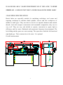
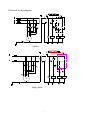
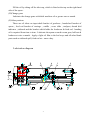
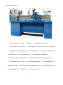
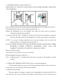
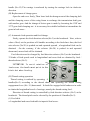
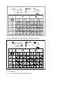
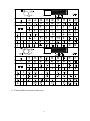
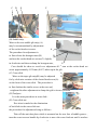
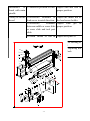
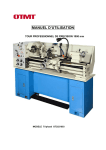
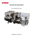
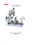
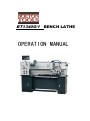
BT1340G/1 BENCH LATHE OPERATION MANUAL 1. GENERAL SAFETY RULES FOR POWER TOOLS DO NOT ATTEMPT TO OPERATE UNTIL YOU HAVE READ THOROUGHLY AND UNDERSTAND COMPLETELY ALL INSTRUCTIONS, RULES, ETC. CONTAINED IN THIS MANUAL FAILURE TO COMPLY CAN RESULT IN ACCIDENTS INVOLVING FIRE, ELECTRIC SHOCK OR SERIOUS PERSONAL INJURY. MAINTAIN OWNERS MANUAL AND REVIEW FREQUENTLY FOR CONTINUING SAFE OPERATION, AND INSTRUCTING POSSIBLE THIRD-PARTY USER. READ ALL INSTRUCTIONS 1.1 KNOW YOUR POWER TOOL For your own safety, read the owner’s manual carefully. Learn its application and limitations as well as the specific potential hazards peculiar to this tool. 1.2 GUARD AGAINST ELECTRICAL SHOCK BY PREVENTING BODY CONTACT WITH GROUNDED SURFACES. For example: Pipes, radiators, ranges, refrigerator enclosures. KEEP GUARDS IN PLACE AND IN WORKING ORDER . REMOVE ADJUSTING KEYS AND WRENCHES Form habit of checking to see that keys and adjusting wrenches are removed from tool before turning on tool. KEEP WORK AREA CLEAN. Cluttered areas and benches invite accidents. DON’T USE IN DANGEROUS ENVIRONMENT. Don’t use power tools in damp or wet locations, or expose them to rain. Keep work area well illuminated. KEEP CHILDREN AWAY. All visitors should be kept a safe distance from work area. MAKE WORKSHOP KID PROOF. With padlocks, master switch, or by removing starter keys. DON’T FORCE TOOL. It will do the job better and be safer at the rate for which it was designed. USE RIGHT TOOL Don’t force tool or attachment to do a job for which it was not designed. 1 1.2.9 WEAR PROPER APPAREL No loose clothing. Gloves, neckties, rings bracelets, or jewelry to get caught in moving parts. Nonslip footwear is recommended . Wear protective hair covering to contain ling hair. 1.2.10 ALWAYS USE SAFETY GLASSES Also use face or dust mask if cutting operation is dusty. Everyday eyeglasses only have impact – resistant lenses. They are not safety glasses. 1.2.11 SECURE WORK Use clamps or a vise to hold work when practical. It’s safer than using your hand and frees both hands to operate tool. 1.2.12 DON’T OVERREACH Keep your proper footing and balance at all times. 1.2.13 MAINTAIN TOOLS IN TOP CONDITION Keep tools sharp and clean for best and safest performance. Follow instructions for lubricating and changing accessories. 1.2.14 DISCONNECT TOOLS FROM POWER SOURCE Before servicing and when changing accessories such as blades , bits cutters or when mounting and re-mounting motor . 1.2.15 AVOID ACCIDENTAL STARTING Make sure switch is in “OFF” position before plugging in cord . 1.2.16 USE RECOMMENDED ACCESSORIES Consult the owner’s manual for recommended accessories. Use of improper accessories may be hazardous. 1.2.17 NEVER STAND ON TOOL Serious injury could occur if the tool is tipped or if the cutting tool is unintentionally contacted. 1.2.18 CHECK DAMAGED PARTS Before further use of the tool , a guard or other part that is damaged should be carefully checked to ensure that it will operate properly and perform its intended function. check for alignment of moving parts , binding of moving parts , breakage of parts , mounting , and any other conditions that may affect its operation . A guard or other part that is damaged should be properly repaired or replaced. 1.2.19 DIRECTION OF FEED 2 Feed work into a blade or cutter against the direction of rotation of the blade or cutter only . 1.2.20 NEVER LEAVE TOOL RUNNING UNATTENDED. TURN POWER OFF. Don’t Leave tool until it comes to a complete stop. The operation of any power tool can result in foreign objects being thrown into the eyes, which can result in severe eye damage . Always wear safety glasses or eye shields before using your Lathe . We recommend wide vision safety mask for use over spectacles , or standard safety glasses . 2.SAFETY RULES FOR LATHES Safety is a combination of operator common sense and alertness at all times when Lathe is being used . Study these safety rules and general safety rules before operating and retain for future use . 2.1 Wear eye protection . 2.2 Never attempt any operation or adjustment if proceedure is not understood . 2.3 Keep fingers away from revolving parts and cutting tools while in operation . 2.4 Never force cutting action . 2.5 Never perform an abnormal or little used operation without study and use of adequate blocks , jigs stops , fixtures ect . 2.6 Use of shop manual such as “ Machinery’s Handbook ” or similar is recommended for cutting speeds feeds and operation detail . 2.7 Do not remove drive cover while machine is in operation . Make sure it is always closed . 2.8 Always romove chuck key , even when machine is not in operation . 2.9 Do not attempt to adjust or remove tools when in operation . 2.10 Always keep cutters sharp . 2.12 Never use in an explosive atmosphere or where a spark could ignite a fire. 2.13 Always use identical replacement parts when servicing. 3 DO ALLOW FAMILIARILY (GAINED FROM FREQUENT USE OF YOUR LATHE) TO BECOME COMMONPLACE. A CARELESS FRACTION OF A SECOND CAN ALLOW FOR SEVERE INJURY. 3.MACHINE SPECIFICATION Bench lathes are especially suitable for machining workshops, tool rooms and repairing workshops to machine shafts spindles, sleeves and disc workpieces of middle or small types. They can also be used to cut imperial, diameter and module threads. And with compact construction and reasonable composition, they can cut very well. They are easy and reliable to operate, convenient to repair, high in efficiency, and low noise. Hardened with supersonic frequency heat-treatment. The bed sliding and the gears are wear-resisting. The apron have both the left hand and right hand type . Their construction is the same . It is optional. Overall measurement: 4 TECHNICAL DATA Capacity Dimension Swing Over Bed ------------------------------------------------- ----12.99"(330mm) Over Cross Slide ------------------------------ ------ --- ------7.68"(195mm) Through Gap -------------------------------------------------18.74" (476mm) Distance Between Centers------------------------------------------39-1/3"(1000mm ) Bed Width --------------------------------------------------------7-3/8"(187mm ) Length ----------------------------------------------------65-1/3"( 1658mm ) Height ---------------------------------------------------11-13/32"( 290mm ) Main Motor ------------------------------------------------------- --------------------2HP Headstock Spindle Bore ---------------------------------------------------------------1-1/4"(38mm) Nose --------------------------------------------------- D 1-4" ASA std.( ISO ) Taper in nose-------------------------------------------------------------M.T..5 Number Of Spindle Speeds------------------------------------------------------------8 Range Of Spindle Speeds -----------------------------------------------70-2000 r.p.m Carriage & toolpost Cross slide Width ------------------------------------------------------4-5/8"(118mm) Travel -----------------------------------------------------6-5/16"(160mm) Toolpost Width ---------------------------------------------------------------3"(76mm) Travel ------------------------------------------------------2-11/16"(68mm) Leadscrew Diameter ----------------------------------------------------7/8" ( 22mm ) Thread -------------------------------------------------8T.P.I. or 3mm pitch Diameter Of Feed rod ----------------------------------------------------3/4"(19mm) Max. section Of Cutting Tool -----------------------5/8"5/8"(16mm 16mm) Threads & Feeds Threads Imperial pitches --------------------------------------- 40 Nos. 4-112 T.P.I. Metric pitches ------------------------------------------23Nos. 0.25-11mm Longitudinal Feeds Imperial ------------------------- 0.002-0.0548"/rev Metric -------------------------- 0.091-2.553mm/rev Cross feeds Imperial --------------------------------- 0.00055 -0.015"/rev 5 Metric --------------------------------- 0.025-0.69 mm/rev Tailstock Quill Diameter ---------------------------------------1-1/4" (32mm) Travel -------------------------------------------------3-3/4"(95mm) Taper -----------------------------------------------------------M.T.3 Weights (NW/GW) -------------------------------------------------------869lb/1089lb (With machine stand) -------------------------------------------------------------1309lb Packing size (LWH)----------------------------- -----------75.59"*29.92"*29.92" 4.UNLOADING Unpack the wooden case first and use the bed clamping plates and eyebolts to sling the lathe. Position the saddle and tailstock along with the bed to keep the balance. Make sure not to hit the leadscrew, spindle or other long rods and handwheel, when the machine is unloaded. 4.1Cleaning Before operation and controls. Remove the anticorrosion coating from all uncovered machine parts, Use white spirit or kerosene (paraffin). Do not use lacquer thinner or other caustic solvents. Oil all bright machined surfaces immediately with lubricating oil after cleaning. Use heavy oil or grease on the change gears. 4.2 Setting up the machine Locate the machine on a solid foundation, (A concrete floor is the best for the machine), allowing sufficient area for easy work and maintenance. The machine may be used when it is free standing, but for maximum performance it should be bolted down with four M12 foundation bolts. Use an engineers precision level on the bedways to make further adjustment for level conditions. 4.3 Electrical supply Power should be supplied through a separate isolator, the input wires are connected to main terminals at the back of the headstock. Check that the operating voltage and frequency given on the type plate corresponds to the local mains voltage and frequency. Connect fuse between the power source and switch, earth with machine. Main motor rotation must be clockwise, viewed from the pulley end (spindle must be anti – clock wise by looking from tailstock end ) . In case that the motor is running in a wrong direction, interchange any two of the three phase lines. 6 Electrical wiring diagram 3 phases Single phase 7 SIGN NAME TYPE M Motor 3 phase Y90L-4 Single phase KM YC100L-4 AC magnetic contactor LC1-D129 (3 phase0 LC1-D259(single phase) KA1 Relay CA2-DN22 TC Transformer JBK3-63 SA1 Power switch HZ5B-10/2D009 SB1 Emergency stop button LA25-01ZS SB2 Job button LA25-10 HL Power indicator light AD11-30/20 5.LUBRICATION SYSTEM (A) Head stock Ensure that the head stock is filled to the level of the relevant oil sight glass with Tellus 32 of Shell oil. For exchanging the oil in headstock , remove all oil by taking off the drain plug , which is fitted at the bottom left hand end of the head stock , accessible after removal of the end cover and the change gears with swing frame . Open the headstock cover to fill the oil, check oil level weekly and change the oil 3 months after first use , then change it once a year . (B)Quick change gearbox The bearings and gears should be oiled daily from the top . Remove the cover to expose the filling nipples. (C)Apron Ensure that the apron is filled to the correct level of the oil sight glass with Tellus 32 of shell oil . Check the oil level weekly and first oil change after 3 months use , farther oil change once a year . For exchanging the oil in apron , drain away all oil by taking off the drain plug , which is fitted on the bottom of the apron . 8 Fill the oil by taking off the inlet cap, which is fitted at the top on the right hand side of the apron . (D) Change gears Lubricate the change gears with thick machine oil or grease once a month . (E) Other portions There are oil inlets on input shaft bracket of gearboxs , handwheel bracket of apron , feed rod bracket of carriage , saddle , cross slide , toolpost, thread dial indicator , tailstock and the bracket which holds the leadscrew & feed rod . handing oil is required from time to time . Lubricate the apron worm & worm gear, half nut & leadscrew twice a month . Apply a light oil film to the bed ways and all other blank parts such as tailstock quill, feed rod etc . once a day . Lubrication diagram 9 Lubrication table No. Lubrication parts Number of Oil lubricating points Date of Date of filling oil changing oil 1 1 32# Once a day 1 1 1 5 3 1 32# 32# 32# 32# 32# 32# Once a day Once a day Once a day 2 32# Once a day 3 2 32# 32# Once a day Once a day 2 3 4 5 6 7 8 9 10 Input shaft of gearbox Gearbox Headstock Apron Carriage Tool post Thread dial indicator Leadscrew Feed rod Tailstock Support seat First change after 3 months, then,once a year Operation symbols for operation Electrical Diametral pitch (Danger) thread Coolant Module pitch thread Imperial thread Half nut opened Metric thread Half nut closed Right-hand thread and longitudinal feed toward the Headstock side Left-hand thread and longitudinal feed toward the tailstock side Feeding (left figure) Threading (right figure) Cross feed engaged (upward) All feeds disengaged (central) Longitudinal feed Engaged (downward) 6.WORKING WITH MACHINE 10 Operation diagram 1.Forward/reverse switch 4.Four steps speed selector 2.Handle 3.Feed direction selector 5.Low/high speed selector 6.Knob component 7.Steady rest 8.Longitudinal traverse hand wheel 9.cross traverse hand wheel 10.Follow rest 11.Toolpost handle 12.Toolpost traverse handle 13.Tailstock quill clamping lever 14.Tailstock quill traverse hand wheel 15.Tailstock set-over screw 16.Thread dial indicator 17.Controlling lever 18.Machine stand 19.Thread cutting engagement lever 20.Feed axis selector 21.Controlling rod 22.Feed rod 23.Lead screw 11 6.1SPINDLE SPEED CONTROL (refer to operation diagram) A. Identification before operation (1) Ensure that lubrication has been carried out in accordance with the lubrication charts. (2) When rotating the spindle, it is mechanized to the gear box and apron. Check that the forward / reverse switch (No. 1) or the knob component(No.6)( when it is mounted by option ) is in the Stop position ; the feed axis selector (No.20) and the thread cutting engagement lever (No.19) are in diseneaged position . Under the circumstances, both the longitudinal traverse hand wheel (No.8) and the cross traverse hand wheel (No.9) can be easily operated by hand . B. Rotation of spindle Rotation of spindle is selected by the forward / reverse switch(No.1) . C. Speeds of spindle change The speeds of spindle are changed by means of HIGH / LOW speed selector (No.5) and four steps speed selector (No.4) . The spindle’s speed chart shows 4 steps speeds in both high and low speed position. We can choose a proper revolution by operating the speed selector according to the spindle’s speed chart . When the speed selector (No.5) is in the high position , we can get four speeds referring to the high speed portion of the graph . Transference of the spindle speeds should be made after the spindle rotation is completely stopped. (Engagement of the drive gears may be assisted by manually turning the chuck) D. Running in Alternatively a running – in procedure should be adopted as follow ; Make a low feed rate selection and run the machine light For 3 hours at 460 r .p .m Then for 2 hours at 755 r .p .m Then for 1 hour at 1250 r .p .m 12 6.2 SPINDLE NOSE (CAM LOCK D1-4”) MOUNTING OF CHUCKS, FACEPLATES AND OTHER SPINDLE MOUNTED ATTACHMENTS Ensure that the location faces on both nose and attachment are scrupulously cleaned. Check that all the cams are in the release position (fig . 1) Mount the attachment on to the spindle nose and lock each cam by turning it clockwise using the key provided. A reference line R1 (fig .1) should be scribed on each chuck or faceplate to coincide with the reference line R on the spindle nose. assists subsequent re-mounting . NOTE : For correct locking conditions each cam must tighten with its index line between the two vee marks on the nose (Fig .2) DO NOT INTER CHANGE CHUCKS OR OTHEY SPINDLE MOUNTING ITDMS BETWEEN LATHES WITHOUT GHECKING EACH CAM FOR CORRECT LOCKING TO ADJUST CAM LOCK STUDS Remove Lockscrew (B) Turn Stud (A) one full turn in or out as required Refit and tighten leadscrew (B) (fig . 3) Note : A datum ring (C ) is marked on each stud as a guide to the original or initial setting . 6.3 FEED AND THREAD SELECTION (refer to operation diagram) All feeds and threads are given on the feed and thread tables, fitted on the front of the end cover, by setting the feed selector handle. (A) Hand feed operation The movement of carriage is made by the longitudinal feed hand wheel(No.8), cross slide by the cross feed hand wheel(No.9) and tool post by the tool post feed 13 handle (No.12) The carriage is anchored by turning the carriage lock in clockwise direction. (B) Replacement of change gears. Open the end cover firstly, Then loose both the hexagon nut of the clamping bolt and the clamping screw of the swing frame to exchange the transmission shaft gear with another gear. And the change of driven gear is made by loosening the 120T and 127T gear shaft clamping nut . it is necessary for suitable backlash to intermediate the gears in both cases . (C) Automatic feed operation and feed change. Firstly, operate the feed direction selector(No.3) at the headstock . Next, select a value of feed, set the positions of 4 handles according to the feed chart. then, the feed axis selector (No.20) is pushed out and operated upward , a longitudinal feed can be obtained . On the contrary, if the selector (No.20) is pushed in and operated downward, across feed will be obtained . Feed direction can be changed by feed direction selector (No.3) at the headstock . 32 kinds of feed speeds each in longitudinal and cross feed are obtained by feed / thread selector (No.2). * *ATTENTION: To avoid rotation of the lead screw, the handle must point to the black dot when feeding. (D) Thread cutting operation Thread cutting is realized by operating 4 handles(No.2) according to the thread chart, and operating the thread cutting engagement lever (No. 19) downward . It should be engaged with leadscrew in order to obtain the longitudinal travel of carriage, namely the thread cutting feed . Direction of thread cutting is controlled by feed direction selector (No.3) at the headstock . The thread pitch can be selected by the position of 4 handles(No.2). (1) Feed table a. Longitudinal and cross feed table in imperial lead screw . 14 b. Longitudinal and cross feed table in metric lead screw. (2) Thread table a. Thread table for imperial lead screw. 15 b. Thread table for metric lead screw. 16 (E)Threading dial indicator Threading dial indicator (No.16) is installed on the right hand side of apron. The indicator is used for thread cutting to engage with lead screw . To cut threads on the chart, close the lead screw nut at the appointed line of the dial according to the indicator chart, Ensure the appropriate dial line coincide exactly with fixed point each pass . For minimum wear the thread dial indicator should be disengaged, swinging the 17 gear of mesh with the lead screw tightly when out in use. a. IMPERIAL THREADS ON IMPERIAL LEADSCREW MACHINES OR METRIC THREADS ON METEIC LEADSCREW MACHINES For these threads it is recommended that the thread dial indicator be used this allows the half nut of lead screw to be engaged at the end of each thread cutting pass, provided that are reengaged in accordance with the indicator table mounted on the left hand side of the apron . b. IMPERIAL THREADS ON METRIC LEADSCREW MACHINES OR METRIC THREADS ON IMPERIAL LEADSCREW MACHINES AND DIAMETRAL PITCH, MODULE PITCH THREADS ON IMPERIAL OR METRIC LEADSCREW MACHINES For these threads the half nut is kept engaged throughout the cutting of any one thread. This involves reversing the whole drive by means of the spindle forward /reverse switch (No. 3 ) at each end of the thread cutting pass while at the same time relieving or increasing the cut as required . 7.LATHE ALIGNMENT When the lathe is installed and ready for use , it is recommened to check the machine alignment before starting work . Aligment and leveling should be checked regularly to ensure continued accuracy. (A) Headstock If headstock appears that the alignment is not correct any more , proceed as fallows : Take a steel bar with a diameter of appr.50mm and a length of appr.200mm. Span it in the chuck without using the center. Then cut off a chip over a length of 150mm and measure the difference in A and B . To correct a possible difference, loosen the screws (E,F) clamping the heastock on the bed . Adjust the headstock with set screws (C,D) . Tighten all screws and repeat the above procedure until all measurings tally. The lathe will be cutting correctly. 18 C D E F (B) Saddle strip Wear on the rear saddle gib strip (A) may be accommodated by adjustment of the socket head set screws . A The procedure for adjustment is to first release the hexagon nuts (B) B and turn the socket head set screws(C) slightly in clockwise and then reclamp the hexagon nuts, Care should be taken to avoid over adjustment 45 C 0 turn at the socket head set screw approximately 0.125mm (0.05") taken up in the gib. (C) Cross slide A Wear on the taper gib strip(B) may be adjusted B for by clockwise rotation of the slotted head screw(A) on the front of the cross slide . The procedure is to first slacken the similar screw at the rear end, retighten this after adjustment to clamp the gib in its new position. (D) Toolpost It is the same procedure as cross slide . (E) Cross slide nut Provision is made for the elimination of back lash in the cross slide nut . the procedure for adjustment being as follows . Take off the anti-dust plate which is mounted on the rear face of saddle groove , turn the cross traverse handle by clockwise to move the cross feed nut until it reaches 19 the end edge of the feed rod . Turn the socket head cap screw in a clockwise direction as require. Care should be taken to avoid over adjustment ; every 45 0 turn at the socket head cap screw represents approximately 0.125mm (0.05") taken up of back lash . (F) Cross slide and toolpost Toolpost is carried on a rotatable swivel table fitted as standard onto the cross slide, and the top of cross slide is graduated both - 45 0 ~ 0 and 0 ~ 45 0 for accurate indexing of swivel table. Handle dials are graduated in Imperial or Metric division to suit the operating feed screw and nut fitted. (G) Tailstock Tailstock can be set over for the production of shallow tapers or for realignment by means of the tailstock set – over screw which are mounted in each slide of the tailstock body, a similar but location screw is fitted in the rear face of the body . Set – over adjustment is made as follows : Unclamp the tailstock by operating the clamp lever downward . Slacken the rear location screw . Then alternatively slacken one set – over screw and tighten the other until the required setting is achieved . Tighten the rear location screw and the set – over screw which is slackened before, and reclamp the tailstock. The quill of tailstock is locked by operating the quill clamping lever. 8.PREVENTIVE MAINTENANCE 8.1 DAILY INSPECTION In principle the daily. Inspection of lathe is carried out on basis of each shift. The inspection work according to the following item 1.1 1.1 Check before starting the motor. 1) Clean-up of machine: dust, chips and other articles should be removed from sliding surface of machine to make the rotating or sliding parts performing easy and smoothly. All other static parts be often also cleaned to avoid the corrosion. 2) Greasing and oiling : regular oiling should be done every day (see 20 lubrication plan sheet) to keep the machine properly lubricated. 3) Check all the running parts not too tight, or loose. Bearing of headstock, longitudinal and cross feed, tool holders etc would be exmined and adjusted by hand or proper fitness. 4) Check the sensitivity & reliability of all manual control levers: To try the speed change rate function of headstock feeds and apron in gear box and inspect their starting, stopping and forward & reverse action whether they are sensitive and reliable or not. 5) Fixture and fig of headstock, tailstock and tool holder tight clamping between tailstock and bed surface, close running fit of spindle in tailstock, clamp bolts of tool holder, and figs on headstock. 8.2 Check after starting the machine. 1) To check electrical control system: Try to put “on” and “off” button and examine the sensitiveness of starting, stopping and pilot lamp strictly. 2) The sensitivity and reliability of mechanical control device: control levers for forward and reverse main spindle, automatic feeds and threads change should be sensitive and reliable. Automatic control devices for longitudinal and cross feed, gear change, threads change, carriage, and spindle direction change should be accurate also. 3) Limitation of noise and vibration: when starting max. speed of headstock spindle on no loading basis, check the noise and vibration whether they are over specified limit or not. 4) Coolant system: check the quantity of coolant oil and start the oil pump for inspecting its function and leakage. 5) Lubricating system. Examine all lubricating system carefully and ensure all flowing line without obstacles. 8.3 Caution during operation: 1) Temperature of bearing. Tough the main bearing by hand and feel the temperature is normally or not. 2) Temperature of motor: 21 To feel the temperature of motor bearing at the case of full load. 3) Noise and vibration: If you find the noise and vibration of the machine are abnormal or irregular. Stop the machine immediately for inspection and adjustment. 4) Quality of products: If you discover the quality of products is out of limit, stop the machine at once for finding the causes of defects. 5) Safety affairs: a. Must stop operation when you leave the machine. b. When changing main spindle speed or feeding speed stop running first. c. All tools and products are strictly not allowed to be left on sliding surface of bed. 8.4 Check after operation 1) Cleaning and collection of all tools: All tools should be kept clean first then put back to original position. 2) Proper position of tailstock, carriage & tool holder: Tailstock, carriage & tool holder should be placed to proper position: 3) Clean-up machine: All of the oily matters, chips etc, on the machine should be removed completely and put a thin lubricating oil on the sliding surface of machine to prevent the corrosion. 8.4.1WEEKLY INSPECTION 1) Lubricating system: Clean-up the whole lubricating system and replenish with fresh lubricating oil. 2) Cooling system: Clean-up the whole cooling system and replenish with new cooling fluid. 3) Transmission system: Check the damage of rubber V-belt and readjust the tensile strength of V-belt. 8.4.2MONTHLY INSPECTION: 1) Dismantle and clean all the dust, chips and foreign matter from moving parts. 22 2) Electrical system: Carefully examine the connection of all electrical wires, terminals and switches, which occasionally have been damaged by chips or others. 8.4.3SEMI-YEARLY INSPECTION: 1) Change oil in gear box: Remove the used oil from gear box of headstock, feed and replenish with fresh oil. 2) Check the wear and tear of all gears in gears and packing: Inspect the damage of all gears in various box. Spindle and bearings, and packing. Repair or replace it if necessary. 3) Check the clearance fit of complicated feed mechanism: Check the clearance fit between feeding screw lever and nut and main screw spindle and nut whether they are right or not. 4) The stability of machine body: Tighten up the foundation bolts of machine body to the ground and make the body stable. 8.4.5YEARLY INSPECTION: 1) Positioning and leveling: According to the inspection regulation, recheck the positioning and leveling after once year service. 2) Inspection for accuracy: According to the regulation, inspection work for accuracy should be rechecked, if the accuracy is over specified limit, the adjustment or alignment will be done accordingly. 3) Bearing inspection: Reexamine the insulating materials and clearance fit & lubrication of all bearings. 4) Inspection for appearance: a. If paint is peeled off, repaint it with the same color. b. Check the exposed parts whether they have been damaged, corroded, or deformed, repair or replace them if necessary. 23 9.TROUBLE SHOOTING TROUBLE PROBABLE CAUSES Overheat headstock bearing REMEDY of 1.Oil level in headstock is Check the oil level and too low or too high. replenish or discharge the oil to the proper level. 2.Quality and viscosity of oil Replace the oil with is wrong. recommended one. 3.Oil is too dirty Replace oil. 4.Oil hole in bearing Remove the dirt from obstructed by dirt. the oil hole. 5.Bearing obstructed by dirt Clean the bearing and renew it. 6.Badly worn bearing. Replace bearing. 7.Bearing in its not improper Dismantle and position. reassemble it. 8.Bent or sprung main Replace main spindle. spindle. 9.Too much end thrust. Adjust thrust nut. Oil leakage from 10.Plug of drain not tightly. Remove, recement gear box. threat; replace and tighten. 11.Headstock cracking. Repaired special welding. 12.Leakage from overflow Tighten cover screw or headstock cover. replace gasket. 13.Leakage from overflow Replace oil ring. spindle bearing house. Excess noise of 14.Badly worn bearing. Replace bearing. vibration of 15.badly worn gear. Replace gear. machine 16.Bent or sprung shaft. Replace shaft. 17.Lose of foundation bolts. Tight foundation bolts. 24 Chatter 18.Clamp of workpiece in from loose status. 19.Spindle bearing thrust too loose. 20.Headstock is not tight with bedway. 21.Excess clearance between carriage 22.Excess clearance in cross or compound slide. 23.Cutting angle of cutting tool is not correct. 24.Edge of cutting tool has been worn-out. 25.Weak of tool shank and too long for extension. 26.Tool fixed to holder not tight enough. 27.Unbalances of workpiece or chuck when high speed revolution. 28.Front point of cutting tool not in correct position. Bending when 29.Feed value too large. long workpiece 30.Workpiece too thin or too cutting long. Accuracy of 31.Accuracy fails in product fails. machining. Tighten clamp. Adjust bearing thrust. Tighten headstock screw. Adjust carriage back clamp. Adjust carriage back clamp. Regrind tools to cutting angles. Regrind cutting tool. Replace with rigid tools or reset the tools. Tighten tool again. Balance or reduce spindle speed revolution. Reset cutting tool. Reduce feed value size. Use follow rest and adjust position of tool. Check the accuracy of correlation between products and machine. Uneasy to hold 32.Set spring broken or too Adjust adjusting screw gear change weak. or replace the spring. lever. 25 Misalliance of 33.Incorrect position of cam. chuck with main spindle. Uneasy to cut the 34.Excessive clearance of thread lead screw in axial direction. 35.Excessive clearance between saddle or cross slide or cross slide and tool post slide. 36.Worn thread or nut in cross slide or tool post slide. 37.Excessive clearance of handwheel. Tailstock is 38.Clamp handle lever too uneasy to clamp long or too short. with bed stably. 26 Adjust cam and lock in proper position. Adjust the thrust nut of the lead screw holder. Adjust slide gib to proper position. Adjust or replace it. Adjust the set bushing of handwheel. Adjust the adjusting nut of clamp block. 27 Bed Assembly Index No. 1 2 3 4 5 6 7 8 9 10 11 12 13 14 15 16 17 18 19 20 21 22 23 24 25 26 27 28 29 30 31 32 33 34 35 36 37 38 39 40 41 42 43 44 Part No. GB/T70 GB/T41 GB/T881 CZ1340G-01-015 GB/T77 CZ1340G-07-028 GB/T5780 CZ1340G-01-016 GB/T117 GB/T70 CZ1340G-01-017 CZ1340G-07-058 CZ1340G-01-024 CZ1340G-01-024 CZ1340G-01-024 GB/T70 GB/T117 GB/T1155 GB/T70 GB/T119 CZ1340G-01-025 CZ1340G-01-030 CZ1340G-01-028 CZ1340G-01-029 GB/T2089 CZ1340G-07-057 GB/T6172 GB/T79 GB/T879 CZ1340G-01-026 JB/T7271.5 CZ1340G-01-018 CZ1340G-01-019 CZ1340G-01-020 CZ1340G-01-021 GB/T78 CZ1340G-01-006 GB/T77 GB/T1096 GB/T5780 GB/T97 GB/T5780 GB/T96 Description Hex Socket Cap Screw Hex Nut Pin Gap Set Screw Bed Hex Cap Bolt Rack Pin Hex Socket Cap Screw Rack Bracket Plug Plug Plug Hex Socket Cap Screw Pin Oil Ball Hex Socket Cap Screw Pin Handle Collar Key Brake Ring Spring Bracket Hex Nut Screw Pin Handle Knob Lead screw Feed Rod Shaft Collar Set Screw Pulley Screw Key Hex Cap Bolt Washer Motor Hex Cap Bolt Washer 28 Size M10×40 M8 8×75 M10×16 M12×50 5×25 M6×20 M8×55 6×70 8 M6×16 8×25 1×6×25 M8 M8×28 3×16 AM10×50 M6×10 8×40 M8×25 10 2HP(1.5KW) M10×35 10 Qty 4 2 2 1 1 1 6 1 6 8 2 1 1 1 1 2 2 2 2 1 1 1 1 1 3 1 2 2 1 1 1 1 1 1 1 1 1 1 1 4 4 1 3 3 Index No. 45 46 47 48 49 Part No. CZ1340G-01-005 CZ1340G-02-001 CZ1340G-00-005 CZ1340G-02-002 CZ1340G-02-002 Description Motor Mounting Plate Lock Nut Cover Screw Screw 29 Size Qty 1 2 1 1 1 Headstock Assembly Index No. Part No. Description Size 1 2 3 4 5 6 7 8 9 10 11 12 13 14 15 16 17 18 19 20 21 22 23 24 25 26 27 28 29 30 31 32 33 34 35 36 37 38 39 40 41 42 43 44 GB/T70 CZ1340G-02-009 CZ1340G-02T01-001 CZ1340G-02-008 GB/T77 CZ1340G-02-031 GB/T7757.2 GB/T276 CZ1340G-02-030 GB/T1096 CZ1340G-02-032 CZ1340G-02-029 CZ1340G-02-028 CZ1340G-02-027 CZ1340G-02-067 CZ1340G-02-065 CZ1340G-02-066 CZ1340G-02-064 CZ1340G-02-063 GB/T70 CZ1340G-02-026 GB/T7757.2 GB/T276 GB/T1096 CZ1340G-02-025 GB/T1096 GB/T894.1 CZ1340G-02-022 CZ1340G-02-021 CZ1340G-02-019 GB/T1096 CZ1340G-02-018 CZ1340G-02T01-004 GB/T41 GB/T5781 CZ1340G-02-010 GB/T9877.1 CZ1340G-02-017 CZ1340G-02-016 GB/T70 GB/T1171.1 CZ1340G-02-015 CZ1340G-02-013 GB/T70 Screw Screw Cover Gasket Screw Plug O-Ring Bearing Gear Shaft Key Gear Gear Gear Collar Gear Gear Washer Gasket Rear Cover Screw Plug Bearing Bearing Key Shaft Key C-Clip Gear Gear Gear Key Gear Main Casting Hex Nut Screw Oil Pipe Oil Seal Gasket Cover Screw V-Belt Pulley Washer Screw M6×16 31 M6×8 41.3×3.1 6204/P6 6×56 53T 34T 26T 43T 51T M4×12 34.7×3.1 6203/P6 6×120 5×20 35 38T 46T 29T 5×50 21T M8 M8×50 B20408B M6×16 A787 M8×20 Qty. 6 1 1 1 5 1 1 3 1 2 1 1 1 1 1 1 1 1 1 3 1 1 1 1 1 1 1 1 1 1 1 1 1 2 2 2 1 1 1 3 2 1 1 1 Index No. Part No. Description Size 45 46 47 48 49 50 51 52 53 54 55 56 57 58 59 60 61 62 63 64 65 66 67 68 69 70 71 72 73 74 75 76 77 78 79 80 81 82 83 84 85 86 87 88 89 GB/T70 CZ1340G-02-011 CZ1340G-02-012 GB/T279 Gb/T894.1 CZ1340G-02-036 CZ1340G-02-033 GB/T1096 CZ1340G-02-037 GB/T894.1 GB/T297 CZ1340G-02-062 CZ1340G-02-005 CZ1340G-02-004 GB/T70 CZ1340G-02-002 GB/T810 CZ1340G-02-001 CZ1340G-02-003 GB/T1096 GB/T1096 CZ1340G-02-034 CZ1340G-02-035 GB/T2089 GB/T70 JB/T7941.1 GB/T70 GB/T97.1 GB/T93 GB/T77 GB/T894.1 GB/T893.1 CZ1340G-02-059 GB/T276 GB/T7757.2 CZ1340G-02-061 CZ1340G-02-045 CZ1340G-02-051 CZ1340G-02-055 GB/T7757.2 CZ1340G-02-053 CZ1340G-02-052 GB/T70 GB/T1096 CZ1340G-02-054 Screw Front Cover Gasket Bearing C-Clip Gear Gear Key Gear C-Clip Bearing Collar Gasket Rear Cover Screw Screw Lock Nut Lock Nut Spindle Key Key Cam Pin Spring Screw Oil Sight Screw Washer Washer Screw C-Clip C-Clip Gear Bearing O-Ring Shaft Gear Washer Collar O-Ring Gasket Collar Screw Key Shaft M6×25 32 30212/P5 72 74T 37T 8×18 37T 50 30210/P5 M6×25 M50 8×90 6×40 0.6×3×10 M8×20 A20 M10×40 10 10 M12×12 20 42 30T 16004/P6 19.8×2.65 37T 26.3×3.1 M5×16 6×50 Qty. 4 1 1 1 1 1 1 1 1 1 1 1 1 1 3 1 2 1 1 1 1 3 3 3 3 1 4 4 4 1 3 2 2 1 1 1 1 2 1 1 1 3 1 1 Index No. Part No. Description 90 91 92 93 94 95 96 97 98 99 100 101 102 103 GB/T879 GB/T1096 GB/T7757.2 CZ1340G-02-056 GB/T10708.3 CZ1340G-02-057 GB/T97.1 GB/T41 CZ1340G-02-024 GB/T7757.2 CZ1340G-02-020 GB/T879 CZ1340G-02-023 CZ1340G-02-040 Pin Key O-Ring Washer Oil Seal Gear Washer Nut Shift Lever O-Ring Shift Fort Pin Shaft Gear 33 Size 3×10 ×18 13.8×3.1 24×32×5 40T 12 M12 11.8×1.8 5×32 51T Qty. 1 1 1 1 1 1 1 1 1 2 1 2 1 1 31 Inlaid Block Assembly Index No. Part No. Description 1 2 3 4 5 6 7 8 9 10 11 12 13 14 15 16 17 18 19 20 21 22 23 24 25 26 27 28 29 30 31 32 33 34 35 36 37 38 39 CZ1340G-02-046 GB/T308 GB/T2089 GB/T77 GB/T71 CZ1340G-02-068 JB/T7271.5 CZ1340G-02-044 CZ1340G-02-043 GB/T308 GB/T2089 GB/T77 CZ1340G-02-058 GB/T77 GB/T2089 CZ1340G-02-060 GB/T70 CZ1340G-02-042 GB/T894.1 GB/T818 CZ1340G-02T01-006 CZ1340G-02T01-005 GB/T7757.2 GB/T1096 CZ1340G-02T01-002 GB/T7757.2 CZ1340G-02T01-003 CZ1340G-02T01-008 GB/T819 CZ1340G-02-038 CZ1340G-02-049 GB/T879 CZ1340G-02-050 CZ1340G-02T01-007 GB/T7757.2 GB/T7757.2 CZ1340G-02-047 GB/T819 GB/T70-85 Handle Body Steel Ball Spring Screw Screw Handle Lever Sleeve Handle Block Handle Body Steel Ball Spring Screw Handle Screw Spring Handle Screw Hub C-Clip Screw Name Plate Inlaid Block O-Ring Key Revolving Sleeve O-Ring Gear Shaft Block Screw Shift Fork Shift Fork Spring Pin Shaft Housing Shaft O-Ring O-Ring Shift Hub Screw Screw 31 Size 5 0.6×3×18 M6×8 M6×12 BM8×40 6 0.9×4×20 M8×10 M8×8 0.9×4×7 M6×20 30 M4×6 25.7×2.65 5×16 13.8×1.8 M4×12 4×18 7×1.8 16×2.65 M4×8 M10×40 Qty. 1 1 1 1 1 1 3 1 1 2 1 1 1 1 1 1 2 1 1 6 1 1 1 2 1 1 1 1 1 1 1 1 1 1 1 1 1 2 4 32 Gearbox Assembly Index No. 3 4 5 Part No. GB/T70 CZ1340G-03-007 CZ1340G-07-008 Description Screw Shaft Cover Gear(30T,54T,56T,57T, 6 7 8 9 10 11 12 13 14 15 16 17 18 19 20 21 22 23 24 25 26 27 28 29 30 31 32 33 34 35 36 37 38 39 40 41 42 43 44 45 46 47 CZ1340G-07-013 GB/T1096 GB/T1096 GB/T894 GB/T276 CZ1340G-07-018 CZ1340G-07-021 GB/T70 CZ1340G-07-022 GB/T117 GB/T70 CZ1340G-07-009 GB/T1155 CZ1340G-07-010 GB/T276 CZ1340G-07-012 GB/T894 CZ1340G-07-011 GB/T276 CZ1340G-07-001 GB/T879 GB/T70 CZ1340G-07-049 CM1224C-03-034 GB/T894 CZ1340G-07-053 CZ1340G-07-052 CZ1340G-07-051 GB/T1096 CZ1340G-07-005 CZ1340G-07-004 CZ1340G-07-015 GB/T1096 CZ1340G-07-006 CZ1340G-07-007 CZ1340G-07-014 GB/T77 CZ1340G-07-059 CZ1340G-07-047 CZ1340G-07-045 CZ1340G-07-044 CZ1340G-07-002 Shaft Key Key C-Clip Bearing Gasket Cover Screw Shaft Pin Screw Cover Oil Ball Gasket Bearing Cover C-Clip Gear Bearing Casting Pin Screw Collar Oil Cover C-Clip Gear Gear Gear Key Cover Gasket Shaft Key Gear Gear Gear Screw Cover Gear Gasket Cover Gear Size M6×16 60T,63T,66T,69T,7 8T) 5×18 5×45 20 6004 M5×12 3×32 M6×20 6 6203 16 24T,16T 6202 5×20 M8×65 26 24T 28T 4×22 4×55 24T 16T 32T M5×16 32T 16T 33 Qty. 1 1 9 1 1 1 5 2 1 1 18 1 2 3 1 1 1 1 1 2 1 9 1 2 2 3 1 2 2 2 2 2 3 3 1 1 1 1 1 2 1 1 1 1 1 Gearbox Assembly Index No. 48 49 50 51 47 48 49 50 51 52 53 54 55 56 57 58 59 60 61 62 63 64 65 66 67 68 69 70 71 72 73 74 75 76 77 78 79 80 81 82 83 84 85 86 87 88 89 Part No. CZ1340G-07-003 GB/T70 GB/T3452.1 D97-4-20 CZ1340G-07-002 CZ1340G-07-003 GB/T70 GB/T3452.1 D97-4-20 GB/T70 GB/T117 GB/T9877.1 GB/T1096 CZ1340G-07-043 CZ1340G-07-056 CZ1340G-07-055 CZ1340G-07-054 CZ1340G-07-016 CZ1340G-07-027 GB/T41 GB/T75 CZ1340G-07-024 CZ1340G-07-026 CZ1340G-07-023 CZ1340G-07-029 CZ1340G-07-025 CZ1340G-07-030 CZ1340G-07-037 CZ1340G-07-034 CZ1340G-07-033 GB/T77 CZ1340G-07-038 GB/T65 LXW5-11G2 CZ1340G-07-048 CZ1340G-07-017 CZ1340G-07-019 CZ1340G-07-050 GB/T1096 CZ1340G-07-020 CZ1340G-07-046 GB/T117 CZ1340G-07-039 GB/T70 GB/T3452.1 CZ1340G-07-035 GB/T879 Description Shaft Screw O-Ring Locking Connector of Tube Gear Shaft Screw O-Ring Locking Connector of Tube Screw Pin Oil Seal Key Shaft Gear Cover Gear Gear Shaft Nut Screw Slip Fitting Rack Slip Fitting Slip Fitting Rack Rack Gear Shaft Rack Gasket Screw Engaging Arm Screw Switch Lid Gear Cover Shaft Key Gear Shaft Pin Cover Screw O-Ring Washer Pin 34 Size M10×16 9.5×1.8 16T M10×16 9.5×1.8 M8×25 6×25 28×40×7 5×20 32T 30T 28T M5 M5×16 M6×10 M4×55 30T 4×145 16T 3×25 M5×25 6.9*1.8 4×40 Qty. 1 1 5 1 1 1 1 5 1 2 2 1 1 1 1 1 1 1 2 4 4 1 1 1 2 1 1 4 1 1 4 1 2 2 1 1 1 1 1 1 1 1 1 8 4 4 4 Index No. 90 91 92 93 94 95 96 Part No. GB/T879 GB/T1160.1 CZ1340G-07-036 GB/T308 GB/T2089 GB/T77 CZ1340G-07-041 Description Pin Oil Sight Glass Handle Body Steel Ball Spring Screw Panel 35 Size 4×25 20 6.5 1×5×20 M8×10 Qty. 2 1 4 4 4 4 4 36 Apron Assembly Index NO. Part NO. Description Size Qty 1 2 3 4 5 6 GB/T5780 CZ1340G-04-030 CZ1340G-04-016 GB/T1096 CZ1340G-04-015 GB/T3452.1 Screw Washer Gear Key Shaft O-Ring M6*10 1 1 1 1 1 1 7 8 9 10 11 12 13 14 15 16 17 18 19 20 21 22 23 24 25 26 27 28 29 30 31 32 33 34 35 36 37 38 39 40 41 42 43 44 45 46 CZ1340G-04-013 GB/T879 CZ1340G-04-004 GB/T879 CZ1340G-04-005 CZ1340G-04-047 GB/T70 CZ1340G-04-001 GB/T3452.1 GB/T5781 CZ1340G-04-029 CZ1340G-04-002 GB/T1096 JB/T7940.4 CZ1340G-04-003 GB/T70 GB/T78 CZ1340G-04-048 CZ1340G-04-045 CZ1340G-04-046 GB/T70 CZ1340G-04-043 CZ1340G-04-044 GB/T4141.14 CZ1340G-04-009 CZ1340G-04-008 GB/T70 CZ1340G-04-007 GB/T308 GB/T1239.2-89 GB/T77 CZ1340G-04-022 GB/T70 GB/T879 CZ1340G-04-006 CZ1340G-04-028 GB/T119 CZ1340G-04-024 GB/T119 CZ1340G-04-027 Gear Pin Gear Shaft Pin Gear Bracket Screw Apron box O-Ring Screw Cover Gear Shaft Key Oil Ball Dial seat Screw Screw Dial Hand wheel Washer Screw Screw Handle Handle Handle rod Shift lever Screw Box Steal Ball Spring Screw Cover Screw Spring Pin Cover Gear Pin Bushing Pin Gear 40T 5H30 13T 5*30 60T 37 22T 5*12 20*2.4 M6*16 12*2.4 M12*25 14T A5*18 8 M6*25 M5*6 M6*16 M8*16 M625 5 0.8*4*20 M6*6 M6*12 5*20 63T B8*25 A3*25 40T 1 1 1 1 1 1 1 1 1 1 1 1 1 1 1 3 1 1 1 1 1 1 1 1 1 1 3 1 2 2 2 1 4 2 1 1 3 1 1 1 Index NO. Part NO. Description Size Qty 47 48 49 50 51 52 53 54 55 56 57 58 59 60 61 62 63 64 65 66 67 68 69 70 71 72 73 74 75 76 77 78 79 80 81 82 83 84 GB/T77 CZ1340G-04-023 JB/T7941.1 CZ1340G-04-041 CZ1340G-04-033 CZ1340G-04-026 GB/T70 CZ1340G-04-012 CZ1340G-04-011 CZ1340G-04-010 GB/T70 GB/T83 GB/T77 CZ1340G-04-034 CZ1340G-04-018 GB/T5781 GB/T79 GB/T6170 GB/T5781 CZ1340G-04-019 GB/T6170 GB/T77 CZ1340G-04-021 GB/T119 CZ1340G-04-017 CZ1340G-04-020 CZ1340G-04-042 GB/T4141.14 GB/T6170 GB/T93 CZ1340G-04-035 CZ1340G-04-036 CZ1340G-04-037 CZ1340G-04-040 CZ1340G-04-039 GB/T70-85 CZ1340G-04-038 GB/T827-86 Screw Gear Oil Sight Oil Plug Bushing Shaft Screw Shaft Gear Washer Screw Screw Screw Bar Half Nut Bolt Screw Nut Screw Nut seat Nut Screw Gib Pin Shaft Handle Seat Handle Rod Knob Nut Washer Bushing Gear Bushing Bushing Theading dial body Screw Theading dial shaft Rivet M5*12 30T 12 2 1 1 1 1 1 2 1 1 1 1 1 1 1 1 2 2 2 3 1 3 3 1 2 1 1 1 1 1 1 1 1 1 1 1 1 1 1 85 86 87 88 JB/T7940.4 CZ1340G-04-014 CZ1340G-04-031 CZ1340G-04-032 Oil cup Worm Key Pin 6 38 M5*12 18T M6*10 M5*5 M6*10 M6*12 M6*35 M6 M5*16 M5 M5*16 6*12 M8*40 M8 8 M8*50 3*8 1 1 1 1 39 Saddle and Cross Slide Assembly Index NO Part NO Description 1 2 3 4 5 6 7 8 9 10 11 12 13 14 15 16 17 18 19 20 21 22 23 24 25 26 27 28 29 30 31 32 33 34 35 36 37 38 39 40 41 42 43 44 45 46 47 48 49 50 JB/T4141.5 CZ1340G-05-023 CZ1340G-05-022 CZ1340G-05-021 CZ1340G-05-038 GB/T77 GB/T70 GB/T301 CZ1340G-05-020 JB/T7940.4 GB/T5781 CZ1340G-05-013 CZ1340G-05-039 GB/T823 CZ1340G-05-013 CZ1340G-05-014 GB/T70 GB/T118 CZ1340G-05-006 CZ1340G-05-007 GB/T6170 GB/T71 GB/T5781 JB/T7940.4 CZ1340G-05-019 GB/T1096 CZ1340G-05-018 GB/T68 GB/T1096 CZ1340G-05-008 CZ1340G-05-010 GB/T70 GB/T301 CZ1340G-05-003 GB/T93 GB/T70 CZ1340G-05-002 CZ1340G-05-001 GB/T858 GB/T810 CZ1340G-05-032 CZ1340G-05-031 CZ1340G-05-039 CZ1340G-05-017 GB/T70 CZ1340G-05-011 JB/T7940.4 GB/T78 CZ1340G-05-004 CZ1340G-05-005 Handle Screw Washer Handle Wheel Dial Ring Screw Screw Bearing Hub Oil Ball Screw Strip Saddle Screw Plate Plate Screw Taper Pin Plate Plate Nut Screw Screw Oil Ball Sleeve Key Gear Shaft Screw Key Lead Screw Lead Nut Screw Bearing Bearing Housing Spring Washer Screw Anti-dust Cover Sleeve Washer Nut Set Screw Gib Cross Slide T-Bolt Screw Sleeve Oil Ball Screw Metal piece Gib 40 Size M8*63 M6*8 M6825 51104 6 M8*20 M4*12 M8*30 A8*40 M6 M6*16 M8*25 8 4*4*20 M3*6 55*30 M6*16 51101 8 M8*25 12 M12 M8*16 8 M8*10 M8*63 QTY 1 1 1 1 1 1 2 1 1 1 4 2 1 8 2 2 4 2 2 2 4 4 3 2 1 1 1 1 1 1 1 1 2 1 2 2 1 1 1 1 2 1 1 2 1 1 3 1 1 2 41 Tool Post Assembly Index NO Part NO Description Size QTY 1 2 3 4 5 6 7 8 9 10 11 12 13 14 15 16 17 18 19 20 21 22 23 24 25 26 27 28 29 JB/T7271.5 JB/T7271.6 CZ1340G-05-026 CZ1340G-05-024 GB/T83 CZ1340G-05-029 CZ1340G-05-025 GB/T78 CZ1340G-05-030 GB/T2089 CZ1340G-05-028 JB/T7940.4 GB/T78-85 GB/T301 CZ1340G-05-034 GB/T70 GB/T6173 GB/T78 CZ1340G-05-036 GB/T117 GB/T72701.9 CZ1340G-05-035 CZ1340G-05-033 GB/T6170 GB/T97.2 CZ1340G-05-016 CZ1340G-05-015 CZ1340G-05-027 GB/T73 Knob Handle Rod Lock Nut Washer Screw Post Base Screw Screw Stop Spring Top Slide Oil Ball Screw Bearing Collar Screw Nut Screw Dial Ring Pin Handle Lead Screw Lead Nut Nut Washer Set Screw Gib Swivel Slide Screw M1050 1 1 1 1 8 1 1 2 1 1 1 3 1 2 1 2 2 1 1 1 1 1 1 2 2 2 1 1 1 42 M1040 M610 0.4418 6 M610 51101 M620 M121 M66 A316 825 M8 M88 43 Tailstock assembly Index No. Part No. Description 1 2 3 4 5 6 7 8 9 10 11 CZ1340G-06-020 CZ1340G-06-017 CZ1340G-06-018 GB/T879 GB/T41 GB/T79 CZ1340G-06-019 JB/T7271.5 CZ1340G-06-012 JB/T7271.5 CZ1340G-06-013 Base Screw Collar Pin Nut Screw Shaft Knob Lever Knob Screw 12 CZ1340G-06-015 Shaft 1 13 14 15 16 17 18 19 20 21 22 23 24 25 26 27 28 29 30 31 32 33 34 35 36 37 CZ1340G-06-014 JB/T7940.4 CZ1340G-06-004 GB/T70-85 CZ1340G-06-006 CZ1340G-06-003 GB/T1096 CZ1340G-06-010 GB/T301 CZ1340G-06-005 JB/T7940.4 GB/T78 CZ1340G-06-011 GB/T70 CZ1340G-06-009 CZ1340G-06-008 CZ1340G-06-007 GB/T75 CZ1340G-06-016 GB/T78 CZ1340G-06-001 CZ1340G-06-002 CZ1340G-06-021 GB/T95 GB/T41 Screw Oiler Nut Screw Index ring Screw Key Handle Bearing Flange cover Oiler Screw Screw Screw Screw Washer Hand wheel Screw Pivot block Screw Casting Quill Clamp plate Washer Nut 2 2 1 3 1 1 1 4 1 1 1 1 1 4 1 1 1 1 1 3 1 1 1 1 1 44 Size 5×26 M8 M8×35 BM10×50 BM8×40 8 M4×12 4×16 51102 8 M5×20 M6×16 M610 M1045 M.T3 12 M12 Qty. 1 1 1 1 1 1 1 1 1 1 1 45 Electric Box Assembly Index No. Part No. Description 1 2 3 4 5 6 7 8 9 10 11 12 13 14 15 16 17 18 19 20 21 22 23 24 CZ1340G-09-001 CZ1340G-09-007 CZ1340G-09-005 CZ1340G-09-011(1) XB7-EA.1 XB2-ES542 XB7-EV6 GB/T818 LC1-D259 GB/T818 CZ1340G-09-006 GB/T41 GB/T818 JH9-1.5ZG CZ1340G-09-009 JBK3-63 CZ1340G-09-003 JH9-6ZG CA2-DN140 D97-4-20 D97-4-24 GB/T818 CZ1340G-09-002 CZ1340G-09-004 Door of electrical box Pad Panel Wiring diagram Green button Emergency switch Indicator Screw Contactor Screw Label Nut Screw Terminal plate Earth terminal Transformer Wiring plate Terminal plate Relay Tube connector Tube connector Screw Electric box Warning sign 46 Size M4×8 M4×12 M6 M4×16 M6×10 Qty. 1 1 1 1 1 1 1 10 2 6 7 4 2 1 1 1 1 1 1 1 2 4 1 1 47 Follow Rest Index No. 1 2 3 4 5 6 7 8 9 10 11 Part No. JB/T7274.4 GB/T879 CZ1340G-05T03-010 CZ1340G-05T2-003 CZ1340G-05T03-008 CZ1340G-05T02-002 GB/T77 GB/T79 GB/T6170 GB/T70 CZ1340G-05T02-001 Description Size Qty Knob Pin Bushing Screw Brass Finger Sleeve Set Screw Set Screw Nut Hex Socket Cap Screw Base Casting 8×40 3×18 2 2 2 2 2 2 2 2 2 1 1 48 M6×8 M6×16 M6 M8×45 49 Steady Rest Index No. 1 2 3 4 5 6 7 8 9 10 11 12 13 14 15 16 17 18 19 Part No. JB/T7274.4 GB/T879 CZ1340G-05T03-009 CZ1340G-05T03-011 GB/T78 GB/T6170 CZ1340G-05T03-007 GB/T79 CZ1340G-05T03-003 CZ1340G-05T03-002 CZ1340G-05T03-001 GB/T96 GB/T6170 GB/T119 CZ1340G-05T03-004 CZ1340G-05T03-005 CZ1340G-05T03-006 CZ1340G-05T03-008 CZ1340G-05T03-010 Description Size Qty Knob Pin Screw Sleeve Set Screw Nut Bolt Set Screw Base Casting Clamp Screw Clamp Pad Flat Washer Nut Pin Pivot Bolt Lock Knob Top Casting Brass Finger Bushing 8×40 3×18 3 3 3 3 3 4 1 3 1 1 1 1 1 1 1 1 1 3 3 50 M6×8 M6 M6×30 M6×16 12 M12 A5×25