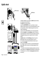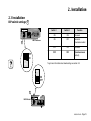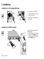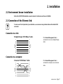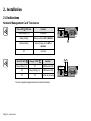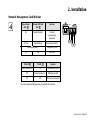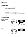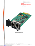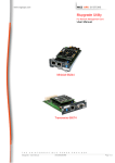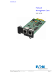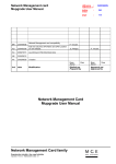
1
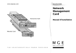
www.mgeups.com
MGE UPS SYSTEMS
Network
Management
Card
Transverse Card
IP=
MAC=00E0D8FF855E
Installation manual
Card Settings
100
10
UPS
data
Reset
1 2
ON
RS232 Download
RS232
ETHERNET
66074
Minislot Card
IP=
MAC=00E0D8FF855D
66244
Card Settings ETHERNET
1 2
ON
Reset
RS232
Download
T H E
UPS data
Power
U N I N T E R R U P T I B L E
10
100
P O W E R
P R O V I D E R
34003641EN/AD
- Page 1
Quick start
ASI
UPS
NMC Transverse
RS232
DATA LINE
PROTECTION
OUT
F
1 II
6
8 II
F II 2
4
F
8 II0 0
D I1
0I 1
E
0
II 1
0
0 I
II
IN
NMC Minislot
I
I
TO BATTERY
CABINET
1 2
ON
Reset
RS232 Download
100
10
ETHERNET
66244
Card Settings ETHERNET
UPS
status
1 2
ON
Reset
RS232
Reset
ETHERNET
100
10
ETHERNET
UPS
status
RS232
Card Settings
66074
Page 2 - 34003641EN/AD
UPS data
Power
10
100
66074
1 2
ON
RS232 Download
IP=
MAC=00E0D8FF855E
ASI
UPS
Card Settings
U-Talk
RS232
Download
Hub
1. Insert and screw the communication card NMC inside the UPS slot.
It is unecessary to shut off the UPS.
2. Configure the network parameters:
◗ If you have a BOOTP/DHCP server on your network, no manual
settings are required. However, ask your network administrator to set the
server parameters so that the IP address assigned to the card is in a
range of fixed addresses.
◗ If you do not have a BOOTP/DHCP server, the network parameters
must be set manually via the Card Settings serial port. Contact your
network administrator to obtain the setting values (sections 3.2 and 3.3).
3. Connect the Ethernet port to the network. Check 10 or 100 LED
flashing.
4. Read IP address via the Card Settings serial port if you have a
BOOTP/DHCP server on your network (sections 3.2 and 3.3).
5. To access the supervision and administration functions via your
browser, enter http://@IP/
6. To access the supervision functions via your Network Management
System (NMS), install, set up and run the selected application on the
NMS station.
7. To access the other advanced configuration parameters, see the user
manual available on the Solution Pac 2 CD-ROM (go to Emb/index.htm)
from GE release or on our Web-site at www.mgeups.com (Download
area section).
Introduction
Thank you for selecting an MGE UPS SYSTEMS product to protect your electrical equipment.
The Network Management Card has been designed with the utmost care. We recommend that you take the time to read
this manual to take full advantage of the many features of your new equipment.
We invite you to discover the entire MGE UPS SYSTEMS range of products and services by visiting our Web site at
www.mgeups.com or by contacting your nearest sales representative.
Environment
MGE UPS SYSTEMS pays great attention to the environmental impact of its products during the design and manufacture
stages, through to the end of its life cycle.
◗ This product complies with the most strict regulations.
◗ It does not contain CFCs or HCFCs.
Recycling of packing materials
Packing materials were selected to facilitate recycling. Please make sure they are correctly recycled in compliance with all
applicable regulations.
Recycling of the product at the end of its life cycle
MGE UPS SYSTEMS undertakes to recycle all recovered products in installations, complying with applicable regulations.
Please contact our sales office.
See the Environment section on our Web site at www.mgeups.com.
Special precautions
◗
◗
If the card must be stored prior to installation, storage must be in a dry place.
The admissible storage temperature range is -10° C to +70° C.
34003641EN/AD
- Page 3
Foreword
EMC compatibility
When correctly installed and used in accordance with the manufacturer’s instructions, Network Management Card comply
with the following standards:
◗ ATI safety: EN 60950/A11 (1998).
◗ EMC: EN 61000-6-2 (1999), EN 61000-6-3 (2002).
Conformity with European directives:
◗ Low voltage: 73/23/EEC and 93/68/EEC.
◗ EMC: 89/336/EEC and 93/68/EEC.
Federal Communication Commission (FCC) statement
This equipment has been tested and found to comply with the limits for a Class A digital device, pursuant to part 15 of the
FCC Rules. These limits are designed to provide reasonable protection against harmful interference when the equipment is
operated in a commercial environment. This equipment generates, uses, and can radiate radio frequency energy and, if not
installed and used in accordance with the instruction manual, may cause harmful interference to radio communications.
Operation of this equipment in a residential area is likely to cause harmful interference in which case the user will be
required to correct the interference at his own expense.
Pictograms used in this manual
Important operations.
Information, advice, help.
Visual indication.
Page 4 - 34003641EN/AD
Action.
Software screen
accessed via the
Network
Management
Card.
UPS Properties : Text in bold italics has
been taken from the software.
Contents
1.
Presentation
1.1
1.2
1.3
1.4
1.5
2.
Unpacking and check on contents ................................................................................................................ 7
Overview ........................................................................................................................................................... 8
Network Management Card Transverse ............................................................................................................. 8
Network Management Card Minislot ................................................................................................................. 9
Functions ........................................................................................................................................................ 10
Technical characteristics ............................................................................................................................... 12
List of parameters and default values .......................................................................................................... 13
Installation
2.1
Installation ....................................................................................................................................................... 15
DIP-switch settings ........................................................................................................................................... 15
Installation in a UPS equipped with slots .......................................................................................................... 16
Installation in a MultiSlot module ...................................................................................................................... 16
2.2
Environment Sensor installation .................................................................................................................. 17
2.3
Connection of the Ethernet link .................................................................................................................... 17
Connection to a hub ......................................................................................................................................... 17
Connection to a computer ................................................................................................................................ 17
Indications ....................................................................................................................................................... 18
Network Management Card Transverse ........................................................................................................... 18
Network Management Card Minislot ................................................................................................................ 19
2.4
34003641EN/AD
- Page 5
Contents
3.
Configuration
3.1
3.2
3.3
3.4
3.5
3.6
4.
5.
Operation
4.1
Operating test following installation and configuration ............................................................................. 26
4.2
Advanced operation ....................................................................................................................................... 26
Maintenance
5.1
5.2
5.3
5.4
6.
Troubleshooting ............................................................................................................................................. 27
Loss of password ........................................................................................................................................... 27
Firmware upgrade .......................................................................................................................................... 28
Troubleshooting ............................................................................................................................................. 28
For Network Management Card Minislot .......................................................................................................... 28
For Network Management Card Transverse .................................................................................................... 28
Appendix
6.1
Page 6 - 34003641EN/AD
Default IP address .......................................................................................................................................... 20
Parameter setting ........................................................................................................................................... 20
Via the serial link .............................................................................................................................................. 20
Via the network ................................................................................................................................................. 21
Setting the network parameters .................................................................................................................... 21
Restarting the card ......................................................................................................................................... 23
Restoring the default parameters ................................................................................................................. 24
Restoring the default password .................................................................................................................... 25
Glossary .......................................................................................................................................................... 29
1. Presentation
1.1 Unpacking and check on contents
Solution-Pac
Network Management Card
Transverse:
The indispensable
companion
sofware
for your UPS
Network
Management
Card
L'indispensable
complément
logiciel
de votre onduleur
Installation manual
Transverse card
0D
I
Card Settings
10
UPS
status
Reset
61F
IIII
F8II
42
8FII
I
100
II 101
00E
III
100
1 2
ON
I
Minislot card
I
RS232 Download
RS232
ETHERNET
66073
66244
Card Settings ETHERNET
1 2
ON
Reset
RS232
Download
UPS data
Power
10
A front plate specially designed for
Galaxy PW UPSs.
MGE
100
◗
UPS SYSTEMS
IP=
MAC=00E0D8FF855E
IP=
MAC=00E0D8FF855E
100
10
Reset
A serial communication cable used for
configuration and maintenance.
◗
Card Settings
100
10
UPS
data
Reset
RS232
ETHERNET
RS232 Download
66074
◗
Installation and user manual.
◗
The Solution-Pac 2 CD-ROM.
Card Settings
UPS
data
1 2
ON
RS232 Download
RS232
ETHERNET
66074
Network Management Card
Minislot:
Network
Management
Card
Installation manual
An NMC Minislot communication card,
with a standard front plate already installed.
◗
Transverse card
0D
I
100
I
I
Minislot card
10
UPS
data
Reset
61F
IIII
F8II
42
8FII
I
100
II 101
00E
III
Card Settings
1 2
ON
RS232 Download
RS232
ETHERNET
66073
66244
Card Settings ETHERNET
1 2
ON
Reset
RS232
Download
UPS data
Power
10
MGE
100
UPS SYSTEMS
A serial communication cable used for
configuration and maintenance.
◗
◗
Installation and user manual.
F
1 II
6
8 II
F II 2
4
F
8 II0 0
D I1
0I 1
0
E
0 II 1
0 I
II
I
I
NMC
Minislot
66244
IP=
MAC=00E0D8FF855E Card Settings ETHERNET
1 2
ON
NMC
Transverse
An NMC Transverse communication card,
with a standard front plate already installed.
◗
Reset
RS232
Download
UPS data
Power
10
100
34003641EN/AD
- Page 7
1. Presentation
1.2 Overview
Network Management Card Transverse
2
4
Labels for Ethernet and IP addresses.
7
DIP switches for configuration
(RS232 Download).
8
Reset button.
2
Green 100 M Ethernet LED (100).
3
Orange 10 M Ethernet LED (10).
6
UPS Data LED signalling data transfers
(UPS Data).
4
1
3
IP=
MAC=00E0D8FF855E
Card Settings
100
10
Reset
UPS
data
1 2
ON
RS232 Download
ETHERNET
RS232
5
RS232 serial port for Environment Sensor,
configuration and maintenance (Card
settings / RS232).
9
Card part number.
1
10/100BT Ethernet port (ETHERNET).
66074
10
Jumper for return to the default password.
The address label 4 is made up of two areas:
◗ The upper line may be used to manually note the IP address assigned to the card.
◗ The lower line indicates the card Ethernet address (MAC address).
Page 8 - 34003641EN/AD
1. Presentation
Network Management Card Minislot
Labels for Ethernet and IP addresses.
7
DIP-switches for configuration
(RS232 Download).
8
Reset button.
5
RS232 serial port for Environment Sensor,
configuration and maintenance (Card
settings / RS232).
F
1 II
6 I
8 I
F II 2
FI 4
8 I 00
D I1
0I 1
EI 0
I 1
0
0 II
I
4
I
I
8
7
6
5
3
1
IP=
MAC=00E0D8FF855E
66244
Card Settings ETHERNET
1 2
ON
Reset
RS232
Download
UPS data
Power
10
9
Card part number.
1
10/100BT Ethernet port (ETHERNET).
2
Green 100 M Ethernet LED (100).
3
Orange 10 M Ethernet LED (10).
11
Card power LED (Power).
100
6
UPS Data LED signalling data transfers or
use of the serial link (UPS Data).
10
Jumper for return to the default password.
The address label 4 is made up of two areas:
◗ The upper area may be used to manually note the IP address assigned to the card.
◗ The lower area indicates the card Ethernet address (MAC address).
34003641EN/AD
- Page 9
1. Presentation
1.3 Functions
UPS supervision
UPS
SNMP
IP=
MAC=00E0D8FF855E
1 2
ON
Reset
RS232 Download
NMC
Transverse
HTTP
100
UPS administration
10
ETHERNET
ETHERNET
UPS
data
SNMP
Card Settings
RS232
HTTP
66074
Servers protection
HTTP/SNMP
NMC
Minislot
66244
TELNET
Card Settings ETHERNET
Network
Shutdown
Module
Card configuration
1 2
ON
Reset
IP= RS232
MAC=00E0D8FF855E
Download
UPS data
Power
10
100
RS232
RS232
DATA LINE
IN
PROTECTION
HTTP
OUT
TO BATTERY
CABINET
Card maintenance
RS232
Environment Sensor
Page 10 - 34003641EN/AD
TFTP
RS232
1. Presentation
The Network Management Card is used to directly connect the UPS to a computer network, while simultaneously
operating as a Web server and SNMP agent.
Remote connections are made using an ordinary internet browser or an NMS station.
All the functions offered by the Network Management Card are accessible via a number of MGE UPS SYSTEMS software
applications, depending on the user’s needs.
Functions
Mupgrade or
Web
Console
Download browser Direct Telnet
Supervision
UPS properties
UPS log
Event log
Alarm subscription
Direct email notification
Environement parameters
yes
yes
yes
yes
yes
yes
Configuration - Administration
Network parameters
Community name
Shutdown parameters
Scheduled shutdown
Management table
Time
yes
yes
yes
yes
yes
yes
yes
yes
yes
yes
yes
yes
yes
yes
yes
yes
Maintenance
Network cards discovery
Firmware upgrade
Reset agent
Factory reset
Servers/Workstations protection
Network
Supervision
EPM Managt-Pac Shutdown Module
yes
yes
yes
yes
yes
yes
yes
yes
yes
yes
yes
yes
yes
yes (Mupgrade)
yes
yes
34003641EN/AD
- Page 11
1. Presentation
1.4 Technical characteristics
Characteristics
Functions
Supervision
Simultaneous connection of up to 15 browsers.
Up to 500 events stored in memory with battery backup.
◗ Automatic refresh of the Properties page.
◗
◗
Alarms
◗
Alarm notification via Browser (applet), email and SNMP (trap).
Protection of client stations
◗
Up to 50 protected stations.
Network
◗
Fast ETHERNET 10/100 Mbits, auto-negotiation.
HTTP 1.1, SNMP V1, TELNET, TFTP, NTP, BOOTP, DHCP.
◗ Simultaneous management of protocols.
◗
Browsers
◗
◗
International
◗
◗
NMS
◗
◗
MIB
Microsoft Internet Explorer 5.x or higher.
Netscape Navigator 6.x or higher.
Web pages in English, French, German, Italian and Spanish.
Automatic detection of browser language.
Enterprise Power Manager (EPM).
Management-Pac 2.
Standard MIB II.
MGE V1.6 MIB.
◗ IETF MIB.
◗
◗
Configuration
◗
◗
Downloads
◗
◗
Page 12 - 34003641EN/AD
Access via a password.
Setting of parameters: IP, System, Date/time, Community name, etc.
Single card or Multicard via the network using Mupgrade.
Single card via TFTP or an RS232 serial link.
1. Presentation
1.5 List of parameters and default values
Functions
Network
System
Parameters
Default values
Possible values
◗ IP Address
◗ 172.17.xx.yy (see section 3.1)
◗ Network IP address
◗ Subnet Mask
◗ 255.255.0.0
◗ Network IP address
◗ Gateway Address
◗ 0.0.0.0
◗ Network IP address
◗ Host
◗ UPS xxxx
◗ Host name
◗ Domain name
◗ ups.domain.com
◗ Domain name
◗ Telnet Connection
◗ Enable
◗ Enable/Disable
◗ BOOTP/DHCP
◗ Enable
◗ Enable/Disable
◗ Network Upgrade
◗ Enable
◗ Enable/Disable
◗ Primary DNS Server
◗ 0.0.0.0
◗ Network IP address
◗ Secondary DNS Server
◗ 0.0.0.0
◗ Network IP address
◗ SMTP Server
◗ smtpserver.domain.com
◗ IP address or DNS name
◗ NTP Server
◗ 0.0.0.0
◗ Network IP address
◗ UPS Contact
◗ Computer Room Manager
◗ 32 characters max.
◗ UPS Location
◗ Computer Room
◗ 32 characters max.
◗ History Log Interval (sec)
◗ 60
◗ 20 to 99999
◗ Refresh Rate (sec)
◗ 10
◗ 5 to 99999
◗ Default Language
◗ Auto
◗ Auto/English/French/
◗ Outputs name
◗ Master/Group1/Group2
◗ System stop duration (sec)
◗ 120
◗ Working time on battery (min)
◗ 30
German/Italian/Spanish
◗ 30 characters max.
◗ 0 to 9999
◗ 0 to 1092
◗ (Empty list)
◗ 50 max.
before stop
Manager table
Remarks. Same password must be used to modify those parameters via internet browser, serial link or Telnet.
34003641EN/AD
- Page 13
1. Presentation
Parameters
Functions
Access control
Email notification
Default values
Possible values
◗ Manager Login
◗ MGEUPS
◗ 10 characters max.
◗ Password
◗ MGEUPS
◗ 10 characters max.
◗ Current community read-only
◗ public
◗ 31 characters max.
◗ Current community read/write
◗ public
◗ 31 characters max.
◗ Trap Port Number
◗ 162
◗ (free)
◗ Recipients
◗ [email protected]
◗ 4 recipients max.
◗ Logs attached files
◗ None
◗ Measures / Events /
◗ Sender
◗ [email protected]
◗ Subject
◗ MGE UPS SYSTEMS
◗ Text
◗ None
◗ Evenement table
◗ UPS fault / UPS Off sequence
System / Environment logs
◗ 60 characters max.
◗ see configuration page
◗ 136 characters max.
◗ see configuration page
in progress
Environment
Time
Serial link
◗ Temperature unit
◗ Celsius
◗ Celsius / Fahrenheit
◗ Temperature threshold
◗ 40°C max. / 5°C min.
◗ 0 to 70°C
◗ Humidity threshold
◗ 90% max. / 5% min.
◗ 0 to 100%
◗ Setting time
◗ Set manually
◗ NTP Server / Computer
◗ Time zone
◗ GMT-05 Eastern Time
◗ (see list)
◗ Daylight Saving Time
◗ OFF
◗ ON / OFF
◗ Speed
◗ 9600 bauds
◗ (not authorized)
◗ Data bits
◗8
◗ (not authorized)
◗ Stop bit
◗1
◗ (not authorized)
◗ Parity
◗ None
◗ (not authorized)
Remarks. Same password must be used to modify those parameters via internet browser, serial link or Telnet.
Page 14 - 34003641EN/AD
2. Installation
2.1 Installation
DIP-switch settings 7
IP=
MAC=00E0D8FF855E
Switch 1
Card Settings
100
10
Reset
UPS
data
1 2
ON
RS232 Download
RS232
ETHERNET
Function
ON
ON
Reserved
ON
OFF
Serial link
downloads enabled
OFF
ON
Reserved
OFF
OFF
Operational mode
(default)
66074
NMCTransverse
7
Switch 2
OFF
ON
1 2
ON
To get more information about downloading, see section 5.3.
1 2
ON
ON
OFF
7
IP=
MAC=00E0D8FF855E
66244
Card Settings ETHERNET
1 2
ON
NMC Minislot
Reset
RS232
Download
UPS data
Power
10
100
34003641EN/AD
- Page 15
2. Installation
Installation in a UPS equipped with slots
It is not necessary to turn the UPS off.
ASI
UPS
DATA LINE
PROTECTION
F
1 II
6
8 II
F II 2
4
F
8 II0 0
D I1
0I 1
E
0
II 1
IN
OUT
I
TO BATTERY
CABINET
I
1 2
ON
Reset
100
ETHERNET
10
UPS
data
RS232
Card Settings
NMC
Minislot
66244
Card Settings ETHERNET
1 2
ON
RS232 Download
Reset
RS232
Download
UPS data
Power
10
100
2 - Insert and secure the communication
card in the UPS.
66074
U-Talk
1 - Using a screwdriver, remove the cover
from a free slot in the UPS.
RS232
0
0 I
II
NMC
Transverse
Installation in a MultiSlot module
MultiSlot
ASI
UPS
U-Talk
NMC
Transverse
IP=
MAC=00E0D8FF855E
This installation is possible only with the
NMC Transverse.
1 - Using a screwdriver, remove the cover
from a free slot in the MultiSlot module.
2 - Insert and secure the communication
card in the MultiSlot module.
Card Settings
100
10
Reset
UPS
data
1 2
ON
RS232 Download
ETHERNET
RS232
66074
Us/Out/Ausg
Page 16 - 34003641EN/AD
2. Installation
2.2 Environment Sensor installation
Refer to the 34003783EN installation manual included in the Environment Sensor kit (66846).
2.3 Connection of the Ethernet link
To make use of the full potential of your installation, we recommend using shielded cables with shielded RJ45
connectors.
Connection to a hub
1
2
3
4
5
6
7
8
1
2
3
4
5
6
7
8
If the Network Management Card is
connected to a hub, use a straight-through
cable.
RJ45
RJ45
Straight-through 10/100 Base-T cable
Connection to a computer
1
2
3
4
5
6
7
8
1
2
3
4
5
6
7
8
If the Network Management Card is
connected to a computer, use a crossover
cable.
RJ45
RJ45
Crossover 10/100 Base-T cable
34003641EN/AD
- Page 17
2. Installation
2.4 Indications
Network Management Card Transverse
Green LED 6 UPS Data
Function
IP=
MAC=00E0D8FF855E
Card Settings
100
10
Reset
Slowly flashing (1 s)
Start phase
Rapidly flashing
Dialogue with the UPS or MultiSlot
Random flashing
Data exchange with the UPS or
MultiSlot
Off
Card fault
UPS
Data
1 2
ON
RS232 Download
RS232
ETHERNET
66074
6
Green 100 LED 2
Orange 10 LED 3
Function
Slowly flashing (1 s)
Off
100M Ethernet traffic
Off
Slowly flashing (1 s)
10M Ethernet traffic
Off
Off
Ethernet not connected
2 3
IP=
MAC=00E0D8FF855E
Card Settings
100
The card is operational approximately 30 seconds after insertion.
Page 18 - 34003641EN/AD
10
Reset
UPS
Data
1 2
ON
RS232 Download
ETHERNET
RS232
66074
2. Installation
Network Management Card Minislot
Green Power
LED 11
Orange UPS Data
LED 6
Function
On
Random flashing
Terminal
communication
operational
Off / On
Rapid flashing
Download via RS232
66244
Card Settings ETHERNET
1 2
ON
Reset
RS232
Download
UPS data
Power
10
100
6 11
3
2
Diagnostics mode
Flashing alternately
On
IP=
MAC=00E0D8FF855E
Card fault
On
100 LED 2
10 LED 3
Function
Slowly flashing (1 s)
Off
100M Ethernet traffic
Off
Slowly flashing (1 s)
10M Ethernet traffic
Off
Off
Ethernet not connected
The card is operational approximately 30 seconds after insertion.
34003641EN/AD
- Page 19
3. Configuration
3.1 Default IP address
The Network Management Card comes with a default IP address. This address is derived from the MAC address on the
label on the front of the card.
The format of the MAC address is 00 E0 D8 LL MM NN, where:
◗ 00 E0 D8 is the manufacturer code in hexadecimal format,
◗ LL MM NN is the serial number of the card in hexadecimal format.
The default IP address of the card is made up of four bytes of which the last two are derived from the MAC address.
The format of the IP address is 172.17.xxx.yyy, where:
◗ 172.17 is a fixed value,
◗ xxx is the decimal value of the MM byte,
◗ yyy is the decimal value of the NN byte.
For example, for a MAC address 00 E0 D8 04 0A 15, the corresponding default IP address is 172.17.10.21.
3.2 Parameter settings
Via the serial link
Run Hyper Terminal on a PC running Windows (9x, Me, NT4.0, 2000 or
higher).
◗ Connect the card to the PC using the cable supplied.
◗ Set up the terminal with the following communication parameters:
◗ 9600 bauds.
◗ 8 data bits.
◗ 1 stop bit.
◗ no parity.
◗ no flow control.
◗ ASCII: "echo typed characters locally" option disabled.
◗ Press the Carriage return key. The configuration menu is displayed.
◗ Enter the password (MGEUPS by default).
◗ The main menu is displayed.
◗ Select one of the items in the configuration menu.
◗
Page 20 - 34003641EN/AD
3. Configuration
Via the network
Via Telnet
Check that the card is connected to the ETHERNET network.
Launch the "Run" command under Windows on a PC.
◗ Enter telnet @IP
◗ Connection is made. A screen is displayed.
◗ Enter the password (MGEUPS by default).
◗ The main menu is displayed.
◗ Select one of the items in the configuration menu.
◗
◗
Via a browser
Check that the card is connected to the ETHERNET network.
Run the browser on a PC.
◗ Enter the URL http://@IP/
◗ The main page is displayed.
◗ Select one of the items in the settings menu.
◗
◗
3.3 Setting the network parameters
The Network Management Card requires the following network parameters:
◗ The IP address used for identification on the network.
◗ The Subnet mask which defines the group of users to which it is connected.
◗ The address of the Gateway to which it connects to communicate with another subnet.
The network parameters are set up each time the system is started:
◗ Automatically if the network is equipped with a BOOTP or DHCP server;
◗ With the fixed parameters set manually if an IP address server is not available.
If the BOOTP/DHCP server is not ready, saved parameters are used.
34003641EN/AD
- Page 21
3. Configuration
The table below presents the initialisation mode for the network parameters:
Network configuration
BOOTP/DHCP server
installed
No server available
Mode sélectionné
◗ BOOTP/DHCP enabled
Fonctionnement
◗ Reception and use of the network parameters sent by the
server (10s max.).
◗ BOOTP/DHCP disabled
◗ Use of manual settings.
◗ BOOTP/DHCP enabled
◗ Attempt to connect to a BOOTP/DHCP server for ten seconds,
then use settings saved during previous connection or default IP
address.
◗ BOOTP/DHCP disabled
◗ Use of manual settings.
Important. As long as the card is not connected to the network, it continuously attempts to make connection.
Once the connection has been established, the operational mode presented in the table above becomes effective.
Via the serial link or Telnet
Select the "Agent configuration" command by entering 1.
Select the item numbers and modify all the IP parameters (address, mask, gateway).
◗ Once all the modifications have been made, exit following the instructions on the screen.
◗
◗
Via a browser
Select the "IP network" command in the configuration menu.
Modify all the IP parameters (address, mask, gateway).
◗ Click the "Save changes" button.
◗ Enter the user name (MGEUPS by default) and the password (MGEUPS by default).
◗
◗
Important. The modifications of the network parameters are taken into account when the card is restarted.
Page 22 - 34003641EN/AD
3. Configuration
3.4 Restarting the card
Manually
◗
Press the Reset 8 button.
Via the serial link or Telnet
◗
◗
Select the "Restart agent" command by entering 6.
Then follow the instructions on the screen.
Via a browser
Select the "System" command in the configuration menu.
Click the "Reset communication" button.
◗ Enter the user name (MGEUPS by default) and the password (MGEUPS by default).
◗
◗
Remarks:
◗ The card is operational approximately 30 seconds after it is started.
◗ User customized parameters are not modified after a restart.
◗ Pressing the Reset 8 button does not modify any parameters.
34003641EN/AD
- Page 23
3. Configuration
3.5 Restoring the default parameters
If problems occur during the configuration procedure or if the password is lost, it is possible to return to the
default parameters (factory settings), listed in section 1.5.
Via Telnet or Hyper Terminal
Select the "Agent configuration" command by entering 1.
Select the "Reset configuration to default" command by entering 5.
◗ Then follow the instructions on the screen.
◗
◗
Via a browser
Select the "System" command in the configuration menu.
Click the "Factory Reset" button. The IP parameters are kept if the option is selected.
◗ Enter the user name (MGEUPS by default) and the password (MGEUPS by default) if necessary.
◗
◗
Remark. Date and time are not modified after restoring default parameters.
Page 24 - 34003641EN/AD
3. Configuration
3.6 Restoring the default password
If you loose your password, to restore the default one MGEUPS, you must perform following steps:
◗ Pull out the card from the UPS slot.
◗ Move jumper as shown below.
◗ Insert the card inside the UPS slot and wait for 30 seconds.
◗ Pull out the card from the UPS slot again.
◗ Move jumper to the original position shown below.
◗ Insert the card inside the UPS slot, secure it, and wait for 30 seconds
◗ Password is now reset to MGEUPS. You can customise it again.
NMC Transverse
JP1
Original
position
1
3
2
4
1
3
2
4
1
3
5
7
2 Original
4 position
6
8
1
3
5
7
2
4
6
8
Remark. When the jumper is not returned
to its original position, MGEUPS
password is restored every time the card
is restarted.
NMC Minislot
JP1
34003641EN/AD
- Page 25
4. Operation
4.1 Operating test following installation and configuration
Launch the "Run" command in Windows on a station connected to the same subnet.
Enter ping @IP (example: ping 172.17.10.21).
If no answer is sent by the card, check the network parameters.
◗ Use the browser to go to the URL address http://@IP/ and check the page for the "UPS Properties".
◗
◗
4.2 Advanced operation
To discover all the advanced functions offered by the Network Management Card, see the user documentation on the
Solution-Pac 2 CD-ROM or on the www.mgeups.com site.
Page 26 - 34003641EN/AD
5. Maintenance
5.1 Troubleshooting
Problem
All the LEDs are off.
Cause
Solution
The card is not supplied
with power.
◗
The "10" or "100" LED
remains off following
connection of the cable.
The Ethernet link is not
running.
◗
The "UPS data" LED is off.
The card has faulted.
◗
Connection using the
browser is not possible.
The network
parameters are
incorrect.
◗
The configuration menu
does not work.
◗ The RS232 serial link
is not operational.
◗ The IP address
entered by the user is
incorrect.
◗
Check that the UPS is on.
Check that the card is correctly inserted and secured in its slot.
◗ Remove the card and insert it again.
◗
Check the cable.
If connection is made using a hub, check that the hub is
supplied with power.
◗
Contact the after-sales technical support.
Check that the "10" or "100" LED is on.
Check that the URL corresponds to the current address of the
card.
◗ Check that the computer can access the address (check the
"Subnet-mask" and the "Default gateway" for the computer)
◗ Check the position of the jumper.
◗ Use the "Ping" command to test the connection.
◗
Make sure the cable used is that supplied with the card.
Check the terminal parameters.
◗ Test the link using the default parameters.
◗
Note: if the problem cannot be solved, contact the after-sales technical support at the address indicated on the
www.mgeups.com site.
5.2 Loss of password
To return to the default password, see section 3.6.
34003641EN/AD
- Page 27
5. Maintenance
5.3 Firmware upgrade
The Network Management Card firmware can be upgraded easily through two different download procedures:
◗ Via ETHERNET with Mupgrade software tool (Windows only).
◗ Via ETHERNET with tftp command (Unix and Windows).
◗ Via serial link with Download software tool.
Both software tools Mupgrade and Download are available on the Solution-Pac 2 CD-ROM or on www.mgeups.com.
MGE UPS SYSTEMS Web site is periodically upgraded with new firmware releases.
To get more information about those software tools, refer to the NMC user manual on the Solution-Pac 2 CD-ROM or on
www.mgeups.com.
5.4 Loss of serial cable
For Network Management
Card Minislot
DB9/RJ45 cable (1,8 m max)
female DB9
connector
For Network Management
Card Transverse
shielded
cable
3
6
4
frame
male RJ45
connector
DB9/DB9 cable (1,8 m max)
2
3
5
frame
male DB9
connector
Page 28 - 34003641EN/AD
male RJ45
connector
2
3
5
frame
female DB9
connector
female DB9
connector
male DB9
connector
2
3
5
frame
shielded
cable
female DB9
connector
6. Appendix
6.1 Glossary
BOOTP
Bootstrap Protocol. A protocol for restart of products connected to the network.
DHCP
Dynamic Host Configuration Protocol. A protocol for the dynamic assignment of network parameters.
DST
Daylight Saving Time.
Ethernet
Technology used in local networks.
EPM
Enterprise Power Manager.
HTTP
HyperText Transfer Protocol. A protocol based on TCP (port 80) used to transfer requests and data
between a server and a browser.
Internet
Network established worldwide for interconnections between computers, based on the TCP/IP
protocol.
Intranet
Local network offering the same services as the internet.
IP address
Logic address of an element connected to a network. It is a unique address in the given network.
MAC address
Physical address assigned to a card. It is unique for each card.
MultiSlot
An expansion module for communication cards.
NMC
Network Management Card.
NMS
Network Management System.
NSM
Network Shutdown Module.
NTP
Network Time Protocol.
SNMP
System Network Management Protocol.
UPS
Uninterruptible Power System.
URL
Uniform Resource Locator: the unique address for a page on the internet.
34003641EN/AD
- Page 29
Page 30 - 34003641EN/AD