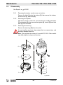
1
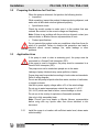
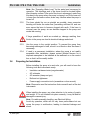
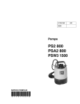
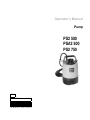
Operator’s Manual Pump PS2 500 PSA2 500 PS2 750 EN 5000187791 5 0 0 0 04 1 8 1211 7 7 9 1 Copyright notice © Copyright 2011 by Wacker Neuson Production Americas LLC All rights, including copying and distribution rights, are reserved. This publication may be photocopied by the original purchaser of the machine. Any other type of reproduction is prohibited without express written permission from Wacker Neuson Production Americas LLC. Any type of reproduction or distribution not authorized by Wacker Neuson Production Americas LLC represents an infringement of valid copyrights. Violators will be prosecuted. Trademarks All trademarks referenced in this manual are the property of their respective owners. Manufacturer Wacker Neuson Production Americas LLC N92W15000 Anthony Avenue Menomonee Falls, WI 53051 U.S.A. Tel: (262) 255-0500 · Fax: (262) 255-0550 · Tel: (800) 770-0957 www.wackerneuson.com Original instructions This Operator’s Manual presents the original instructions. The original language of this Operator’s Manual is American English. PS 2 500 / PS 2 750 / PSA 2 500 Foreword Foreword SAVE THESE INSTRUCTIONS—This manual contains important instructions for the machine models below. These instructions have been written expressly by Wacker Neuson Production Americas LLC and must be followed during installation, operation, and maintenance of the machines. Machines covered in this manual Machine documentation Expectations for information in this manual Machine Item Number PS2 500 0009113 0009172 PSA2 500 0009114 PS2 750 0009115 0009116 From this point forward in this documentation, Wacker Neuson Production Americas LLC will be referred to as Wacker Neuson. Keep a copy of the Operator’s Manual with the machine at all times. Use the separate Parts Book supplied with the machine to order replacement parts. Refer to the separate Repair Manual for detailed instructions on servicing and repairing the machine. If you are missing any of these documents, please contact Wacker Neuson to order a replacement or visit www.wackerneuson.com. When ordering parts or requesting service information, be prepared to provide the machine model number, item number, revision number, and serial number. This manual provides information and procedures to safely operate and maintain the above Wacker Neuson model(s). For your own safety and to reduce the risk of injury, carefully read, understand, and observe all instructions described in this manual. Wacker Neuson expressly reserves the right to make technical modifications, even without notice, which improve the performance or safety standards of its machines. The information contained in this manual is based on machines manufactured up until the time of publication. Wacker Neuson reserves the right to change any portion of this information without notice. Manufacturer’s This manual contains references to approved parts, attachments, and approval modifications. The following definitions apply: Approved parts or attachments are those either manufactured or provided by Wacker Neuson. Approved modifications are those performed by an authorized Wacker Neuson service center according to written instructions published by Wacker Neuson. wc_tx002037gb.fm 3 Foreword PS 2 500 / PS 2 750 / PSA 2 500 Unapproved parts, attachments, and modifications are those that do not meet the approved criteria. Unapproved parts, attachments, or modifications may have the following consequences: Serious injury hazards to the operator and persons in the work area Permanent damage to the machine which will not be covered under warranty Contact your Wacker Neuson dealer immediately if you have questions about approved or unapproved parts, attachments, or modifications. 4 wc_tx002037gb.fm PS 2 500 / PS 2 750 1 Table of Contents Foreword 3 Safety Information 7 1.1 1.2 1.3 1.4 1.5 Signal Words Used in this Manual ....................................................... 7 Machine Description and Intended Use ............................................... 8 Operating and Electrical Safety ............................................................ 9 Service Safety .................................................................................... 10 Labels ................................................................................................. 11 2 Lifting and Transporting 12 3 Installation 13 3.1 3.2 3.3 3.4 3.5 3.6 3.7 3.8 4 Operation 4.1 4.2 4.3 4.4 4.5 5 Components ....................................................................................... 13 Preparing the Machine for First Use ................................................... 14 Application Area ................................................................................. 14 Preparing for Installation .................................................................... 15 Checks to Make Before Installation .................................................... 17 Electrical Wiring .................................................................................. 18 Connecting the Power Supply ............................................................ 19 Cable Assembly ................................................................................. 20 21 Before Starting ................................................................................... 21 Operating Water Level ..................................................................... 23 Motor Protection System (Motor Protector) ........................................ 24 Operating Cycle of Automatic Type ................................................ 24 Emergency Shutdown Procedure ....................................................... 25 Maintenance 5.1 5.2 5.3 5.4 5.5 5.6 5.7 26 Periodic Maintenance Schedule ......................................................... 26 Storage ............................................................................................... 27 Replacement Parts ............................................................................. 28 Disassembly and Reassembly ........................................................... 29 Disassembly ....................................................................................... 30 Reassembly ........................................................................................ 31 Troubleshooting .................................................................................. 32 wc_bo5000187791_04TOC.fm 5 Table of Contents 6 PS 2 500 / PS 2 750 Technical Data 6.1 6.2 6.3 33 Standard Specifications .......................................................................33 Operating Specifications ....................................................................34 Dimensions ..........................................................................................34 7 Schematics 35 8 AEM Safety Manual 39 6 wc_bo5000187791_04TOC.fm PS 2 500 / PS 2 750 / PSA 2 500 1 1.1 Safety Information Safety Information Signal Words Used in this Manual This manual contains DANGER, WARNING, CAUTION, NOTICE, and NOTE signal words which must be followed to reduce the possibility of personal injury, damage to the equipment, or improper service. This is the safety alert symbol. It is used to alert you to potential personal hazards. f Obey all safety messages that follow this symbol. DANGER DANGER indicates a hazardous situation which, if not avoided, will result in death or serious injury. f To avoid death or serious injury from this type of hazard, obey all safety messages that follow this signal word. WARNING WARNING indicates a hazardous situation which, if not avoided, could result in death or serious injury. f To avoid possible death or serious injury from this type of hazard, obey all safety messages that follow this signal word. CAUTION CAUTION indicates a hazardous situation which, if not avoided, could result in minor or moderate injury. f To avoid possible minor or moderate injury from this type of hazard, obey all safety messages that follow this signal word. NOTICE: Used without the safety alert symbol, NOTICE indicates a situation which, if not avoided, could result in property damage. Note: A Note contains additional information important to a procedure. wc_si000035gb.fm 7 Safety Information 1.2 PS 2 500 / PS 2 750 / PSA 2 500 Machine Description and Intended Use This machine is a submersible water pump. The Wacker Neuson Submersible Pump consists of an electric motor, an impeller, a strainer, and a metal casing with ports for water suction and discharge. Power is supplied to the pump through a corded plug or a hard-wired connection, depending on the installation. The operator connects hoses to the pump and routes them so that water is pumped from the work area and discharged into an appropriate location. This machine is intended to be used for general de-watering applications. This machine is intended for the pumping of clear water, or water containing solids up to the size stated within the products specifications, and up to the flow, head, and suction lift limits also stated within the product specifications. This machine has been designed and built strictly for the intended use described above. Using the machine for any other purpose could permanently damage the machine or seriously injure the operator or other persons in the area. Machine damage caused by misuse is not covered under warranty. The following are some examples of misuse: • Pumping flammable, explosive, or corrosive fluids • Pumping hot or volatile fluids that result in pump cavitation • Operating the pump outside of product specifications due to incorrect diameter hoses, incorrect length hoses, other inlet or outlet restrictions, or excessive suction lift or head • Using the machine as a ladder, support, or work surface • Using the machine to carry or transport passengers or equipment • Operating the machine outside of factory specifications • Operating the machine in a manner inconsistent with all warnings found on the machine and in the Operator’s Manual. This machine has been designed and built in accordance with the latest global safety standards. It has been carefully engineered to eliminate hazards as far as practicable and to increase operator safety through protective guards and labeling. However, some risks may remain even after protective measures have been taken. They are called residual risks. On this machine, they may include exposure to: • Electric shock from improper electrical connections or high voltage • Personal injury from improper lifting techniques • Projectile hazard from discharge 8 wc_si000035gb.fm PS 2 500 / PS 2 750 / PSA 2 500 Safety Information To protect yourself and others, make sure you thoroughly read and understand the safety information presented in this manual before operating the machine. Operator qualifications Only trained personnel are permitted to start, operate, and shut down the machine. They also must meet the following qualifications: • have received instruction on how to properly use the machine • are familiar with required safety devices The machine must not be accessed or operated by: • children • people impaired by alcohol or drugs Personal Protective Equipment (PPE) Wear the following Personal Protective Equipment (PPE) while operating this machine: • Close-fitting work clothes that do not hinder movement • Safety glasses with side shields • Hearing protection • Safety-toed footwear Replacement parts When replacement parts are required for this machine, use only Wacker Neuson replacement parts or those parts equivalent to the original in all types of specifications, such as physical dimensions, type, strength, and material. 1.3 Operating and Electrical Safety WARNING wc_si000035gb.fm To reduce risk of electric shock, connect only to a properly grounded, grounding-type receptacle. Risk of electric shock—this pump has not been investigated for use in swimming pool areas. An acceptable motor-control switch shall be provided at the time of installation according to local codes and regulations. To reduce risk of electric shock, follow instructions in this manual for proper installation. CAUTION: This pump may automatically restart. Prior to working on the pump or control panel, all supply circuits must be disconnected. CAUTION: Risk of shock—do not remove cord and strain relief. 9 Safety Information 1.4 PS 2 500 / PS 2 750 / PSA 2 500 Service Safety Service training Before servicing or maintaining the machine: • Read and understand the instructions contained in all manuals delivered with the machine. • Familiarize yourself with the location and proper use of all controls and safety devices. • Only trained personnel shall troubleshoot or repair problems occurring with the machine. • Contact Wacker Neuson for additional training if necessary. When servicing or maintaining this machine: • Do not allow improperly trained people to service or maintain the machine. Personnel servicing or maintaining the machine must be familiar with the associated potential risks and hazards. Personal Protective Equipment (PPE) Wear the following Personal Protective Equipment (PPE) while servicing or maintaining this machine: • Close-fitting work clothes that do not hinder movement • Safety glasses with side shields • Hearing protection • Safety-toed footwear In addition, before servicing or maintaining the machine: • Tie back long hair. • Remove all jewelry (including rings). Replacing parts and labels • Replace worn or damaged components. • Replace all missing and hard-to-read labels. • When replacing electrical components, use components that are identical in rating and performance as the original components. • When replacement parts are required for this machine, use only Wacker Neuson replacement parts or those parts equivalent to the original in all types of specifications, such as physical dimensions, type, strength, and material. 10 wc_si000035gb.fm PS 2 500 / PS 2 750 / PSA 2 500 1.5 Safety Information Labels Wacker Neuson Corporation Menomonee Falls, WI 53051 USA Model Item No. Man.Y/M Serial No. V Hz Max.m Phase Max.L/min kg Rev. THERMALLY PROTECTED INDOORS OR OUTDOORS CSA ENCLOSURE 3 Amp. Conforms to UL Std. 778 Cert. to CAN/CSA St d. C22.2 No.108-M89 kW R Max. ft Max.GPM lbs HP C L I STED 2001993 A nameplate listing the model number, item number, revision number, and serial number is attached to each unit. Please record the information found on this nameplate so it will be available should the nameplate become lost or damaged. When ordering parts or requesting service information, you will always be asked to specify the model number, item number, revision number, and serial number of the unit. US MADE IN TAIWAN CAUTION Do not attempt to operate this product before reading the Operator’s Manual and understanding its contents. Mishandling of this product may result in explosion, fire, or electrical shock. Do not pull on the power cord or use the power cord to lift the pump. Always use a dedicated ground leakage circuit breaker. Be sure to install the ground wire securely. Be sure to disconnect the power supply before handling or inspecting the pump. Never insert your hand into the pump inlet holes while the pump is connected to the power supply. wc_si000035gb.fm 11 Lifting and Transporting 2 PS 2 500 / PS 2 750 / PSA 2 500 Lifting and Transporting WARNING Do not under any circumstances install or move the pump by suspending it from the cable assembly. The cable may be damaged, causing electrical leakage, shock, or fire. When installing the pump, pay close attention to its center of gravity and weight. If it is not lowered into place correctly, it may fall and be damaged or cause injury. CAUTION When transporting the pump by hand, be sure to employ manpower commensurate with the weight of the pump. To avoid back injury when lifting the pump, bend the knees to pick it up rather than bending your back only. Avoid dropping the pump or other strong impact. Lift the pump by holding it firmly with the hands or by attaching a rope or chain to the handle. CAUTION Model PSA2 500—Do not lift or hang the pump by the level relay unit (1). It will lead to damage and may cause leakage, electric shock, and fire See Graphic: wc_gr000259 1 wc_gr000259 12 wc_tx001956gb.fm PS 2 500 / PS 2 750 / PSA 2 500 3 Installation Installation 3.1 Components 1 7 2 8 9 10 11 12 13 14 3 4 5 6 wc_gr001185 Ref. Description Ref. 1 Lifting handle 8 Seal-mechanical 2 Coupling 9 Lubricant 3 Oil lifter 10 Seal-dust 4 Oil plug 11 Sleeve 5 Cover-suction 12 Housing-oil 6 Strainer 13 Wear ring 7 Cable assembly 14 Impeller wc_tx001971gb.fm 13 Description Installation 3.2 PS 2 500 / PS 2 750 / PSA 2 500 Preparing the Machine for First Use When the pump is delivered, first perform the following checks: • Inspection While unpacking, inspect the product for damage during shipment, and make sure all bolts and nuts are tightened properly. • Specification check Check the model number to make sure it is the product that was ordered. Be certain it is the correct voltage and frequency. Note: If there is any problem with the product as shipped, contact your nearest dealer or Wacker Neuson representative at once. • CAUTION 3.3 Product specifications Do not operate this product under any conditions other than those for which it is specified. Failure to observe this precaution can lead to electrical shock, current leakage, fire, water leakage or other problems. Application Area WARNING 3.3.1 If the pump is used to drain a swimming pool, the pump must be connected to a Ground Fault Interrupter (GFI). If the pump is used in fountains, the pump must be connected to a Ground Fault Interrupter (GFI). The pump must not be used when people are in the water. Leakage of pump lubricants may cause pollution of water. Proper plug must be provided according to local codes and standards. Refer to wiring diagram. Do not use this pump in liquids other than water, such as oil, salt water, or organic solvents. Use with a power supply voltage within ±5% of the rated voltage. Do not use in water temperatures outside the range of 0–40°C (32–104°F) which can lead to failure, current leakage or shock. Do not use in the vicinity of explosive or flammable materials. Use only in fully assembled state. Note: Consult your local dealer or Wacker Neuson representative before using with any liquids other than those indicated in this document. Install the pump in a location with sufficient water level, where water collects readily. 14 wc_tx001971gb.fm PS 2 500 / PS 2 750 / PSA 2 500 Installation Note: See “Operating Water Level” for the water level necessary for operation. The discharge end of the hose should be located higher than the water surface. If the end of the hose is submerged, water may flow back to the pump when the pump is stopped; and if the hose end is lower than the water surface, water may overflow when the pump is turned off. 3.3.2 The hose should be run as straight as possible, since excessive bending will hinder the water flow, preventing sufficient lift, and can even cause the hose to become clogged with earth. If the hose is crimped near the pump, air can become trapped in the pump and cause idle running. If large quantities of earth are sucked up, damage resulting from friction in the pump can lead to electrical leakage and shock. CAUTION 3.4 3.3.3 Use the pump in the upright position. To prevent the pump from becoming submerged in mud, mount it on a block or other firm base if necessary. 3.3.4 If used in a permanent installation, where the pump is not readily accessible after installation, please contact Wacker Neuson for a duplicate nameplate to be installed at the wellhead or on the control box so that it will be readily visible. Preparing for Installation Before installing the pump at a work site, you will need to have the following tools and instruments ready: • Insulation resistance tester (megohmmeter) • AC voltmeter • AC ammeter (clamp-on type) • Bolt and nut tighteners • Power supply connection tools (screwdriver or box wrench) Note: Please also read the instructions that come with each of the test instruments. WARNING CAUTION wc_tx001971gb.fm When installing the pump, pay close attention to its center of gravity and weight. If it is not lowered into place correctly, it may fall and be damaged or cause injury. Note: On cable assembly handling, see Electrical Wiring. Avoid dry operation, which will not only lower performance but can cause the pump to malfunction, leading to electrical leakage and shock. 15 Installation CAUTION PS 2 500 / PS 2 750 / PSA 2 500 Model PSA2 500—Do not lift or hang the pump by the level relay unit (1). It will lead to damage and may cause leakage, electric shock, and fire See Graphic: wc_gr000259 1 wc_gr000259 16 wc_tx001971gb.fm PS 2 500 / PS 2 750 / PSA 2 500 3.5 Installation Checks to Make Before Installation • When a grounded plug is used: Use the megohmmeter to measure the insulation resistance between the cable assembly prongs and ground. • When connection leads are used: With the megohmmeter, measure the insulation resistance between each core lead and the ground lead. Reference insulation resistance: 20MΩ or greater Note: The reference insulation resistance (20MΩ or greater) is the value when the pump is new or has been repaired. For the reference value after installation, see “Periodic Maintenance Table.” DO NOT measure the insulation resistance with insulation resistance tester for the following parts. It will cause damage (Model PSA 2 500). CAUTION Improper ways to measure insulation resistance 1 Between the plug prongs. 2 Between the electrodes on the level relay unit. 3 Between the electrodes on the level relay unit and the plug prongs. 1 3 2 wc_gr000258 wc_tx001971gb.fm 17 Installation 3.6 PS 2 500 / PS 2 750 / PSA 2 500 Electrical Wiring WARNING Performing electrical wiring Electrical wiring should be performed by a qualified person in accord with all applicable regulations. Failure to observe this precaution not only risks breaking the law but is extremely dangerous. Incorrect wiring can lead to current leakage, electrical shock or fire. Always make sure the pump is equipped with the specified overload protectors and fuses or breakers, so as to prevent electrical shock from a current leak or pump malfunction. Operate within the capacity of the power supply and wiring. WARNING Grounding Do not use the pump without first grounding it properly. Failure to ground it can lead to electrical shock from a current leak or pump malfunction. CAUTION Do not attach the grounding wire to a gas pipe, water pipe, lightning arrester or telephone grounding wire. Improper grounding can result in electrical shock. 18 wc_tx001971gb.fm PS 2 500 / PS 2 750 / PSA 2 500 3.7 Installation Connecting the Power Supply WARNING CAUTION Before connecting leads to the terminal strip, make certain the power supply is turned off (circuit breaker, etc.), to avoid electrical shock, shorting, or unexpected starting of the pump, leading to injury. Before inserting the power supply plug, make certain the power supply is turned off (circuit breaker, etc.), to avoid electrical shock, shorting, or unexpected starting of the pump, leading to injury. Do not use the pump with the cable assembly or plug connected loosely, which can result in electric shock, shorting, or fire. Draw power from a dedicated power outlet rated at 15 A or above. Sharing the outlet with other equipment may cause overheating at the branch outlet and could result in fire. NOTICE: Be sure to use a dedicated power supply with a ground leakage circuit breaker. Grounded plug Connect only to receptacle of proper voltage and current rating matching that of the plug provided with the cable assembly. Without Plug Tighten the ends of the cable assembly securely against the terminal board. If installation of a grounded plug is required, use only a properly rated and approved CEE plug and secure the ends of the cable assembly securely to power and ground terminals in accordance with the plug manufacturer’s instructions. R G W wc_gr000260 wc_tx001971gb.fm 19 Installation 3.8 PS 2 500 / PS 2 750 / PSA 2 500 Cable Assembly CAUTION If it is necessary to extend the cable assembly, use a core size equal to or larger than the original. This is necessary not only to avoid a performance drop, but to prevent cable overheating which can result in fire, electrical leakage or electrical shock. If a cable with cut insulation or other damage is submerged in the water, there is a danger of damage to the pump, electrical leakage, electrical shock, or fire. Be careful not to let the cable assembly be cut or become twisted. This may result in damage to the pump, electrical leakage, electrical shock, or fire. If it is necessary to submerge the connection wires of the cable assembly in water, first seal the wires completely in a molded protective sleeve, to prevent electrical leakage, electrical shock, or fire. Do not allow the cable assembly wires or power supply plug to become wet. Make sure the cable does not become excessively bent or twisted, and does not rub against a structure in a way that might damage it. If used in a deep-well installation, the cable assembly should be secured every 6 m (20 ft.). 20 wc_tx001971gb.fm PS 2 500 / PS 2 750 / PSA 2 500 4 4.1 Operation Operation Before Starting 4.1.1 Make sure once again that the product is of the correct voltage and frequency rating. NOTICE: Using the product at other than rated voltage and frequency will not only lower its performance but may damage the product. Note: Confirm the rated voltage and frequency on the model nameplate. 4.1.2 Confirm the wiring, supply voltage, circuit breaker capacity, and motor insulation resistance. Reference insulation resistance = 20 MΩ or greater. Note: The reference insulation resistance (20 MΩ or greater) is the value when the pump is new or has been repaired. For the reference value after installation see “Periodic Maintenance Table.” 4.1.3 The setting on the circuit breaker or other overload protector should be made in accord with the rated current of the pump. Note: See “Operating Specifications” for the rated current of the pump. 4.1.4 When powering the pump with a generator, be certain the generator is sized to supply the required power for the pump and any other equipment powered by the generator. Non-Automatic Models (PS2 500, PS2 750) Test Operation Do not operate the pump while it is suspended in the air. The recoil may result in injury or other major accident. WARNING Do not start the pump when people are standing next to it. A current leak can result in electrical shock. WARNING Run the pump for a short time (3–10 minutes) and confirm the following: • Using an ammeter (clamp-on type), measure the operating current at the L1 and L2 phase wires on the terminal. COUNTERMEASURE: If the operating current exceeds the rated value, pump motor overload may be a cause. Make sure the pump has been installed under proper conditions as described in Installation. • wc_tx001986gb.fm Using an AC voltmeter (tester), measure voltage at the terminals. Supply voltage tolerance: within ±5% of rated voltage. 21 Operation CAUTION WARNING PS 2 500 / PS 2 750 / PSA 2 500 COUNTERMEASURE: If the supply voltage is outside the tolerance, possible causes are the power supply capacity or an inadequate extension cable. Look again at the wiring diagram and make sure the conditions are proper. In case of very excessive vibration, unusual noise or odor, turn off the power immediately and consult your nearest dealer or Wacker Neuson representative. Continuing to operate the pump under abnormal conditions may result in electrical shock, fire, or current leakage. Operation Make sure no extraneous objects such as pins, nails or other metal objects are sucked into the pump. These can damage the pump or cause it to malfunction, and can result in electrical shock or electrical leakage. When the pump is not used for an extended period, be sure to turn off the power (circuit breaker, etc.). Deterioration of the insulation may lead to electrical leakage, electrical shock, or fire. In case of a power outage, turn off the power to the pump to avoid having it start unexpectedly when the power is restored, presenting serious danger to people in the vicinity. The pump may become hot during operation. Do not touch an operating pump. Allow the pump to cool before handling. CAUTION Pay careful attention to the water level while the pump is operating. Dry operation may cause the pump to malfunction. Note: See section “Operating Water Level” for the water level necessary for operation. If the protection system operates due to an overload or malfunction, causing the pump to stop, first investigate and remove the cause before restarting. 22 wc_tx001986gb.fm PS 2 500 / PS 2 750 / PSA 2 500 4.2 Operation Operating Water Level CAUTION Do not operate the pump below the C.W.L. (Continuous running Water Level) indicated below. Failure to observe this condition may result in damage to the pump, current leakage or electrical shock. See Graphic: wc_gr001225 a b C.W.L 115 mm (4-1/2") PS 2 500, PS 2 750 PSA 2 500 wc_gr001225 Operating Water Level (PS 2 500, PS 2 750). Pump Model C.W.L. PS 2 500 50mm (2”) PS 2 750 100mm (4”) Operating water level (PSA2 500 only) Starting the Pump: This pump starts when water reaches the electrodes on the level relay unit, conducting current between them. Note: The necessary water level to operate the pump is 115 mm (4-½") from the bottom of the pump. To force start the pump for trial operation, short-circuit the electrodes (a) with a screwdriver (b) as illustrated. Please keep items that may clog the pump (such as wires, nails, cords, etc.) away from it. wc_tx001986gb.fm 23 Operation 4.3 PS 2 500 / PS 2 750 / PSA 2 500 Motor Protection System (Motor Protector) Circle Thermal protector (PS 2 750) Miniature Protector (PS 2 500, PSA 2 500) The pump has a built-in motor protection system. If an excessive current is detected (PS 2 750) or the motor overheats, for reasons such as the following, the pump will automatically stop operating regardless of the water level, to protect the motor: • Change in supply voltage polarity • Overload • Open-phase operation or operation under constraint Note: Always determine the cause of the problem and resolve it before resuming operation. Simply repeating cycles of stopping and restarting will end up damaging the pump. Do not continue operation at very low lift, low water level, or while the strainer stand is clogged with debris. Not only will performance suffer, but also such conditions may cause noise, heavy vibration, and malfunctioning. 4.4 Operating Cycle of Automatic Type Stage Level Relay Unit Pump Water Level 1 When electrodes (b) of level relay units (a) submerge under water, the resulting electric current causes the pump to operate. (Electrodes sensing the electricity) Operation starts (drainage) Falls 2 When the water level goes below the height of the electrodes, a timer is activated. The pump keeps operating. (No electric current –>Timer activates.) Operation remains (drainage) Falls 3 The pump keeps operating for approximately one minute. (The pump resumes the operation if the electrodes contact the water again within one minute.) Operation remains (drainage) Falls 4 The pump stops one minute later. (The pump may not stop operating for a longer period of time.) Operation stops Rises 5 When the water level rises again and the electrodes touch the water, the pump starts operating again. (Electrodes sensing the electricity) Operation starts again (drainage) Falls 24 wc_tx001986gb.fm PS 2 500 / PS 2 750 / PSA 2 500 Operation a a 1 b b 2 3 4 5 wc_gr000312 4.5 Emergency Shutdown Procedure If a breakdown/accident occurs while the machine is operating, follow the procedure below. wc_tx001986gb.fm 4.5.1 Turn off the pump. 4.5.2 Disconnect the power supply. 4.5.3 Contact the rental yard or machine owner. 25 Maintenance 5 PS 2 500 / PS 2 750 / PSA 2 500 Maintenance 5.1 Periodic Maintenance Schedule The table below lists basic machine maintenance. Tasks designated with check marks may be performed by the operator. Tasks designated with square bullet points require special training and equipment. Pump Weekly Measure insulation resistance. Reference insulation resistance = 1MΩ or greater. (1) Measure operating current. Compare with rated current. Measure supply voltage. Compare with allowable range (within ±5% of rated voltage). Pump inspection. A noticeable drop in performance may indicate wear in the impeller, etc., or else clogging of the strainer, etc. Remove the clogged debris and replace any worn parts. Lubricant inspection. Monthly Every 1000 hrs. Every 2000 hrs. Change lubricant. Designated lubricant: SAE 10W/20W. (2) Change mechanical seal. (3) Overhaul. This should be carried out even if there are no problems with the pump. The frequency depends on how continuously the pump is in use. (4) (1) If the insulation resistance has become noticeably lower than the previous inspection, an inspection of the motor will be necessary. (2) See Inspecting Lubricant and Replacing Lubricant in this section. (3) Specialized know-how is required for inspecting and replacing the mechanical seal. Consult with your nearest dealer or Wacker Neuson representative. (4) Consult with your nearest dealer or Wacker Neuson representative regarding overhauls. Maintenance and Inspection 26 wc_tx002001gb.fm PS 2 500 / PS 2 750 / PSA 2 500 WARNING 5.1.1 Maintenance Regular maintenance and inspections are a necessity for continued efficient functioning of the pump. If any abnormal conditions are noticed, refer to the Troubleshooting section and take corrective measures immediately. It is recommended that a spare pump be kept ready in case of any problems. Prior to inspecting Before inspecting the pump, make certain the power supply (circuit breaker, etc.) is turned off. Then, unplug the cable assembly from the receptacle or detach it from the terminals. Failure to follow this precaution may result in a serious accident from electrical shock or unexpected starting of the pump motor. Washing the pump Remove accumulated matter from the surface of the pump and wash it with clean water. Take special care to remove any debris from the impeller. 5.1.2 Inspecting the pump exterior Look for any peeling or chipped paint, and make sure the nuts and bolts are fastened tightly. Any cracks in the surface should be repaired by cleaning that area, drying it and then applying a touch-up coating. Note: Touch-up paint is not supplied. Note that some kinds of damage or looseness may require that the unit be disassembled for repairs. Please consult your nearest dealer or Wacker Neuson representative. 5.2 Storage When the pump is out of use for an extended period, wash it and dry it thoroughly, then store it indoors. Note: Always run a test operation before putting the pump back into service. If the pump is left in the water, it should be run a minimum of once a week. • Inspecting Lubricant Remove the oil plug and tilt the pump to drain a small amount of lubricant. If the lubricant is milky white or has water mixed in with it, the mechanical seal may be faulty. In this case the pump will need to be disassembled and repaired. • Replacing Lubricant Remove the oil plug and drain all the lubricant, then replace it with the specified amount. Note: Worn lubricant and other waste products should be disposed of by a qualified agent, in accord with applicable laws. The oil plug gasket should be replaced each time the lubricant is inspected or changed. wc_tx002001gb.fm 27 Maintenance PS 2 500 / PS 2 750 / PSA 2 500 1 2 3 4 Ref. Description wc_gr001204 Ref. Description 1. Oil Inlet 3. Oil Plug 2. Gasket 4. Allen Wrench Pump Model Lubricant Capacity PS 2 400 160 ml (5.4 fl. oz.) PS 2 500, PSA 2 500 155 ml (5.2 fl. oz.) PS 2 750 210 ml (7.1 fl. oz.) 5.3 Replacement Parts The table lists the parts that need to be replaced periodically. Replace these using the recommended frequency as a guideline. Part Replacement Frequency Mechanical seal When lubricant in oil compartment becomes milky. Lubricant (SAE 10W/20W) Every 2,000 hours or 12 months, whichever comes first. Gasket Each time pump is disassembled or inspected. Dust seal When ring is worn, and each time pump is disassembled or inspected. Sleeve When it becomes worn. 28 wc_tx002001gb.fm PS 2 500 / PS 2 750 / PSA 2 500 5.4 Maintenance Disassembly and Reassembly WARNING Before disassembling the pump, make certain the power supply (circuit breaker, etc.) is turned off. Then, unplug the cable assembly from the receptacle or detach it from the terminals. To avoid electrical shock, do not work with wet hands. Do not check the operation of any parts (impeller rotation, etc.) by turning on the power while the unit is partially assembled. Failure to observe these precautions may result in a serious accident. Do not disassemble or repair any parts other than those designated here. If repairs are necessary in any other than the designated parts, consult your nearest dealer or Wacker Neuson representative. Improper repairs can result in electrical leakage, electrical shock, fire, or water leaks. After reassembly, always perform a test operation before resuming use of the pump. Improper assembly will cause the pump to malfunction, resulting in electric shock or water leaks. The procedure for disassembly and reassembly is shown here to the extent necessary for impeller replacement. A specialized environment and facilities are necessary for work on the mechanical seal and the motor parts. Contact your nearest dealer or Wacker Neuson representative in the event such repairs are necessary. wc_tx002001gb.fm 29 Maintenance 5.5 PS 2 500 / PS 2 750 / PSA 2 500 Disassembly See Graphic: wc_gr001206 5.5.1 Removing the strainer, suction cover, and volute: Remove the bolts (1) under the strainer (2), then remove the strainer, suction cover (3), and volute (4). 5.5.2 Removing the Impeller: With a box wrench or other tool, remove the acorn nut (6), lockwasher (7) and washer (8), then remove the impeller (9), sleeve (10) and dust seal (11) from the shaft. 5.5.3 Removing the wear ring: Remove the wear ring (12) from the volute. WARNING A worn impeller may have sharp edges that can cause injury, and should be handled with care. Note: The exploded view shown is for model PS 2 500. Other models may differ slightly in shape and structure. 4 3 11 10 12 9 2 8 7 1 6 wc_gr001206 30 wc_tx002001gb.fm PS 2 500 / PS 2 750 / PSA 2 500 5.6 Maintenance Reassembly See Graphic: wc_gr001206, wc_gr001205 5.6.1 Mount the dust seal (11) onto the outside of the sleeve (10) as shown in the drawing. When doing so, do not apply oil or other lubrication to the surface where the dust seal contacts the sleeve (a). 5.6.2 When replacing the wear ring (12), make sure the front and back are oriented correctly. The side with the protrusions around the edge should face the volute (4). Press the wear ring firmly onto the surface. 5.6.3 Replace the dust seal and sleeve as one piece. 5.6.4 Align the impeller keyway with the rotor shaft keyway and push the impeller (9) onto the rotor shaft. Secure the impeller on the shaft with the washer (8), lockwasher (7), and acorn nut (6). While keeping the impeller and shaft from rotating, tighten the acorn nut. 5.6.5 Position volute (4) flush with oil housing. Assemble suction cover (3) and strainer (2) and secure the assembly with the three bolts (1). 11 a 10 wc_gr001205 wc_tx002001gb.fm 31 Maintenance 5.7 PS 2 500 / PS 2 750 / PSA 2 500 Troubleshooting WARNING Before ordering repairs, carefully read through this manual, then repeat the inspection. If the problem remains, contact your nearest dealer or Wacker Neuson representative. ALWAYS turn off the power before inspecting the pump. Failure to observe this precaution can result in serious accident. Problem / Symptom Reason / Remedy Pump will not start • Power is off. Restore power. • Cable assembly is cut or not connected properly. Repair/ replace the cable or fix the connection. • Plug is not inserted. Connect the plug. • Impeller is clogged. Inspect the pump and remove any debris. • Start float does not operate. Remove any obstruction and check the float operation. Pump stops soon after starting (Motor protector operates) • Impeller is clogged. Remove debris. • Low voltage. Provide the rated voltage, or make sure the cable assembly extension is the proper standard. • Wrong power frequency. Check the nameplate, and replace the pump or the impeller. • Extended operation with a clogged strainer. Remove debris from the strainer. • Faulty motor (burning, water infiltration, etc.). Repair or replace the motor. • Motor protection system was triggered. Identify and correct cause before re-starting. Poor lift or discharge capacity • Worn out impeller or suction cover. Repair or replace the worn parts. • Sharply bent or clogged hose. Straighten out any sharp bends. Enclose the pump with a screen to keep away debris. • Strainer clogged or buried. Remove debris from the strainer, or place a block under the pump. • Wrong power frequency. Check the nameplate, and replace the pump or the impeller. Heavy vibration or noise • Damaged motor shaft. Contact dealer and replace motor. Pump will not stop automatically • Something is interfering with the float operation, or the float switch is faulty. Remove any obstacles, or replace the switch. 32 wc_tx002001gb.fm PS 2 500 / PS 2 750 / PSA 2 500 6 Technical Data Technical Data 6.1 Standard Specifications Applicable Liquids, Consistency and Temperature Pump Motor Rain Water, Fountain Water, Ground Water, Sand-Carrying Water 0–40°C (32–104°F) Impeller Semi-Vortex Type: (PS 2 500, PSA 2 500) Open Type: (PS 2 750) Shaft Seal Double Mechanical Seal Bearing Shielded Ball Bearing Specification Dry Submersible Induction Motor (2-Pole) Insulation Class E Protection System Miniature Protector: (PS 2 500, PSA 2 500) Circle Thermal Protector: (PS 2 750) Lubricant SAE 10W/20W Such as: –Turbine Oil ISO VG #32 –Shell Victrolia Oil #27 –British Pet Energol THB #32 –Gulf Paramount #32 –Tellus #T22 Shell Oil –Shell Turbo T32 Connection wc_td000035gb.fm Coupling (NPT 2”) 33 Technical Data 6.2 PS 2 500 / PS 2 750 / PSA 2 500 Operating Specifications Part No. PS 2 500 0009113 PSA 2 500 0009172 PS 2 750 0009114 0009115 0009116 Pump Electric Power V/Ph/Hz Rated Current A 110/1/60 220/1/60 110/1/60 110/1/60 220/1/60 6.1 3.0 6.1 11.5 6.5 Starting Method Capacitor-Run Bore mm (in.) Output kW (Hp) 50 (2) 0.48 (0.66) 0.75 (1) m (ft.) 12 (39.5) 18 (60) Maximum Capacity L/min (GPM) 236 (62.4) 276 (73) Maximum Pressure psi 17 26 Solid Size Capacity mm (in.) Weight* Kg (lbs.) Maximum Head 6 (0.2) 9.5 (21) 10 (22) 16 (35) * The weight (mass) given above is the operating weight of the pump itself, not including the cable assembly. 6.3 Dimensions 185 (7.3) 185 (7.3) 185 (7.3) 222 (8.8) 185 (7.3) 200 (11) 229 (9) 185 (7.3) 414 (16.3) 200 (11) 305 (12) PS 2 500 305 (12) 229 (9) PSA 2 500 PS 2 750 wc_gr001221 34 wc_td000035gb.fm PS 2 500 / PS 2 750 / PSA 2 500 7 Schematics Schematics R W 1 R L B W 3 2 5 G G/Y 6 4 wc_gr001201 PS 2 500 POWER SOURCE SINGLE PHASE Ref. Description Ref. Description 1 Capacitor 6 Ground 2 Main coil 7 Circle thermal protector 3 Auxiliary coil 8 Float switch (normally open contact) 4 Miniature protector 9 Heater 5 Frame grounding Wire Colors wc_tx002016gb.fm B Black V Violet Or Orange G Green W White Pr Purple L Blue Y Yellow Sh Shield P Pink Br Brown LL Light Blue R Red Cl Clear G/Y T Tan Gr Gray 35 Green/Yellow Schematics PS 2 500 / PS 2 750 / PSA 2 500 1 3 2 R B 5 W W 4 R L B W 9 7 6 W G G/Y 10 8 wc_gr001202 PSA2 500 POWER SOURCE SINGLE PHASE Ref. Description Ref. Description 1 Level Relay Unit 6 Main Coil 2 Transformer 7 Auxiliary Coil 3 Electrode 8 Miniature Protector 4 Capacitor 9 Frame Grounding 5 Triac 10 Ground Wire Colors B Black V Violet Or Orange G Green W White Pr Purple L Blue Y Yellow Sh Shield P Pink Br Brown LL Light Blue R Red Cl Clear G/Y T Tan Gr Gray 36 Green/Yellow wc_tx002016gb.fm PS 2 500 / PS 2 750 / PSA 2 500 Schematics 1 R R R 3 1 2 R 2 3 W W G 5 4 7 G L 8 L 6 wc_gr001203 PS 2 750 POWER SOURCE SINGLE PHASE Ref. Description Ref. Description 1. Circle Thermal Protector 5. Centrifugal Switch 2. Auxiliary Coil 6. Capacitor 3. Heater 7. Frame Grounding 4. Main Coil 8. Ground Wire Colors B Black V Violet Or Orange G Green W White Pr Purple L Blue Y Yellow Sh Shield P Pink Br Brown LL Light Blue R Red Cl Clear G/Y T Tan Gr Gray Green/Yellow If connected to a circuit protected by a fuse, use a time-delay fuse with this pump. CAUTION wc_tx002016gb.fm 37 Schematics PS 2 500 / PS 2 750 / PSA 2 500 Notes 38 wc_tx002016gb.fm Wacker Neuson Produktion GmbH & Co. KG, Preußenstraße 41, D-80809 München, Tel.: +49-(0)89-3 54 02-0 Fax: +49 - (0)89-3 54 02-390 Wacker Neuson Production Americas LLC, N92W15000 Anthony Ave., Menomonee Falls, WI 53051 Tel. : (262) 255-0500 Fax: (262) 255-0550 Tel.: (800) 770-0957 Wacker Neuson Limited - Room 1701–03 & 1717–20, 17/F. Tower 1, Grand Century Place, 193 Prince Edward Road West, Mongkok, Kowloon, Hongkong. Tel: (852) 3605 5360, Fax: (852) 2758 0032