1
LIST Nos.
DV 14DCL2: H866
DV 14DVC2: H868
DV 18DCL2: H867
DV 18DVC2: H869
Jun. 2010
PRODUCT NAME
Hitachi 14.4 V Cordless Impact Driver Drill
Models
DV 14DCL2, DV 14DVC2
Hitachi 18 V Cordless Impact Driver Drill
Models
DV 18DCL2, DV 18DVC2
D
MARKETING OBJECTIVE
The Models DV 18DCL2 and DV 14DCL2 are cordless impact driver drills equipped with an 18 V and 14.4 V
lithium-ion battery, respectively. The Models DV 18DVC2 and DV 14DVC2 are cordless impact driver drills
equipped with an 18 V and 14.4 V Ni-Cd battery, respectively. Vigorous sales promotion and expanded market
share are anticipated with the introduction of the new Models DV 18DCL2, DV 18DVC2, DV 14DCL2 and DV
14DVC2. The key features of the Models DV 18DCL2, DV 18DVC2, DV 14DCL2 and DV 14DVC2 are as follows:
(1) Improved overload durability
(2) 22-position torque adjustable clutch (Max. clutch torque: 6.0 N•m)
(3) Equipped with safe and secure lithium-ion battery or new Ni-Cd battery
We aim to expand our market share with the new Models DV 18DCL2, DV 18DVC2, DV 14DCL2 and DV
14DVC2.
APPLICATIONS
• Tightening and loosening wood screws, self-tapping screws and machine screws
• Drilling into wood, plastic, mild steel and aluminum materials
• Drilling into brick and concrete blocks
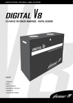
SELLING POINTS
[NEW FEATURES]
Improved overload durability
(improved cooling efficiency)
22-position torque adjustable clutch
Soft-grip handle
Safe and secure
lithium-ion battery (BCL 1415, BCL 1815),
or new Ni-Cd battery (BCC 1412, BCC 1812)
SPECIFICATIONS AND PARTS ARE SUBJECT TO CHANGE FOR IMPROVEMENT.
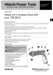
[DV 18DCL2]
International Sales Division
REMARK:
• For more information about HANDLING INSTRUCTIONS, visit our website at:
http://www.hitachi-koki.com/manual_view_export/
• Throughout this TECHNICAL DATA AND SERVICE MANUAL, a symbol(s) is(are) used in the place of
company name(s) and model name(s) of our competitor(s). The symbol(s) utilized here is(are) as follows:
Models DV 18DCL2 and DV 18DVC2
Competitors
Symbols Utilized
R
Company Name
Model Name
RYOBI
CDI-1801
Models DV 14DCL2 and DV 14DVC2
Competitors
Symbols Utilized
R
Company Name
Model Name
RYOBI
CHI-1442
CONTENTS
Page
SELLING POINTS -------------------------------------------------------------------------------------------------------------- 1
SPECIFICATIONS -------------------------------------------------------------------------------------------------------------- 3
1. Specifications --------------------------------------------------------------------------------------------------------------------------------- 3
COMPARISON WITH SIMILAR PRODUCTS---------------------------------------------------------------------------- 7
1. Comparison of Specifications --------------------------------------------------------------------------------- 7
2. Comparison of Drilling and Fastening Performance per Charge ----------------------------------- 11
PRECAUTIONS ON SALES PROMOTION ---------------------------------------------------------------------------- 13
1. Safety Instructions --------------------------------------------------------------------------------------------- 13
2. Inherent Drawbacks of Cordless Impact Driver Drills Requiring
Particular Attention during Sales Promotion ------------------------------------------------------------- 15
REPAIR GUIDE---------------------------------------------------------------------------------------------------------------- 17
1. Precautions on Disassembly and Reassembly --------------------------------------------------------- 17
2. Precautions on Disassembly and Reassembly of the Battery Charger --------------------------- 25
STANDARD REPAIR TIME (UNIT) SCHEDULES-------------------------------------------------------------------- 26
Assembly Diagram for DV 18DCL2
Assembly Diagram for DV 18DVC2
Assembly Diagram for DV 14DCL2
Assembly Diagram for DV 14DVC2
SELLING POINTS
Improved overload durability (improved cooling efficiency)
The Models DV 18DCL2, DV 18DVC2, DV 14DCL2 and DV 14DVC2 ensure durability in continuous
operation, thanks to of a powerful motor and improved air ducts.
• 1.76 N•m {18 kgf•cm} intermittent load test (14.4 V)
• 2.06 N•m {21 kgf•cm} intermittent load test (18 V)
-1-
22-position torque adjustable clutch (Max. clutch torque: 6.0 N•m)
The 22-position torque adjustable clutch ensures fine torque adjustment for better operability.
Clutch dial position
Tightening torque
1
1.0 ± 0.5 N•m {10 ± 5 kgf•cm }
4
1.7 ± 0.6 N•m {17 ± 6 kgf•cm }
10
3.1 ± 0.7 N•m {31 ± 7 kgf•cm }
13
3.8 ± 0.8 N•m {38 ± 8 kgf•cm }
19
5.3 ± 0.9 N•m {53 ± 9 kgf•cm }
22
6.0 ± 1.0 N•m {60 ± 10 kgf•cm }
* There may be some differences in operation depending on shapes of screws and the
workpieces used.
Conduct a test before actual driving.
Soft-grip handle
The handle is widely covered with soft-touch elastomer (rubber-like soft resin). It is slip-resistant and
securely fits in the palm of a hand even if the gripping hand sweats.
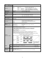
Safe and secure lithium-ion batteries (Types BCL 1815 and BCL 1415)
The new 1.5 Ah Types BCL 1815 and BCL 1415 Lithium-ion Batteries were developed for light-duty work.
Both batteries are equipped with an overdischarge protection circuit, overload protection circuit, overheat
protection circuit and voltage monitoring circuit for each cell to prevent reduced battery service life due to
overdischarge (overuse) or overcharge (excessive charging). These protection circuits make it possible to
safely use the batteries.
Precautions on using the Types BCL 1815 and BCL 1415 Lithium-ion Batteries
The Types BCL 1815 and BCL 1415 Lithium-ion Batteries are both equipped with a protective function that
automatically stops output to prolong battery service life. The motor may stop automatically in any of cases
(1), (2) and (3) below, even if the switch is held down during operation. This is due to activation of the
protective function. The batteries are not faulty.
Protective function
(1)
Overdischarge
protection circuit
Overload
protection circuit
Overheat
(3)
protection circuit
(2)
Source of trouble
Drop in battery voltage to about:
12 V/BCL 1815
8 V/BCL 1415
Corrective action
Charge the battery immediately.
Release the switch and eliminate
the cause of the overload problem.
Remove the battery from the tool
and allow it to cool down.
Heavy-duty work
Continuous operation
or heavy-duty work
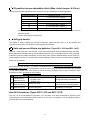
New Ni-Cd batteries (Types BCC 1412 and BCC 1812)
The new 1.2 Ah Ni-Cd Batteries Types BCC 1412 and BCC 1812 were developed for light-duty work.
These batteries—the lowest-level Ni-Cd models of 14.4 V and 18 V batteries—are consequently easier to
purchase than other Ni-Cd batteries.
-2-
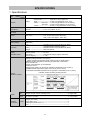
SPECIFICATIONS
1. Specifications
Model
DV 18DCL2
Item
Screw driving Machine screw ------------ 6 mm (1/4")
Wood screw --------------- 8 mm dia. x 75 mm (#20 x 3")
Drilling
Brick ------------------------ 13 mm (1/2") [Depth 30 mm (1-1/4")]
Metal ------- Mild steel --- 13 mm (1/2") [Thickness 1.6 mm (1/16")]
Aluminum -- 13 mm (1/2") [Thickness 1.6 mm (1/16")]
Wood ----------------------- 38 mm (1-1/2") [Thickness 18 mm (11/16")]
Capacity
Keyless chuck
(13VLRS-N)
Rotation speed
(No-load)
Mount type ----------------------Screw-on (UNF 1/2" to 20)
Diameter-------------------------2.0 to 13 mm (5/64" to 1/2")
Low: 0 to 400 min-1, High: 0 to 1,500 min-1
Torque
Slip torque -----------------------1 to 6.0 N•m (10 to 60 kgf•cm, 9 to 52 in-lbs.) [22 stages]
Max. torque ---------------------Low: 43 N•m (439 kgf•cm, 382 in-lbs.)
High: 12 N•m (122 kgf•cm, 106 in-lbs.)
Type of motor
Fan-cooled DC magnet motor
Type of switch
Trigger switch with pushing button for forward and reverse rotation changeover
(with brake)
Enclosure
Battery
(Type BCL 1815)
Charger
(Model UC 18YKL)
Indication method of battery charging function
Net
Main body unit (including battery) ------------------------------------------- 1.6 kg (3.5 lbs.)
Charger unit (UC 18YKL, including cord) ----------------------------------- 0.4 kg (0.9 lb.)
Gross
DV 18DCL2 (2LCKK) - -------------------------------------------------------- 4.1 kg (8.9 lbs.)
2LCKK
Charger (UC 18YKL) ---------------------------------------------------------- 1
Battery (BCL 1815) ------------------------------------------------------------ 2
Phillips (plus) driver bit (No. 2) ----------------------------------------------- 1
Case ---------------------------------------------------------------------------- 1
Weight
Standard
accessories
Body -----------------------------Glassfiber-reinforced polyamide resin (black)
and thermoplastic elastomer (green)
Battery --------------------------Glassfiber-reinforced polyamide resin (black)
Charger -------------------------ABS resin (black)
Sealed cylindrical lithium-ion storage battery
Nominal voltage ----------------DC 18 V
Nominal life ---------------------Charging/discharging: Approx. 800 times
Nominal capacity ---------------1.5 Ah
Overcharge protection system:
(1) Battery voltage detection (∆V system)
Battery temperature detection (dT/dt system) for Ni-Cd, Ni-MH battery
(2) Battery surface temperature detection (by thermostat or thermistor)
(3) 240 minute timer
(4) Stop current detection (Li-ion batteries)
Power input: 50 W
Charging time: Approx. 60 minutes [for Type BCL 1815 Battery at 20°C (68°F)]
Operable ambient temperature range: 0°C to 40°C (32°F to 104°F)
The maximum allowable temperature of the Type BCL 1815 Battery is 50°C (122°F).
-3-
Model
DV 18DVC2
Item
Screw driving Machine screw ------------ 6 mm (1/4")
Wood screw --------------- 8 mm dia. x 75 mm (#20 x 3")
Drilling
Brick ------------------------ 13 mm (1/2") [Depth 30 mm (1-1/4")]
Metal ------- Mild steel --- 13 mm (1/2") [Thickness 1.6 mm (1/16")]
Aluminum -- 13 mm (1/2") [Thickness 1.6 mm (1/16")]
Wood ----------------------- 38 mm (1-1/2") [Thickness 18 mm (11/16")]
Mount type ----------------------Screw-on (UNF 1/2" to 20)
Diameter-------------------------2.0 to 13 mm (5/64" to 1/2")
Capacity
Keyless chuck
(13VLRS-N)
Rotation speed
(No-load)
Low: 0 to 400 min-1, High: 0 to 1,500 min-1
Torque
Slip torque ----------------------1 to 6.0 N•m (10 to 60 kgf•cm, 9 to 52 in-lbs.) [22 stages]
Max. torque ---------------------Low: 43 N•m (439 kgf•cm, 382 in-lbs.)
High: 12 N•m (122 kgf•cm, 106 in-lbs.)
Type of motor
Fan-cooled DC magnet motor
Type of switch
Enclosure
Battery
(Type BCC 1812)
Charger
(Models UC 18YK/
UC 18SF for Ni-Cd
battery only)
Trigger switch with pushing button for forward and reverse rotation changeover
(with brake)
Body -----------------------------Glassfiber-reinforced polyamide resin (black)
and thermoplastic elastomer (green)
Battery --------------------------Glassfiber-reinforced polyamide resin (black)
Charger -------------------------ABS resin (black)
Sealed cylindrical nickel-cadmium storage battery
Nominal voltage ----------------DC 18 V
Nominal life ---------------------Charging/discharging: Approx. 300 times
Nominal capacity --------------1.2 Ah
• Overcharge prevention circuit (UC 18YK only):
A thermostat monitors the battery surface temperature and upon detecting a rise in
temperature that occurs at the end of charging, the unit turns off automatically to prevent
the battery from overcharge.
• Power input: UC 18YK: 50 W, UC 18SF: 24 W
• Indication method: Pilot lamp indicator of battery charging
Function (UC 18YK):On------During charging
Off ------Charging completed
Function (UC 18SF):On ------When inserting a battery
Off ------Disconnecting a battery
Net
Main body unit (including battery) ------------------------------------------- 1.9 kg (4.2 lbs.)
Charger unit (UC 18YK, including cord) ------------------------------------ 0.35 kg (0.8 lb.)
Charger unit (UC 18SF, including cord) ----------------------------------------- 0.6 kg (1.3 lbs.)
Gross
DV 18DVC2 (2SLKK) --------------------------------------------------------- 4.7 kg (10.4 lbs.)
DV 18DVC2 (3SLSK) --------------------------------------------------------- 5.6 kg (12.3 lbs.)
2SLKK
Charger (UC 18YK) ----------------------------------------------------------- 1
Battery (BCC 1812) ------------------------------------------------------------------ 2
Phillips (plus) driver bit (No. 2) ----------------------------------------------- 1
Case ----------------------------------------------------------------------------- 1
3SLSK
Charger (UC 18SF) ----------------------------------------------------------- 1
Battery (BCC 1812) ----------------------------------------------------------- 3
Phillips (plus) driver bit (No. 2) ----------------------------------------------- 1
Case ---------------------------------------------------------------------------- 1
Weight
Standard
accessories
-4-
Model
DV 14DCL2
Item
Screw driving
Drilling
Capacity
Machine screw----------- 6 mm (1/4")
Wood screw ------------- 8 mm dia. x 50 mm (#20 x 2")
Brick ---------------------- 13 mm (1/2") [Depth 30 mm (1-1/4")]
Metal ------ Mild steel --- 13 mm (1/2") [Thickness 1.6 mm (1/16")]
Aluminum -- 13 mm (1/2") [Thickness 1.6 mm (1/16")]
Wood --------------------- 32 mm (1-1/4") [Thickness 18 mm (11/16")]
Mount type ----------------------Screw-on (UNF 1/2" to 20)
Diameter-------------------------2.0 to 13 mm (5/64" to 1/2")
Keyless chuck
(13VLRS-N)
Rotation speed
(No-load)
Low: 0 to 400 min-1, High: 0 to 1,500 min-1
Torque
Slip torque ----------------------1 to 6.0 N•m (10 to 60 kgf•cm, 9 to 52 in-lbs.) [22 stages]
Max. torque ---------------------Low: 37 N•m (378 kgf•cm, 328 in-lbs.)
High: 10 N•m (102 kgf•cm, 89 in-lbs.)
Type of motor
Fan-cooled DC magnet motor
Type of switch
Trigger switch with pushing button for forward and reverse rotation changeover
(with brake)
Enclosure
Body -----------------------------Glassfiber-reinforced polyamide resin (black)
and thermoplastic elastomer (green)
Battery --------------------------Glassfiber-reinforced polyamide resin (black)
Charger -------------------------ABS resin (black)
Battery
(Type BCL 1415)
Sealed cylindrical lithium-ion storage battery
Nominal voltage ----------------DC 14.4 V
Nominal life ---------------------Charging/discharging: Approx. 800 times
Nominal capacity ---------------1.5 Ah
Overcharge protection system:
(1) Battery voltage detection (∆V system)
Battery temperature detection (dT/dt system) for Ni-Cd, Ni-MH battery
(2) Battery surface temperature detection (by thermostat or thermistor)
(3) 240 minute timer
(4) Stop current detection (Li-ion batteries)
Power input: 50 W
Charging time: Approx. 60 minutes [for Type BCL 1415 Battery at 20°C (68°F)]
Operable ambient temperature range: 0°C to 40°C (32°F to 104°F)
The maximum allowable temperature of the Type BCL 1415 Battery is 50°C (122°F).
Charger
(Model UC 18YKL)
Net
Main body unit (including battery) ------------------------------------------- 1.5 kg (3.3 lbs.)
Charger unit (UC 18YKL, including cord) ----------------------------------- 0.4 kg (0.9 lb.)
Gross
DV 14DCL2 (2LCKK) - -------------------------------------------------------- 4.0 kg (8.7 lbs.)
2LCKK
Charger (UC 18YKL) ---------------------------------------------------------- 1
Battery (BCL 1415) ------------------------------------------------------------ 2
Phillips (plus) driver bit (No. 2) ----------------------------------------------- 1
Case ---------------------------------------------------------------------------- 1
Weight
Standard
accessories
Indication method of battery charging function
-5-
Model
DV 14DVC2
Item
Screw driving
Drilling
Capacity
Machine screw----------- 6 mm (1/4")
Wood screw ------------- 8 mm dia. x 50 mm (#20 x 2")
Brick ---------------------- 13 mm (1/2") [Depth 30 mm (1-1/4")]
Metal ------ Mild steel --- 13 mm (1/2") [Thickness 1.6 mm (1/16")]
Aluminum -- 13 mm (1/2") [Thickness 1.6 mm (1/16")]
Wood --------------------- 32 mm (1-1/4") [Thickness 18 mm (11/16")]
Keyless chuck
(13VLRS-N)
Mount type ----------------------Screw-on (UNF 1/2" to 20)
Diameter-------------------------2.0 to 13 mm (5/64" to 1/2")
Rotation speed
(No-load)
Low: 0 to 400 min-1, High: 0 to 1,500 min-1
Torque
Slip torque ----------------------1 to 6.0 N•m (10 to 60 kgf•cm, 9 to 52 in-lbs.) [22 stages]
Max. torque ---------------------Low: 37 N•m (378 kgf•cm, 328 in-lbs.)
High: 10 N•m (102 kgf•cm, 89 in-lbs.)
Type of motor
Fan-cooled DC magnet motor
Type of switch
Trigger switch with pushing button for forward and reverse rotation changeover
(with brake)
Enclosure
Body -----------------------------Glassfiber-reinforced polyamide resin (black)
and thermoplastic elastomer (green)
Battery --------------------------Glassfiber-reinforced polyamide resin (black)
Charger -------------------------ABS resin (black)
Battery
(Type BCC 1412)
Sealed cylindrical nickel-cadmium storage battery
Nominal voltage ----------------DC 14.4 V
Nominal life ---------------------Charging/discharging: Approx. 300 times
Nominal capacity ---------------1.2 Ah
Charger
(Model UC 18YK for
Ni-Cd battery only)
• Overcharge prevention circuit:
A thermostat monitors the battery surface temperature and, upon detecting a rise in
temperature that occurs at the end of charging, the unit turns off automatically to prevent
the battery from overcharge.
• Input capacity: 50 W
• Indication method: Pilot lamp indicator of battery charging
Function: On-------------------When inserting a battery
Off ------------------Charging completed
Net
Main body unit (including battery) ------------------------------------------- 1.8 kg (4.0 lbs.)
Charger unit (UC 18YK, including cord) ------------------------------------ 0.35 kg (0.8 lb.)
Gross
DV 14DVC2 (2SKK) ----------------------------------------------------------- 4.4 kg (9.8 lbs.)
2SKK
Charger (UC 18YK) ----------------------------------------------------------- 1
Battery (BCC 1412) ------------------------------------------------------------------ 2
Phillips (plus) driver bit (No. 2) ---------------------------------------------------- 1
Case -------------------------------------------------------------------------------------- 1
Weight
Standard
accessories
-6-
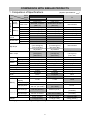
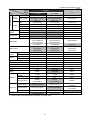
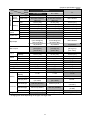
COMPARISON WITH SIMILAR PRODUCTS
1. Comparison of Specifications
Maker
Model
6 mm (1/4”)
8 mm dia. x 75 mm
(#20 x 3”)
13 mm (1/2”)
13 mm (1/2”)
13 mm (1/2”)
38 mm (1-1/2”)
0 to 400 min-1
0 to 1,500 min-1
0 to 5,600 min-1
0 to 21,000 min-1
1.0 to 6.0 N•m
(10 to 60 kgf•cm)
(9 to 52 in-lbs.)
22 positions
6 mm (1/4”)
8 mm dia. x 75 mm
(#20 x 3”)
13 mm (1/2”)
13 mm (1/2”)
13 mm (1/2”)
38 mm (1-1/2”)
0 to 400 min-1
0 to 1,500 min-1
0 to 5,600 min-1
0 to 21,000 min-1
1.0 to 6.0 N•m
(10 to 60 kgf•cm)
(9 to 52 in-lbs.)
22 positions
43 N•m
(439 kgf•cm)
(382 in-lbs.)
Double sleeve
43 N•m
(439 kgf•cm)
(382 in-lbs.)
Double sleeve
13 mm (1/2”)
Variable speed
Equipped
None
Push-button
T-type
Equipped
None
None
13 mm (1/2”)
Variable speed
Equipped
None
Push-button
T-type
Equipped
Equipped
Equipped
1.2 Ah
1.4 Ah
1.5 Ah
18 V
50 min. (UC 18YK)
180 min. (UC 18SF)
18 V
30 min.
(UC 18YG)
18 V
Overall length
234 mm (9-7/32”)
235 mm (9-1/4”)
Overall height
245 mm (9-21/32”)
244 mm (9-19/32”)
Overall width
78 mm (3-5/64”)
1.9 kg (4.2 lbs.)
78 mm (3-5/64”)
2.3 kg (5.1 lbs.)
Max. capacity
Machine screw
Wood screw
Drilling
Rotation
speed
Impact rate
Brick
Mild steel
Aluminum
Soft wood
Low
High
Low
High
Slip torque
Max. torque
Drill
chuck
Type
Capacity
Type
Switch
Electric brake
Automatic spindle lock
Reversing switch
Handle shape
Soft-grip handle
Hook
Strap
Nominal
capacity
Nominal voltage
Charging time*
Weight
R
DV 18DVC
Screw
driving
Dimensions
HITACHI
DV 18DVC2
Item
Battery
(Superior specifications:
*: Charging time varies depending on the type of charger used.
-7-
Not indicated
Not indicated
13 mm (1/2”)
13 mm (1/2”)
Not indicated
38 mm (1-1/2”)
0 to 400 min-1
0 to 1,400 min-1
0 to 5,200 min-1
0 to 18,200 min-1
Not indicated
24 positions
35 N•m
(357 kgf•cm)
(310 in-lbs.)
Double sleeve
13 mm (1/2”)
Variable speed
Equipped
None
Push-button
T-type
Equipped
None
None
60 min.
264 mm
(10-25/64”)
260 mm
(10-15/64”)
72 mm (2-7/8”)
2.5 kg (5.5 lbs.)
)
(Superior specifications:
Maker
Model
DV 18DCL
6 mm (1/4”)
8 mm dia. x 75 mm
(#20 x 3”)
13 mm (1/2”)
13 mm (1/2”)
13 mm (1/2”)
38 mm (1-1/2”)
0 to 400 min-1
0 to 1,500 min-1
0 to 5,600 min-1
0 to 21,000 min-1
1.0 to 6.0 N•m
(10 to 60 kgf•cm)
(9 to 52 in-lbs.)
22 positions
6 mm (1/4”)
8 mm dia. x 75 mm
(#20 x 3”)
13 mm (1/2”)
13 mm (1/2”)
13 mm (1/2”)
38 mm (1-1/2”)
0 to 400 min-1
0 to 1,500 min-1
0 to 5,600 min-1
0 to 21,000 min-1
1.0 to 6.0 N•m
(10 to 60 kgf•cm)
(9 to 52 in-lbs.)
22 positions
43 N•m
(439 kgf•cm)
(382 in-lbs.)
Double sleeve
43 N•m
(439 kgf•cm)
(382 in-lbs.)
Double sleeve
13 mm (1/2”)
Variable speed
Equipped
None
Push-button
T-type
Equipped
None
None
13 mm (1/2”)
Variable speed
Equipped
None
Push-button
T-type
Equipped
Equipped
Equipped
1.5 Ah
1.5 Ah
1.5 Ah
18 V
60 min.
(UC 18YKL)
18 V
40 min.
(UC 18YGL2)
18 V
Overall length
234 mm (9-7/32”)
235 mm (9-1/4”)
Overall height
237 mm (9-21/64”)
236 mm (9-19/64”)
Overall width
81 mm (3-3/16”)
1.6 kg (3.5 lbs.)
81 mm (3-3/16”)
1.8 kg (4.0 lbs.)
Max. capacity
Machine screw
Screw
driving
Wood screw
Brick
Mild steel
Aluminum
Soft wood
Low
High
Low
High
Drilling
Rotation
speed
Impact rate
Slip torque
Max. torque
Drill
chuck
Type
Capacity
Type
Switch
Electric brake
Automatic spindle lock
Reversing switch
Handle shape
Soft-grip handle
Hook
Strap
Nominal
capacity
Nominal voltage
Charging time*
Dimensions
Weight
R
DV 18DCL2
Item
Battery
HITACHI
*: Charging time varies depending on the type of charger used.
-8-
Not indicated
Not indicated
13 mm (1/2”)
13 mm (1/2”)
Not indicated
38 mm (1-1/2”)
0 to 400 min-1
0 to 1,400 min-1
0 to 5,200 min-1
0 to 18,200 min-1
Not indicated
24 positions
35 N•m
(357 kgf•cm)
(310 in-lbs.)
Double sleeve
13 mm (1/2”)
Variable speed
Equipped
None
Push-button
T-type
Equipped
None
None
60 min.
264 mm
(10-25/64”)
260 mm
(10-15/64”)
72 mm (2-7/8”)
2.5 kg (5.5 lbs.)
)
(Superior specifications:
Maker
Model
DV 14DVC
6 mm (1/4”)
8 mm dia. x 50 mm
(#20 x 2”)
13 mm (1/2”)
13 mm (1/2”)
13 mm (1/2”)
32 mm (1-1/4”)
0 to 400 min-1
0 to 1,500 min-1
0 to 5,600 min-1
0 to 21,000 min-1
1.0 to 6.0 N•m
(10 to 60 kgf•cm)
(9 to 52 in-lbs.)
22 positions
37 N•m
(378 kgf•cm)
(328 in-lbs.)
Double sleeve
13 mm (1/2”)
Variable speed
Equipped
None
Push-button
T-type
Equipped
None
None
6 mm (1/4”)
8 mm dia. x 50 mm
(#20 x 2”)
13 mm (1/2”)
13 mm (1/2”)
13 mm (1/2”)
32 mm (1-1/4”)
0 to 400 min-1
0 to 1,500 min-1
0 to 5,600 min-1
0 to 21,000 min-1
1.0 to 6.0 N•m
(10 to 60 kgf•cm)
(9 to 52 in-lbs.)
22 positions
37 N•m
(378 kgf•cm)
(328 in-lbs.)
Double sleeve
13 mm (1/2”)
Variable speed
Equipped
None
Push-button
T-type
Equipped
Equipped
Equipped
1.2 Ah
1.4 Ah
1.7 Ah
14.4 V
50 min.
(UC 18YK)
14.4 V
30 min.
(UC 18YG)
14.4 V
Overall length
234 mm (9-7/32”)
235 mm (9-1/4”)
Overall height
240 mm (9-29/64”)
239 mm (9-25/64”)
Overall width
78 mm (3-5/64”)
1.8 kg (4.0 lbs.)
78 mm (3-5/64”)
2.1 kg (4.6 lbs.)
Max. capacity
Machine screw
Screw
driving
Wood screw
Drilling
Rotation
speed
Impact rate
Brick
Mild steel
Aluminum
Soft wood
Low
High
Low
High
Slip torque
Max. torque
Drill
chuck
Type
Capacity
Type
Switch
Electric brake
Automatic spindle lock
Reversing switch
Handle shape
Soft-grip handle
Hook
Strap
Nominal
capacity
Nominal voltage
Charging time*
Dimensions
Weight
R
DV 14DVC2
Item
Battery
HITACHI
*: Charging time varies depending on the type of charger used.
-9-
Not indicated
Not indicated
13 mm (1/2”)
13 mm (1/2”)
Not indicated
32 mm (1-1/4”)
0 to 400 min-1
0 to 1,400 min-1
0 to 5,200 min-1
0 to 18,200 min-1
Not indicated
24 positions
34 N•m
(347 kgf•cm)
(301 in-lbs.)
Single sleeve
13 mm (1/2”)
Variable speed
Equipped
Equipped
Push-button
T-type
Equipped
None
Equipped
60 min.
258 mm
(10-5/32”)
270 mm
(10-5/8”)
72 mm (2-7/8”)
2.3 kg (5.1 lbs.)
)
(Superior specifications:
Maker
Model
DV 14DCL
6 mm (1/4”)
8 mm dia. x 50 mm
(#20 x 2”)
13 mm (1/2”)
13 mm (1/2”)
13 mm (1/2”)
32 mm (1-1/4”)
0 to 400 min-1
0 to 1,500 min-1
0 to 5,600 min-1
0 to 21,000 min-1
1.0 to 6.0 N•m
(10 to 60 kgf•cm)
(9 to 52 in-lbs.)
22 positions
37 N•m
(378 kgf•cm)
(328 in-lbs.)
Double sleeve
13 mm (1/2”)
Variable speed
Equipped
None
Push-button
T-type
Equipped
None
None
6 mm (1/4”)
8 mm dia. x 50 mm
(#20 x 2”)
13 mm (1/2”)
13 mm (1/2”)
13 mm (1/2”)
32 mm (1-1/4”)
0 to 400 min-1
0 to 1,500 min-1
0 to 5,600 min-1
0 to 21,000 min-1
1.0 to 6.0 N•m
(10 to 60 kgf•cm)
(9 to 52 in-lbs.)
22 positions
37 N•m
(378 kgf•cm)
(328 in-lbs.)
Double sleeve
13 mm (1/2”)
Variable speed
Equipped
None
Push-button
T-type
Equipped
Equipped
Equipped
1.5 Ah
1.5 Ah
1.7 Ah
14.4 V
60 min.
(UC 18YKL)
14.4 V
40 min.
(UC 18YGL2)
14.4 V
Overall length
234 mm (9-7/32”)
235 mm (9-1/4”)
Overall height
233 mm (9-11/64”)
232 mm (9-9/64”)
Overall width
81 mm (3-3/16”)
1.5 kg (3.3 lbs.)
78 mm (3-5/64”)
1.8 kg (4.0 lbs.)
Max. capacity
Machine screw
Screw
driving
Wood screw
Brick
Mild steel
Aluminum
Soft wood
Low
High
Low
High
Drilling
Rotation
speed
Impact rate
Slip torque
Max. torque
Drill
chuck
Type
Capacity
Type
Switch
Electric brake
Automatic spindle lock
Reversing switch
Handle shape
Soft-grip handle
Hook
Strap
Nominal
capacity
Nominal voltage
Charging time*
Dimensions
Weight
R
DV 14DCL2
Item
Battery
HITACHI
*: Charging time varies depending on the type of charger used.
-10-
Not indicated
Not indicated
13 mm (1/2”)
13 mm (1/2”)
Not indicated
32 mm (1-1/4”)
0 to 400 min-1
0 to 1,400 min-1
0 to 5,200 min-1
0 to 18,200 min-1
Not indicated
24 positions
34 N•m
(347 kgf•cm)
(301 in-lbs.)
Single sleeve
13 mm (1/2”)
Variable speed
Equipped
Equipped
Push-button
T-type
Equipped
None
Equipped
60 min.
258 mm
(10-5/32”)
270 mm
(10-5/8”)
72 mm (2-7/8”)
2.3 kg (5.1 lbs.)
)
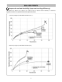
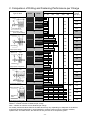
2. Comparison of Drilling and Fastening Performance per Charge
Type of Work
30 mm
ø10
Mortar
Maker
0 *200
0 50
Working Capacity
*400 *600
*800 *1,000
100 150
200 250
Drilling
Speed
(sec./pc.)
DV 18DVC2
31
11.1
DV 18DVC
37
11.3
DV 18DCL2
40
10.9
DV 18DCL
46
11.1
38
10.1
DV 18DVC2
109
3.1
DV 18DVC
127
3.6
DV 18DCL2
136
3.1
DV 18DCL
141
3.1
117
3.1
DV 18DVC2
72
7.0
DV 18DVC
84
7.1
DV 18DCL2
80
6.6
DV 18DCL
80
6.7
75
7.5
DV 18DVC2
77
5.1
DV 18DVC
89
5.4
DV 18DCL2
101
5.0
DV 18DCL
100
5.1
78
5.1
HITACHI
Concrete drill bit
R
<Forward rotation, high
speed, impact drilling>
American pine
Model
T18
ø24
HITACHI
Wood boring
R
<High speed, drilling>
T1.6
ø8
SPCC T1.6
HITACHI
Metal boring
R
<High speed, 15 kg thrust>
L75
HITACHI
ø6
American pine
Coach bolt
(with predrilled holes
4 mm in dia.)
<Low speed, drilling>
Machine screw M6
R
L12
DV 18DVC2
752*
0.5
DV 18DVC
933*
0.5
DV 18DCL2
931*
0.5
DV 18DCL
946*
0.5
920*
0.5
HITACHI
Steel plate
S10C
<High speed, maximum clutch>
R
[Working Capacity]
Without *: Number of holes or fasteners per charge
With *: Number of machine screws fastened per charge
As actually measured values listed in the table above may vary depending on sharpness of the drill bit,
workpiece hardness (particularly in wood materials), moisture content of wood, charging condition,
operator skill, and other factors, this data should only be used as a comparative guide.
-11-
Type of Work
30 mm
ø8
Mortar
Maker
0 *200
0 50
Drilling
Speed
(sec./pc.)
DV 14DVC2
38
9.5
DV 14DVC
38
9.4
DV 14DCL2
45
9.8
DV 14DCL
44
9.2
46
9.1
DV 14DVC2
129
3.2
DV 14DVC
161
3.4
DV 14DCL2
155
3.2
DV 14DCL
176
3.2
188
3.4
DV 14DVC2
69
6.2
DV 14DVC
81
6.3
DV 14DCL2
79
6.2
DV 14DCL
79
6.3
91
7.5
DV 14DVC2
112
3.4
DV 14DVC
121
3.5
DV 14DCL2
144
3.2
DV 14DCL
140
3.2
145
3.7
DV 14DVC2
610*
0.5
DV 14DVC
679*
0.5
DV 14DCL2
717*
0.5
DV 14DCL
744*
0.5
650*
0.5
HITACHI
Concrete drill bit
R
<Forward rotation, high
speed, impact drilling>
American pine
Model
Working Capacity
*400 *600
*800 *1,000
100 150
200 250
T18
ø18
HITACHI
Wood boring
R
<High speed, drilling>
T1.6
ø6.5
SPCC T1.6
HITACHI
Metal boring
R
<High speed, 15 kg thrust>
L40
HITACHI
ø4.8
American pine
Coach bolt
(with predrilled holes
4 mm in dia.)
R
<Low speed, drilling>
Machine screw M6
L12
HITACHI
Steel plate
S10C
<High speed, maximum clutch>
R
[Working Capacity]
Without *: Number of holes or fasteners per charge
With *: Number of machine screws fastened per charge
As actually measured values listed in the table above may vary depending on sharpness of the drill bit,
workpiece hardness (particularly in wood materials), moisture content of wood, charging condition,
operator skill, and other factors, this data should only be used as a comparative guide.
-12-
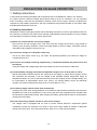
PRECAUTIONS ON SALES PROMOTION
1. Safety Instructions
In the interest of promoting the safest and most efficient use of the Models DV 18DCL2, DV 18DVC2,
DV 14DCL2 and DV 14DVC2 Cordless Impact Driver Drills by all of our customers, it is very important
when concluding a sale that the salesperson carefully ensure that the buyer seriously recognizes the
importance of the Handling Instructions, and fully understands the precautions listed on the Caution Plate
and Nameplate attached to each tool.
A. Handling instructions
Salespersons must be thoroughly familiar with the Handling Instructions in order to give pertinent advice to
the customer. In particular, they must have a thorough understanding of the precautions on using cordless
tools that differ from those of ordinary electric power tools.
(1) Before use, ensure that the unit is fully charged.
New units are not fully charged. Even if the units were fully charged at the factory, long periods of
inactivity, such as during shipment, cause the storage battery to lose its charge. Customers must be
instructed to fully charge the unit prior to use.
(2) Connect the charger to an AC power outlet only.
Use of any other power source (e.g., DC outlet, fuel powered generator) will cause the charger to
overheat and burn out.
(3) Do not use any voltage-increasing equipment (e.g., transformer) between the power source and
the charger.
Using the charger with voltage higher than that indicated on the unit will result in malfunction.
(4) Conduct battery charging at an ambient temperature range of 10°C to 40°C (50°F to 104°F).
Special temperature-sensitive devices are employed in the charger to permit rapid charging. Ensure
that customers are instructed to use the charger at the indicated ambient temperature range. At
temperatures below 10°C (50°F) the thermostat will not function properly, and the storage battery may
be overcharged. At temperatures above 40°C (104°F), the storage battery cannot be sufficiently
charged. The optimum temperature range is 20°C to 25°C (68°F to 77°F).
(5) The battery charger should not be used continuously.
Charging more than three storage batteries in succession at high ambient temperature will cause the
temperature of coils on the transformer to rise, running the risk of the temperature fuse inserted inside
the transformer inadvertently melting. After charging one battery, please wait at least 15 minutes before
charging the next battery.
(6) Do not insert foreign objects into the air vents on the charger.
The charger case is equipped with air vents to protect internal electronic components against
overheating. Caution the customer not to drop or insert such foreign matter as metallic or flammable
objects into the air vents. This could cause electric shock, fire, or other serious hazards.
-13-
(7) Do not attempt to disassemble the storage battery or the charger.
Special devices such as a thermostat are built into the storage battery and charger to permit rapid
charging. Incorrect parts replacement and/or wiring will cause malfunctions that could result in fire or
other hazards. Instruct the customer to bring these units to an authorized service center in the event
repair or replacement is necessary.
(8) Disposal of the storage battery
Ensure that all customers understand that the storage batteries should be returned to the Hitachi power
tool sales outlet or authorized service center when no longer capable of being recharged or repaired. If
thrown into a fire, the batteries may explode.
B. Caution plates
(1) The following cautions are listed on the nameplate attached to the main body of each tool.
[For the USA and Canada]
Warning
• To reduce the risk of injury, user must read Instruction Manual.
AVERTISSEMENT
• Afin de réduire le risque de blessures, I’utilisateur doit lire le mode d’emploi.
(2) The following cautions are listed on the nameplate attached to each storage battery.
[For Europe]
[For the USA and Canada]
(3) The following cautions are listed on the nameplate attached to the Model UC 18YK Charger.
[For the USA and Canada]
-14-
2. Inherent Drawbacks of Cordless Impact Driver Drills Requiring
Particular Attention during Sales Promotion
The cordless impact driver drill offers many advantages; it can be used in places where no power source is
available, the absence of a cord allows easy use, etc. However, any cordless tool has certain inherent
drawbacks. Salespersons must be thoroughly familiar with these drawbacks in order to properly advise the
customer in the most efficient use of the tool.
A. Suggestions and precautions on efficient use of the tool
(1) Use the cordless impact driver drill for comparatively light work.
The motor output of battery driven cordless impact driver drills is rather low compared with conventional
electric power tools. Accordingly, they are not suitable for the continuous drilling of many holes in
succession, or for drilling into particularly hard material that imposes a heavy load. Salespersons should
recommend conventional electric power tools for such heavy work.
(2) Large-diameter holes should be drilled at low speed.
Instruct the customer that drilling large-diameter holes or performing other work that requires
particularly strong torque should be done at low speed. Because there is less torque at high speed,
attempting such work at high speed will not improve working efficiency.
(3) Do not insert a foreign object into body vent holes.
The body of this tool has vent holes for improved cooling efficiency. As a fan is built into the motor, a
foreign object inserted through a vent hole may cause failure. Please instruct customers to never insert
a foreign object into the vent holes.
(4) Use at thrust of 100 to 150 N (10 to 15 kgf, 22 to 23 lbs.)
The drilling speed of this unit does not accelerate even if the tool is pressed strongly against the
workpiece as when using a typical AC impact drill. Such operation will damage the drill bit, resulting in
not only poor working efficiency but also motor burnout.
(5) Avoid “locking” of the motor
Locking of the motor will generate an overload current that could result in motor burnout and/or rapid
battery deterioration. Salespersons should advise the customer to immediately release the switch and
stop operation if the motor becomes locked. (A jammed drill bit can be disengaged from the workpiece
material by setting the switch to reverse rotation, or by manually turning the main body of the tool.)
(6) Variation in amount of work possible per charge
Although the nominal chargeable capacity of the storage batteries used with the Models DV 18DCL2,
DV 18DVC2, DV 14DCL2 and DV 14DVC2 is 1.2 Ah or 1.5 Ah, the actual capacity may vary within 10%
of that value depending on ambient temperature during use and charging, and the number of times the
batteries have been recharged. It should be noted that other factors that may affect the amount of work
possible per charge are the working conditions (e.g., ambient temperature, type and moisture content of
the workpiece, sharpness of the drill bit) and the operational skill of the user.
-15-
(7) Precautions on the use of HSS drill bits
For example, although the Model DV 18DCL2 is designed for drilling capacities of 38 mm (1-1/2") in
wood, and 13 mm (1/2") in aluminum and mild steel, this capability is not as efficient as conventional
electric power tools. In particular, when drilling through aluminum material with a 13 mm (1/2") drill bit,
the drill tends to become locked when the drill bit penetrates a material. For this reason, the customer
should be cautioned to reduce the thrust on the main body of the drill when drilling completely through a
material to avoid locking the tool. Repeated locking of the drill causes excessive current to flow from the
battery, thereby not only reducing the amount of work possible per charge, but also running the risk of
motor burnout.
(8) Securely tighten the sleeve of the keyless chuck.
The keyless chuck may slip during operation when using a cylindrically shaped drill bit shank,
depending on the surface conditions, materials, and other factors. Please instruct customers to
retighten the keyless chuck more securely if the keyless chuck slips during operation. The holding force
of the keyless chuck increases as you increase the tightening force of the keyless chuck.
(9) Avoid continuous use.
Although the Models DV 18DCL2, DV 18DVC2, DV 14DCL2 and DV 14DVC2 can withstand continuous
operation under certain conditions, operating conditions differ depending on the workpiece material and
sharpness of the drill bit in use. Please instruct customers to avoid continuous use of the Models DV
18DCL2, DV 18DVC2, DV 14DCL2 and DV 14DVC2, and generally take about a 15 minute break
following a single charge operation.
-16-
REPAIR GUIDE
Be sure to remove the storage batteries from the main body before servicing. Inadvertent triggering of the
switch with the storage battery connected imposes the danger of the motor accidently turning.
1. Precautions on Disassembly and Reassembly
[Bold] numbers in the descriptions below correspond to item numbers in the Parts List and exploded
assembly diagrams for the Models DV 18DCL2, DV 18DVC2, DV 14DCL2 and DV 14DVC2.
Disassembly
1. Removal of Housing (A).(B) Set
First, align the drill mark "
" on the Clutch Dial [4] with the triangle mark on Housing (A).(B) Set [33].
Remove the eight Tapping Screw (W/Flange) D3 x 16 (Black) [38] from the main body. Gently open
Housings (A) and (B) while holding the battery loading sections.
2. Removal of internal parts
After removal of Housing (B), all internal parts (assembled or separated) can be taken out as a single unit.
Lift the entire contents from Housing (A) while holding the Motor [36] and Clutch Dial [4].
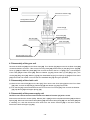
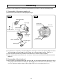
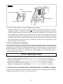
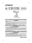
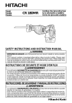
3. Removal of the Drill Chuck 13VLRS-N (See Fig. 1.)
(a) Turn the Motor [36] counterclockwise (when viewed from the rear) and remove it from the Rear Case
[22]. Remove the Shift Knob [37] from the Shift Arm [24]. Be careful not to remove the Shift Arm [24]
from the Rear Case [22] in this operation.
(b) Attach the motor spacer to the assembly of the Drill Chuck 13VLRS-N [2], Clutch Dial [4], Front Case
[15] and Rear Case [22], and then mount the assembly on special repair tool J-348 clamped in the vise
as illustrated in Fig. 1. In this operation, confirm that the pinions press-fitted in the special repair tool J342 and Planet Gear (A) Set [27] are properly engaged.
(c) Secure the Slide Ring Gear [25] to the Front Case [15] side with the Shift Arm [24].
(d) Turn the sleeve of the Drill Chuck 13VLRS-N [2] counterclockwise (when viewed from the front) to fully
open the jaws of the Drill Chuck 13VLRS-N [2]. Turn Flat Hd. Screw (A) (Left Hand) M6 x 25 [1]
clockwise and remove it. (Note that the special screw is left-hand threaded.)
(e) Fit the hexagonal bar wrench M10 into the Drill Chuck 13VLRS-N [2] as illustrated in Fig. 1, and then
turn the wrench counterclockwise to remove the Drill Chuck 13VLRS-N [2].
-17-
Fig. 1
Drill Chuck 13VLRS-N [2]
Hexagonal bar wrench
Clutch Dial [4]
Front Case [15]
Slide Ring Gear [25]
Shift Arm [24]
Rear Case [22]
Vise
Special repair tool (J-348)
4. Disassembly of the gear unit
Remove the Shift Arm [24] from the Rear Case [22]. Turn Washer (B) [30] mounted in the Rear Case [22]
counterclockwise to remove it. Take out the First Ring Gear [29], Planet Gear (A) Set [27], Pinion (B) [28],
Pinion (C) [26] and Slide Ring Gear [25]. Then remove the Screw Set D3 x 12 [23] (4 pcs.) connecting the
Front Case [15] and Rear Case [22]. Remove Washer (A) [21], Planet Gear (C) Set [20] (3 pcs.), the
Carrier [19], Ring Gear [18], Washer (A) [10], four Steel Balls D5 [17], four Springs (A) [16] and Front Case
[15] in that order. Be careful not to lose the four Steel Balls D5 [17] during this operation.
5. Disassembly of the clutch unit
(a) Remove the Clutch Dial [4] from the Nut [11]. Then remove the Click Spring [5] from the Front Case
[15]. Next, remove the Spindle [7], Ratchet (B) [9] and Washer (A) [10] in that order.
(b) Turn the Nut [11] counterclockwise and remove it from the Front Case [15]. Then remove the Washer
[12], Slip Block [13] and Stopper Spring [14].
6. Disassembly of the power supply unit
NOTE: Do not remove the heat sink secured to the Switch Terminal [41] with a screw.
Remove the two Machine Screws (W/Sp. Washer) M4 x 6 [32], and then separate the Motor [36] and Motor
Spacer [31]. Disconnect the Internal Wire (Black) [40] and Internal Wire (Red) [42] from the Motor [36] with
a soldering iron, and then disconnect both wires from the Switch Terminal [41] in the same manner.
Disconnect Terminal Support (A) [43].
-18-
Reassembly
Generally conduct reassembly by reversing the disassembly procedures, and note the following items:
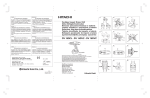
1. Reassembly of the power supply unit
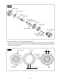
(a) Perform wiring according to the wiring diagram (Fig. 2).
Fig. 3
Fig. 2
Motor Spacer [31]
Motor [36]
Positive side
Red mark
Internal Wire
(Black) [40]
Machine Screw
(W/Sp. Washer) M4 x 6 [32]
Internal Wire
(Red) [42]
Negative side
Switch Terminal [41]
Terminal Support
(A) [43]
Terminal
(b) Pay attention to the polarity of the Motor [36] when soldering the Internal Wire (Black) [40] and Internal
Wire (Red) [42] to the Motor [36]. The red-marked side of the Motor [36] is positive. (See Fig. 3.)
(c) Insert the terminal while being careful about the direction of Terminal Support (A) [43].
(d) Apply grease (Hitachi Motor Grease No. 29, Code No. 930035 recommended) to the press-fitted Motor
[36] shaft.
2. Reassembly of the clutch unit
(a) Mount Washer (A) [10], Ratchet (B) [9], Spring (C) [8], the Spindle [7] and Washer [12] onto the Front
Case [15] in that order. When mounting the Spindle [7], press in the outside of the ball bearing. Then
mount the Slip Block [13] and Stopper Spring [14] inside the Front Case [15]. (See Fig. 4.)
-19-
Fig. 4
Clutch Dial [4]
Click Spring [5]
O-ring [6]
Spindle [7]
Spring (C) [8]
Ratchet (B) [9]
Nut [11]
Washer [12]
Washer (A) [10]
Front Case [15]
Slip Block [13]
Stopper Spring [14]
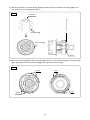
(b) Mount the Nut [11] onto the Front Case [15]. (See Fig. 5.)
Align rib (A) on the Front Case [15] with short interval (B) on the Nut [11]. Rotate the Nut [11] about
one-half turn clockwise so that rib (A) on the Front Case [15] and short interval (B) on the Nut [11] are
positioned on opposite sides.
Fig. 5
Front Case [15]
(B)
Nut [11]
One-half turn
clockwise
Rib (A)
Short interval (B)
-20-
(A)
(c) With the protrusion on the Click Spring [5] facing upward, securely insert the Click Spring [5] into the
groove of the Front Case [15]. (See Fig. 6.)
Fig. 6
Protrusion
Click Spring [5]
Front Case [15]
Groove
(d) Mount the Clutch Dial [4] onto the Front Case [15]. (See Fig. 7.) Mount the Nut [11] onto the Clutch Dial
[4] by aligning the ribs on the Clutch Dial [4] with the grooves on the Nut [11].
Fig. 7
Groove
Rib
Rib
Groove
-21-
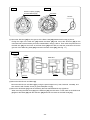
3. Reassembly of the gear unit
(a) Apply grease (Hitachi Motor Grease No. 29, Code No. 930035) to the meshing portions of each gear.
(b) Reassemble the parts of the gear unit in order. (See Fig. 8.)
Fig. 8
Spring (A) [16]
Steel Ball D5 [17]
Washer (A) [10]
Ring Gear [18]
Carrier [19]
Planet Gear (C) Set [20]
Washer (A) [21]
Rear Case [22]
Shift Arm [24]
Slide Ring Gear [25]
Pinion (C) [26]
Screw Set
D3 x 12 [23]
Planet Gear (A) Set [27]
Pinion (B) [28]
Planet Gear (A) Set [27]
Groove
First Ring Gear [29]
Washer (B) [30]
(1) Position Spring (A) [16] (4 pcs.) and Steel Ball D5 [17] (4 pcs.) as illustrated in Fig. 9.
(2) Pay attention to the direction of the groove when mounting the Slide Ring Gear [25], so that the
groove faces toward the Motor [36].
(3) Mount the Front Case [15] and Rear Case [22] so that the positioning groove matches the rib.
(4) Fit Washer (B) [30] in the Rear Case [22] so that the protrusions of Washer (B) [30] fit into the
recesses on the Rear Case [22]. Then fully turn Washer (B) [30] clockwise until it stops.
(See Fig. 10.)
-22-
Fig. 9
Fig. 10
Position of Spring (A) [16]
and Steel Ball D5 [17]
Recesses
Recess
Recess
(c) Mount the Shift Arm [24] into the groove of the Rear Case [22] reassembled in step (b) above.
Facing the ridge of the Shift Arm [24] toward the Motor [36] side, mount the Shift Arm [24] on the
unmarked side of the assembly that was reassembled in step (b) above. Then insert the protrusions of
the Shift Arm [24] into the holes of the Rear Case [22] and make sure that the protrusions fit into the
grooves of the Slide Ring Gear [25] mounted in the Rear Case [22]. (See Fig. 11.)
Fig. 11
Ridge
Hole
View of C
Mark
C
Groove
(d) Mount the Drill Chuck 13VLRS-N [2].
Mount the Drill Chuck 13VLRS-N [2] by using the special repair tool (J-348, Code No. 349-886), and
then secure it with Flat Hd. Screw (A) (Left Hand) M6 x 25 [1].
(e) Mount the Shift Knob [37] onto the assembly that was reassembled in step (d) above.
When mounting the Shift Knob [37] to the Shift Arm [24], check that the “LOW” mark on the Shift Knob
[37] faces the Motor [36] with the Shift Arm [24] fitted into the recess of the Shift Knob [37].
-23-
(f) Mount the assembly that was reassembled in step (1)
and the assembly reassembled in step (e) above
together. (See Fig. 12.) Fit the protrusion of the Motor
Fig. 12
Spacer [31] into the recess of the Rear Case [22],
while ensuring that the Shift Knob [37] is aligned with
the positive side of the Motor [36]. Turn the Motor
Spacer [31] clockwise as viewed from the rear of the
Motor [36] until it stops. During reassembly, make sure
that the pinions press-fitted onto the shaft of the Motor
Protrusion
Recess
[36] and Planet Gear (A) Set [27] mesh properly.
4. Mounting the assembly reassembled in step (3) to Housing (A).(B) Set
(a) Mount the assembly that was reassembled in step (3) above to Housing (A). Confirm that the
protrusions of the Front Case [15] and Motor Spacer [31] are engaged in the recesses of Housing (A),
and that the protrusions of Housing (A) fit into the groove of the Clutch Dial [4]. (See Fig. 13.)
Fig. 13
Protrusion
Groove
Recess
Protrusion
Housing (A)
(b) Mount the Switch Terminal [41] to Housing (A). Insert Terminal Support (A) [43] to Housing (A), while
being careful about the positioning of internal wires of the Switch Terminal [41]. (See Fig. 14.)
(c) Mount the Pushing Button [35] to Housing (A). Confirm that the protrusion of the forward/reverse
changeover lever of the Switch Terminal [41] is inserted into the groove of the Pushing Button [35].
(d) Mount the assembly that was reassembled in step (c) above to Housing (B), and then secure both with
the nine Tapping Screw (W/Flange) D3 x 16 (Black) [38].
-24-
Fig. 14
D-D
Internal Wire (Red) [42]
Internal Wire (Black) [40]
Switch Terminal [41]
Terminal Support (A) [43]
(e) Check for proper operation of the Clutch Dial [4] and Shift Knob [37].
When the reassembly procedure up to step (d) is completed, ensure that every indication on the Clutch
" can be aligned with the triangle mark on Housing
Dial [4] from number "1" to the hammer mark "
(A).(B) Set [33], respectively, and that the Clutch Dial [4] turns moderately. If any indication on the
Clutch Dial [4] cannot be aligned with the triangle mark on Housing (A).(B) Set [33], correctly remount
the improperly mounted Clutch Dial [4] according to step (2). Check for proper operation of the Shift
Knob [37]. Confirm that the speed changes properly between high and low by shifting the Shift Knob
[37]. If the speed does not change properly or moderately, correctly remount the improperly mounted
Shift Knob [37] according to step (3).
5. Other precautions on reassembly
After completing reassembly, confirm that the rotating direction of the Drill Chuck 13VLRS-N [2] matches
the position of the Pushing Button [35]. When the Pushing Button [35] is pressed from the (R) side, the
rotating direction of the Drill Chuck 13VLRS-N [2] should be clockwise as viewed from behind. Switch the
Models DV 18DCL2, DV 18DVC2, DV 14DCL2 or DV 14DVC2 on and off by using the battery. Use a 12
mm dia. test bar to confirm that runout of the Drill Chuck 13VLRS-N [2] is 0.8 mm or less at the position 110
mm away from the tip of the chuck.
Screw Tightening Torque
• Flat Hd. Screw (A) (Left Hand) M6 x 25 [1] ---------------------------• Drill Chuck 13VLRS-N [2] -------------------------------------------------• Screw Set D3 x 12 [23] ----------------------------------------------------• Machine Screw (W/Sp. Washer) M4 x 6 [32] -------------------------• Tapping Screw (W/Flange) D3 x 16 (Black) [38] ----------------------
3.9 to 4.9 N•m (40 to 50 kgf•cm)
17.6 to 21.6 N•m (180 to 220 kgf•cm)
0.6 to 1.0 N•m (6 to 10 kgf•cm)
1.1 to 1.9 N•m (11 to 19 kgf•cm)
1.0 to 1.5 N•m (10 to 15 kgf•cm)
2. Precautions on Disassembly and Reassembly of the Battery Charger
Please refer to the Technical Data and Service Manual for precautions on the disassembly and reassembly
of Battery Charger Models UC 18YKL, UC 18YK and UC 18SF.
-25-
STANDARD REPAIR TIME (UNIT) SCHEDULES
MODEL
Variable
Fixed
10
20
30
Work Flow
DV 18DCL2
Housing
(A).(B) Set
DV 18DVC2
General assembly
Motor
Switch
Terminal Set
Shift Knob
DV 14DCL2
DV 14DVC2
Gear Box
Ass'y
Drill Chuck
13VLRS-N
-26-
Clutch Dial
Spindle
Spring
Ratchet (B)
Nut
Front Case
Ring Gear
Carrier
Planet
Gear (C) Set
Rear Case
Shift Arm
Slide Ring
Gear
Pinion (C)
Planet
Gear (A) Set
Pinion (B)
First Ring Gear
40
50
60 min.
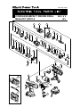
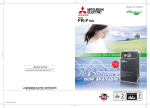
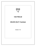
LIST NO. H867
CORDLESS IMPACT DRIVER DRILL
Model DV 18DCL2
1
2
2010 • 6 • 9
(E1)
3
8
9
10
4
11
5
12
6
13
14
7
15
25
16
26
17
27
10
28
18
27
19
29
20
30
21
31
22
23
24
38
39
32
37
36
501
33
35
40
42
502
41
34
503
43
44
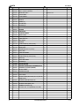
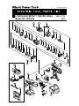
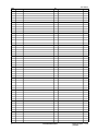
PARTS
ITEM
NO.
DV 18DCL2
CODE NO.
DESCRIPTION
NO.
USED
1
995-344
FLAT HD. SCREW (A) (LEFT HAND) M6 X 25
1
2
332-049
DRILL CHUCK 13VLRS-N
1
3
332-008
GEAR BOX ASS'Y
1
4
332-015
CLUTCH DIAL
1
5
327-146
CLICK SPRING
1
6
327-142
O-RING
1
7
332-010
SPINDLE
1
8
327-136
SPRING (C)
1
9
327-134
RATCHET (B)
1
10
327-147
WASHER (A)
2
11
327-145
NUT
1
12
332-016
WASHER
1
13
327-135
SLIP BLOCK
2
14
327-133
STOPPER SPRING
2
15
332-009
FRONT CASE
1
16
332-018
SPRING (A)
4
17
306-936
STEEL BALL D5
4
18
328-055
RING GEAR
1
19
332-011
CARRIER
1
20
312-705
PLANET GEAR (C) SET (3 PCS.)
3
21
312-704
WASHER (A)
1
22
327-140
REAR CASE
1
23
324-357
SCREW SET D3 X 12 (4 PCS.)
4
24
332-017
SHIFT ARM
1
25
332-013
SLIDE RING GEAR
1
26
332-012
PINION (C)
1
27
332-019
PLANET GEAR (A) SET (6 PCS.)
6
28
332-014
PINION (B)
1
29
332-023
FIRST RING GEAR
1
30
312-716
WASHER (B)
1
31
312-698
MOTOR SPACER
1
32
317-333
MACHINE SCREW (W/SP. WASHER) M4 X 6
2
33
332-039
HOUSING (A). (B) SET (GREEN)
1
34
330-719
HITACHI LABEL
1
35
332-836
PUSHING BUTTON
1
36
332-020
MOTOR DC 18V
1
37
332-036
SHIFT KNOB
1
38
313-687
TAPPING SCREW (W/FLANGE) D3 X 16 (BLACK)
9
NAME PLATE
1
1
39
40
332-843
INTERNAL WIRE (BLACK) 130L
41
332-842
SWITCH TERMINAL SET
1
42
324-499
INTERNAL WIRE (RED) 140L
1
43
315-141
TERMINAL SUPPORT (A)
1
44
327-731
BATTERY BCL 1815 (EUROPE, AUS, NZL)
2
-2-
*ALTERNATIVE PARTS
REMARKS
INCLUD. 4-31
6 - 10
STANDARD ACCESSORIES
ITEM
NO.
CODE NO.
501
DV 18DCL2
DESCRIPTION
NO.
USED
CHARGER (MODEL UC 18YKL)
1
502
983-006
+ DRIVER BIT NO. 2 65L
1
503
332-022
CASE (BLACK)
1
6 - 10
*ALTERNATIVE PARTS
REMARKS
-3-
DV 18DCL2
ITEM
NO.
-4-
CODE NO.
DESCRIPTION
NO.
USED
*ALTERNATIVE PARTS
REMARKS
Printed in Japan
(100609N)
6 - 10
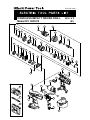
LIST NO. H869
CORDLESS IMPACT DRIVER DRILL
Model DV 18DVC2
1
2
2010 • 6 • 14
(E1)
3
8
9
10
4
11
5
12
6
13
14
7
15
25
16
26
17
27
10
28
18
27
19
29
20
30
21
31
22
23
24
38
39
32
501
37
36
33
501
35
40
42
502
41
34
503
43
44
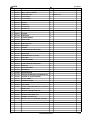
PARTS
ITEM
NO.
DV 18DVC2
CODE NO.
DESCRIPTION
NO.
USED
REMARKS
1
995-344
FLAT HD. SCREW (A) (LEFT HAND) M6 X 25
1
*
2
332-049
DRILL CHUCK 13VLRS-N
1
*
2
322-625
DRILL CHUCK 13VLRJ-N (W/O CHUCK WRENCH)
1
FOR USA, CAN
3
332-008
GEAR BOX ASS'Y
1
INCLUD. 4-31
4
332-015
CLUTCH DIAL
1
5
327-146
CLICK SPRING
1
6
327-142
O-RING
1
7
332-010
SPINDLE
1
8
327-136
SPRING (C)
1
9
327-134
RATCHET (B)
1
10
327-147
WASHER (A)
2
11
327-145
NUT
1
12
332-016
WASHER
1
13
327-135
SLIP BLOCK
2
14
327-133
STOPPER SPRING
2
15
332-009
FRONT CASE
1
16
332-018
SPRING (A)
4
17
306-936
STEEL BALL D5
4
18
328-055
RING GEAR
1
19
332-011
CARRIER
1
20
312-705
PLANET GEAR (C) SET (3 PCS.)
3
21
312-704
WASHER (A)
1
22
327-140
REAR CASE
1
23
324-357
SCREW SET D3 X 12 (4 PCS.)
4
24
332-017
SHIFT ARM
1
25
332-013
SLIDE RING GEAR
1
26
332-012
PINION (C)
1
27
332-019
PLANET GEAR (A) SET (6 PCS.)
6
28
332-014
PINION (B)
1
29
332-023
FIRST RING GEAR
1
30
312-716
WASHER (B)
1
31
312-698
MOTOR SPACER
1
32
317-333
MACHINE SCREW (W/SP. WASHER) M4 X 6
2
*
33
332-039
HOUSING (A). (B) SET (GREEN)
1
*
33
332-985
HOUSING (A). (B) SET (GREEN)
1
34
330-719
HITACHI LABEL
1
35
332-836
PUSHING BUTTON
1
36
332-020
MOTOR DC 18V
1
37
332-036
SHIFT KNOB
1
38
313-687
TAPPING SCREW (W/FLANGE) D3 X 16 (BLACK)
9
NAME PLATE
1
40
332-843
INTERNAL WIRE (BLACK) 130L
1
41
332-038
SWITCH TERMINAL
1
42
324-499
INTERNAL WIRE (RED) 140L
1
43
315-141
TERMINAL SUPPORT (A)
1
*
44
332-083
BATTERY BCC 1812 (EUROPE, AUS, NZL)
2
*
44
332-583
BATTERY BCC 1812 (USA)
2
*
44
332-083
BATTERY BCC 1812 (EUROPE, AUS, NZL)
3
39
-2-
*ALTERNATIVE PARTS
FOR USA, CAN
FOR GBR
6 - 10
STANDARD ACCESSORIES
ITEM
NO.
CODE NO.
DV 18DVC2
DESCRIPTION
NO.
USED
*
501
CHARGER (MODEL UC 18YK)
1
*
501
CHARGER (MODEL UC 18SF)
1
502
983-006
+ DRIVER BIT NO. 2 65L
1
503
332-022
CASE (BLACK)
1
6 - 10
*ALTERNATIVE PARTS
REMARKS
-3-
DV 18DVC2
ITEM
NO.
-4-
CODE NO.
DESCRIPTION
NO.
USED
*ALTERNATIVE PARTS
REMARKS
Printed in Japan
(100614N)
6 - 10
LIST NO. H866
CORDLESS IMPACT DRIVER DRILL
Model DV 14DCL2
1
2
2010 • 6 • 9
(E1)
3
8
9
10
4
11
5
12
6
13
14
7
15
25
16
26
17
27
10
28
18
27
19
29
20
30
21
31
22
23
24
38
39
32
37
36
33
35
501
40
42
41
502
34
503
43
44
PARTS
ITEM
NO.
DV 14DCL2
CODE NO.
DESCRIPTION
NO.
USED
1
995-344
FLAT HD. SCREW (A) (LEFT HAND) M6 X 25
1
2
332-049
DRILL CHUCK 13VLRS-N
1
3
332-008
GEAR BOX ASS'Y
1
4
332-015
CLUTCH DIAL
1
5
327-146
CLICK SPRING
1
6
327-142
O-RING
1
7
332-010
SPINDLE
1
8
327-136
SPRING (C)
1
9
327-134
RATCHET (B)
1
10
327-147
WASHER (A)
2
11
327-145
NUT
1
12
332-016
WASHER
1
13
327-135
SLIP BLOCK
2
14
327-133
STOPPER SPRING
2
15
332-009
FRONT CASE
1
16
332-018
SPRING (A)
4
17
306-936
STEEL BALL D5
4
18
328-055
RING GEAR
1
19
332-011
CARRIER
1
20
312-705
PLANET GEAR (C) SET (3 PCS.)
3
21
312-704
WASHER (A)
1
22
327-140
REAR CASE
1
23
324-357
SCREW SET D3 X 12 (4 PCS.)
4
24
332-017
SHIFT ARM
1
25
332-013
SLIDE RING GEAR
1
26
332-012
PINION (C)
1
27
332-019
PLANET GEAR (A) SET (6 PCS.)
6
28
332-014
PINION (B)
1
29
332-023
FIRST RING GEAR
1
30
312-716
WASHER (B)
1
31
312-698
MOTOR SPACER
1
32
317-333
MACHINE SCREW (W/SP. WASHER) M4 X 6
2
33
332-042
HOUSING (A). (B) SET (GREEN)
1
34
330-719
HITACHI LABEL
1
35
332-836
PUSHING BUTTON
1
36
332-021
MOTOR DC 14.4V
1
37
332-036
SHIFT KNOB
1
38
313-687
TAPPING SCREW (W/FLANGE) D3 X 16 (BLACK)
9
NAME PLATE
1
1
39
40
332-843
INTERNAL WIRE (BLACK) 130L
41
332-842
SWITCH TERMINAL SET
1
42
324-499
INTERNAL WIRE (RED) 140L
1
43
315-141
TERMINAL SUPPORT (A)
1
44
327-729
BATTERY BCL 1415 (EUROPE, AUS, NZL)
2
-2-
*ALTERNATIVE PARTS
REMARKS
INCLUD. 4-31
6 - 10
STANDARD ACCESSORIES
ITEM
NO.
CODE NO.
501
DV 14DCL2
DESCRIPTION
NO.
USED
CHARGER (MODEL UC 18YKL)
1
502
983-006
+ DRIVER BIT NO. 2 65L
1
503
332-022
CASE (BLACK)
1
6 - 10
*ALTERNATIVE PARTS
REMARKS
-3-
DV 14DCL2
ITEM
NO.
-4-
CODE NO.
DESCRIPTION
NO.
USED
*ALTERNATIVE PARTS
REMARKS
Printed in Japan
(100609N)
6 - 10
LIST NO. H868
CORDLESS IMPACT DRIVER DRILL
Model DV 14DVC2
1
2
2010 • 6 • 9
(E1)
3
8
9
10
4
11
5
12
6
13
14
7
15
25
16
26
17
27
10
28
18
27
19
29
20
30
21
31
22
23
24
38
39
32
37
36
33
35
501
40
42
502
41
34
503
43
44
PARTS
ITEM
NO.
DV 14DVC2
CODE NO.
DESCRIPTION
NO.
USED
1
995-344
FLAT HD. SCREW (A) (LEFT HAND) M6 X 25
1
2
332-049
DRILL CHUCK 13VLRS-N
1
3
332-008
GEAR BOX ASS'Y
1
4
332-015
CLUTCH DIAL
1
5
327-146
CLICK SPRING
1
6
327-142
O-RING
1
7
332-010
SPINDLE
1
8
327-136
SPRING (C)
1
9
327-134
RATCHET (B)
1
10
327-147
WASHER (A)
2
11
327-145
NUT
1
12
332-016
WASHER
1
13
327-135
SLIP BLOCK
2
14
327-133
STOPPER SPRING
2
15
332-009
FRONT CASE
1
16
332-018
SPRING (A)
4
17
306-936
STEEL BALL D5
4
18
328-055
RING GEAR
1
19
332-011
CARRIER
1
20
312-705
PLANET GEAR (C) SET (3 PCS.)
3
21
312-704
WASHER (A)
1
22
327-140
REAR CASE
1
23
324-357
SCREW SET D3 X 12 (4 PCS.)
4
24
332-017
SHIFT ARM
1
25
332-013
SLIDE RING GEAR
1
26
332-012
PINION (C)
1
27
332-019
PLANET GEAR (A) SET (6 PCS.)
6
28
332-014
PINION (B)
1
29
332-023
FIRST RING GEAR
1
30
312-716
WASHER (B)
1
31
312-698
MOTOR SPACER
1
32
317-333
MACHINE SCREW (W/SP. WASHER) M4 X 6
2
33
332-042
HOUSING (A). (B) SET (GREEN)
1
34
330-719
HITACHI LABEL
1
35
332-836
PUSHING BUTTON
1
36
332-021
MOTOR DC 14.4V
1
37
332-036
SHIFT KNOB
1
38
313-687
TAPPING SCREW (W/FLANGE) D3 X 16 (BLACK)
9
NAME PLATE
1
1
39
40
332-843
INTERNAL WIRE (BLACK) 130L
41
332-038
SWITCH TERMINAL
1
42
324-499
INTERNAL WIRE (RED) 140L
1
43
315-141
TERMINAL SUPPORT (A)
1
44
332-084
BATTERY BCC 1412 (EUROPE, AUS, NZL)
2
-2-
*ALTERNATIVE PARTS
REMARKS
INCLUD. 4-31
6 - 10
STANDARD ACCESSORIES
ITEM
NO.
CODE NO.
501
DV 14DVC2
DESCRIPTION
NO.
USED
CHARGER (MODEL UC 18YK)
1
502
983-006
+ DRIVER BIT NO. 2 65L
1
503
332-022
CASE (BLACK)
1
6 - 10
*ALTERNATIVE PARTS
REMARKS
-3-
DV 14DVC2
ITEM
NO.
-4-
CODE NO.
DESCRIPTION
NO.
USED
*ALTERNATIVE PARTS
REMARKS
Printed in Japan
(100609N)
6 - 10