1
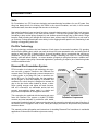
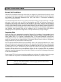
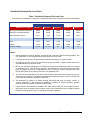
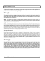
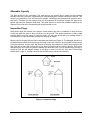
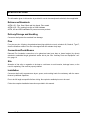
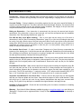
INSTALLATION
MANUAL
Pin Foundations, Inc.
Gig Harbor, Washington
Phone (866) 255-9478/ Fax (253) 858-8607
www.pinfoundations.com or www.diamondpier.com
© 2015 by Pin Foundations, Inc. All rights reserved.
Form # INST1211, Rev. Jan 2015.
Diamond Pier® Foundation Systems are covered by U.S. Patents 5,039,256; 6,910,832; 7,326,003; and
patents pending.
Diamond Pier® is a U.S. registered trademark of Pin Foundations, Inc.
The latest version of this Installation Manual is available on our website, www.diamondpier.com, or by
calling us at 866 255 9478 or 253 858-8809.
Other documents and publications referenced in this manual are listed below and available at
www.diamondpier.com.
National Evaluations
“Diamond Pier DP-50 Precast Concrete Pier Foundation Assembly,” ICC-ES Evaluation Report No.
ESR-1895.
State Evaluations
“Diamond Pier DP-50 Precast Concrete Pier Foundation Assembly,” Wisconsin Building Product
Evaluation, Code Approval No. 201008-O, July 26, 2011.
Test Reports
“Precast Concrete Pier Foundation Assembly Test Report; In Accordance with ICC-ES AC336,”
Professional Service Industries, Inc., PSI Report No. 704-25035-1, November 28, 2006.
“Cross Pin Group Foundation Load Test Report,” Earth Engineers, Inc., EEI Report No. 07-020-8,
January 21, 2013.
Observational Evidence
“Diamond Pier National Performance Submittals,” 2005.
“Diamond Pier Frost Performance Report, Zone II, Minnesota Soils,” 2010.
“Diamond Pier Observational Evidence, Forest Lake, Minnesota,” May 2011.
Building Code Compliance Documents
“Code Compliance Information for Diamond Pier Foundations in the State of Minnesota,” Pin
Foundations, Inc., September 2013.
CONTENTS
INTRODUCTION .......................................................................................................................................... 4
Soils .......................................................................................................................................................... 4
Pin Pile Technology .................................................................................................................................. 4
Diamond Pier Foundation System ............................................................................................................ 4
CONDITIONS AND USES ........................................................................................................................... 5
Normal Soil Conditions ............................................................................................................................. 5
Supporting Soils .................................................................................................................................... 5
Residential Diamond Pier Load Chart................................................................................................... 6
Frost Heave .............................................................................................................................................. 7
Heave Resistance ..................................................................................................................................... 7
INSTALLATION INSTRUCTIONS ............................................................................................................... 8
Preinstallation ........................................................................................................................................... 8
Product Warranty .................................................................................................................................. 8
Inspect for Underground Obstacles ...................................................................................................... 8
Locate Buried Utilities............................................................................................................................ 8
Check Your Layout ................................................................................................................................ 9
Assemble Tools and Supplies ............................................................................................................. 10
Installation ............................................................................................................................................... 10
Identify and Mark Location .................................................................................................................. 10
Set the Concrete Head ........................................................................................................................ 10
Drive in the Pins .................................................................................................................................. 11
Place Inspection Caps on Pins ........................................................................................................... 13
Register Your Product Warranty............................................................................................................. 13
AUXILIARY PARTS AND EQUIPMENT .................................................................................................... 14
Post/Beam Brackets ............................................................................................................................... 14
Breaker Hammers and Driving Bits ........................................................................................................ 14
FIELD INSPECTION .................................................................................................................................. 15
Pin Length ............................................................................................................................................... 15
Pin Specifications ................................................................................................................................... 15
Pier Integrity ............................................................................................................................................ 15
Allowable Capacity ................................................................................................................................. 16
Inspection Plugs...................................................................................................................................... 16
SPECIFICATIONS ..................................................................................................................................... 17
References/Standards ............................................................................................................................ 17
Delivery/Storage and Handling ............................................................................................................... 17
Pins ......................................................................................................................................................... 17
Connections/Posts/Beams ..................................................................................................................... 17
Site .......................................................................................................................................................... 17
Installation ............................................................................................................................................... 17
TROUBLESHOOTING ............................................................................................................................... 18
Diamond Pier® Installation Manual
3
INTRODUCTION
Soils
Pin Foundations, Inc. (PFI) has been designing and manufacturing foundations for over 25 years. One
thing has always driven our thinking—the Earth is the actual foundation, and soils, in their natural
undisturbed state, have the strength and structure to do the job.
Man-made foundations have two basic functions: to transfer loads properly into the Earth’s soil structure
and to provide a connection to the built structure above. There are two general types of man-made
foundations: deep vertical pilings (banged in) and shallow spread footings (dug in and buried). Pilings
keep the Earth’s existing soil strength and structure intact, and are easy to install if they do not need to
go too deep. Footings spread loads more widely, but the digging breaks apart the soil, weakening it and
blocking or exaggerating water flow.
Pin Pile Technology
Pin pile technology combines the best features of both types of man-made foundations. By grouping
short stiff piles (bearing pins), which can easily be driven into intact penetrable soils, and setting them at
angles to work more like a shallow footing, a sound foundation can be constructed that requires no
excavation. The pin pile group simulates nature’s design, resembling the roots of a tree providing
bearing, uplift and lateral capacity . In recent decades, grouped pin piling has become a reliable technology for complex, heavy-duty commercial applications, performing a superior job of transferring loads
to intact undisturbed soils.
Diamond Pier Foundation System
PFI’s innovation is to bring pin pile technology into common use with a superior connector—the Diamond Pier
concrete head. This high-strength, precast component is
a driving guide, a pin piling lock, and a structural connection all in one. As a driving guide, the pier maintains
the pin angles so that their capacity is definable and
consistent. As a lock, the pier is designed to increase its
grip on the pin cluster when loaded up, down, or sideways—getting stronger and tighter as loads increase.
And as a connection, an embedded anchor bolt and
precast, post-matching shape make it a simple and
proportional complement to its supported structure.
Anchor
bolt
Concrete
pier head
Inspection
cap
Bearing
pin
Inspection
plug
This composite pier combined with the bearing pin group
Figure 1. Diamond Pier
forms the Diamond Pier system—a hybrid of familiar
Foundation Components
concrete and steel materials. It provides a solid, stable,
economical foundation that both captures and preserves the supporting strength and natural functions of
the Earth’s soil it's engaged in and, in turn, solidly and simply connects to and protects the permanent
structures above.
This manual provides information and instructions for installing Diamond Pier foundations in residential
applications in Normal Soil Conditions (see next section).
4
Diamond Pier® Installation Manual
CONDITIONS AND USES
Normal Soil Conditions
Diamond Pier foundations sold through retail outlets are designed for projects that are founded in normal
sound soils. Normal soils are typical in most residential neighborhoods throughout the United States and
are defined in the International Residential Code (IRC) Table R401.4.1. Presumptive Load-Bearing
Values of Foundation Materials.
For residential applications the two most common prescriptive bearing soil types relied upon in the IRC
table, and in most local codes, are 2000 psf sands/gravels and 1500 psf silts/clays. Diamond Pier
foundations sold through retail outlets must be founded in soils with a minimum 1500 psf bearing
strength. Supporting soils that do not meet the presumptive bearing strength defined in the applicable
code for your area will not provide expected foundation capacity, and their bearing capacity may need to
be determined by a soils investigation. Ask your local code official for soil information regarding your
site. Additional soils information may also be available at the U.S. Geological Soils Survey website
managed by the U.S. Department of Agriculture—see http://websoilsurvey.sc.egov.usda.gov/.
Supporting Soils
Some soils may not be appropriate for supporting Diamond Pier foundations. Some examples include
soils that are weaker than 1500 psf, soils that are highly expansive, shifting or sliding soils, soils on
slopes greater than 2:1 (27 degrees), contaminated soils, or soils where traditional concrete piers,
accepted by local codes, are unable to provide adequate bearing to support the loads of the project or to
protect the structure from the negative effects of frost heave. Where unsound soils exist, a registered
design professional may be required to review the project.
Soils can also be weakened when they retain standing water or are improperly drained, and in certain
types of soil this can also cause heave problems. A site depression with standing water or the potential
for water to pond, pool, or saturate the soil may be an indication that the soil is not sound. Downspouts
that discharge at or near a foundation may also cause soil problems, and setting the Diamond Pier
foundation system adjacent to or near drainage ditches, creeks, or ponds should be considered
carefully. Soils adjacent to existing foundations may also have been improperly or loosely backfilled,
which may cause poor drainage or poor soil conditions. Check your local code for drainage requirements
in and around foundations. .
Please contact PFI if you have any questions regarding your project or soil conditions, and/or the proper
use of the Diamond Pier product or "Residential Diamond Pier Load Chart," provided in Table 1.
WARNING: You must check for underground utilities and follow the instructions described
under the “Locate Buried Utilities” subsection (page 8) before Diamond Pier
foundations can be installed.
Diamond Pier® Installation Manual
5
Residential Diamond Pier Load Chart
Table 1. Residential Diamond Pier Load Chart
Equivalency to a traditional concrete pier is indicated by Base Area Comparison and Frost Zone Rating.
DP-50 ESR-1895 Code Compliant
Model & Pin Length >
DP-50 36”
DP-50 42”
DP-50 50”
DP-75 50”
DP-75 63”
3600#
3600#
3600#
5150#
5850#
2700#
2700#
2700#
3870#
4400#
Equivalent Bearing Area
1.8 sf
1.8 sf
1.8 sf
2.58 sf
2.93 sf
Base Area Comparison
18” cylinder
18” cylinder
18” cylinder
21” cylinder
23” cylinder
Uplift
670#
920#
1175#
1215#
1380#
Lateral
575#
820#
1070#
1150#
1310#
12"–24”
30"–42”
48”
48”
60”
Bearing in 2000 psf Sands/Gravels
Bearing in 1500 psf Silts/Clays
Frost Zone Rating
1
1
Notes:
1. Values applicable in properly drained, sound soils with a minimum 1500 psf bearing capacity. See
IRC Table R401.4.1 for complete bearing soils listing and Table notes.
2. For simple structures only. No asymmetrical, rotational, overturning, or dynamic loads.
3. All capacities use four pins of the specified length per foundation. Length includes that portion
embedded within the foundation head.
4. DP-50 uses defined in paragraph 2.0 of ESR-1895 and per blue-bordered box above are limited
to residential decks, covered decks, stairways, and walkways. For DP-50 uses beyond these
types of projects, and for DP-75 applications, refer to Cross Pin Group Foundation Load Test
Report (EEI Report No. 07-020-8). See Note 1 for applicable soils.
5.
50” Pins are recommended for use with the DP-50 where uplift and/or lateral loads may govern.
The DP-50 comes with a 1/2” diameter embedded galvanized anchor bolt. The DP-75 comes with
a 5/8” diameter embedded galvanized anchor bolt.
6. The Diamond Pier system is a shallow bearing technology that does not require “refusal” or
“friction” resistance, or the professional installation monitoring or special inspection typically
associated with conventional vertical or battered piling.
7. Larger Diamond Pier models are available—DP-100E and DP-200E. For these larger pier sizes,
site-specific soils information and foundation loads must be determined by a registered design
professional and provided to PFI for calculated foundation capacities.
6
Diamond Pier® Installation Manual
Diamond Pier foundations provide equal or better performance to traditional concrete foundations
claimed as equivalent. In the "Residential Diamond Pier Load Chart" (Table 1), a “base area
comparison” and “frost zone rating” are defined. These two ratings define the size of the traditional
concrete pier foundation that a given Diamond Pier foundation is equivalent to in bearing capacity and
frost heave resistance. For example, a DP-50 with 50" bearing pins shows a base area comparison of
18” and a frost zone rating of 48”. This compares with a traditional 18” round, 48” deep poured concrete
foundation.
To determine whether the Diamond Pier system can be used for a specific project, a registered design
professional may review the Residential Diamond Pier Load Chart and supporting documentation, and
specify the use of the systems with site-specific requirements or caveats in a submittal to your local code
official. Alternatively, PFI may provide a stamped capacity sheet for the Diamond Pier model and pin
length appropriate to the job when site-specific soils and loading information is provided. Contact PFI for
these specific requirements as well as the typical time frame and fees for this type of review.
Frost Heave
Frost is not an unusual or unsound soil condition unless the site has a history of locally accepted
conventional foundations failing due to frost heave or freeze/thaw cycling. In frost zones, a properly
drained, sound soil will freeze solid and hold its foundations tight. In heaving areas, water sources, the
rate of temperature drop, and certain soil grain sizes can combine to cause pressures on foundations in
all directions. The most important of these three factors is the presence of water in the soil, and this
makes proper drainage a must—for all types of foundations.
Heave Resistance
Most traditional concrete foundations in frost zones rely on depth and gross weight as protections
against frost heave. They use significant volumes of site-poured concrete, which has the potential for
many field condition variables and inconsistent mix designs, and their installation requires considerable
excavation, which weakens the existing soil structure, invites water problems, and leaves substantial
amounts of soil to be removed from a site.
Rather than reaching a specific vertical depth or gross weight, Diamond Pier systems resist heave
pressures with their wide-spreading pin pile groups. Embedded in the intact soil structure, the pins are
prevented from changing angle under load by the concrete head, creating a stable foundation for both
bearing and uplift forces. Because of the unique design of the Diamond Pier head, the pins are also free
to move along their axes without compromising the position of the pier or its lock on the pin cluster. This
feature allows the Diamond Pier foundation to absorb soil strains caused by frost heave or expansive
conditions without losing alignment or transferring these strains to the supported structure.
When assessing projects in extreme frost areas, be aware of sites where traditional concrete footings—
48” to 60” deep—have failed to resist frost heave, requiring larger, deeper concrete piers. Project sites
that require concrete footings deeper than 60” to resist frost heave exceed the definition of normal soil
conditions and the limits of the "Residential Diamond Pier Load Chart."
Diamond Pier® Installation Manual
7
INSTALLATION INSTRUCTIONS
These instructions only cover the installation of Diamond Pier foundations in residential applications at
sites where normal soil conditions exist (see discussion of "Normal Soil Conditions" on page 5).
Please also view the Installation Video provided on our website, www.diamondpier.com.
Preinstallation
Product Warranty
Register your product warranty. Go to www.diamondpier.com and click on "Backyards" to view warranty
information and download the Limited Lifetime Warranty Application Form.
Inspect for Underground Obstacles
The same obstacles that conventional foundation systems encounter, such as rocks, tree roots,
underground utility lines, and other buried objects, can also obstruct the Diamond Pier system. Refer to
the “Encountering Obstructions” subsection (page 12) for instructions on handling buried obstacles. If an
obstacle is encountered that cannot be passed using the breaker hammer while driving the pins and not
cracking the pier head in the process, the pins can be removed and the concrete head rotated, allowing
the pins to penetrate the soil in a different location.
Locate Buried Utilities
WARNING: Do not install Diamond Pier foundations before all underground utilities have
been located, marked, and de-energized.
All underground utility lines must be located and properly marked by your local official utility locating
service, and all privately run lines must also be identified and located by the proper authority. If there are
any electrical lines in the area, de-energize the power source prior to installing the Diamond Pier foundations. Never allow bodily contact with uninsulated portions of the automatic breaker hammer. Wear
properly rated rubber-insulated gloves and boots. In, addition, if underground utilities are located on the
site, check with your local utility locating service to confirm required safety zones. You must ensure that
the horizontal pin distance for your foundation will have adequate horizontal clearance to be well outside
all safety zones (see Figure 2 and Table 2 on next page).
8
Diamond Pier® Installation Manual
DP
Safety
Zone
Limit Plane
Utility
Safety Zone
Horizontal Pin
Distance
Buried
Utilities
Figure 2. Horizontal Pin Distance
After installation, horizontal distance of all pins must be well outside all safety zones.
Table 2. Horizontal Pin Distance for All Diamond Pier Models
Measured from center of pier anchor bolt horizontally to vertical limit of pin end.
Horizontal Pin Distance (inches)
Pin Length
(inches)
When Pin Is at 90 degrees
(Perpendicular to Limit Plane)
When Pin Is at 45 degrees
(Shortest Distance to Limit Plane)
36
20
15
42
24
17
50
29
21
63
38
27
84
51
36
126
78
56
Check Your Layout
To meet the load bearing capacities shown in the “Residential Diamond Pier Load Chart” (Table 1, page
6), Diamond Pier foundations must be spaced a minimum of 3 feet apart (from center of pier anchor bolt
to center of pier anchor bolt). If they are spaced less than 3 feet apart, the bearing capacity must be
reduced by 13% for each closer-spaced pier. The piers must also be set back the correct horizontal
distance from existing foundations or other buried obstacles, as shown in Table 2. Tributary loads from
the supported structure must be properly calculated, and the piers spaced accordingly, so that each pier
is supporting only up to its designated allowable loads.
Diamond Pier® Installation Manual
9
Assemble Tools and Supplies
Inspect your Diamond Pier assemblies to ensure that no parts are flawed or have been damaged in
shipping. Do not install a concrete pier if it is a structural crack with a fissure running internally into the
pier (see "Pier Integrity" on page 15). Slight flaking or chipping is acceptable; a pier with surface flaking
or chipping may be installed.
Verify that you have the correct number of concrete pier heads with the corresponding number of
bearing pins (4 per pier), inspection caps (4 per pier), and inspection plugs (4 per pier), and that the
anchor nuts thread properly on the pier anchor bolts.
You will need to assemble the following tools and gear:
•
•
•
•
•
•
•
Automatic driving hammer with 1-1/8” hex shaft driving bit (see "Breaker Hammers and Driving
Bits," page 14)
Square-edge shovel
Sledgehammer
Torpedo level
Tape measure
Pipe wrench
Proper safety goggles, ear protection, insulated gloves, protective clothing, and boots
We recommend a minimum two-person crew for installation.
Installation
Identify and Mark Location
1. Locate where you would like the center of the pier anchor bolt to be.
2. Mark the location by using reference points that will easily identify the center location of the pier
even after top soil is removed.
3. We recommend you set a string line centered on the anchor bolt or with a consistent offset from
the bolt or post bracket to maintain alignment.
Set the Concrete Head
1. Dig a tapered square hole the same size and
shape as the bottom half of the concrete head (see
Figure 3). This creates a cradle to steady the pier
for leveling. Soils directly below the pier should be
left loose.
2. Following safe lifting procedures, carefully lift the
concrete head and position it in the hole to its
midpoint.* Ensure top is level and centered on your
alignment.
3. Replace some of the removed soils back around
the sides of the pier at grade, lightly tamping to
maintain level and alignment during pin driving.
(See Notes under “Drive in the Pins” on page 11.)
Figure 3. Tapered Hole for
Concrete Head
*The pier may also be buried deeper for aesthetic considerations only. Access to the top of the pier needs
to be maintained. Be sure to keep top half of pier clean until caps are applied. The pier MAY NOT be
buried for structural purposes, or cast in a concrete slab. If a slab or patio pavers are intended, an
expansion joint 1” larger than the widest cross section of the pier at its midpoint and encircling the entire
pier must be provided, and proper drainage must be maintained.
10
Diamond Pier® Installation Manual
Drive in the Pins
WARNING: Verify locations of any buried utilities before driving pins (see “Locate Buried
Utilities,” page 8).
1. Remove any dirt and debris from the pins and
check that they will fit easily into the driving holes
in the concrete heads. (If a cut or burr is restricting
the fit, try the other end of the pin.)
2. Install the inspection plugs in the ends of the pins
that will go into the pier first.
3. Slide the pins through opposing holes in the concrete head, making sure to support them so their
weight doesn’t roll the pier out of the hole or out of
alignment.
4. Keeping the pin centered in the driving hole, carefully set pin 6” to 12” into the soil tapping with the
sledgehammer (gripped just below the hammer
Figure 4. Setting Pins and
head) until the pier is locked into a level position
Leveling Pier
(see Figure 4). Impact the pin end squarely to
minimize flaking of the concrete surface or deformation of the end of the pin (see Note 1).
5. With the pin driving bit installed on the automatic hammer, and another crew member holding the
pin, drive in opposing pins alternately in increments. Periodically check for alignment and level (a
5-degree tolerance is allowed). Be sure to keep the weight of the auto-hammer from forcing the
pin against the lower half of the driving hole and impacting the pier. Another crew member
should hold the pin centered in the driving hole (see Figure 5). This will also reduce pin vibration
and minimize concrete flaking.
NOTE: Do not use the pin driving bit as a hammering tool or hammer against it with the
sledgehammer. It is to be used with the automatic hammer only.
6. Temporarily drive all pins down to within 6” from
the top of the pier; this allows easier removal if an
obstruction is encountered.
7. Finish driving the pins with the automatic hammer
(with pin driving bit), being careful not to damage
the precast pier or the upper ends of the pins and
leaving approximately 3/4" of the pin protruding
from the top of the concrete.
Note 1: Do not attempt to drive the pins all the way
down with just a sledgehammer; this may damage the
ends of the pins or crack the pier.
Note 2: Do not drive a pin all the way down at once if
this causes the pier to be pulled to one side. Continue
to rotate around the pier, driving the pins in increments, until the growing strength in the pile group is
sufficient to allow final driving.
Figure 5. Driving Pins with
Note 3: Do not continue to hammer away at a pin that
Auto-hammer and Pin Driving Bit
is bouncing, rattling, or scraping against an impassable
object. This may cause the pier to ride up the pin, push the pier to one side, or risk eccentrically
stressing the pier with a pin that is out of line. It could also cause the pier to have a structural crack,
which would require removal and replacement (see "Pier Integrity" on page 15). If encountering
difficulties in the soil, see “Encountering Obstructions” on the next page.
Diamond Pier® Installation Manual
11
Encountering Obstructions
If a pin stops moving when being driven in, STOP driving the pin. Be sure the other pins are at least
half way in to stabilize the pier and ensure that the pier will remain in place before trying to drive the
obstructed pin in any further. Attempt to drive the obstructed pin with the automatic hammer for
approximately 10 to 20 seconds, or give it one or two firm square hits with the sledgehammer, which
may drive it past the obstruction. If you can remove the pin, you may also try removing the soil plug
and redriving. Inspection plugs may only be omitted when approved by the building official. With the
plug removed and less surface area at the lower end, the pin may drive easier, and not be forced by
the angle of the plug past an obstruction, but off its trajectory. Many small rocks will roll, potentially
allowing the pin to move directly past. If the pin begins to move, continue with the automatic
hammer, but make sure that it is not being forced out of line. If its trajectory is off, this can cause an
eccentric stress on the pier and crack it.
If the trajectory is off or the pin will not go in at all, remove all the pins (see “Removing Pins”), rotate
the pier around its center alignment, and reinstall to avoid the obstruction. The pier may also be
relocated, within the parameters of your structural design, if necessary to avoid underground objects.
If the obstruction is close enough to the surface, it may be dug up and removed. Once accomplished, recompact the soils with the sledgehammer, and then reset the pier.
NOTE: The edges of the top of the concrete pier do not have to align exactly with the sides of the
post or post bracket as long as the bracket being used is fully supported by the concrete and
providing proper weight distribution.
Removing Pins
The jacking method is the easiest way to remove pins. This method works best when the pin is
approximately 6” extended out from the pier. A pipe wrench, a flat bar, and a pry bar are required.
Follow the instructions below to turn the pin while corkscrewing it upward. See also the Pin Removal
video on the website.
1. Using your right hand, place the pry bar flat
against the concrete angle at the outer edge of
the pier and perpendicular to the pin to be
removed.
2. With your left hand, place the pipe wrench on
the pin and slide it down tight to the pry bar. The
pipe wrench handle should be pointing up
slightly and perpendicular to the pry bar to allow
the pipe wrench to turn the pin as it is pried (see
Figure 6).
3. Pull up on the pipe wrench handle to lock.
4. Pull up on the pry bar with your right hand to
move the pin out approximately 1” to 2”.
5. Slide the pry bar back to be flush with the
concrete angle on the pier.
6. Repeat lock and jack (steps 5–7) until the pin
can be pulled by hand.
Figure 6. Jacking Method for
Pin Removal
Note 1: For the first 4” of removal use the flat bar with the pipe wrench. After the pin is 4” removed
you may use a pin as a pry bar.
Note 2: For an alternate removal technique, an internal pipe locking tool with an electric impact
wrench may be used to spin the pin and draw it from the pier.
12
Diamond Pier® Installation Manual
Place Inspection Caps on Pins
1. Set the inspection caps loosely on the ends of the
pins so they can be removed for pin length inspection (see “Field Inspection,” page 15).
2. Set brackets and posts or beams, and frame and
complete the supported structure.
3. Once these framing material loads have been applied, pull the caps off and reverify the extent of the
protruding pins, adjusting as necessary by tapping
with the small sledgehammer.
4. After the field inspection has been completed, tap
the caps down tight with the small hammer (see
Figure 7) to seal them against the concrete.
Figure 7. Completed Installation
with Inspection Caps
Register Your Product Warranty
1. Download Limited Lifetime Warranty Application Form by going to www.diamondpier.com and
clicking on "Backyards".
2. Submit application within 30 days of project completion.
3. Confirm receipt of your registered warranty by PFI.
Diamond Pier® Installation Manual
13
AUXILIARY PARTS AND EQUIPMENT
Post/Beam Brackets
The bracket needed to make the connection from the Diamond Pier foundation to the superstructure can
be purchased separately from a local lumberyard. The DP-50 pier typically has a 1/2" diameter
galvanized bolt embedded in the top of the pier (nut provided), and this bolt will connect to a Simpson
Strong-Tie® bracket (Model ABW) or a similar approved post base. The DP-75 pier has a 5/8" diameter
bolt at the top of the pier; this corresponds to the Simpson Strong-Tie ABU bracket or similar codeapproved post base. Check your local building code or building official to verify which post bases are
acceptable in your area, and make sure to match the post size and loads on the post with the
appropriate bracket size and bracket load ratings. Typically these brackets come with a "standoff" design
that separates the wood from contact with the base of the bracket and eliminates the need to drill into
the bottom of the lumber to compensate for the raised anchor bolt. Most post-base brackets have a wide
hole in the base that allows for horizontal adjustment of the final bracket location.
Horizontal beams may also be set directly in an appropriate bracket for direct connection to the Diamond
Pier foundation when constructing low-profile structures. Larger piers not shown on the "Residential
Diamond Pier Load Chart" (Table 1) have a variety of bolt diameters and configurations. Contact PFI for
more information if your project requires piers larger than the DP-50 or DP-75.
The proper bracket coating or finish should be chosen based on the lumber to be used and the treating
specifications of the project superstructure. If stainless steel is chosen, the embedded galvanized bolt
must be protected from contact with the stainless bracket with the addition of a plastic or rubber bushing
(not supplied) or the piers must be special ordered with embedded stainless steel anchor bolts to avoid
the potential for corrosion of dissimilar metals in contact.
Breaker Hammers and Driving Bits
Only automatic breaker hammers should be used to install the Diamond Pier pins. Any automatic
hammer that will handle a 1-1/8” hex shaft can be used, provided it can be properly and safely controlled
by the operator and not risk injury or damage to the pier. The Diamond Pier driving bit is recommended
for use with the breaker hammer. The driving bit has a 1-1/8" hex shaft, and can be rented or purchased
through a local dealer or purchased directly from PFI.
NOTE: The bits are NOT to be used with, or as, a sledgehammer.
Below is a list of commonly available electric automatic breaker hammers that have a range of impact
energies from 20 to 44 ft-lb. Soft or loose soils will allow for the use of lighter lower-energy hammers.
Stiff or dense soils will require electric hammers in the higher impact range or standard jackhammers
driven by compressed air. In most cases, the DP-50 and DP-75 are installed with electric hammers.
Roto-hammers are not adequate.
•
•
•
•
14
MAKITA Model #HM1307CB 1-1/8” Hex 35-lb Demolition Hammer; Bit type: 1-1/8" Hex
HITACHI Model #H65SD2 1-1/8" Hex 40-lb Demolition Hammer; Bit type: 1-1/8" Hex
BOSCH Model #11335K Jack 15 Amp Breaker Hammer; Bit type: 1-1/8" Hex
MILWAUKEE Model 5338 Breaker Hammer; Bit type: 1-1/8" Hex
Diamond Pier® Installation Manual
FIELD INSPECTION
A Diamond Pier foundation code inspection may take place at any time during or after installation and
may be combined with the structural framing inspection as each jurisdiction warrants. The top ends of all
pins should be accessible for measuring pin lengths.
Pin Length
Diamond pier foundations are designed to be inspected from above grade after they have been installed.
An inspection plug must be installed at the lower (driven) end of the pin to keep soils from moving up
inside it and to allow a tape measure to be slid down from the top of the installed pin to verify its length
(see “Inspection Plugs” on page 16).
NOTE: The Diamond Pier system is a shallow bearing technology and does not require “refusal” or
“friction” resistance, or the professional installation monitoring or special inspection typically associated
with conventional vertical or battered piling.
NOTE: If framing members will be too close to the top of the pier to allow the tape measure to be
inserted, then the inspection should be done before the framing is in place. Also, if inspection plugs have
been unintentionally forgotten, then the pins can be twisted or jacked out with a pipe wrench to verify
their length (see “Removing Pins” on page 12). They can then be redriven into the same soil cavity. If a
plug has been removed to facilitate driving in an obstructed condition (see "Encountering Obstructions,"
page 12), be sure to note or mark the location of this pin for the inspector. Pins are to be their full
specified length without joints or coupling (length tolerance is ±1/2”).
Pin Specifications
Bearing pins provided with the piers are schedule 40 galvanized pipe, Grade A electric resistance
welded, with no threads. This also can be verified from above grade; with the rubber cap removed, the
weld can be verified on the inside wall of the pin, and the wall thickness can be checked. If the wall
thickness is thinner than specified, the pins have been substituted with a lower schedule pipe or conduit
and must be replaced with the properly specified pipe—1” nominal schedule 40 pipe has a wall
thickness of 0.133” (just over 1/8”), 1-1/4” nominal schedule 40 pipe has a wall thickness of 0.140”. The
wall thickness tolerance is ±12%.
Pier Integrity
If the Installation Instructions are properly followed, the piers should be level, and they should not have
structural cracks as a result of improper handling or pin driving. (Surface spalls or chips may occur
during driving or handling, but these are not structural, and will not affect the pier.) A structural crack is a
fissure running internally into the pier. It is perpendicular to the outer face of the pier and heads inward
to the pier core. This can weaken the pier strength and/or allow water to penetrate and cause
freeze/thaw problems in the concrete. If a pier is more than 5 degrees out of level, the symmetry of the
pin pairs may be compromised, and the pier should be removed and correctly reinstalled. If a pier has a
structural crack, it should NOT be patched. It must be removed and replaced.
Diamond Pier® Installation Manual
15
Allowable Capacity
The piers should not be overloaded. The total load on any specific pier is based on the individual
tributary loads of the structure, supported by the corresponding post or beam connected to the pier. This
weight is a combination of the live load (snow, people, furnishings) and the dead load (weight of structure itself). Therefore the total tributary load can be expressed in pounds per square foot (psf) as the
area X total load (live load plus dead load). This value should not exceed the published capacity of the
Diamond Pier model and corresponding pin length intended for use.
Inspection Plugs
Hard plastic plugs are inserted in the bottom of each bearing pin prior to installation to keep soil from
moving up inside the pins as they are driven into the ground. This allows inspectors to slide a tape
measure down a pin from above to verify its length. You may also check with your building official or
local inspector for other acceptable methods for verifying pin length.
Align the slot in the plug with the interior weld bead and insert (see Figure 8). The allowable tolerance in
pin wall thickness means that some plugs will fit high in the end of the pin, and some will fit down almost
to the plug shoulder. In either case, tap the point of the plug with a hammer to seat it firmly enough in the
end of the pin so that it will not drop out as you slide it through the driving holes in the pier. Don’t worry
that tapping the end of the plug with the hammer will blunt the point; it is not intended as a piercing or
cutting tip, and this will happen anyway as the plug is driven into the soil. (See see "Encountering
Obstructions," page 12, for plug use where buried obstructions may be encountered.)
Figure 8. Inspection Plugs
16
Diamond Pier® Installation Manual
SPECIFICATIONS
The information given in this section is provided for use in document/permit submittal, where applicable.
References/Standards
ASTM A 53 - Pipe, Steel, Black and Hot dipped, Zinc-coated
ASTM A153 - Zinc coating (hot-dip) on Steel Hardware
ASTM, ACI and CRSI standards for precast concrete products
Delivery/Storage and Handling
Contractor shall protect the materials from damage.
Pins
Four pins per pier. All pins to be galvanized steel pipe with butt cut ends, schedule 40, Grade A, Type E,
electric resistance welded. Pins are to be capped with UV-resistant vinyl caps.
Connections/Posts/Beams
Diamond Pier foundation connection to be galvanized steel post base or beam bracket (by others)
attached to embedded single galvanized anchor bolt in pier. See “Auxiliary Parts and Equipment” section, page 14.
Site
Alteration of site soils or vegetation to be kept to a minimum to avoid erosion, drainage issues, or the
need for replanting. Site must be properly drained.
Installation
Contractor shall verify superstructure layout, spans, and resulting loads for consistency with the manufacturer’s published capacities.
Pins to be full length as specified before driving. No coupled or welded pins are to be used.
Follow the complete Installation Instructions provided in this manual.
Diamond Pier® Installation Manual
17
TROUBLESHOOTING
Cracked Pier – Always inspect materials when received from supplier. Do not install a pier that has a
structural crack or fissure running internally into the pier. Slight flaking or chipping does not constitute a
crack.
Concrete Flaking – During installation, pins rubbing against the pier may cause superficial flaking of
concrete around the driving hole. This will not affect the structural strength. However, if a structural crack
or fissure running internally into the pier develops during installation, the integrity of the pier has been
compromised and the pier must be removed and replaced.
Hitting an Obstruction – If an obstruction is encountered, the pins may be removed and the pier
repositioned. If the obstruction is dug out and removed, soil must be recompacted per the Installation
Instructions. See “Encountering Obstructions” (page 12).
Pier Will Not Stay Level When Installing – One or more pins may be driving out of line due to
obstructions in the soil (See “Encountering Obstructions,” page 12), or your hole for setting the pier may
be too big. Only dig a hole the size of the pier being used, and be sure to put all pins in the pier before
setting them. With all the pins sticking up from the pier, one person can also push or pull on the pins to
manipulate the leveling process and guide or steer the pier to a level position, being careful not to
wrench on the pier and cause a crack.
Pier Installed Out of Level – If a pier is more than 5 degrees out of level, this may compromise the
symmetry of the bearing pins—it should be removed and repositioned. Reinstall the pins incrementally at
first, checking level constantly, and if one pin is not going in straight and is causing the pier to tip, install
the other pins first and then carefully finish driving this last pin.
Pins Have Risen Slightly Out of the Concrete Head – This may occur when extreme loads have been
applied to the pier, but the system is designed to relieve pressure in this way. The pins may simply be
tapped back to their original position with a small hammer. Remove the caps, tap the pin, and replace
the caps.
Pins Will Not Fit into Pier – Make sure the pins fit into the pier before inserting the inspection plugs. Be
sure pins and piers are free of dirt, and check both ends for fit. Always transport and store parts in a
clean environment. Measure the pin diameter to be sure the proper pins have been supplied for your
pier model. (The DP-50 model has a 1" nominal pin with a 1.315" actual outside diameter [OD]; DP-75
has a 1-1/4" nominal pin with a 1.67" actual OD.) If the pins still do not fit, contact your supplier.
Inspection Caps Will Not Fit over Driven Pins – Check to be sure the proper cap size was supplied
and that your caps are pliable and not frozen. Caps should be tapped on with a small hammer. If they
still will not go on, check the pin ends for any extreme deformations that may have occurred while
driving. File or grind off any damage to re-establish the original diameter, and apply the cap.
Installing in Frozen Ground – Check with the local building code for criteria or limitations on installing
foundations in frozen soil.
Warranty – See Limited Lifetime Warranty available by going to www.diamondpier.com and clicking on
"Backyards". Projects must be registered within 30 days of Diamond Pier installation for the warranty to
be in effect.
18
Diamond Pier® Installation Manual