1
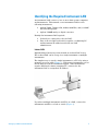
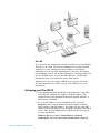
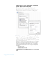
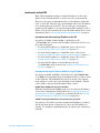
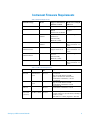
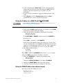
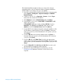
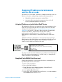
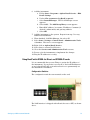
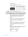
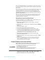
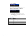
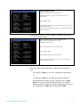
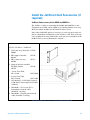
Setting up a LAN Instrument Network Installation Guide Notices © Agilent Technologies, Inc. 2010 Warranty No part of this manual may be reproduced in any form or by any means (including electronic storage and retrieval or translation into a foreign language) without prior agreement and written consent from Agilent Technologies, Inc. as governed by United States and international copyright laws. The material contained in this document is provided “as is,” and is subject to being changed, without notice, in future editions. Further, to the maximum extent permitted by applicable law, Agilent disclaims all warranties, either express or implied, with regard to this manual and any information contained herein, including but not limited to the implied warranties of merchant-ability and fitness for a particular purpose. Agilent shall not be liable for errors or for incidental or consequential damages in connection with the furnishing, use, or performance of this document or of any information contained herein. Should Agilent and the user have a separate written agreement with warranty terms covering the material in this document that conflict with these terms, the warranty terms in the separate agreement shall control. Manual Part Number G2070-90605 Edition Revision 1.0 June 2010 Printed in USA Agilent Technologies, Inc. 2850 Centerville Road Wilmington, DE 19808-1610 USA Technology Licenses The hardware and/or software described in this document are furnished under a license and may be used or copied only in accordance with such license. Restricted Rights Legend If software is for use in the performance of a U.S. Government prime contract or subcontract, Software is delivered and licensed as "Commercial computer software" as defined in DFAR 252.227-7014 (June 1995), or as a "commercial item" as defined in FAR 2.101(a) or as "Restricted computer software" as defined in FAR 52.227-19 (June 1987) or any equivalent agency regulation or contract clause. Use, duplication or disclosure of Software is subject to Agilent Technologies’ standard commercial license terms, and non-DOD Departments and Agencies of the U.S. Government will receive no greater than Restricted Rights as defined in FAR 52.22719(c)(1-2) (June 1987). U.S. Government users will receive no greater than Limited Rights as defined in FAR 52.227-14 (June 1987) or DFAR 252.227-7015 (b)(2) (November 1995), as applicable in any technical data. Contents Identifying the Required Instrument LAN ...........................................5 Configuring your PC for TCP/IP .................................................................... 6 Instruments on the LAN ................................................................................. 8 Instrument Firmware Requirements ...................................................9 Setting IP addresses from instrument keypad ...................................10 Setting the IP address for a 7890A GC ......................................................... 10 Setting the IP address for a 6890N GC ........................................................ 10 Setting the IP address for a 6850 GC with SN≥US102430001 ................. 11 Setting the 7820A IP Address from software keypad ............................... 11 Assigning IP addresses to instruments with Jet Direct cards ........13 Assigning IP addresses using the Agilent BootP Service ........................ 13 Using BootP with J2552A/B Jet Direct card ............................................. 13 Using BootP with J4100A Jet Direct and G1369A/B cards..................... 14 Assigning IP addresses permanently with Telnet ..................................... 16 Verify communications using the ping command..............................19 Install the Jet Direct Card Accessories (if required) ........................20 Chemstation LAN Installation Checklist .............................................22 Setting up a LAN Instrument Network 3 Setting up a LAN Instrument Network 4 Identifying the Required Instrument LAN An instrument LAN consists of one or more data system computers and instruments. This manual covers instrument LANs for the following instruments: • Agilent 7890A, 7820A, 6850, 6890A, 6890 Plus, and/or 6890N Gas Chromatographs • Agilent 35900E analog to digital converter Identify the instrument LAN required: • Isolated (not connected to the site LAN). • Part of the site LAN itself, which requires coordinating PC and instrument IP addresses with the site LAN administrator. Isolated LAN Implementing a laboratory network with an isolated LAN is easy. The isolated LAN can be set up for a single instrument or multiple instruments. The simplest way to attach a single instrument to a PC is by using a network crossover cable (Figure 1). With newer instruments you set the IP address from the instrument keypad. Older instruments require additional software running a PC connected to the instrument LAN to assign their IP address. Figure 1: Simple hookup to a network If you have multiple instruments and PCs on a LAN, connect the instruments and PCs to a hub or switch (Figure 2). Setting up a LAN Instrument Network 5 Figure 2: Network multiple instruments on a LAN Site LAN You can attach the workstation and all of the laboratory instruments directly to a site LAN. The LAN site administrator assigns fixed IP addresses for each instrument you are adding to the network. Depending on your site LAN administrator’s direction, PCs added for instrument control can obtain LAN addresses automatically from the site’s DHCP server, or have fixed IP addresses. All PCs and instruments they control must be on the same subnet. Agilent Service does not support DHCP for its systems. Have the site LAN administrator reserve a group of IP addresses for your instruments. Configuring your PC for TCP/IP 1. If not already installed, install the network interface card (NIC) in the PC and configure the adapter’s TCP/IP address. The Agilent Technologies bundled Chemstation System will have a LAN interface installed. 2. To set the IP address on your ChemStation PC, select the Properties tab for the instrument network adapter. Isolated LANs require a fixed IP address. Site LANs can use a fixed IP address, but the IP addresses are normally assigned by the DHCP server. The site LAN administrator will decide the best option for your installation. Windows XP: Select Start > Control Panel > Network Connections. Then select Local Area Connection > General. Setting up a LAN Instrument Network 6 Windows Vista: Select Start > Control Panel > Network and Sharing > Manage Network Connections. Windows 7: Select Start > Control Panel > Network and Sharing Center. Then select Local Area Connection > Properties. From the Local Area Connection Properties screen highlight Internet Protocol version 4 and select Properties. Figure 3: Set the IP Address on PC 3. If the PC is set to use the site’s DHCP server to assign IP address, select “Obtain an IP address automatically” and select “Obtain DNS server address automatically”. If the PC is using a fixed IP address, enter the IP Address, Subnet Mask, and Default Gateway for the PC. On a site LAN, this information is provided by the site LAN administrator. If the PC is configured as an isolated LAN, local or non-routable IP addresses are used. For an isolated network, the first three numbers in all IP addresses must be the same – i.e., 10.1.1.X, where X must be in the range 1 to 255. A typical configuration would be: PC IP address: 10.1.1.100 Instrument 1 IP address: 10.1.1.101 Instrument 2 IP address: 10.1.1.102 A default gateway is not needed for the PC if it is on an isolated LAN. Setting up a LAN Instrument Network 7 Instruments on the LAN Each LAN instrument requires a unique IP address on the same subnet as the ChemStation PC to work correctly on the network. There are two types of instruments that can be added to either the local or site LAN. The first type of instrument allows the IP address to be entered directly at the GC. The second type of instrument requires the IP address to be assigned using either Agilent BootP or Telnet. For specific information on the IP addressing mode for your instrument refer to Instrument Firmware Requirements on page 9. Instruments that allow entering IP address at the GC If you have a 7890A, 7820A, 6890N, or 6850 Series (SN ≥ US10243001) GC you enter the IP address directly at the GC or at the software keypad. • To enter the IP address to a 7890A GC refer to the section Setting the IP address for a 7890A GC on page 10). • To enter the IP address to a 7820A GC refer to the section Setting the 7820A IP Address from software keypad on page 11). • To enter the IP address to a 6890N GC refer to the section Setting the IP address for a 6890N GC on page 10). • To enter the IP address to the 6850 Series GC (SN ≥ US10243001) refer to the section Setting the IP address for a 6850 GC on page 11). Instruments that require Telnet or BootP to assign IP address If you have a 6890A, 6890 Plus, 6850 Series GC (SN≤US00003200), or 35900E your instrument uses an installed Jet Direct card to work on the network. The 6890 LAN kit (G2335A) needs to be ordered from Agilent if a card cage is not installed on the 6890 GC. The kit comes with a card cage and G1369A Jet Direct Card. G1369A/B and J4100A cards that stores IP address With the G1369A/B and J4100A cards you can enter the IP address for the above instruments using Telnet (See Assigning IP addresses permanently with Telnet on page 16) or Agilent BootP (See Storing Settings Permanently with Bootp Program on page 16). J2552A/B card requires BootP to be running when power cycling GC If you have a J2552A/B card, after setting the IP address, you must run BootP when power cycling the GC, since the LAN address is volatile. It is highly recommended that you replace this card with a G1369B. Setting up a LAN Instrument Network 8 Instrument Firmware Requirements Table 1: Instrument Requirements Instrument Type Model Supported instrument firmware revision Method for setting IP addresses 7890A G3440A A.01.10.3 Set at GC keypad 7820A G4350A 7820A.01.10.013.1.bin (E,C,J) 7820A.01.10.013.Ru.bin Set using software keypad 6890N GC G1530N/ G1540N N.06.07 for 7693A And N.05.06 LAN Assembly Firmware 04.7B3 Set at GC keypad 6890 Plus, 6890A G1530A/ G1540A A.03.08 Chip Set Determined by Jet Direct card used – see below. 6850 Series GC SN≤US00003200 G2630A A.03.07 for 7693A support and A.03.03 Determined by Jet Direct card used – see below. 6850 Series GC SN≥US10243001 G2630A A.06.02 for 7693A and A.05.04 LAN Assembly Firmware 04.7B3 Set at GC keypad 35900E 35900E E.01.02 Determined by Jet Direct card used – see below. Product Table 2: Jet Direct Card Requirements Minimum Hardware Support Statements Rev G1369B LAN Interface card B.01.01 G1369A LAN Interface card C.03.00 J4100A Jet Direct Card K.08.32 J2552A/B (obsolete) Jet Direct Card A.08.32 Setting up a LAN Instrument Network 10/100BaseT Supported with GC and 35900E Replaces the G1369A card mid 2010 Set IP address with Telnet or BootP 10/100BaseT Supported with GC and 35900E Set IP address with Telnet or BootP 10/100 Base T Set IP address with Telnet or BootP 10 Base T only Needs BootP Service (BootP must be running if the GC is cycled) LAN address is volatile (Upgrade to G1369B) 9 Setting IP addresses from instrument keypad When entering an IP address at an instrument, be sure it is correct and is not in use by another device (such as a printer). Setting the IP address for a 7890A GC 1. Pr ess [Options]. Scr oll to Communications and pr ess [Enter]. Scroll to Enable DHCP and, if necessary, press [Off/No] to disable DHCP. When prompted, turn the GC off and then on again. 2. Press [Options]. Scroll to Communications and press [Enter]. 3. Scroll to IP. Enter the numbers of the GC IP address, separated by dots, and press [Enter]. A message tells you to power cycle the instrument. Do not power cycle yet. Press [Clear]. 4. Scroll to GW. Enter the Gateway number and press [Enter]. A message tells you to power cycle the instrument. Do not power cycle yet. Press [Clear]. 5. Scroll to SM and press [Mode/Type]. Scroll to the appropriate subnet mask from the list given and press [Enter]. A message tells you to power cycle the instrument. Do not power cycle yet. Press [Clear]. 6. Scroll to Reboot GC and press [Enter] to power cycle the instrument and apply the LAN setpoints. Setting the IP address for a 6890N GC NOTE For Agilent 6890A or 6890 Plus GCs refer to the instructions in the section Assigning IP addresses permanently with Telnet on page 16. 1. On the 6890N keypad, press [Options]. Scroll to Communication and press [Enter]. The following screen appears: COMMUNICATION SETPTS ---- LAN ---IP: 000.000.000.000 < GW: 000.000.000.000 SM: 000.000.000.000 Enable DHCP OFF ---- RS-232 ---- 2. Enter the IP address for your 6890N GC. Enter the numbers separated by dots and press [Enter]. The GC displays a message instructing you to power cycle the instrument. Do not power cycle yet. Press [Clear]. 3. Scroll to GW. Enter the Gateway number and press [Enter]. The GC displays a message instructing you to power cycle the instrument. Do not power cycle yet. Press [Clear]. Setting up a LAN Instrument Network 10 4. Scroll to SM and press [Mode/Type]. Scroll to the appropriate subnet mask from the list of modes and press [Enter]. The GC displays a message instructing you to power cycle the instrument. 5. Power cycle the instrument to apply the LAN setpoints to the card. 6. Press [Options]. Scroll to Communications and press [Enter]. Confirm that the correct setpoints are present. Setting the IP address for a 6850 GC with SN≥US102430001 NOTE For Agilent 6850 (SN≤US00003200*) GCs refer to the instructions in the section Assigning IP addresses permanently with Telnet on page 16. 1. Turn the GC off. 2. Press and hold LOAD and turn the GC on. Continue to hold LOAD until five dots appear in the GC display. 3. When the GC finishes initializing, the display should read: DHCP mode or IP Address DISABLED XXX.XXX.XXX If the DHCP MODE is ENABLED, change the mode to DISABLED by pressing ▲ or ▼. Press LOAD to continue to the IP ADDRESS. If the GC does not display either of the above two screens, your GC uses card J2552B or card J4100A and firmware that does not support local IP addressing. If this is the case, either update the firmware or use Agilent Bootp service to set the IP address. 4. The display will now read: IP ADDRESS XXX.XXX.XXX Press LOAD to adjust the IP ADDRESS values. Press ▲ or ▼ to change values and LOAD to move from one value to the next. 5. When the IP ADDRESS is completed, the display reads: DEFAULT GATEWAY XXX.XXX.XXX.XXX Change the DEFAULT GATEWAY as you did the IP ADDRESS. 6. Change the SUBNET MASK value in the same manner. 7. Cycle the GC power for the new settings to take effect. Setting the 7820A IP Address from software keypad From the factory, the 7820A GC is set to: IP address 192.168.0.26 Subnet Mask 255.255.255.0 Gateway 192.168.0.1 Setting up a LAN Instrument Network 11 The initial installation r equir es that you connect the software keypad dir ectly to the GC using this address. During installation this IP address can change or be set to use DHCP. 1. Start the software keyboard. From the Windows® Start program menu, Agilent > All Programs > Agilent Technologies > 7820A GC Remote Controller. 2. Connect to the GC. Go to Connection > Connect…. In the Target field, enter the current GC IP address 3. Click [Options]. Scroll to Communications and click [Enter]. 4. Verify DHCP is off. Scroll to Enable DHCP. If Enable DHCP is Off, skip to the next step. If Enable DHCP is On, turn it off by clicking [Off/No]. Scroll to Reboot GC. Click [On/Yes] and [On/Yes]. After reboot, click [Options]. Scroll to Communications and click [Enter]. 5. Scroll to IP. Use the numeric keypad to enter the numbers of the GC IP address, separated by dots, and click [Enter]. A message tells you to power cycle the instrument. Do not power cycle yet. Click [Clear]. 6. Scroll to GW. Enter the Gateway number and click [Enter]. A message tells you to power cycle the instrument. Do not power cycle yet. Click [Clear]. 7. Scroll to SM and click [Mode/Type]. Scroll to the appropriate subnet mask from the list given and click [Enter]. A message tells you to power cycle the instrument. Do not power cycle yet. Click [Clear]. 8. Scroll to Reboot GC. Click [On/Yes] and [On/Yes] to power cycle the instrument and apply the LAN setpoints. 9. Ping the GC using the IP address entered above. See the Troubleshooting manual for details or if the GC does not respond. Setting up a LAN Instrument Network 12 Assigning IP addresses to instruments with Jet Direct cards IP addresses for the 6890A, 6890 Plus, 35900E, and 6850A with a Jet Direct card can be configured by using the following methods: • Manually setting the parameters using Telnet. • Automatically requesting the parameters from a BootP Server (using the Agilent BootP Service). Assigning IP addresses using the Agilent BootP Service The Agilent BootP Service is required to attach an instrument to the LAN only if you are using the J2552 Jet Direct Card. For all other Jet Direct Cards, Telnet (See Assigning IP addresses permanently with Telnet on page 16) is the most direct method to permanently assign an IP address. Alternatively BootP can be used to permanently assign IP addresses to a Jet Direct card while maintaining a central listing of all fixed IP addresses used in the subnet. Agilent BootP Service maintains an association between a unique identification code (MAC address) provided with the LAN card and the specific IP address assigned to that instrument. The MAC address can be found on a label on the card. Part number of the LAN interface Revision Code, Vendor, Year and Week of assembly MAC address Country of origin Figure 4: MAC label You must set this association whenever you add a new instrument to the LAN, replace an instrument (or its LAN card), or change the IP address assigned to an instrument. Using BootP with J2552A/B Jet Direct card Change the parameters of the G2552A Jet Direct card using Bootp by following the instructions below: 1. Turn off the instrument. 2. Record the MAC address. 3. From Windows, select Start > Settings > Control Panel > Administrative Tools > Services. 4. Select Agilent BootP Service. 5. Select Stop. After stopping the BootP service, close the Services and Administrative Tools screen. Setting up a LAN Instrument Network 13 6. Add the instrument a. Follow Start > Programs > Agilent BootP Service > Edit BootP Settings b. Uncheck Do you want to log BootP requests? c. Select Launch Manager. The BootP Manager screen appears. d. Select Add… The Add Bootp Entry screen appears. e. Enter MAC address, host name, IP address, Comment (if desired), subnet mask, and gateway address. f. Select OK. 7. Add the instrument to the system. Repeat from step 5 for any additional instruments. 8. When finished, click Exit Manager, the select OK. 9. Select Start > Settings > Control Panel > Administrative Tools > Services. The service screen appears. 10. Right-click on Agilent BootP Service. 11. Select Start to restart BootP Service. 12. Close the Services and Administrative Tools screens. 13. Power cycle the instruments to implement the changes. 14. Ping the IP addresses to verify. Using BootP with J4100A Jet Direct and G1369A/B cards It is recommended that you use Telnet to assign the IP address of the instrument. If you prefer to use BootP to track all IP addresses on an isolated LAN, this section describes how to permanently set the instrument’s IP address. Configuration Switches The configuration switches are mounted on the card. Figure 5 Location of Configuration Switches The LAN interface is shipped with all switches set to OFF, as shown above. Setting up a LAN Instrument Network 14 Initialization Mode Selection The following initialization modes are selectable: NOTE Compared to the G1369A LAN card, SW 7 and SW 8 must always be in OFF position on the G1369B LAN card, otherwise the selected modes are not working. Bootp When the initialization mode “Bootp” is selected, the card tries to download the parameters from a Bootp Server. The parameters obtained become the active parameters immediately. They are not stored to the non-volatile memory of the card. Therefore, the parameters are lost with the next power cycle of the card. Bootp & Store When “Bootp & Store” is selected, the parameters obtained from a Bootp Server become the active parameters immediately. In addition, they are stored to the non-volatile memory of the card. After a power cycle the parameters are still available. Using Stored When initialization mode “Using Stored” is selected, the parameters are taken from the non-volatile memory of the card. The TCP/IP connection will be established using these parameters. The parameters were configured previously by one of the methods described below. Using Default When “Using Default” is selected, the factory default parameters are taken instead. These parameters enable a TCP/IP connection to the LAN Interface without further configuration. Setting up a LAN Instrument Network 15 Since the default IP address is a local address, it will not be routed by any network device. Thus, the PC and the card must reside in the same subnet. The user may open a Telnet session using the default IP address and change the parameters stored in the non-volatile memory of the card. He may then close the session, select the initialization mode “Using Stored”, power-on again and establish the TCP/IP connection using the new parameters. When the card is wired to the PC directly, separated from the local area network, the user may simply keep the default parameters to establish the TCP/IP connection. Storing Settings Permanently with Bootp Program Change the parameters of the J4100A Jet Direct and 1369A/B card using Bootp by following the instructions below: 1. Turn off the instrument that hosts the Jet Direct card and remove the card. 2. Change the card’s settings of the Configuration Switch to”Bootp & Store” mode. 3. Install the Jet Direct card. 4. Start the Bootp program and open its window. 5. If required, modify the parameters for the Jet Direct card. 6. Now turn on the instrument with the Jet Direct card and view the Bootp program window. The parameters are now stored permanently in the non-volatile memory of the card. 7. Close the Bootp program and turn off the instrument and remove the Jet Direct card. 8. Change the settings of the card’s Configuration Switch to “Using Stored” mode. 9. Install the card and power cycle the instrument with the Jet Direct card. The instrument can be accessed now via LAN without the Bootp Server program. Assigning IP addresses permanently with Telnet The IP address can be set by opening a Telnet session for any Jet Direct card except the J2552A/B card (BootP required). NOTE If using Windows Vista or Windows 7 you need to enable the Telnet client. 1. Go to Start Menu and select Control Panel. 2. Click on Programs in Control Panel. 3. Click on “Turn Windows Features On or Off” under Programs and Features. 4. Scroll down in displayed list and check Telnet Client and click on OK . 1. Open the system (DOS) prompt window by clicking on Windows START button and select “Run...”. Type “cmd” and press OK. 2. Type the following at the system (DOS) prompt: Setting up a LAN Instrument Network 16 Figure 6: Telnet command where <IP address> is a nonroutable unique local address that you assign or a routable address assigned by the site LAN manager. When the connection was established successfully, the card responds with the following: Figure 7: Telnet result 3. To set the IP address, subnet mask, and gateway enter the command <ipaddress> for each instrument. The value of the command is shown in the table below. For example: ip 134.40.24.230 Press [Enter] after each command. Table 3: Telnet Commands Command Description ? Displays syntax and descriptions of commands / Displays current settings ip <address> Sets new ip address sn <address> Sets new subnet mask gw <address> Sets new default gateway Quit Saves changes and exit shell Exit Exits shell without saving changes 4. Use the “/” and press Enter to list the current settings. Setting up a LAN Instrument Network 17 Information about the card Product id, firmware revision s, MAC address Initialization mode is Bootp. The connected PC/Bootserver is 134.40.30.184 Active TCP/IP settings Stored TCP/IP settings in non-volatile memory (not visible if equal to active TCP/IP settings) Connected to PC with controller software (e.g. Agilent ChemStation), here not connected Figure 8: Telnet information 5. Change the IP address (in this example 134.40.24.230) and type “/” to list current settings. Enter ip 130.40.24.158 [Enter]. Changes the TCP/IP setting. Enter / [Enter]. It then displays these settings: Initialization mode is Bootp The connected PC/Bootserver is 134.40.30.184 Active TCP/IP settings Stored TCP/IP settings in non-volatile memory Last user change IP 134.40.24.150 (not active yet, requires mode “Using Stored” and re-start) Figure 9: Change the IP address 6. When you have finished typing the configuration parameters, type: quit and press [Enter] to store the configuration parameters or exit and press [Enter] to exit without storing parameters. If the Initialization Mode Switch is changed now to “Using Stored” mode, the instrument will take the stored settings when the module is re-booted. In the example above it would be 134.40.24.158 on QUIT and 134.40.24.160 on EXIT. Setting up a LAN Instrument Network 18 Verify communications using the ping command The ping command verifies communications across a TCP/IP connection. Ping does not verify if the subnet mask and gateway are correct. To use it, open the MS-DOS command prompt. Type ping followed by an IP address. For example, if the IP address is 192.168.1.56, enter ping 192.168.1.56. If LAN communications are working properly, you will see a successful reply. For example: Figure 10: Ping Setting up a LAN Instrument Network 19 Install the Jet Direct Card Accessories (if required) JetDirect Card accessory for the 6890A and 6890 Plus The JetDirect card for connecting the 6890A and 6890 Plus to the Chemstation via LAN can be added to an existing 6890 as accessory #G2335A which includes the G1369A Jet Direct Card. Part of the 6890 LAN option/accessory is a card cage and connector that accommodates installation of the JetDirect card. This card cage is not standard on every 6890. If the card cage is not installed on the 6890 GC this accessory kit must be ordered. G2335A Jet Direct - LANCard 1. LAN card assy (G1369A) G136960001 2. MIO support bracket 00320 G1550- 3. MIO connector assy 60100 G1553- 4. Support bracket standoff, M3 male/female G153020570 5. Screw, Torx T-10, M3 × 6 mm 0515-0680 6. Screw, Torx T-20, M4 × 12 mm 0515-2496 7. G1530-61485 – LAN Cable Category 5 100 Base-T twisted pair LAN cable (8 Meter) 8. 5023-0203 – Cross-over (PC to instrument) network cable (shielded, 3 m long) 9. 5023-0202 – Twisted pair network cable (shielded, 7 m long) Table 4: The G2335A Jet Direct Accessory Kit for the 6890A and 6890 Plus GC Setting up a LAN Instrument Network 20 JetDirect Card connection of the 6850 and 35900E to the Chemstation The Jet Direct Accessory Kit for the 6850 and 35900E (G1369A) consists of: • G1369-60001 – JetDirect Card • G1369-90000 - Manual • G1530-61485 – LAN Cable Category 5 100 Base-T twisted pair LAN cable (8 Meter) • 5023-0203 – Cross-over (PC to instrument) network cable (shielded, 3 m long) • 5023-0202 – Twisted pair network cable (shielded, 7 m long) Install the JetDirect Card in the MIO slot in the back of the instrument. The card cage is standard in every 6850 GC and 35900E A/D. Setting up a LAN Instrument Network 21 Chemstation LAN Installation Checklist Determine configuration – Isolated or Site LAN. Determine Instrument and PC IP addresses, Network Subnet Mask and Gateway. For each instrument and each PC with a fixed IP address record the IP address, subnet Mask, and default gateway. Install the Network Interface Card (if necessary). Install TCP/IP on the PC. Configure TCP/IP with IP Address/Subnet Mask/Gateway. Gateway is required only for Site LAN installation. If required, install the JetDirect cards in 6850/6890 GC’s and 35900E A/D’s. Connect LAN cables from the PC to instruments. Use a crossover cable for single instrument installation on an isolated LAN, and HUB/LAN cables for multi-instrument installation. Install the Chemstation Software and required Instrument Modules. If required, install the BootP Service from the Chemstation Software CD. If required, use Telnet or BootP to add entries for each instrument to be installed. Run the Chemstation Configuration Editor and setup each instrument for IP address. Startup each Chemstation instrument session to confirm operation. Setting up a LAN Instrument Network 22 Edition G2070-90605 Revision 1 ©Agilent Techologies, Inc. Printed in USA, June 2010