1
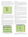
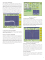
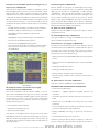
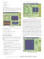
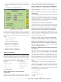
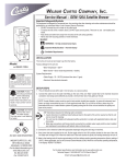
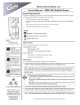
Wireless 3920B Series Analog and Digital Radio Test Platform Featuring Improved RF Signal Generator Phase Noise Performance Introducing the 3920B, the latest radio test solution from Aeroflex for engineering, production and field service applications. The 3920B features an improvement to the RF signal generator phase noise specification of -110 dBc/Hz at 10 kHz offset. The instrument provides a comprehensive range of general purpose analog measurement facilities as well as advanced digital test options. The 3920B includes many standard features as well as a host of optional test capabilities and digital personalities. The 3920B standard features include: • 1 GHz frequency range •High performance FM/AM/SSB analog duplex test capabilities •Sensitive receiver with built-in pre-amp for off air measurements The 3920B also includes many optional features including: •2.7 GHz frequency range extension • Harmonics and spurious measurements • Tracking generator •Audio spectrum analyzer and audio tracking generator (used for analog simulcast alignment) • IQ generator for use with IQCreator® • P25 conventional operation with advanced parametric/protocol analysis • P25 trunking operation • LSM generate and receive analysis • P25 Phase II TDMA physical layer transmitter and receiver testing • Off Air Monitor for P25 message logging – protocol analysis tool • Color coded pass/fail results • P25 AES encryption •-140 dBm (typical) DANL spectrum analyzer with 8 markers •SmartZoneTM and SMARTNETTM trunking • Dual-Channel oscilloscope to 4 MHz • TETRA mobile, base station and DMO tests •Full audio analysis for AF level, frequency, SINAD and distortion measurements • HPD (High Performance Data) base and mobile simulation •Three high accuracy audio modulators/function generators • Three high accuracy audio baseband generators •Tone encode and decode functionality including DTMF, DCS, tone remote, 2-tone sequential, and 5/6-tone • DMR (MOTOTRBOTM) mobile and repeater tests •NXDNTM, dPMR and ARIB STD T98 Automatic test and alignment options include: • Motorola ASTRO®, ASTRO® 25 and APX™ Series radios • EF Johnson ES and VP600 Series radios • BK DPHX5102X and KNG Series radios • TIA/EIA-603 FM land mobile radio test software • GPIB, Ethernet, USB and RS-232 interfaces • MOTOTRBO radios • HP/Agilent 8920B remote emulation • Harris P7300, P5500 and XG-75 Series • Kenwood P25 TK-5X10, 5X20 and NXDN Series radios • DMR Repeaters For the very latest specifications visit www.aeroflex.com The one test set for all your narrowbanding test needs! High Performance With the largest selection of digital radio options of any radio test set, the 3920B will meet all of your narrowbanding test needs, both now and in the future. The software defined digital architecture of the 3920B provides for future technology enhancements as new digital technology becomes available. You can easily perform software updates in the field, making additions of new software features and options as simple as plugging in a USB flash memory drive. Measurement speed is directly related to processing power and internal communications. The 3920B digital architecture utilizes a mixture of powerful digital signal processors and programmable logic. Coupled to the use of a compact PCI backplane capable of delivering peak rates of >100 MB, this ensures that the instrument has the power to acquire, synchronize and process data, producing measurement results to the user with the minimum of delay. Accurate Testing Time Base: With a 0.01 ppm OCXO frequency standard, the 3920B provides ultra-reliable RF frequency measurements. For even more stability, the 3920B provides an external frequency reference input. Generator: Level accuracy is important in determining today’s receiver performance in design, manufacturing and field service environments. With a 1 dB (0.6 dB typical) level accuracy on the RF output ports, the 3920B provides consistent results in testing receiver parameters. Menu of Radio Test Systems in the 3920B Ease of Use Combining the power of an onboard PC with a 30 GB hard-drive and Linux OS, the 3920B can support USB mouse and keyboard interface for very easy operation as well as almost unlimited save/recall setups, saving time and effort. Multiple methods of controlling the 3920B include the front panel keys, using a mouse and keyboard, or through a VNC application on your PC, touch-screen tablet or mobile phone. Ease of Test To make you more productive, the 3920B is not only simple to use but has features that makes testing a radio quick and repeatable. The 3920B features easy-to-read meters with Pass/Fail color coding for instant Go/NoGo testing. With these easy-to-configure meters, you can set up unique Pass/Fail parameters for each radio type that you are testing. When used with the save/recall locations, this allows for instant recall of the test parameters, so semi-technical or non-technical individuals can simply key the radio and test. The meters will display “Green” for good, “Red” for high and “Blue” for low. A quick glance and the operator will know that the radio is within established test parameters. Receiver: For sensitive measurement, e.g. off-air analysis, a low power input is provided via the antenna input port. This low level input gives the user the ability to measure an off the air signal as low as -100 dBm or -115 dBm with the internal pre-amp selected. Direct input of signal power of up to 125 W is supported, making the 3920B compatible with virtually all practical requirements for mobile terminal and base station test. Audio: With high accuracy audio generators from 1 mV to 8 V rms, the 3920B provides level accuracy to ±1% of the setting. The audio generator frequency ranges from 20 Hz to 40 kHz and 0.1 Hz resolution provides solid audio performance for audio testing. The AF Counter features full range from 20 Hz to 20 kHz. Automatic Testing The Auto-Test II environment provides you with the capability to turn the 3920B into a stand alone ATE test environment. With the built-in PC running your test script, or one of our available automatic test and alignment applications, the 3920B can be conformed to your exact testing needs. Available with the Auto-Test II option for the 3920B are a selection of applications covering many of the latest digital radios. With these applications, you can automatically test and align the transmitter/receiver of a radio in as little as 5 minutes. Motorola ASTRO 25 Radio Alignment P25 UUT Measurements Tile Maximized, Showing Green, Red and Blue Indications More automatic test and alignment options are being added all the time. For the latest selection of scripts for the 3920B, go to www.aeroflex.com/3920 and click on the 3920 Radio Test Set Scripts link in the Product Directory. 2 3920B Standard Features FM/AM/SSB Analog Duplex operation: The 3920B features advanced RF testing capabilities for FM/AM/SSB radio transmitters and receivers. The features for analog duplex testing are: • 1 GHz frequency range for transmitter and receiver (2.7 GHz optional) • Three Modulation sources • Three Audio sources • DTMF encode and decode • DCS encode and decode • 2-tone sequential and tone remote encode and decode •Tone sequential encode operation that includes up to 40 tones, user defined pause, tone frequency shift, all standard tone sequential codes and two USER defined sequential codes •Tone sequential decode that can decode according to standard tone protocols or according to user defined tone protocol •Channel analyzer that can simultaneous display the RF spectrum while demodulating received signal •Meters for measuring RF Power, Modulation, Frequency Offset, Distortion, Audio level, SINAD, SNR, and Hum and Noise • Dual Channel 4 MHz Oscilloscope Spectrum Analyzer Digital Multimeter: Now standard for the 3920B is the Digital Multimeter. The Digital Multimeter comes with three new ports on the front panel used for measuring AC/DC volts, AC/DC amps and OHMS. Remote Control: The 3920B supports remote control via GPIB for automated test system control. A VXI pnp VISA driver allows easy test system integration of the 3920B. In addition to a native 3920B command set, the 3920B also supports commands for the HP/Agilent 8920B that allows migration from the 8920B to the 3920B extremely easy. Remote Operation: Use of the 3920B Ethernet connection permits remote operation from anywhere in the world making it possible to download new software or remotely interrogate instrument status. With an internal VNC server, users can install VNC software on their PC or Tablet PC and remotely operate the front panel of the 3920B from virtually anywhere on the planet. All that is needed is the ability to access the unit’s IP address. Optional Test Capabilities Site Monitoring Application (390XOPT051) Analog Duplex Screen Full span spectrum analyzer: View signals from 1 MHz to 1 GHz with the 3920B or to a full 2.7 GHz with the frequency extended option. With a DANL of -140 dBm (300 Hz RBW with pre-amp enabled), the 3920B provides high performance spectrum analysis. This full band analyzer provides plenty of range to view harmonics and other spurious emissions in and out of band. The 3920B brings impressive new capabilities to site monitoring applications. With option 392XOPT051, the user now has the ability to leave the 3920B on-site while the unit provides automated data logging of the site’s effective receiver sensitivity. When connected to a good documented receiver (a “golden” radio), the 3920B will automatically calculate the Effective Receiver Sensitivity (ERS) at a predetermined interval (example: every 10 seconds) over a specified time (example: log ERS for 72 hours). As these measurements are taken, a min/average/max SINAD is displayed, and the data is logged to the 3920B’s internal hard-drive. Spectral information is also optionally logged with each measurement to help locate and track sources of interference. This gives the system engineer a valuable tool in determining site location performance and system RF boundaries. IQ Gen Modulation (390XOPT054) IQCreator is an Aeroflex developed PC based software utility that gives the user the ability to develop their own waveforms to use as the modulation source. Since the waveforms are defined by I and Q, virtually any type of complex digital modulation format can be created. With the IQ Gen Modulation option, once the IQ waveform is created it can easily be uploaded to the 3920B and used as the modulation source in the Analog Duplex System. For the very latest specifications visit www.aeroflex.com 3 Audio Analyzer (390XOPT055) With 390XOPT055, the 3920B provides audio spectral analysis of the recovered audio signal, either from the audio inputs or from the demodulated RF signal. This feature allows users to view frequency amplitude in relation to other audio frequencies and to isolate problems such as noise in audio circuits. With a frequency range of 1 Hz to 24 kHz, the audio analyzer covers more than the full audio frequency range of mobiles and hand-helds. In addition, there are two markers, plus a peak hold and average function. The user can also capture traces that can be stored and then recalled later for use as a comparison with a live trace. A tracking generator option (390XOPT210) is also available as an add-on to the audio analyzer. Harmonics and Spurious Tracking Generator (390XOPT061) A full featured spectrum analyzer is available, standard, on all 3920Bs. Available as an option to the spectrum analyzer, the 3920B tracking generator allows the user to look at the response of a duplexer, filter bank or other RF device on the spectrum analyzer. This option greatly simplifies the often laborious process of checking or changing the tuning of a duplexer. When used with the optional return loss bridge (AC4105), the spectrum analyzer/tracking generator can measure the return loss of an antenna or cable. Audio Analyzer 2.7 GHz Frequency Range (392XOPT058) The 3920B comes standard with a generate and receive frequency range of 10 MHz (100 kHz usable) to 1.05 GHz. This option will extend the range to 2.7 GHz. Harmonics and Spurious (390XOPT060) The ability to quickly and accurately measure the harmonics and spurious of the transmitter of a radio is the function of 390XOPT060. The fundamental frequency is automatically detected and measured and then the second and third harmonics are measured and compared. In addition, the spurious signals that are higher than the configured level are identified and displayed. The frequency and level of the fundamental, as well as the harmonics and spurs, are then displayed. This option makes finding the harmonics and spurious transmitter very simple. Simply connect the transmitter of the radio to the 3920B, key the radio and press Start. Spectrum Analyzer with Tracking Generator Power Between Markers (390XOPT064) Also available as an option, the power between markers option provides a measurement of the amount of power between the spectrum analyzer markers. With this feature, the user can set the position of two markers on the spectrum analyzer and then measure the amount of power in the bandwidth selected with those markers. This will enable the user to determine the amount of power in an adjacent channel or in the center channel. POCSAG (390XOPT067) The user can now test and verify the operation of both POCSAG transmitters and receivers. When this option is enabled, there are two new tiles available from the tile drop down arrows. This adds the following capability: 4 POCSAG Encode • APCO P25 conventional and trunked radios • Send Alphanumeric or Numeric POCSAG formatted pages • APCO P25 Phase II TDMA • Select any rate from 400 to 4800 Hz • SmartZone and SMARTNET • Select deviation from 0 to 50,000 Hz • DMR (Digital Mobile Radio) • Select Normal or Inverted for polarity •NXDN • Pick from a selection of canned messages or create a custom message • HPD (High Performance Data) • Select RIC (Radio Identification Code) of encoded message, or send to a range of RIC’s POCSAG Decode • dPMR (digital Private Mobile Radio) •ARIB T98 (Digital Convenience Radio Equipment For Simplified Service) P25 CONVENTIONAL OPERATION (390XOPT200) • Select Decode Format - either Automatic, Alphanumeric or Numeric • Select Decode Filter - decode all messages or only messages to a user selectable RIC • Select Normal or Inverted Polarity for decoding • Displays deviation and rate of decoded message • Displays the RIC and the type bits (two bits) of the decoded messages as well as the message The 3920B P25 Conventional Option provides test features for testing P25 radios and systems. Featured is the ability to transmit P25 C4FM standard waveforms and analyze P25 received waveforms. The analysis of the received waveforms consists of the ability to perform RF and modulation parametric tests. The vocoder enables the user to perform transmit and receive audio testing. Included in this option is the capability to: • Measure C4FM modulation fidelity and symbol deviation • Measure power, frequency error and TX BER • Measure symbol clock error Chinese GUI (390XOPT090) • Measure RX BER This option enables the selection of either Chinese or English as the language for the graphical user interface for the Analog Duplex system. When enabled, a selection is added to the utilities screen that allows the user to choose between English or Chinese character display in the audio Analog Duplex system. • Display eye diagram of C4FM demodulation • Display constellation plot of C4FM symbols • Display C4FM symbol deviation distribution plot • Transmit full TIA/EIA-102 test patterns (STD1011, CAL, SILENCE, STD511, etc.) as specified by TIA- EIA-102.CAAA-C • Transmit and receive live audio using the vocoder • Transmit stored speech patterns • Decode voice channel header and link control messages • Encode link control messages • Perform DES encryption Illustration of Chinese GUI OPTIONAL SYSTEM PERSONALITIES In addition to the Analog Duplex system, the 3920B can support a number of optional test systems or personalities, installed concurrently. Personalities include: •TETRA digital trunked radio systems for mobile station and base station testing • TETRA direct mode testing For the very latest specifications visit P25 Conventional www.aeroflex.com 5 P25 Trunking Operation VHF/UHF/700/800 MHz (390XOPT201) To further enhance P25 operation, the addition of the P25 trunking option allows simulation of a P25 control channel in any frequency band. Channel plans may be configured to test virtually any P25 trunked system. A simulator tile logs the messages sent by the radio under test and allows the 3920B to simulate a virtual mobile, configured to talk to the radio under test. This option enables the user to originate a group call to the radio under test or make a group call from the radio under test to the 3920B. In addition, the user can have multiple radios register and affiliate with the 3920B and then originate calls from one radio to the other radios. P25 Control Channel Logger Option (390XOPT206) This option provides the user a tool to perform advanced protocol analysis on both control channel and voice channel data. With this option the user can log P25 data by streaming the received data in real time from the Ethernet port to a PC. This data is logged in an XML format so that the user can easily view the data using a text editor or use an external program to perform further analysis on the data. This data can be logged at three different levels ranging from the raw data symbols up through decoded data. The data is time-stamped on a frame by frame basis. In addition to being able to log data, the user can also send data to the 3920B to be transmitted, making the 3920B into a completely user defined data modem for P25. SmartZone and SMARTNET (390XOPT207) This option provides support for Motorola Astro SmartZone and SMARTNET systems, including support for rebanded channels in the 800 MHz band. KVL Keyloader Option (390XOPT209) This option provides an interface to the KVL Keyloader enabling the user to be able to directly enter keys into the 3920B using a KVL-3000+. Analog Simulcast Option (390XOPT210) P25 Trunking Simulation LSM Generate and Receive/Analysis (390XOPT204) In addition to the standard P25 modulation, also available on the 3920B is the capability to generate and receive Linear Simulcast Modulation (LSM). This option, available as an extension of P25 conventional operation, enables measurements that are specific to LSM. It also adds a graphical analysis of the demodulated LSM signal that is normally only found in vector signal analyzers. Since LSM is a complex type modulation, this plot shows the inphase versus quadrature phase (I versus Q) of the demodulated LSM signal. In addition, this option adds Error Vector Magnitude to the selection of measurements available from the UUT Measurements tile. This option is actually an extension to the Audio Analyzer option and acts as a tracking generator for the audio analyzer. This feature is designed primarily for use in characterizing the performance of Motorola Analog Simulcast systems and enables detailed alignment of the 0-100 Hz band. In addition, this option allows for extended characterization of audio circuits from 0-10 kHz. Explicit Mode Trunking (390XOPT212) The advanced form of frequency channel assignment known as Explicit Messaging is supported by adding option 390XOPT212 to the P25 Trunking Operation VHF/UHF/700/800 MHz option. The explicit mode of operation assigns the actual channel/frequency over the air by providing the exact TX and RX frequency assignments directly to the radio. Unit to Unit Call (390XOPT213) This option adds capability of testing the unit to unit call functionality of a mobile station to the P25 trunking option. The user can either originate a unit to unit call from the mobile station or from the test set. Adjacent Channel Broadcast Message (390XOPT214) This option adds the adjacent status broadcast message to the control channel messages transmitted by the 3920B. This will enable the user to test the capability of the mobile station to operate correctly in the presence of this message. The purpose of this message is to inform mobile stations of the presence and status of sites adjacent to this particular site. Secondary Control Channel Broadcast Message (390XOPT215) LSM Signal Analysis Screen This option adds the secondary control channel broadcast message to the control channel messages transmitted by the 3920B. This will enable the user to test the capability of the mobile station to operate correctly in the presence of this message. This message is used to inform mobile stations of other control channels or other potential backup control channels at this site. 6 P25 Phase II Two-Slot TDMA (Time Division Multiple Access) Physical Layer (390XOPT220) P25 AES Encryption (390XOPT240) One of the newest features of the 3920B is the capability to test P25 Phase II TDMA operation of both base stations and mobile stations. With this option, the 3920B can measure and analyze the different modulations used for both the outbound and inbound signals used in P25 Phase II. With the modulation for Phase II being completely different from the Phase 1 C4FM modulation; this option is critical for radio technicians, designers, or anyone involved with the roll-out of P25 Phase II systems. Included with this option are the following features: With the addition of this option, the 3920B supports P25 encryption formats and manual key entry for systems that employ DES OFB Type III (included in 390XOPT200) or AES encryption (390XOPT240). These options allow decoding of encrypted voice frames to verify encrypted channel performance. Encryption keys may be loaded manually using either the front panel or external keypad or with option 390XOPT209, keys may be loaded with the Project 25 Key Fill Device (KFD) interface protocol. Additionally, keys may be loaded using KVL ASN mode of operation found in KVL3000 and older model key loaders from Motorola. • H-CPM (inbound modulation) modulation and demodulation X2-TDMA Test Suite (390XOPT219) • H-CPM eye diagram, distribution plot, and constellation Available for testing X2-TDMA test systems, this option is available through Motorola only. •H-DQPSK (outbound modulation) modulation and demodulation X2-TDMA Mobile Emulator (390XOPT245) • H-DQPSK eye diagram, distribution plot, and constellation • Generation of all H-CPM standard patterns This option enables the testing of X2-TDMA base stations. This option is available through Motorola only. • Generation of all H-DQPSK standard patterns P25 Performance Test Triggers (390XOPT260) • U UT measurements for Phase II including modulation fidelity, symbol deviation, symbol clock error, frequency error, power and TX Bit Error In order to perform the P25 Performance Tests required by the TIA 102-CAAA standard, the 3920B has the capability with this option of generating trigger signals. This Sync I/O port on the rear panel of the 3920B is used to source this trigger. The output trigger signal is generated when any of the following occur. •Switching between the STD SILENCE pattern and the STD 1011 pattern •Switching between the STD BUSY pattern and the STD 1DLE pattern •Enabling the STD LDU1 pattern •Enabling the STD LDU2 pattern •During trunking simulation at each slot boundary •During trunking simulation, when a Channel Grant message is transmitted X2-TDMA Advance Test Suite (390XOPT261) This option combines 390XOPT216 and 390XOPT245. P25 Phase II MOTOROLA HPD TESTING OPTION (390XOPT300) Off Air Monitor Software for P25 Message Logging Protocol Analysis Tool (390XOPT230) • Generate/receive HPD signals The Aeroflex 3920B P25 Off Air Monitor (OAM) is used to capture and view APCO P25 messages sent over the air. The OAM can receive and demodulate P25 RF signaling, decode P25 messages and log these messages to a file for later viewing. Both trunked (control and traffic) and conventional channels are supported, allowing network engineers to: • Verify compliance to P25 standards •Transmitter parameters including signal power, frequency error, EVM •Symbol clock error, RX BER, burst timing error and occupied bandwidth •I & Q modulation analysis including constellation and trajectory plots of the data symbols, synch and pilot bits • Troubleshoot existing P25 systems • Analyze third party signaling This option is a PC application that, using the data from option 390XOPT206, performs an advanced decoded display and log of the XML data streams from multiple P25 channels. This provides the user with the data to perform a complete analysis of all channels of a P25 trunked system. For the very latest specifications visit • Modulation - 64QAM, 16QAM and QPSK (inbound and outbound) •Display of Min/Max and average as specified by the number of bursts • Pass/Fail indication using color code meters Aeroflex has developed this test mode for Motorola to address the need for testing their high performance packet data operation on www.aeroflex.com 7 both mobiles and base stations in the 700 and 800 MHz bands. HPD systems operate within the normal 25 kHz mobile radio bandwidth. The 3920B HPD options provide users with the ability to test High Performance Data systems. HPD can be configured for two modes of operation. When configured to operate in BR Mode the test set simulates base radio operation and is used to test the functionality of Motorola HPD Mobile Subscriber Units (MSU). When configured to operate in MSU Mode the test set simulates Mobile Subscriber Unit operation and is used to test the functionality of Motorola Base Repeaters (BR). • Distribution plot of symbol deviation • Eye diagram of FSK demodulation • Power profile of burst and of burst ramp up/ramp down • Transmit and receive live audio using the vocoder • Transmit stored speech patterns • Test duplex or simplex mobiles • Wake-up burst for testing repeaters • Synchronize with repeaters • BER testing • Encode color code and call ID • Decode color code, unit ID and call ID Example of HPD Tiles Motorola HPD Advanced Analysis Package (390XOPT301) More advanced features are available with 390XOPT301 including: •Received Data Stream Logger. Logs the data portion of the HPD signal and displays it in hex. •RX Time Display. Shows frequency error, power and symbol clock error over time. •HPD Magnitude/Phase Estimation. Displays magnitude and phase fluctuations of the received signal. • Eye Diagram and I/Q over time displays • P ower Profile. Shows the power over time and in a burst (TDMA transmission). •Power Ramps. Shows the power up and power down portion of the TDMA burst. Motorola HPD Testing Suite (390XOPT302) This option combines 390XOPT300 and 390XOPT301. DMR (390XOPT400) Add advanced testing capability for DMR (Digital Mobile Radio) with 390XOPT400. This option enables the Aeroflex 3920B Digital Radio Test Set to test and align a wide range of DMR repeaters and mobile stations. DMR radio technology is a digital radio format offering advanced communications features specified by the ETSI technical standard ETSI TS 102-361-1. Capabilities of the 3920B include: • Generate and receive DMR modulated signals Example of DMR Tiles DMR XML Channel Logger Option (390XOPT402) With this option, the user can now capture and log to a file (on a PC connected to the 3920B through a LAN) the raw data that is transmitted by a mobile station or repeater. The data is formatted using XML, so that it can be decoded with an external program (developed by the user) or viewed with a text editor. This is perfect for the engineer doing development work or the test engineer in the field that needs to capture the data being transmitted by a repeater or subscriber unit. The data is captured by connecting a PC to the 3920B through an Ethernet crossover cable. Using the PC application, (available at www.aeroflex.com/3920) “DMR XML channel logger for 3920”, the user can both log DMR XML data and send XML files that can control the data being transmitted by the 3920B. dPMR (390XOPT420) dPMR is an ETSI standard specified in ETSI TS 102 658. This option adds advanced testing capabilities that conform to the requirements of this ETSI standard. The transmitter tests include power, frequency error, FSK error, symbol deviation and symbol clock error. This option also provides several graphical screens that provide more insight into the accuracy of the dPMR modulation. NXDN (390XOPT440) • Measure symbol clock error Add advanced testing capability for NXDN with 390XOPT440. This option enables the Aeroflex 3920B Digital Radio Test Set to perform a variety of Transmitter and Receiver tests on any NXDN radio. Transmitter measurements include: • Measure slot power • Signal power • Measure FSK error and magnitude error • Measure symbol deviation 8 • Frequency error • Option for testing Direct Mode Operation (DMO) • FSK error • Symbol deviation • TX BER • Symbol clock error The system supports both 4800 and 9600 baud systems. The 3920B can also analyze the modulation as an eye diagram, symbol distribution plot and a symbol constellation plot. A power over time graph can be used to diagnose power-related issues. Example of TETRA MS Tiles Example of NXDN Tiles The 3920B NXDN Option supports receiver testing with a variety of signal generation patterns. • STD 1031 (1031 Hz pattern) • STD CAL (1031 Hz pattern with 5% BER) • STD 511 (PN9 bit sequence) • STD INTFR (PN15 bit sequence) ARIB STD T98 (390XOPT460) The option provides testing for mobile stations that conform to the ARIB T98 standard. This testing is similar to dPMR and NXDN. For TETRA applications, the 3920B is the successor to the Aeroflex 2968 TETRA Radio Test Set, the established industry standard for TETRA R&D, manufacturing, application development and service operations. Building upon the experience gained over many years of TETRA test, the 3920B with the TETRA options provides the world’s best solution for testing TETRA radios. TETRA system options provide signaling and physical layer measurement requirements for testing TETRA radio equipment. Measurements are made in accordance with ETSI EN 300 394-1 for on channel transmitter and receiver parameters. Signaling functions support TIP (Tetra Interoperability Profile) compliant TETRA radios, thus ensuring optimum compatibility with TETRA equipment from various suppliers. Whatever the device under test, the TETRA system options have the flexibility to measure the various burst types specified by the TETRA standard including normal bursts, control bursts and synchronization bursts. The 3920B offers high speed measurement capabilities to expedite production testing. As a direct benefit of high power signal processing capacity, TETRA measurements are performed nearly nine times faster than its predecessor. TETRA • Mobile station testing with test signal T1 (390XOPT110) • Base station testing with test signal T1 (390XOPT111) • Generate/analyze TETRA RF signals •Base station and mobile station testing plus testing with test signal T1 •Transmit parameter measurements including power, frequency error, EVM and burst timing • TETRA RF power meter and burst power analysis up to 125 W • Modulation analysis with I/Q constellation and trajectory display •Receiver Bit Error Rate (BER) and Message Error Rate (MER) measurements • Pass/Fail indication using color coded meters • TETRA protocol analyzer/simulator Profile Full Tile Maximized TETRA • Data display mode • Time stamped protocol history For the very latest specifications visit www.aeroflex.com 9 TETRA Test (TT) Protocol Support The TETRA MS option provides support for the TETRA Test (TT) protocol as defined in ETSI EN 300 394-1. The TT protocol allows the mobile to be tested in a loopback mode whereby the mobiles BER, MER and RBER can all be reported. Audio Testing Subjective audio testing is supported for simplex and duplex calls. Audio spoken into the mobile’s microphone is received and stored by the test set, which then re-transmits the speech so that it is replayed through the mobile’s speaker or ear piece with 2 seconds delay added, thus, providing an end-to-end audio quality test. Direct Mode Functionality (390XOPT112) Trajectory Tile Maximized Call Processing Highlights The 3920B can be freely configured to emulate a TETRA network by selection of the appropriate channel plan, country code, network code, color code, etc. Once configured, registration, group attachment and TETRA call types including group call, private call, emergency call, telephone call and user defined call can all be tested. SDS messages (types 1 to 4 and SDS-TL) can be sent or received. The 3920B TETRA system option displays a range of mobile reported information relating to registration, group attachment, test mode, call type, called party, status messages, text messages and DTMF digits dialed. The 3920B also supports the testing of Direct Mode Operation. The 3920B can initiate or receive calls from a mobile that is operating in direct mode and then make transmitter measurements such as power, frequency error and modulation accuracy. The operation and graphical displays are very similar to the normal TETRA operation. TETRA Energy Economy Mode (390XOPT114) This optional mode of operation provides protocol signaling to control a mobile’s energy economy mode from “Stay alive” through energy groups EG1 (shortest sleep) to EG7 (longest sleep) and is used in conjunction with the comprehensive signaling capabilities already within the TETRA MS option. This operation enables developers, operators and users to configure battery test scenarios to simulate particular operational conditions. It gives them the testing flexibility to characterize the expected battery life performance in its intended operational use on the network. TEDS Test Operation (390XOPT117) With the TEDS (TETRA Enhanced Data Service) testing operation, the 3920B has the capability to test TEDS capable mobile stations. The testing is performed by using the TEDS T4 test mode of operation. This enables the 3920B to make transmitter and receive performance measurements. These measurements include: • Power • Burst Timing • RMS and Peak Vector Error • Frequency Error • IQ Imbalance • Bit Error Rate Protocol History Maximized Tile TETRA Test Mode T1 and T1 Loopback The TETRA MS and TETRA BS options provides various T1 test signals as defined in ETSI EN 300 394-1 for performing manual testing of TETRA base station and mobile stations receivers. The test signal T1 in the MS T1 application provides control information to the mobile to aid testing, e.g. burst type, max, TX power, loopback commands. These T1 test signals can be used by the mobile in a test mode to output received demodulated data to a test interface for external processing of receiver Bit Error Rate (BER). Alternatively, the mobile can be commanded by the test signal T1 to loop back the received data to the 3920B which can then perform BER/MER/ PUEM measurement. In the BS T1 application, the 3920B also supports T1 loopback BER/MER/PUEM measurements for base stations. • Message Error Rate The 3920B can also display graphically the modulation error. These graphical displays are: • Constellation • Vector Error • Phase Error • Magnitude Error AUTO-TEST II Available as an option for the 3920B is the Auto-Test II operation. Providing the ultimate in flexibility, this option gives you the ability to control the operation of 3920B using the TCL scripting language. You control the functions of the 3920B through the use of RCI commands, which are sent as part of the TCL program. 10 • Develop your own automated tests for any system in the 3920B •Design your own Graphical User Interface Uses TCL scripting language • Utilizes the full set of 3920B RCI Commands ASTRO XTL-5000, ASTRO XTL-2500, ASTRO XTL-1500 and Astro Spectra Plus. Requires 390XOPT200 and 390XOPT218. Motorola ASTRO Series Auto-Test/Alignment (390XOPT601) Provides the functionality of 390XOPT600 for the following radios: XTS3000, ASTRO Saber, ASTRO Spectra. Requires 390XOPT200 and 390XOPT218. Motorola ASTRO 25 Series XTL Power Auto-Test/Alignment (390XOPT602) Adds the capability for full power alignment of mobiles. Includes all current bias adjustments, power characterization and current limit settings for the XTL-5000, XTL-2500, XTL-1500 and PM1500. Typical alignment time is less than 4 minutes for a full power characterization alignment. Requires 390XOPT200, 390XOPT218, 390XOPT053, AC24011 and 390XOPT600. TIA/EIA-603 FM Land Mobile Test (390XOPT603) This application is self-contained within the 3920B and automatically performs the test functions as prescribed by the EIA/TIA-603 standards for testing any FM Land Mobile Radio. Configure up to 30 channels with independent test customization for each channel. Example of Auto-Test II Display Motorola APX Series Auto-Test/Alignment (390XOPT604) Auto-Test II is also the environment for running the auto alignment options. Auto alignment is available for several manufacturers’ radios, and more are being added all the time. The Auto-Test II Programming Environment is available for all of the systems in the 3920B: • Analog duplex (390XOPT059) This option allows test and alignment of APX Series radios. The application can perform a full alignment on the single or dual band radios. Analog alignments and digital performance tests will ensure the radio has maximum coverage area. EF Johnson ES Series Auto-Test/Alignment (390XOPT606) • P25 radio systems (390XOPT218) This option adds the capability to complete a fully automatic alignment on EF Johnson P25 radios. The option has the same features as option 390XOPT600, but for EF Johnson P25 radios. • HPD radio systems (390XOPT303) BK DPHX5102X Series Auto-Test/Alignment (390XOPT607) • DMR radio systems (390XOPT401) This option adds the capability to complete a fully automatic alignment on BK DPHX5102X radios. • TETRA (390XOPT115) • dPMR radio systems (390XOPT421) Kenwood P25 TK-5X10G Series Radio Auto-Test/Alignment (390XOPT608) • NXDN radio systems (390XOPT441) • ARIB T98 radio systems (390XOPT461) Validate radios faster than ever with ease. Connect the test cables, press “Test and Align” and you are free to do more important things. The Auto-Test/Alignment applications are self-contained within the 3920B and automatically perform the functions of radio alignment and verification to ensure optimal radio performance. These applications can test and align radios in as little as 5 minutes. This package provides support for the following radios: TK-5210G, TK-5310G, TK-5410, TK-5710BG/HBG, TK-5810BG/HBG, TK-5910B. This option adds the capability to perform a fully automatic test and alignment on Kenwood P25 TK-5X10G Series radios. This option includes all the tests and alignments required by the Kenwood P25 TK-5X10G Series radios including power, frequency, mod balance, deviation, squelch, and many others. To insure optimum P25 operation, this application includes P25 performance testing. Alignments Performance Tests MOTOTRBO Series Auto-Test/Alignment (390XOPT610) • Reference oscillator • P25 modulation fidelity • Power • P25 symbol deviation • Deviation balance • P25 RX BER This option adds the capability to complete a fully automatic test and alignment on MOTOTRBO Series radios. This option is compatible with all MOTOTRBO XPR™ Series radios and support for new MOTOTRBO Series radios will be added in the future. This option includes the following tests and alignments: Auto-Test/Alignment • Front End alignment • Rx Front End Filter Motorola ASTRO 25 Series Auto-Test/Alignment (390XOPT600) • Rx Rated Volume This package provides support for the following radios: XTS®5000, XTS2500, XTS1500, XTS4000, MT 1500, PM1500TM, SSE 5000, For the very latest specifications visit • Rx Front End Gain and Atten • Rx BER www.aeroflex.com 11 • Tx Ref Oscillator • Tx Power • Tx Modulation Balance • Tx BER • Tx FSK Error • Tx Magnitude Error • Tx Symbol Deviation Technisonics Type 1 Radio Auto-Test/Alignment (390XOPT614) This option adds the capability to complete a fully automatic test and alignment on Technisonics Type 1 radios. This option provides the same functionality of the ASTRO Series radio Auto-Test/alignment software, but for the Technisonics Type 1 radios. Technisonics Type 2 Radio Auto-Test/Alignment (390XOPT615) This option adds the capability to complete a fully automatic test and alignment on Technisonics Type 2 radios. This option provides the same functionality of the ASTRO 25 Series radio Auto-Test/alignment software, but for the Technisonics Type 2 radios. TX Tests perform the key transmitter and receiver tests for DMR Repeaters. This test does not require the DMR repeater to be in any special test mode, but can quickly make these measurements on any channel programmed into the repeater. The user simply indicates the frequencies that the repeater is using from the auto-test setup screen, and then can initiate the test and walk away. The testing is all performed completely automatically Specification RF Signal Generator FREQUENCY Range 10 MHz to 1.05 GHz (Standard) (Usable from 100 kHz) 10 MHz to 2.7 GHz (392XOPT058) (Usable from 100 kHz) Resolution 1 Hz Accuracy Frequency standard ±1 count OUTPUT LEVEL Range Resolution Accuracy •Frequency T/R Port: -130.0 to -30.0 dBm (-30 dBm max for CW or FM; -35 dBm max for AM modulations; -40 dBm max for complex modulations) Duplex: -130.0 to +10.0 dBm (+10 dBm max for CW or FM; +5 dBm max for AM modulations; 0 dBm max for complex modulation) 0.1 dB 1.0 dB for levels >-110 dBm (Typical better than 0.6 dB) 1.5 dB for levels ≤-110 dBm (Typical better than 1.0 dB) •Power •CTCSS • Microphone sensitivity SPECTRAL PURITY • Modulation limiting Residual FM <5 Hz (300 Hz to 3 kHz bandwidth) • Audio distortion Residual AM <0.1% RMS (300 Hz to 3 kHz bandwidth) • Audio frequency response Harmonics • FM hum and noise <-25 dBc (Typically -30 dBc, RF level set at +10 dBm) Non-Harmonics <-55 dBc (all freq. except Crossovers) RX Tests <-35 dBc (At 2nd order crossover frequency) • Audio distortion (10 MHz to 1 GHz: Crossover = 1400 MHz Gen freq.) • Audio sensitivity (1 GHz to 2.7 GHz: Crossover = 3400 MHz Gen freq.) • Audio frequency response • Usable sensitivity Phase Noise (Tracking Gen: Crossover = 3410.7 MHz Gen freq.) <-110 dBc/Hz @ 10 kHz offset, RF <500 MHz) • Displacement bandwidth <-106 dBc/Hz @ 10 kHz offset, RF ≤1000 MHz) • Audio squelch sensitivity <-95 dBc/Hz @ 10 kHz offset, RF >1000 MHz • Audio squelch blocking • Hum and noise Test High/Low or both power level settings on any channel with support for a PTT line to auto-key/de-key the transmitter. Single channel test execution is allowed to re-check failed channels. Supports re-test, accept failure or abort on any failed test. Supports store and recall for test configurations and test results. Network or local printer support allows for an immediate hard copy to be obtained. DMR Repeater Auto-Test (390XOPT626) With the DMR repeater auto-test, the 3920B can automatically 12 MODULATION RF measurements Selections OFF, AM, FM, FM50us, FM75us, FM750us, AM USB, AM LSB, IQGEN Waveforms Sine, Square, Triangle, Ramp, DCS, DTMF THD <1% (1 kHz rate, 30 to 70% AM, 6 kHz deviation FM, 300 Hz to 3 kHz BW, Sine) INTERNAL FM Deviation Range ±0.001 to ±150 kHz, OFF Accuracy Resolution 3% (From ±1 kHz to ±100 kHz deviation, 20 Hz to 15 kHz rate) 1 Hz Deviation Rate 20 Hz to 20 kHz INTERNAL AM 0 to 100% Accuracy Resolution 1% (Modulation from 10% to 90% 20 Hz to 15 kHz rate) 0.1% Rate 20 Hz to 20 kHz Modulation Range Upper SideBand (USB) or Lower SideBand (LSB) 0 to 100% Resolution 0.1% Rate 300 Hz to 20 kHz MICROPHONE INPUT Level Range 100 mW to 125 W (Usable from 10 mW) Resolution 4 digits for W or 0.1 dB Accuracy 10%, 1 digit Signal CW, FM, C4FM, 4FSK Frequency Range 10 MHz to 1.05 GHz (Standard) (Usable from 100 kHz) 10 MHz to 2.7 GHz (Freq Ext Opt) (Usable from 100 kHz) T/R Port: -60 to +51 dBm Lowest reading is receiver BW dependent (Narrower bandwidths can measure lower levels). ANT Port: -100 to +10 dBm Lowest reading is receiver BW dependent (Narrower bandwidths can measure lower levels). Resolution 0.1 dB Accuracy With 1 Vrms, AM/FM/SSB have same characteristics as internal sources, ±10% of indicated setting. (Audio 1 or Audio 2 input from 20 Hz to 15 kHz [300 Hz to 3 kHz SSB] unbalanced). 8 Vrms maximum modulation input level. ±1 dB (Input level above minimum for selected BW [display not yellow]; typically better than 0.6 dB) AM Filter BW 6.25, 8.33, 10, 12.5, 25 and 30 kHz With 50 mVrms, AM/FM/SSB have same characteristics as internal sources, ±10% of indicated setting. (MIC Input from 100 Hz to 15 kHz [300 Hz to 3 kHz SSB]). FM Filter BW 6.25, 10, 12.5, 25, 30, 100, and 300 kHz Signal CW, FM, AM, C4FM, 4FSK, QPSK, QAM RF COUNTER Internal IQ GEN Sample Rate <1.89 Msamples/sec Size <3.8 million samples Source File created by IQCreator Range RF RECEIVER Demod Selections AM, FM, FM50us, FM75us, FM750us, AM USB, AM LSB Frequency Range 10 MHz to 1.05 GHz (Standard) (Usable from 100 kHz) 10 MHz to 2.7 GHz (392XOPT058) (Usable from 100 kHz) Resolution 1 Hz Accuracy Frequency standard ±1 count Level Range for Auto-tune T/R Port: -10 to +50 dBm (Find level is selectable) Signal ANT Port: -60 to +10 dBm (Find level is selectable) CW, FM, AM <70% modulation RF ERROR METER <-100 dBm (10 dB SINAD, FM, 25 kHz, 1 kHz rate, 6 kHz FM Deviation, 300 Hz to 3.4 kHz AF Filter, Pre-amp OFF) <-113 dBm (10 dB SINAD, FM, 25 kHz, 1 kHz rate, 6 kHz FM Deviation, 300 Hz to 3.4 kHz AF Filter, Pre-amp ON) DEMOD OUTPUT LEVEL FM Nominally 1 Vrms (for deviation ±1/4 of selected BW; 25 kHz BW same output level as 30 kHz BW) AM Nominally 2 Vrms (100% AM) For the very latest specifications visit 10 MHz to 1.05 GHz (Standard) (Usable from 100 kHz, Auto-tune) 10 MHz to 2.7 GHz (392XOPT058) (Usable from 100 kHz, Auto-tune) RF RECEIVEr Sensitivity 10 MHz to 1.05 GHz (Standard) (Usable from 2 MHz) 10 MHz to 2.7 GHz (392XOPT058) (Usable from 2 MHz) Level Range Internal sSb EXTERNAL AM/FM/ SSB AUDIO INPUTS Frequency Range RF POWER METER (INBAND) Modulation Range Modulation Selection RF POWER METER (BROADBAND) Range 0 to ±2.5 MHz from receiver frequency (6 MHz IF BW) Resolution 1 Hz Accuracy Frequency Standard ±1 count Level Range T/R Port: -10 to +50 dBm Signal ANT Port: -60 to +10 dBm CW, FM, AM <70% modulation www.aeroflex.com 13 DEMODULATION Measurements Resolution RF CHARACTERISTICS Frequency Range 10 MHz to 1.05 GHz (Standard) (Usable from 100 kHz) 10 MHz to 2.7 GHz (392XOPT058) (Usable from 100 kHz) Input RF Level T/R Port: -10 to +50 dBm ANT Port: -80 to +10 dBm DEMOD COUNTER Range 20 Hz to 20 kHz (1 to 100 kHz FM Deviation, IF BW set appropriately for the received modulation BW) 20 Hz to 10 kHz (30 to 90% AM, IF BW set appropriately for the received modulation BW) Resolution 0.1 Hz Accuracy ±50 ppm (±10 ppm typical) Waveform Sine or Square FM DEVIATION METER Range 0 to 150 kHz Resolution 10 Hz Accuracy ±3% plus source residual, ±1 count (1 to 150 kHz FM deviation, IF BW set appropriately for the received modulation BW) FM Rate 20 Hz to 20 kHz (IF BW set appropriately for the received modulation BW) AM DEVIATION METER Volts: 1 mV (input <1 V), 10 mV (input ≥1 V) dBr, dBV, dBm: 5% (Unbalanced, Hi-Z, 300 to 3 kHz, 0.1 to 30 Vrms) Frequency Range 20 Hz to 20 kHz SINAD METER Range 0 to 60 dB Resolution 0.01 dB Accuracy ±1 dB, ±1 count (SINAD >3 dB, ≤40 dB, 5 kHz LP AF filter Frequency Range 300 Hz to 5 kHz Level Range (Audio) 0.1 to 30 Vrms DISTORTION METER Range 0.0 to 100.0% Resolution 0.1% Accuracy <±0.5% (Distortion 1 to 10%, 5 kHz LP AF Filter) Frequency Range <±1.0% (Distortion 10 to 20%, 5 kHz LP AF Filter) 300 Hz to 5 kHz Level Range (Audio) 0.1 to 30 Vrms HUM AND NOISE Range -100 dB to 0 dB Resolution 0.01 dB Accuracy ±1 dB, ±1 count (>-60 dB, ≤-20 dB) Range 0 to 100% Signal Frequency 300 Hz to 5 kHz Resolution 0.1% Audio Input Level 0.1 to 30 Vrms Accuracy ±3% + source residual, ±1 count (30 to 90% AM, IF BW set appropriately for the received modulation BW) RF Input Level T/R Port: - 10 to +50 dBm AM Rate 20 Hz to 15 kHz (IF BW set appropriately for the received modulation BW) AUDIO AND MODULATION MEASUREMENTS Audio Input Characteristics for the following meters AF Counter, AF Level Meter, SINAD Meter, Distortion Meter, Hum and Noise Meter, Signal-to-Noise Meter Front Panel Audio Inputs Audio 1 or Audio 2 (unbalanced, chassis reference) Audio 1 and Audio 2 (balanced, 600 W differential input) Audio Input Impedance (Audio 1 and 2) Hi-Z (>10 kW) - Unbalanced input 0.01 dB Accuracy ANT Port: -80 to +10 dBm SIGNAL-TO-NOISE RATIO Range -100 to 0 dB Resolution 0.01 dB Accuracy ±1 dB, ±1 count (>-60 dB, ≤-20 dB) Signal Frequency 300 Hz to 5 kHz Audio Input Level 0.1 to 30 Vrms RF Input Level T/R Port: - 10 to +50 dBm ANT Port: -80 to +10 dBm Modes (For Hum and Noise and Signal-to-Noise Ratio) Mode Stimulus Stimulus Port 600 W - Balanced input (Audio 1 and 2) 1 RF Generator TR /Gen AF Input Audio In 1 or 2 * Note - 600 W unbalanced will auto-switch to Hi-Z @ 8 Vrms 2 AF Generator Fctn Gen Out RF Receiver TR/Antenna 600 W - Unbalanced input (8 Vrms MAX input*) Measurement Measurement Input Port AF COUNTER Range 20 Hz to 20 kHz (usable from 10 Hz) Resolution 0.1 Hz Accuracy ±50 ppm max, ±10 ppm typical Wave shape Sine or square Level Range (Audio) 20 mV to 30 Vrms AF LEVEL METER Range 0 to 30 Vrms 14 AUDIO FILTERS (CHARACTERISTIC RESPONSE) Filter Type NONE No Filter LowPass LowPass LowPass LowPass BandPass BandPass BandPass 300 Hz 5 kHz 15 kHz 20 kHz 0.3 to 3.4 kHz 0.3 to 5 kHz 0.3 to 15 kHz Ripple <0.23 dB, 20 Hz <0.02 dB, 20 Hz <0.01 dB, 20 Hz <0.01 dB, 20 Hz <1.7 dB -1 dB VERTICAL -60 dB above 330 Hz 590 Hz above 5.5 kHz 6.7 kHz above 16.1 kHz 17.8 kHz above 20.4 kHz 21 kHz 320 Hz/ 3.8 kHz 320 Hz/ 5.2 kHz 320 Hz/ 16.1 kHz <1.7 dB <1.7 dB 0.3 to 20 kHz BandPass <1.7 dB PSOPH C-MSG PSOPH CCITT BandPass BandPass Per C-MSG Spec 300 Hz HighPass Per CCITT Spec <1.7 dB 3 dB Bandwidth 16 MHz Frequency Range DC to 4 MHz (40 MS/s sampling rate) Input Range 0 to 100 Vpeak Max, Category II Scales 2 mV to 20 V/division in a 1, 2, 5 sequence (8 [h] x 10 [w] graticule display) 5% of full scale (DC to 1 MHz) Accuracy 10% of full scale (1 to 4 MHz) 60 Hz/ 5.2 kHz 60 Hz/ 9.6 kHz 60 Hz/ 19.9 kHz 200 Hz/ 20.4 kHz 60 Hz/ 21 kHz Per C-MSG Spec Per CCITT Spec Per C-MSG Spec Per CCITT Spec 320 Hz 60 Hz Resolution Better than 1% of full scale Coupling DC, AC, GND HORIZONTAL Sweep Factors 1 µSec to 1 Sec/division in a 1, 2, 5 sequence Accuracy >1.5% of full scale Resolution >1% of full scale Input Impedance 1 MW, 20 pF TRIGGER Trigger Source Trace A, Trace B, EXT, (or Trace C with no CH1 or CH2 Input) Trigger Edge Rising/falling Trigger Mode Auto/normal External Trigger Level Continuous/single shot Hi-Z BNC input on the rear panel of the unit AUDIO FUNCTION GENERATOR(S) Adjustable from -5 to +5 V WAVE SHAPE Sine, Square, Triangle, Ramp, Digital Coded Squelch, DTMF FREQUENCY Range Digital Multimeter AC/DC VOLTMETER Full Scale Range Sine: 20 Hz to 40 kHz (usable 1 Hz to 40 kHz) Square, Triangle and Ramp: 20 Hz to 4 kHz (usable 1 Hz to 40 kHz) Resolution 0.1 Hz Accuracy ±50 ppm, ±10 ppm typical LEVEL Range 1 mV to 5V RMS into a 10 kW load Resolution 0.1 mV Accuracy ±1% of setting (10 kW load) Impedance <10 W Spectral Purity <0.5% (1 kHz, 5 Vrms, 80 kHz BW, 10 kW load, Sine) 200 mV, 2 V, 20 V, 200 V, 2000 V, Auto (150 VAC RMS, or VDC MAX input, Category II) Resolution 3-½ digits (2000 counts) Accuracy DC ±1% Full Scale ±1 count AC Volts Frequency Range AC ±5% Full Scale ±1 count 50 Hz to 20 kHz AC/DC AMMETER Full Scale Range <1.0% (Typical, 20 Hz to 20 kHz, 100 mV to 5 Vrms, 80 kHz BW, 10 kW load, Sine) OSCILLOSCOPE DISPLAY Maximum Open Circuit Input Voltage 200 mA, 2 A, 20 A, Auto (20 A range uses optional shunt connected to Voltmeter) 30 Vrms referenced to common or earth ground, Category I Resolution 3-½ digits (2000 counts) Accuracy ±5% Full Scale ±1 count AC Volts Frequency Range 50 Hz to 10 kHz OHMMETER Traces 2 Trace Types Live, captured, accumulated Markers 2 Marker Functions Time with amplitude, deviation or % depth Full Scale Range 200 ohms, 2 kohms, 20 kohms, 200 kohms, 2 Mohms, 20 Mohms, Auto Resolution 3 ½ digits (2000 counts) Accuracy ±5% Full Scale ±1 count Delta marker (including 1/D t, e.g. Hz) For the very latest specifications visit www.aeroflex.com 15 EXTERNAL CURRENT SHUNT (OPTIONAL) RESOLUTION BANDWIDTH 20 amps - ON 1 minute, OFF 4 minutes RBW 60 dB/3 Filter Shape 300 Hz, 3 kHz, 30 kHz, 60 kHz, 300 kHz, 6 MHz >10:1 Selectivity - Filter Shape 60 dB/3 dB ratio better than 10:1 Accuracy (18O to 28OC) DC to 10 kHz: ±0.25% Accuracy Temperature Coefficient 0.005%/oC ±10% of RBW for 3 kHz, 30 kHz, 60 kHz, 300 kHz Rating (Catergory I) 10 amps, 100 mV RBW Selections -10%/+25% of RBW for 6 MHz RF Spectrum Analyzer FREQUENCY Range 10 MHz to 1.05 GHz (standard) (Usable from 100 kHz) 10 MHz to 2.7 GHz (392XOPT058) (Usable from 100 kHz) Resolution 1 Hz Accuracy Same as frequency standard SPAN Mode Range Display Accuracy Start/Stop, Center/Span and Zero Span Selection list is 2 kHz to Full Span in a 1, 2, 5 sequence, plus Zero Span (Span may be entered numerically down to 1 Hz resolution) Span Accuracy Span Accuracy + Frequency Accuracy +50% of RBW ±1% of span width Marker Accuracy ±1% of span width LEVEL Ref Level Range T/R Port: -50 to +50 dBm Vertical Scales ANT Port: -90 to +10 dBm 1, 2, 5, 10 dB/division Reference Level Resolution 0.1 dB Ref Level Units dBm, dBµV, dBmV Dynamic Range 70 dB (Antenna, no attenuation, Ref Level -30 dBm, 30 kHz RBW) ±1 dB (After Normalize) Bandwidth Switching Error Log Linearity Accuracy Attenuator Selections 3rd Order Intermodulation Harmonic Spurious Non-Harmonic Spurious Displayed Average Noise Level (DANL) ±20% of RBW for 300 Hz ±1 dB Bandwidth Switching Error ±1 dB (RBW: 3 kHz, 30 kHz, 60 kHz, 300 kHz, 6 MHz) ±1 dB (300 Hz RBW typical) ±1 dB (Input signal -10 dB from Ref Level, Normalized, preamp off) 0 to 50 dB of attenuation, controlled by changing the Ref Level -60 dBc (Input Level of -30 dBm, Ref Level at -20 dBm) -55 dBc (Input Level of -30 dBm, Ref Level at -20 dBm) -60 dBc (Input Level of -30 dBm, Ref Level at -20 dBm) -125 dBm (Typical, 300 Hz RBW, ANT Port terminated, 20 sweep average) VIDEO BANDWIDTH Range 10 Hz to 1 MHz in a 1, 3, 10 sequence, plus NONE SWEEP Frequency Sweep Time 100 mS to 100 S in a 1, 2, 5 sequence Zero Span Sweep Time 50 mS to 100 S in a 1, 2, 5 sequence Sweep Trigger Source Internal and external Trigger Modes Continuous (repeat), single (single-shot) FUNCTION/FEATURE Display Modes Live, average, max hold Averages 1 to 100 MARKERS Track Number of Markers Frequencies (or time) and amplitudes 8 Marker Functions Marker to Peak Marker to Next Right/Left Marker to Minimum Marker to Ref Level Marker to Center Frequency Marker sets Span Marker sets Vertical Scale (Zero Span only) TRACKING GENERATOR (optional) TRACKING GENERATOR OUTPUT Refer to RF SIGNAL GENERATOR section for: - Frequency range and accuracy -O utput level range, resolution and accuracy - Spectral purity SPAN AND SWEEP TIME Same as Spectrum Analyzer TRACKING GENERATOR CONTROLS Output port selection, RF level, Reference cal HARMONICS AND SPURIOUS (OPTIONAL) HARMONIC LEVEL Range 0 to -60 dBc Resolution 0.1 Accuracy Same as RF Spectrum Analyzer SPURIOUS LEVEL Range 0 to -60 dBc Resolution 0.1 Accuracy Same as RF Spectrum Analyzer 16 AUDIO SPECTRUM ANALYZER (OPTIONAL) VSWR (with level <0 dBm): FREQUENCY Range Start and Stop Frequency - 0 Hz to 24,000 Hz Resolution 1 Hz Accuracy ±50 ppm (±10 ppm Typical) Span 2 kHz min to 24 kHz max Input Protection T/R (RF INPUT/ OUTPUT) Connector Type LEVEL Vertical Scales 1, 2, 5, 10, 20 dB per division Reference Level 0 dB Full Scale (dBr) Dynamic Range Greater than 120 dB Accuracy ±1 dB from 300 Hz to 15 kHz Better than 1.9:1 (RF freq. >1.05 GHz to <2.7 GHz) 10 W with warning above +23 dBm (Remove power immediately when alarm sounds) Type N Function RF power input, generator low-level output) Impedance 50 W (nominal) VSWR Better than 1.2:1 (RF freq. <1.05 GHz) Better than 1.3:1 (RF freq. >1.05 GHz to <2.7 GHz) Input Protection MARKERS Number of Markers Better than 1.7:1 (RF freq. <1.05 GHz) 200 W with warning above 135 W or power termination temp >100oC. Recommended max of 30 s ON and minimum of 2 min OFF for power levels above 50 W. (Remove power immediately when alarm sounds.) GPIB 2 FREQUENCY STANDARD I/O Connector Type 24 pin IEEE Function IEEE-488.1-1997 ETHERNET INTERNAL FREQUENCY STANDARD OUTPUT Frequency 10 MHz (nominal) Output Level 1 Vpp (nominal) into 50 W Temperature Stability (0 to 50oC) ±0.01 ppm Aging Rate ±0.1 ppm/year after 1 month continuous use Warm Up Time Less than 5 min. to ±0.02 ppm EXTERNAL FREQUENCY INPUT Frequency 10 MHz Input Level 1 to 5 Vpp for sine waves Connector 3.3/5 V TTL for square waves BNC socket (10 kW Input/50 W Output) INPUT/OUTPUT CONNECTORS ANT (RF INPUT) Connector Type 8 Position, RJ-45 100/10 Mbit/s Function 10/100 Base-T network connection RS-232 Connector Type 9-pin, D-sub, Male Baud Rates 300, 600, 1200, 2400, 4800, 9600, 19.2k, 38.4k, 57.6k, 115.2k Stop Bits 1 or 2 Parity Odd, even, none VIDEO Connector Type 15-pin, D-sub, VGA Function VGA for external monitor IF OUTPUT Connector Type BNC Function 10.7 MHz Receiver IF Output Level Proportional to Receive Signal Level MIC/ACCESSORY Connector Type TNC Connector Type 8 position, female DIN Function Receiver input Function Impedance 50 W (nominal) Microphone connection, modulation input, demod output, PTT operation VSWR (with Attenuation ≤10 dB): Better than 1.44:1 (RF freq. <1.05 GHz) Better than 1.58:1 (RF freq. >1.05 GHz to <2.7 GHz) Input Protection 10 W with warning above +17 dBm (Remove power immediately when alarm sounds) GEN (RF INPUT) Connector Type TNC Function Generator high-level output Impedance 50 W (nominal) For the very latest specifications visit PARALLEL PORT Connector Type 25 position, female D-sub Function Printer interface USB Connector Type Twin USB standard connection (rear panel) Function Single USB standard connection (front panel) USB Version 2.0 interface www.aeroflex.com 17 optional systems TEST PORT Connector Type 15 position, female 3 tier D-sub P25 (Optional) Function Programmable I/O and voltage output (optional interface) RF SIGNAL GENERATOR AUXILIARY IF INPUT Connector Type High-density dual inline Function External digital receiver input (optional interface) AC POWER REQUIREMENTS Voltage 100 V to 120 VAC @ 60 Hz 220 V to 240 VAC @ 50 Hz Power Consumption Nominally 120 W (200 W Max) Mains Supply Voltage Fluctuations ≤10% of the nominal voltage Fuse Requirements 3 A, 250 V, Type F ENVIRONMENTAL/safety FREQUENCY Range 10 MHz to 2.7 GHz (392XOPT058) (Usable from 100 kHz) Resolution 1 Hz Accuracy Frequency standard ±1 count OUTPUT LEVEL Range Resolution OPERATING TEMPERATURE 0 to 50°C (Tested in accordance with MIL-PRF-28800F Class 3) WARM-UP TIME 15 minutes STORAGE TEMPERATURE -40 to 71°C (Tested in accordance with MIL-PRF28800F Class 3) RELATIVE HUMIDITY 80% up to 31°C decreasingly linearly to 50% at 40°C (Tested in accordance with MIL-PRF28800F Class 3) ALTITUDE 4,000 m (13,123 ft) (MIL-PRF-28800F Class 3) SHOCK AND VIBRATIONS 30 G Shock (functional shock) 5-500 Hz random vibrations (Tested in accordance with MIL-PRF-28800F Class 3) 0 MHz to 1.05 GHz 1 (standard) (Usable from 100 kHz) Accuracy T/R Port: -138.0 to -30.0 dBm for C4FM and H-CPM modulations (-40.0 for all other modulations) Gen Port: -130.0 to +10.0 dBm for C4FM and H-CPM moduations (+0.0 dBm for all other modulations) 0.1 dB 1.0 dB for levels >-110 dBm (Typical better than 0.6 dB) 1.5 dB for levels ≤-110 (Typical better than ±1.0 dB) Modulation C4FM, CQPSK, LSM Test Patterns STD 1011, STD CAL, STD SILENCE, STD INTFR, STD BUSY, STD IDLE, STD 511 (O.153), STORED SPCH, VOICE, 1011, SILENCE RF RECEIVER Frequency Range 10 MHz to 1.05 GHz (standard) (Usable from 100 kHz) 10 MHz to 2.7 GHz (392XOPT058) (Usable from 100 kHz) USE Pollution degree 2 EMC EN 61329, Class A Resolution 1 Hz RELIABILITY >8,000 hour calculated MTBF (MIL-HDBK-217F, notice 2) Level Range T/R Port: -10 to +50 dBm Safety Standards UL 61010B-1 ANT Port: -60.0 to +10 dBm (with preamp -63) EN 61010-1 CSA C22.2 No.61010-1 P25 MEASUREMENTS MODULATION FIDELITY DIMENSIONS AND WEIGHT Range 0 to 20% 14” (35.6 cm) Resolution 0.01% Depth 20.5” (52.0 cm) Accuracy <5.0% of reading (2.5 to 10%) Weight 36.8 lbs. (16.5 kg) LCD Display Screen Size 6.4” diagonal (162.6 mm diagonal) Height 7.75” (19.7 cm) Width GENERAL characteristics LCD DISPLAY Screen Size 6.4” diagonal 162.6 mm diagonal SYMBOL DEVIATION Range 1500 Hz to 2100 Hz Resolution 0.1 Hz Accuracy ±10 Hz (1620 to 1980 Hz) SYMBOL CLOCK ERROR 5.1” (h) x 3.8” (v) Range ±1000 mHz 129.6 mm (h) x 97.44 mm (v) Resolution 0.01 mHz Resolution 640 x 480 pixels Accuracy 1 ppm (±48 mHz) Disk Storage Internal 30 GByte hard disk available for user storage Active Area 18 FREQUENCY ERROR Range ±4000 Hz Resolution 0.01 Hz Accuracy Frequency Standard ±1 count UUT TX/RX Bit Error Rate Range 0 to 20% Resolution 0.1% Trunking Control Base Simulation sets System Plan, Implicit/Explicit mode, Control Channel ID/NUM/Frequency, Control Channel power level, Control Channel modulation, Traffic Channel ID/NUM/Frequency, Traffic Channel power level, Traffic Channel modulation. Simulator Call Type, TGID, UID, Alg ID, Key ID Encryption Supports DES Encryption (AES available with restrictions) dmr (optional) SIGNAL POWER Range T/R Port: -60 to +51 dBm RF SIGNAL GENERATOR ANT Port: -100 to +10 dBm Resolution 0.1 dB Accuracy ±1 dB (typically better than ±0.6 dB) Frequency Range 10 MHz to 2.7 GHz (392XOPT058) (Usable from 100 kHz) ERROR VECTOR MAGNITUDE Range 0 to 20% Resolution 0.01% CARRIER FEEDTHROUGH Range 0 to -80.00 dB Resolution 0.01 dB 1 Hz Accuracy Frequency Standard ±1 count Range T/R Port: -130.0 to -40.0 dBm Gen Port: -130.0 to +0.0 dBm MODULATION FIDELITY DISPLAYS Constellation Line graph of the deviation at the symbol point. Distribution Graph of the statistical distribution of the deviation at the symbol point. This is a graph of the deviation at the symbol point versus the percentage of occurence of that deviation. Trajectory Resolution Output Level GRAPHICAL DISPLAYS Eye Diagram 10 MHz to 1.05 GHz (Standard) (Usable from 100 kHz) Resolution 0.1 dB Accuracy 1.0 dB for levels > -110 dBm (Typical better than 0.6 dB) 1.5 dB for levels ≤-110 dBm (Typical better than 1.0 dB) Graph of the demodulated signal versus time, synchronized with the symbol points. The number of symbol periods is selectable. Range is 2 to 16. Graph of the demodulated signal in the complex domain. This graph shows the Inphase versus the Quadrature phase of the demodulated C4FM, CQPSK, or LSM signal. Modulation 4-FSK Test Pattern STD IB 1031, STD IB CAL, STD IB 511 (.153), STD OB TSYNC (Repeater IDLE pattern) RF RECEIVER Frequency Range Range 10 MHz to 1.05 GHz (standard) (Usable from 100 kHz) 10 MHz to 2.7 GHz (392XOPT058) (Usable from 100 kHz PROTOCOL Resolution DATA LINK Level Range Header MFID, ALG, KEY, TGID, MI Voice Frame Frame #, NAC, DUID, KEY, ALG, MI, RAW, LCO, Protect, SF, EMG, LSD, STS 1, STS 2 CONVENTIONAL MODE SIMULATIONI 1 Hz T/R Port: -10 to +50 dBm ANT Port: -60.0 to +10 dBm (with preamp -63) NAC, Call Type, TGID, UID, Alg ID, Key ID DMR MEASUREMENTS PHASE 1 TRUNKING SIMULATION FSK Error System Plans Basic 800, Basic UHF, Basic VHF, Basic 700, plus multiple user defined User defined fields System ID, WACN, RFSS ID, Site ID, Announcement Group Address, Local Registration Area, Service Class, Active Network, Local/Global Affiliation, Group Affiliation, Registration, WGID Mapping, WUID mapping, Protected Range 0 to 20% Resolution 0.01% Accuracy <5% of reading (2.5 to 10%) 16 Channel IDs with Base Frequency, Bandwidth, TX Offset, Channel Spacing For the very latest specifications visit www.aeroflex.com 19 dpmr (optional) Symbol Deviation Range 1500 Hz to 2350 Hz Resolution 0.1 Hz Accuracy ±10 Hz (1745 to 2140 Hz) RF SIGNAL GENERATOR FREQUENCY Range 10 MHz to 2.7 GHz (392XOPT058) (Usable from 100 kHz) Symbol Clock Error Range ±1000 mHz Resolution 0.01 mHz Accuracy 1 ppm (-48 to +48 mHz) Resolution 1 Hz Accuracy Frequency standard ±1 count OUTPUT LEVEL Range Frequency Error Range ±4000 Hz Resolution 0.01 Hz Accuracy Frequency Standard ± 1 count Magnitude Error Range 0 to 5% Resolution 0.01% Accuracy <10% of reading (0 to 2%) Resolution Accuracy T/R Port: -138.0 dBm to -30.0 dBm for 4FSK Gen Port: -130.0 dBm to +10.0 dBm for 4FSK 0.1 dB 1.0 dB for levels >-110 dBm (typical better than 0.6 dB) 1.5 dB for levels ≤-110 (typical better than 1.0 dB) Modulation 4FSK Test Patterns STD 511 (0.153) RF RECEIVER Frequency Range UUT TX/RX Bit Error Rate Range 0 to 20% Resolution 0.1 % Signal Power/Slot Power Range 10 MHz to 1.05 GHz (Standard) (Usable from 100 kHz) 10 MHz to 2.7 GHz (392XOPT058) (Usable from 100 kHz) Resolution 1 Hz Level Range T/R Port: -10 to +50 dBm ANT Port: -60.0 to +10 dBm (with preamp -63) T/R port: -60 to +51 dBm ANT port: -100 to +10 dBm Resolution 0.1 dB Accuracy ±1 dB (typically better than ±0.6 dB) PROTOCOL Decode Color Code, Call ID, Unit ID Simulation Color Code, Call ID 10 MHz to 1.05 GHz (standard) (Usable from 100 kHz) dPMR MEASUREMENTS FSK ERROR METER Range 0 to 20% Resolution 0.01% Accuracy <5.0% of reading (2.5 to 10%) SYMBOL DEVIATION METER Range 875 Hz to 1225 Hz Resolution 0.1 Hz Accuracy ±10 Hz (945 to 1155 Hz) SYMBOL CLOCK ERROR METER Range ±1000 mHz Resolution 0.01 mHz Accuracy 1 ppm (-24 mHz to +24 mHz) FREQUENCY ERROR Range ±4000 Hz Resolution 0.01 Hz Accuracy Frequency Standard ±1 count 20 UUT Tx BER METER TEST SIGNALS Range 0 to 20% Resolution 0.1% TETRA MS SIGNAL POWER METER Range Main Control Channel (MCCH) Traffic Channel (TCH/S) containing silence or 1 kHz tone or talk-back, Fast Associated Control Channel (FACCH) T1 test signals (in accordance with ETSI EN 300 394-1) T1 type 1 (TCH/7.2), T1 type 2 (SCH/F), T1 type 3 (BSCH + SCH/ HD), T1 type 4 (TCH/2.4), T1 type 15 (TCH/S), T1 type 17 (TCH/4.8) T1 test signals (in accordance with ETSI EN 300 394-1) T1 type 7 (TCH/7.2), T1 type 8 (SCH/F), T1 type 9 (STCH+ STCH UL), T1 type 10 (TCH/2.4), 18 Frame PRBS, Framed PRBS, Unframed PRBS Traffic Channel (TCH/S) containing silence or 1 kHz tone ot talk-back TETRA MS T1 T/R Port: -60 to +51 dBm ANT Port: -100 to +10 dBm Resolution 0.1 dB Accuracy ±1 dB (±0.6 dB typical) TETRA BS T1 GRAPHICAL DISPLAYS TETRA DM MODULATION & POWER ANALYSIS Constellation Line graph of the deviation at the symbol point. Distribution Graph of the statistical distribution of the deviation at the symbol point. This is a graph of the deviation at the symbol point versus the percentage of occurence of that deviation. Frequency Range Graph of the demodulated signal versus time, synchronized with the symbol points. The number of symbol periods is selectable. Range is 2 to 16. Level Range Eye Diagram Power Over Time RF RECEIVER 10 MHz to 1.05 GHz (Standard) (Usable from 100 kHz) 10 MHz to 2.7 GHz (392XOPT058) (Usable from 100 kHz) T/R Port: -40 dBm to +40 dBm ANT Port: -80 dBm to 0 dBm Burst Types Displays the power measurement of the received signal over a specified period of time; indicating the transmitter’s stability. MS: Control Burst (CB), Normal Uplink Burst (NUB) BS: Normal Downlink Burst (TS1+2, TS1, and TS2), Synchronization Burst, PRBS with no training sequence Tetra TETRA MEASUREMENTS RF SIGNAL GENERATOR FREQUENCY POWER Range 10 MHz to 1.05 GHz (Standard) (Usable from 100 kHz) 10 MHz to 2.7 GHz (392XOPT058) (Usable from 100 kHz) Resolution 1.0 Hz Accuracy Frequency standard ±1 count Resolution 0.1 dB Accuracy ±1.0 dB (±0.6 dB typical) MODULATION ACCURACY OUTPUT LEVEL Range T/R Port: -130.0 dBm to -40.0 dBm Resolution Gen Port: -130.0 dBm to 0 dBm 0.1 dB Accuracy Average power across the useful part of the burst measured at the symbol points through a TETRA filter Range Modulation accuracy measures the displacement of symbol points from their ideal position 20.0% RMS vector error 40.0% Peak vector error 20.0% Residual carrier 1.0 dB for levels >-110 dBm (typical better than 0.6 dB) 1.5 dB for levels ≤-110 (typical better than 1.0 dB) Resolution 0.1% Accuracy ±0.5% at 10% error BURST TIMING ERROR MODULATION Timing error relative to downlink results available for avg, max, min and worst case for a sample of up to 250 bursts Type π/4 DQPSK, 18 ksymbols/sec, TETRA filter (RRC with ≤0.35) Range ±510.00 symbols Accuracy <3% RMS Resolution 0.01 <6% peak <-35 dBc Accuracy ±0.05 symbols Residual Carrier Power Timing offset range ±999.99 symbols For the very latest specifications visit www.aeroflex.com 21 Signaling Functions FREQUENCY ERROR Range ±500.0 Hz Resolution 0.1 Hz Accuracy ±15 Hz +frequency standard accuracy BER, MER and PUEM BER Testing (TETRA MS T1 mode) BER Testing (TETRA MS mode) BER Testing (TETRA BS T1 mode) Registration, test mode registration and de-registration Private (individual) call, group call, phone call, emergency call, user defined call (mobile terminated) Call timer and trunking type selection Cell-re-selection (requires two test sets and a power splitter) Short data service Status message and SDS types 1 to 4 call control (simplex calls) Power control and Frequency control Frequency handoff RF loopback control (TT) Display of mobile information Demodulated and channel decoded data Protocol history display Talk back, silence and test tone (1 kHz digitally encoded) BER, RBER and MER BER, MER and PUEM GRAPHICAL DISPLAYS POWER PROFILE DISPLAY Display of power versus time for a complete burst or ramp up/ramp down intervals measured at the symbol points and displayed relative to a TETRA mask (TETRA limits or user defined) with pass/fail indication. Measured through a TETRA filter referenced (0 dB) to average power. Dynamic Range 70 dB Vertical Scale 20 dB/div or 0.1 dB/div in 1, 2, 5 steps Accuracy ±1.0 dB (±0.6 dB typical) at symbol points for levels greater than -10 dB CONSTELLATION DISPLAY Polar display of amplitude versus phase at the symbol point measured over all symbols (SN0 ~ SN max) through a TETRA filter. Also available as a rotated constellation display where all symbol point values are mapped to a single constellation point. PHASE TRAJECTORY DISPLAY Polar display of amplitude versus phase continuously measured over the duration (SN0 ~ SN max) through a TETRA filter. VECTOR ANALYSIS DISPLAYS Vector error (%), magnitude error (%) and phase error (degrees) measured at symbol points (SN0 ~ SN max) through a TETRA filter. Vertical Scaling Vector error 0.1%/div to 20%/div in 1, 2, 5 steps Phase error ±0.1°/div to ±20°/div in 1, 2, 5 steps Magnitude error ±1.0 %/div to ±20%/div in 1, 2, 5 steps TETRA CHANNEL PLANS AND SIGNALING Channel Plans TETRA 380-400 (0 Hz or 12.5 kHz offset) TETRA 410-430 (0 Hz, -6.25 kHz or 12.5 kHz offset) VERSIONS AND ACCESSORIES When ordering please quote the full ordering number information. Ordering Description Number 91164 3920B Analog and Digital Radio Test Platform Accessories Standard with 3920B Front/Rear Cover 2 X Adapter (BNC-F to TNC-M) Adapter (N-M to BNC-F) 3900 Series Operation Manual (CD-ROM) Antenna (BNC) (450 MHz) Antenna (BNC) (800 MHz) Antenna (BNC) (150 MHz) 3900 Series Getting Started Manual Warranty Packet, 2 Year 2 X Fuse, 3 Amp, 250V Power Cord (configuration for use in the UK) Power Cord (configuration for use in North America) Power Cord (configuration for use in Continental Europe) 3-Wire (grounded) power cord Options Description 83352 390XOPT051 Site Monitoring Application 83353 390XOPT054 IQ Gen Modulation (for IQ Creator waveforms) 390XOPT055 Audio Analyzer 83354 83390 TETRA 450-470 (0 Hz or 12.5 kHz offset) TETRA 805-870 (0 Hz or 12.5 kHz offset) 83355 TETRA 870-921 (0 Hz or 12.5 kHz offset) 83356 No plan and user defined System Identity Mobile Country Code, MCC 83357 Mobile Network Code, MNC 83358 Base Color Code, BCC Location Area Code, LA Mobile parameter control for SSI, GSSI, power class, receiver class 392XOPT058 2.7 GHz Frequency Range Extension Option 390XOPT059 Auto-Test II Analog 390XOPT060 Harmonics & Measurements 390XOPT061 Tracking Generator Spurious 92573 390XOPT064 Analog Duplex Power Between Markers 390XOPT067 POCSAG 84410 390XOPT090 Chinese GUI 22 83359 83360 390XOPT110 TETRA MS (Mobile Station Testing) 390XOPT111 TETRA BS (Base Station Testing) 83361 390XOPT112 TETRA DM (Direct Mode Testing) 83362 390XOPT114 TETRA Energy Economy Mode (Requires 390XOPT110) 390XOPT115 Auto-Test II TETRA 85543 89263 83363 83364 83365 83366 83367 62377 83368 83369 83370 83371 83372 83373 83374 90532 82566 67444 83376 83378 84412 83379 83380 83381 83382 390XOPT117 TEDS (TETRA Enhanced Data Service) Test Operation 390XOPT200 P25 Conventional Operation (with DES OFB Type III) 390XOPT201 P25 Trunking Operation VHF/ UHF/700/800 MHz (Requires 390XOPT200) 390XOPT204 LSM Generate and Receive/Analysis (Requires 390XOPT200) 390XOPT206 P25 Control Channel Logger Option (Requires 390XOPT200) 390XOPT207 SmartZone and SMARTNET Option (Requires 390XOPT200) 390XOPT209 KVL Keyloader Option (Requires 390XOPT200) 390XOPT210 Analog Simulcast Option (Requires 390XOPT055) 390XOPT212 Explicit Mode Trunking (Requires 390XOPT200 and 390XOPT201) 390XOPT213 Unit to Unit Call (Requires 390XOPT200, 390XOPT201 and 390XOPT212) 390XOPT214 Adjacent Channel Broadcast Message (Requires 390XOPT200 and 390XOPT201) 390XOPT215 Secondary Control Channel Broadcast Message (Requires 390XOPT200 and 390XOPT201) 390XOPT218 Auto-Test II for P25 Radio Systems (Requires 390XOPT200) 390XOPT219 X2-TDMA Test Suite (Requires 390XOPT200 and 390XOPT201) - (Available through Motorola Only) 390XOPT220 Phase II Two-Slot Time Division Multiple Access Physical Layer (Requires 390XOPT200) 390XOPT230 Off Air Monitor Software for P25 Message Logging - Protocol Analysis Tool (Requires 390XOPT200 and 390XOPT206) 390XOPT240 P25 AES Encryption (Requires 390XOPT200) 390XOPT245 X2-TDMA Mobile Emulator (Requires 390XOPT200 and 390XOPT201) (Available through Motorola only) 390XOPT250 Occupied Bandwidth for P25 (Requires 390XOPT200) 390XOPT260 P25 Performance Test Triggers 390XOPT261 X2-TDMA Advanced Test Suite‑ Combines 390XOPT219 and 390XOPT245 (Requires 390XOPT200, 390XOPT201 and 390XOPT219) - (Available through Motorola Only) 390XOPT300 Motorola HPD Testing Option (Available through Motorola Only) 390XOPT301 Motorola HPD Advanced Analysis Package (Available through Motorola Only) 390XOPT302 Motorola HPD Testing Suite Combines 390XOPT300 and 390XOPT301 For the very latest specifications visit 84423 83383 83384 84413 84414 84415 90533 84416 84417 84418 390XOPT303Auto-TestIIforHPDRadioSystems (Requires 390XOPT300) 390XOPT400 DMR (MOTOTRBO) ETSI 102361 390XOPT401 Auto-Test II for DMR Radio Systems (Requires 390XOPT400) 390XOPT402 DMR XML Channel Logger Option (Requires 390XOPT400) 390XOPT420 dPMR - ETSI 102-658 390XOPT421 Auto-Test II for dPMR Radio Systems (Requires 390XOPT420) 390XOPT422 dPMR Control Channel Logger Option (Requires 390XOPT420) 390XOPT440 NXDN 390XOPT441 Auto-Test II for NXDN Radio Systems (Requires 390XOPT440) 390XOPT460 ARIB T98 84419 390XOPT461 Auto-Test II for ARIB T98 Radio Systems (Requires 390XOPT460) 83385 390XOPT600 Motorola ASTRO 25 Series AutoTest/Alignment Software (Requires 390XOPT200, 390XOPT218) 390XOPT601 Motorola ASTRO Series Auto-Test/ Alignment Software (Requires 390XOPT200, 390XOPT218) 390XOPT602 Motorola ASTRO 25 Series XTL Power Auto-Test/Alignment Software (Requires 390XOPT600, 390XOPT200, 390XOPT218, 392XOPT053 and AC24011) 83386 84422 83387 390XOPT603 TIA/EIA-603 Land Mobile Test Software (Requires 390XOPT059) 84421 390XOPT604 Motorola APX Series Auto-Test/ Alignment Software (Requires 390XOPT200, 390XOPT218; requires AC24011 for mobile power alignment) 390XOPT606 EF Johnson ES Series Auto-Test/ Alignment Software (Requires 390XOPT200, 390XOPT218) 390XOPT607 BK DPHX5102X Series Radio Alignment Software (Requires 390XOPT200, 390XOPT201) 390XOPT608 Kenwood P25 TK-5X10G Series Radio Auto-Test/ Alignment Software (Requires 390XOPT200, 390XOPT218) 87372 87371 90946 89818 90676 90577 90578 90966 91705 390XOPT610 MOTOTRBO Radio Auto-Test/ Alignment Software (Requires 390XOPT400, 390XOPT401) 390XOPT611 Motorola TETRA MS Auto-Test (Requires 390XOPT110, 390XOPT054 and 390XOPT115) 390XOPT614 Technisonics Type 1 Radio AutoTest/Alignment Software (Requires 390XOPT200, 390XOPT218) 390X615 Technisonics Type 2 Radio Auto-Test/ Alignment Software (Requires 390XOPT200, 390XOPT218) 390XOPT616 Harris P7300, P5500 and XG-75 390XOPT626 DMR Repeater Auto-Test Software (Requires 390XOPT400, 390XOPT401) www.aeroflex.com 23 91956 390XOPT627 KNG Command Series Extended Standard Warranties for 3920B 91959 390XOPT630 Kenwood 5x20 84349 W390X/203 Extended Warranty 36 Months 91960 390XOPT631 Kenwood NXDN 89738 W390X/204 Extended Warranty 48 Months 84351 W390X/205 Extended Warranty 60 Months Accessories for 3920B 63936 112277 AC24009 DMM Test Leads for use with 392XOPT053 Category 3 rated AC24011 10 amp Current Shunt 0.01 Ohm 89243 AC25083 Case, Transit W/Wheels 10225 AC25012 Case, Soft Padded Carrying 67442 AC25013 Kit, 10/20 dB Pads, TNC 67411 AC25014 Scope Probe Kit 10456 AC25023 Front/Rear Cover AC25027 Adapter (BNC-F to TNC-M) 10228 AC25029 Accessory Pouch 63928 9149 AC25036 DC to AC Converter, 12 VDC to 110120 VAC AC25042 Antenna (BNC) (50 MHz) AC25043 Antenna (BNC) (450 MHz) AC25044 Antenna (BNC) (800 MHz) AC25045 Antenna (BNC) (150 MHz) 82556 AC25059 6 dB / 150 Watt 1.5 GHz Attenuator 82557 AC25060 10 dB / 150 Watt 1.5 GHz Attenuator 58520 AC25061 50 ohm 250 Watt 5 GHz Termination 63927 AC25081 Site Survey Software 47293 AC4105 Return Loss Bridge (1.3 GHz) 64009 AC8645 Microphone 83482 CALFB392X Calibration Certificate 90323 5 U Rack Mount Kit 90322 6 U Rack Mount Kit 84352 CHINA Beijing Tel: [+86] (10) 6539 1166 Fax: [+86] (10) 6539 1778 FRANCE Tel: [+33] 1 60 79 96 00 Fax: [+33] 1 60 77 69 22 KOREA Tel: [+82] (2) 3424 2719 Fax: [+82] (2) 3424 8620 CHINA Shanghai Tel: [+86] 21 2028 3588 Fax: [+86] 21 2028 3558 GERMANY Tel: [+49] 89 99641 0 Fax: [+49] 89 99641 160 SCANDINAVIA Tel: [+45] 9614 0045 Fax: [+45] 9614 0047 CHINA Shenzhen Tel: [+86] (755) 3301 9358 Fax: [+86] (755) 3301 9356 INDIA Tel: [+91] 80 [4] 115 4501 Fax: [+91] 80 [4] 115 4502 SINGAPORE Tel: [+65] 6873 0991 Fax: [+65] 6873 0992 FINLAND Tel: [+358] (9) 2709 5541 Fax: [+358] (9) 804 2441 JAPAN Tel: [+81] (3) 3500 5591 Fax: [+81] (3) 3500 5592 TAIWAN Tel: [+886] 3 5500 338 Fax: [+886] 3 5502 065 As we are always seeking to improve our products, the information in this document gives only a general indication of the product capacity, performance and suitability, none of which shall form part of any contract. We reserve the right to make design changes without notice. All trademarks are acknowledged. Parent company Aeroflex, Inc. ©Aeroflex 2013. Extended Standard Warranties with Calibration for 3920B 84350 W390X203C Extended Warranty 36 Months with scheduled calibration 89741 W390X/204C Extended Warranty 48 Months with scheduled calibration W390X/205C Extended Warranty 60 Months with scheduled calibration UK Stevenage Tel: [+44] (0) 1438 742200 Fax: [+44] (0) 1438 727601 Freephone: 0800 282388 USA Tel: [+1] (316) 522 4981 Fax: [+1] (316) 522 1360 Toll Free: 800 835 2352 w w w.aeroflex.com [email protected] Our passion for performance is defined by three attributes represented by these three icons: solution-minded, performance-driven and customer-focused. Part No. 46900/014, Issue 3, 08/14