1
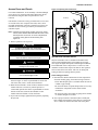
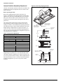
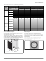
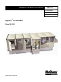
Installation and Maintenance Manual
IM 777-1
Group: Applied Air
Part Number: IM 777
Date: June 2005
Skyline¥ Air Handler
Sizes 003–090
© 2005 McQuay International
McQuay IM 782-1
1
Contents
General Information . . . . . . . . . . . . . . . . . . . . . . . . . . . . . . . 1
Operation Guidelines . . . . . . . . . . . . . . . . . . . . . . . . . . . . . 14
Receiving and Handling . . . . . . . . . . . . . . . . . . . . . . . . . . . . . 1
Unit Storage . . . . . . . . . . . . . . . . . . . . . . . . . . . . . . . . . . . . . . 1
Nomenclature . . . . . . . . . . . . . . . . . . . . . . . . . . . . . . . . . . . . . 1
Startup Checks . . . . . . . . . . . . . . . . . . . . . . . . . . . . . . . . . . . 14
Fan Wheel Alignment . . . . . . . . . . . . . . . . . . . . . . . . . . . . . . . 15
Operating Limits . . . . . . . . . . . . . . . . . . . . . . . . . . . . . . . . . . . 17
Fan Vibration Levels . . . . . . . . . . . . . . . . . . . . . . . . . . . . . . . 19
Vibration Causes . . . . . . . . . . . . . . . . . . . . . . . . . . . . . . 19
Installation Guidelines . . . . . . . . . . . . . . . . . . . . . . . . . . . . 2
Service Clearances . . . . . . . . . . . . . . . . . . . . . . . . . . . . . . . . . 2
Rigging . . . . . . . . . . . . . . . . . . . . . . . . . . . . . . . . . . . . . . . . . . 2
Curb Mounting and Unit Leveling . . . . . . . . . . . . . . . . . . . . . . 3
Assembling Sections . . . . . . . . . . . . . . . . . . . . . . . . . . . . . . . . 3
Access Doors and Panels . . . . . . . . . . . . . . . . . . . . . . . . . . . . 5
Injected-Foam Insulated Panels . . . . . . . . . . . . . . . . . . . 5
Field Mounting Junction Boxes and Other Components . . . . . 6
Duct Connections . . . . . . . . . . . . . . . . . . . . . . . . . . . . . . . . . . 6
Dampers and Hoods . . . . . . . . . . . . . . . . . . . . . . . . . . . . . . . . 7
Mounting Actuators . . . . . . . . . . . . . . . . . . . . . . . . . . . . . . . . . 7
Face and Bypass Section Mounting . . . . . . . . . . . . . . . . . . . . 7
Piping Vestibules . . . . . . . . . . . . . . . . . . . . . . . . . . . . . . . . . . . 8
Piping and Coils . . . . . . . . . . . . . . . . . . . . . . . . . . . . . . . . . . . 8
Water Cooling Coils . . . . . . . . . . . . . . . . . . . . . . . . . . . . . 8
Direct Expansion Coils . . . . . . . . . . . . . . . . . . . . . . . . . . 8
Steam Coils (see Figure 18 on page 10) . . . . . . . . . . . . . 9
Water Heating Coils . . . . . . . . . . . . . . . . . . . . . . . . . . . 11
Drain Pan Traps . . . . . . . . . . . . . . . . . . . . . . . . . . . . . . . . . . 11
Internal Isolation Assembly Adjustment . . . . . . . . . . . . . . . . 12
Electrical Installation . . . . . . . . . . . . . . . . . . . . . . . . . . . . . . . 13
Service and Maintenance . . . . . . . . . . . . . . . . . . . . . . . . . 20
Periodic Service and Maintenance . . . . . . . . . . . . . . . . . . . . 20
Ball Bearing Lubrication . . . . . . . . . . . . . . . . . . . . . . . . . . . . . 20
Fan Drive Adjustments . . . . . . . . . . . . . . . . . . . . . . . . . . . . . . 20
VM and VP Variable Pitch Key Type Sheaves . . . . . . . 21
LVP Variable Speed Sheaves . . . . . . . . . . . . . . . . . . . . 21
MVP Variable Speed Sheaves . . . . . . . . . . . . . . . . . . . . 22
Fan Drive Belt Adjustment . . . . . . . . . . . . . . . . . . . . . . . . . . . 24
General Rules of Tensioning . . . . . . . . . . . . . . . . . . . . . 24
Tension Measurement Procedure . . . . . . . . . . . . . . . . . 24
Front Load Filter Option . . . . . . . . . . . . . . . . . . . . . . . . . . . . . 25
Filter Gauges . . . . . . . . . . . . . . . . . . . . . . . . . . . . . . . . . . . . . 25
Maintaining the Coil . . . . . . . . . . . . . . . . . . . . . . . . . . . . . . . . 26
Winterizing Water Coils . . . . . . . . . . . . . . . . . . . . . . . . . . . . . 26
Removing and Replacing Components . . . . . . . . . . . . . . . . . 26
Removing the Fan Section . . . . . . . . . . . . . . . . . . . . . . . 26
Removing and Replacing the Coil . . . . . . . . . . . . . . . . . 27
Warranty . . . . . . . . . . . . . . . . . . . . . . . . . . . . . . . . . . . . . . . . . . 29
Warranty Return Material Procedure . . . . . . . . . . . . . . . . . . . 29
Replacement Parts . . . . . . . . . . . . . . . . . . . . . . . . . . . . . . . . 29
McQuay and MicroTech II are registered trademarks of McQuay International.
Microsoft is a registered trademark of Microsoft Corporation.
Windows is a trademark of Microsoft Corporation.
Copyright © 2005 McQuay International. All rights reserved throughout the world.
General Information
The system design and installation must follow accepted industry
practice as described in the ASHRAE Handbook, the National
Electric Code, and other applicable standards. Install this
equipment in accordance with regulations of authorities having
jurisdiction and all applicable codes.
Installation and maintenance must be performed by qualified
personnel familiar with applicable codes and regulations and
experienced with this type of equipment. Sheet metal parts,
self-tapping screws, clips, and such items inherently have sharp
edges; the installer should exercise caution.
CAUTION
SHARP EDGES AND COIL SURFACES
are a potential injury hazard. Avoid contact with them.
ATTENTION
Receiving and Handling
1 Carefully check items against the bills of lading to verify
all crates and cartons have been received. Carefully inspect
all units for shipping damage. Report damage immediately
to the carrier and file a claim.
2 Skyline air handler units are constructed of galvanized or
painted steel and are inspected thoroughly before leaving
the factory. Take care during installation to prevent
damage to units.
3 Take special care when handling the blower section. All
fans are dynamically balanced before leaving the factory.
Rough handling can cause misalignment or a damaged
bearings or shaft. Carefully inspect fans and shaft before
unit installation to verify this has not happened.
4 Screws, bolts, etc., for assembling sections are supplied in
Les bords tranchants et les surfaces des bobines sont un
risque de blessure. Ne les touchez pas.
a bag attached to each section. All necessary gasketing is
applied in the factory for section-to-section mounting.
Units require caulk sealant between sections.
Unit Storage
Store unit on a level surface. If air handling units are stored for
any period of time, periodically rotate the fan wheel to prevent
permanent distortion of drive components. In addition, grease
may settle in the lower part of the bearing, which can lead to
oxidation on the upper portion of the bearing surface. Keep the
fan bearings lubricated.
Nomenclature
OAH 003 G
Model
OAH = Outdoor air handler
OAC = Outdoor component
Nominal Unit Size
(nominal square foot of coil)
003, 004, 006, 008, 010, 012, 014, 017, 021, 025,
030, 035, 045, 055, 065, 080, 085, 090
Vintage of McQuay Air Handling Unit
D A C
Unit Cross Section
C = Standard unit cross section
M = Custom size cross section
Motor Location
A = Motor along side of fan housing
D = Motor downstream of belt drive plenum fan
F = Motor on inline fan
G = Motor downstream of direct drive plenum fan
T = Motor behind twin housed fans
Unit Type/Coil Position
B = Blow-thru cooling coil location
D = Draw-thru cooling coil location
H = Heating only
V = Vent only
McQuay IM 777-1
1
Installation Guidelines
Service Clearances
Figure 2: Service clearance for electrical power devices
In addition to providing adequate space around the unit for
piping coils and drains, access to at least one side of the unit is
always required to allow for regular service and routine
maintenance, which includes filter replacement, drain pan
inspection and cleaning, fan bearing lubrication, and belt
adjustment. Provide sufficient space—at least equal to the
length of the coil—on the side of the unit for coil removal. See
Figure 1 for servicing space requirements.
Maintain at least 54" of clearance in front of electrical power
devices. Electrical power devices that are mounted on the side
of the unit typically are up to 12" deep. See Figure 2.
1 2 "
Figure 1: Servicing space requirements
4 .0 0 " b a s e r a il e x te n s io n
5 4 "
W id th
Rigging
3 0 .0 0 "
W id th o f c o il s e c tio n
4 .0 0 "
Skyline air handlers ship as separate sections, completely
assembled, or in modules of assembled sections. The unit must
be rigged as it ships from the factory. Do not rig units after
assembly. Units are provided with a factory-installed base rail
and can be lifted using the 2" diameter lifting holes located in
the corners of each shipping section. To prevent damage to the
unit cabinetry, use spreader bars. Position spreader bars to
prevent cables from rubbing the frame or panels. Before hoisting
into position, test lift for stability and balance. Avoid twisting or
uneven lifting of the unit.
W id th o f
fa n s e c tio n
3 0
.0 0
"
2
H e ig h t
Figure 3: Unit and section rigging
McQuay IM 777-1
Installation Guidelines
Curb Mounting and Unit Leveling
Do not place a Skyline unit over an open curb unless it is
equipped with a curb-ready base. Installation instructions for
mounting units on a roof curb are provided in IM 770. For a
copy, contact your local McQuay representative or visit
www.mcquay.com. Make provisions under the unit to divert
any moisture from entering the building below.
For units without roof curb mounting, place the equipment
on a flat and level surface. Where surface irregularities
exist, shim the base of the unit at one or more points along
the length of the rails to prevent distortion or sagging.
Uneven or distorted sections cause misfit or binding of the
doors and panels and improper draining of drain pans. See
Figure 4.
Figure 5: Apply sealant to mating faces
1 /4 " d ia m e te r
b e a d c e n te re d
in fa c e o f
c le a r a n c e
U s e S p lic e
J o in t a s a
g u id e
Figure 4: Leveling the unit
2 Pull sections together to fasten. Use straps and a ratchet to
help pull the sections together securely. Apply sealant to
any gaps that may admit moisture.
3 Fasten base rails together first using the 3/8"-16 × 5" bolts
located in the splice kit provided with the unit. See
Figure 7.
a To fasten two shipping sections together, 4 bolts are
S h im s e c tio n s u n til
th e y a r e s tr a ig h t
a n d le v e l
S h im to p r e v e n t
d is to r tio n if w id th
is o v e r 1 0 8 "
Assembling Sections
If the unit is shipped in more than one shipping section, rig
each section into position separately. Shipping sections are
provided with a connection splice joint attached on the leaving
air side of the shipping section that seals against the frame
channel on the entering-air side of the adjoining section. The
splice joint is insulated and provides an air-tight seal between
two sections once they are assembled together. Align the splice
joint to seat into the mating gasket to provide an air seal. If the
splice joint was bent during shipping or rigging, restore it to its
original position. See Figure 7.
To assemble shipping sections:
needed (2 on each side of the unit). The bolts are run
from one base rail into the other and fastened with a nut.
Complete each section bottom and top before attaching
additional sections.
b If desired, shipping sections for non curb-ready units
can be fastened together internally. To fasten internally,
run field-provided #10 sheet metal screws or drill
screws (4" long, maximum) through the interior frame
channel of one unit into the splice joint of the
neighboring section.
c Handle units with curb-ready bases and vestibules so the
lifting bracket can be removed after the unit is placed on
the curbing.
– Remove the lifting bracket that projects inward over
the curbing. Save the self tapping screws.
– When the adjacent section is placed in position, use
self tapping screw to secure the bases together.
1 Caulk all assembly joints of the unit—Before joining the
sections, apply at least 1/4 inch diameter bead of sealant to
the mating faces of the cabinet. Use the splice joint as a
guide for applying the sealant. See Figure 5.
McQuay IM 777-1
3
Installation Guidelines
Figure 6: Remove vestibule lifting bracket
Figure 8: Internal fastening
A
S p lic e C o lla r
m u s t b e a lig n e d
to s e a l to g a s k e t.
R e m o v a b le
L iftin g B r a c k e t
4 Check that the sealant is compressed between the mating
Figure 7: Fasten bottom of section
channels when the unit sections are joined. Touch up any
places where gaps are noted.
5 After sections are seated tightly together, slip the splice cap
over the top panel flanges. Bend the ends of the splice cap
down to secure in place.
6 Assemble the small splice plate at the top rail to secure the
sections together at the top. Use 5/16" bolts. See Figure 9.
Figure 9: Splice cap and splice plate
S lid e S p lic e C a p o n
a n d b e n d e n d s d o w n
5 /1 6 - 1 8 B o lt
3 /8 x 1 " B o lt a n d N u t
4
5 /1 6 -1 8 N u t
S p lic e
P la te
McQuay IM 777-1
Installation Guidelines
Access Doors and Panels
Figure 10: Opening fan section door
For routine maintenance, access normally is obtained through
access doors or by removing side panels. Removing all flat
head fasteners along the sides of a panel allow it to be
removed.
Do Not Rotate Cup
Fan and filter sections are always provided with a service door
on one side of the unit. If requested on order, doors can be
provided on both sides of the unit. Optional service doors are
available for most section types and are provided based on
customer request.
Note – Opening fan section doors requires using a 1/2" socket
wrench, which satisfies ANSI standards and other codes
that require the “use of tools” to access compartments
containing moving parts or electrical wiring. See
Figure 10.
1 Remove padlock if one is present.
Jam
Nuts
CAUTION
SHARP EDGES AND COIL SURFACES
are a potential injury hazard. Avoid contact with them.
ATTENTION
Les bords tranchants et les surfaces des bobines sont un
risque de blessure. Ne les touchez pas.
CAUTION
DO NOT attempt to rotate the cup.
Damage to the unit will occur.
ATTENTION
NE PAS tenter de faire tourner la cuvette (cup).
Ceci va dendomagger l’unité.
2 Insert 1/2" socket into cup and rotate 1/4 turn clockwise as
shown in Figure 10. If the cup and handle are on the left
side of the door, rotate 1/4 turn counterclockwise.
3 Rotate the door handle 1/4 turn clockwise and then 1/4 turn
counterclockwise to release any internal pressure or
vacuum and open the door. If the cup and handle are on the
left side of the door, rotate the door handle 1/4 turn
counterclockwise and then 1/4 turn clockwise.
4 To prevent air leakage, tighten the door panels by adjusting
the jam nuts.
McQuay IM 777-1
View from inside door
OPEN
Injected-Foam Insulated Panels
Skyline air handlers now are furnished with double-wall,
injected-foam insulated panels. Foam panels are stronger,
more rigid, and lighter than panels with fiberglass insulation.
The insulation R-value is improved to 13. However, foam
insulation can burn when exposed to flame or other ignition
sources and release toxic fumes. Take care in cutting and
sealing all field-cut openings in these panels.
Panel cutting procedure
1 Determine the number and location of holes required for
electrical conduit, piping, and control wiring as follows:
• Check that adequate space is available inside the unit for
conduit or pipe routing.
• Do not locate holes in a panel that provides access to key
maintenance components such as filters and fan
assemblies.
• Do not locate where the conduit or piping blocks airflow
or obstructs hinged access doors.
2 Once a proper location is determined, drill a small pilot
hole completely through the panel. Then use a sharp hole
saw or a saber saw and cut from each side of the panel.
5
Installation Guidelines
3 Seal the double-wall panel on each side with an industrial/
commercial grade silicone sealant or duct seal compound.
It is extremely important to seal each panel hole or
penetration securely so it is airtight and watertight and
there is NO EXPOSED FOAM INSULATION.
WARNING
Flame and smoke can cause equipment
damage, severe personal injury, or
death.
Before operating unit, seal all piping and
wiring holes on both inner and outer panels
with an industrial grade silicone sealant or
duct seal compound. Do not use a cutting
torch or expose panel to fire. Panel
damage can occur.
inner panels. To maintain panel integrity, seal both ends with
an industrial/commercial grade silicone sealant or duct seal
compound.
The unit frame channel is another excellent location for
securing heavier components; self-tapping screws are not
acceptable. Ensure that the location permits the full operation
of all access doors and panels and does not interfere with other
vital components.
Duct Connections
Use flexible connectors on the outlet and inlet duct connections
of all units. Do not position down flow fans over air ducts that
are routed down into the building. Use a discharge plenum
when bottom connections are necessary. See Figure 12.
Figure 12: Discharge plenum
WARNING
La fumée et les flammes peuvent
endommager le matériel et causesr des
blessures graves ou la mort.
Avant d’utiliser le dispositif, obturer tous les
trous de passage de tubulures et de fils
ménagés dans les panneaux intérieurs et
extérieurs au moyen d’une pâte à base de
silicone ou d’un mastic d’étanchéite â
conduits de qualité industrielle.
Ne pas se servir d’un chalumeau coupeur ni
exposer les pannequx à une flamme nue
pour ne pas risquer de les endommager.
Figure 11: Cutting and sealing injected-foam insulated panels
Cut hole from both sides of panel
Seal completely with silicone
sealant or duct seal compound
D is c h a r g e
P le n u m
If the unit has a top mixing box or economizer damper or a top
duct connection, field fabricate and install flashing to divert
moisture from the connection. The flashing must lap over the
standing seams of the top panels. The flashing also must lap
over the side edges of the unit. See Figure 13.
Figure 13: Flashing over top panels and sides of units
F la s h in g
F la s h in g
D u c t
U n it to p
p a n e l
Prop 65—Substances in fuel or from fuel combustion can cause personal injury or death,
and are known to the State of California to cause cancer, birth defects or other reproductive harm.
F la s h in g
Field Mounting Junction Boxes and Other
Components
D u c t
F la s h in g
For field mounting 4" × 4" or smaller junction boxes to the
standard panel exterior, use a minimum quantity of 4, 3/16"
diameter pop rivets. Do NOT use self-tapping drill screws.
They will not tighten nor secure properly and panel
damage can occur.
If larger, heavier components require mounting on unit panels,
use through-bolts with flat washers through both outer and
6
McQuay IM 777-1
Installation Guidelines
Dampers and Hoods
Mounting Actuators
Side dampers may be provided in the mixing box and
economizer sections of units. When dampers are provided, a
removable panel is located above the weather hood to provide
access to the damper drive shaft. Other access may be available
depending on the specific construction of the unit. See Figure 14.
The installing contractor is responsible for the mounting of all
field-installed actuators. No provisions are made for the
location of these actuators due to the number of options and
arrangements available and the variety of specific applications.
Typically, actuators are mounted inside the cabinet. Provide
proper support for the actuator to avoid excessive stress in the
cabinet, linkage, or damper shafts.
Figure 14: Filler panel over the weather hood
Note – Damper blades are at full flow when open to 70 degrees.
Do not open blades further than 70 degrees.
Remove screws
and panel to access
damper control shaft.
Fresh air and return air dampers can be linked together and
driven from the same actuator if the dampers are the same size.
If the dampers are different sizes, they must be driven by
separate actuators and controlled appropriately. Exhaust
dampers are always driven by a separate actuator.
A typical rotary electric actuator can handle up to 40 sq. ft. of
damper. For pneumatic actuators, allow 5 in-lb per square foot
of damper area.
Hood
When units are ordered with exhaust hoods and intake hoods
adjacent to each other, install a field-supplied barrier to
prevent recirculation of exhaust air into the intake openings.
See Figure 15.
Figure 15: Field-installed barrier between hoods
CAUTION
Maximum damper rotation is 70°.
Maximum shaft torque is 205 inches/pound.
Greater rotation or torque can cause equipment damage.
ATTENTION
La rotation maximale des colets est de 70°.
Le couple (torque) maximum de l’arbre est de 205po/lb.
Une plus grande rotation (ou torque) peut endommager
l’équipement.
In ta k e
B a r r ie r
E x h a u s t
Face and Bypass Section Mounting
Internal and external face and bypass sections are mounted
together using the instructions for horizontal components and
do not require additional instruction. Skyline air handlers are
provided with a bypass duct that is integral to the unit
construction and requires no field assembly.
Face and bypass dampers may or may not be linked together.
When dampers are placed before a single bank of coils, they
always are linked together and require a single actuator. When
dampers bypass a stacked or staggered coil, the dampers are
not linked and require multiple actuators.
Face and bypass dampers have a torque requirement of
10 in-lbs per square foot of damper face area.
McQuay IM 777-1
7
Installation Guidelines
Piping Vestibules
Piping and Coils
For units that include a piping vestibule, cut the openings for
routing the field piping as required in the field. Carefully seal
passages cut through the panels to prevent air leakage. A
single metal thickness pan is provided in the bottom of the
curb-mounted vestibule. The pan can be removed if necessary.
If holes are cut into the pan for a piping passage, seal the holes
to prevent moisture leakage. See Figure 16.
When designing and installing piping:
Figure 16: Seal holes for piping—curb mounted units
• Support pipework independently of the coils.
• Follow applicable piping design, sizing, and installation
information in ASHRAE handbooks.
• Observe all local codes and industry standards.
• Do not apply undue stress at the connection to coil headers;
always use a backup pipe wrench.
Water Cooling Coils
Note – Use glycol in water coils for outdoor air handlers. Power
failures and other mechanical issues can expose coils to
freezing temperatures.
• Water supply, water return, drain, and vent connections
extend through the end panel of the coil section. All
connections are labeled on the end panel.
• Water supply and water return connections are typically
male NPT iron pipe.
• When installing couplings, do not apply undue stress to the
connection extending through unit panel. Use a backup
pipe wrench to avoid breaking the weld between coil
connection and header.
Seal holes
cut for piping
• Follow recommendations of the control manufacturer
regarding types, sizing, and installation of controls.
For units with standard base rails, the vestibule is open to the
coil section; therefore, seal all holes to prevent air leakage.
Figure 17: Seal holes for piping—standard base rail units
Direct Expansion Coils
• The coil distributor and suction connection extend through
the end panel of the coil section.
• Check nozzle in distributor for proper tonnage.
• When a thermostatic expansion valve is supplied with the
unit, it is located outside the unit and connected directly to
the distributor (except on units with piping vestibules). Do
not apply heat to the body of the expansion valve.
• The thermostatic expansion valve must be the external
equalizer tube type. Connect the 1/4-inch diameter external
equalizer tube provided on the coil to the connection on the
expansion valve.
Seal holes
cut for piping
8
• Use care when piping the system, making sure all joints are
tight and all lines are dry and free of foreign material. For
typical refrigerant piping, see condensing unit product manual.
McQuay IM 777-1
Installation Guidelines
Steam Coils (see Figure 18 on page 10)
Valves
Piping
• Do not use modulating steam valves on high pressure
systems.
• Steam supply and steam return connections typically are male
NPT iron pipe and are labeled on the end panel of coil section.
Connections extend through the coil section end panel.
• When installing couplings, do not apply undue stress to the
connection extending through unit panel. Use a backup
pipe wrench to avoid breaking the weld between coil
connection and header.
• Support piping independently of coils and provide adequate
piping flexibility. Stresses resulting from expansion of
closely coupled piping can cause serious damage.
• Do not reduce pipe size at the coil return connection. Carry
return connection size through the dirt pocket, making the
reduction at the branch leading to the trap.
Coils
• Pitch all steam coils in units toward the return connection.
• Do not drip supply mains through the coil.
• Do not attempt to lift condensate when using modulating or
on/off control.
• Install vacuum breakers on all applications to prevent
retaining condensate in the coil. Generally, connect the
vacuum breaker between the coil inlet and the return main.
The vacuum breaker should be open to the atmosphere and
the trap design should allow venting of large quantities of air.
• Properly size modulating valves. Do not undersize.
• Freezing conditions (entering air temperatures below 35°F).
– McQuay strongly recommends 5JA, 8JA, 5RA and 8RA
coils.
– Supply 5 psi steam to coils at all times.
• Do not use modulating valves. Provide control by face and
bypass dampers.
– Consider using two or three coils in series with two
position steam control valves on the coil or coils that
handle 35°F or colder air. Use a modulating valve on the
downstream coil to provide the desired degree of control.
– Thoroughly mix fresh air and return air before it enters the
coil. Also, to obtain true air mixture temperatures,
properly locate temperature control elements.
– As additional protection against freeze-up, install the trap
sufficiently below the coil to provide an adequate
hydrostatic head to remove condensate during an
interruption in the steam pressure. Estimate three feet for
each 1 psi of trap differential required.
– On startup, admit steam to coil ten minutes before
admitting outdoor air.
– Close fresh air dampers if steam supply pressure falls
below the minimum specified.
Traps
Note – Do not place steam traps outdoors.
• Size traps in accordance with the manufacturers’
recommendations. Make sure the required pressure
differential is always available. Do not undersize.
• Use float and thermostatic or bucket traps for low pressure
steam. On high pressure steam, use bucket traps. Use
thermostatic traps only for air venting.
• Use bucket traps for on/off control only.
• Locate traps at least 12 inches below the coil return connection.
• Multiple coil installation
– Individually trap each coil or group of coils that is
controlled individually trapped.
– Coils in series—use separate traps for each coil, or a bank
of coils.
– Coils in parallel—a single trap can be used, but an
individual trap for each coil is preferred.
– Do not attempt to lift condensate when using modulating
or on/off control.
• With coils arranged for series airflow, use a separate control
on each bank or coil in the direction of airflow.
McQuay IM 777-1
9
Installation Guidelines
Figure 18: Piping arrangements
Float and
thermostatic trap
Check Valve
Strainer
Control valve
modulating
two position
Gate Valve
High pressure (over 25 psi)
Vacuum breaker
1/2" check valve
Steam main
Vacuum breaker
1/2" check valve
1/4" petcock
for continuous
air venting
Steam main
Return main
1"
min.
1/4" petcock
for continuous
air venting
High pressure
float or bucket
trap
12" min.
1" min.
12" min.
High pressure
bucket trap
Full size of
return conn.
Return main
5GA or 8GA coils.
Note that the addition of a vacuum breaker to
permit the coil to drain during shutdown.
5TA, 8TA, or 5HA coils. Condensate
is lifted to overhead return main
Low pressure (to 25 psi)
Steam main
Vacuum breaker
1/2" check valve
Steam main
Steam main
Vacuum breaker
1/2" check valve
12" min.
Vacuum breaker
1/2" check valve
5J, 5G, 8J or 8G coils.
Return main
12" min.
Steam main
Return main
Vacuum breaker
1/2" check valve
5JA or 8JA coil. Installed in series.
Note that each coil must have a
separate control valve and trap.
Return main
5RA, 8RA, or 5SA coils. Banked two high, individu
trapping of each coil as shown is preferred.
12" min.
Return main
Full size of
return conn.
5RA, 8RA, or 5SA coils. Installed
10
McQuay IM 777-1
Installation Guidelines
Figure 19: Allow adequate distance between trap outlet
and drain pan outlet
Water Heating Coils
CAUTION
Improper installation, use, or maintenance of water
heating coils can cause equipment damage.
Read and follow instructions carefully.
P re s s u re (P )
a t th e d r a in p a n
2 P
ATTENTION
Si l’installation, l’utilisation ou l’entretien des
serpentins de chauffage à eau sont inadéquats,
ceci endommagera l’équipement.
Lire et suivre attentivement les instructions.
• Water supply and water return connections extend through
the end panel of the coil section. All connections are labeled
on the end panel.
• Water supply and water return connections are male NPT
iron pipe.
• When installing couplings, do not apply undue stress to the
connection extending through unit panel. Use a backup pipe
wrench to avoid breaking the weld between the coil
connection and header.
2 P
Note – The door panels on some applications have a close
clearance over the drain pipes. Extend the drain fitting
with a coupling if necessary for door clearance. See
Figure 20.
– Use material that can withstand freezing temperatures for
outdoor drain traps.
– Drain traps that dry out can allow cold air to seep into the
equipment.
Figure 20: Extend drain fitting for door clearance
• Follow recommendations of the control manufacturer
regarding types, sizes, and installation of controls.
• Do not use hot water coils with entering air below 40°F.
• If fresh air and return air are to be heated by a hot water coil,
carefully design the system to provide thorough mixing
before air enters the coil.
C le a r a n c e
• To prepare coils for winter operation, see “Removing and
Replacing Components” on page 26.
Drain Pan Traps
Run drain lines and traps full size from the drain pan
connection. Install drain pan trap to allow condensate to drain
freely. On both blow-through and draw-through units, the trap
depth and the distance between the trap outlet and the drain
pan outlet must be twice the static pressure in the drain pan
section under normal operation so the trap remains sealed. See
Figure 19.
McQuay IM 777-1
D r a in
11
Installation Guidelines
Internal Isolation Assembly Adjustment
Figure 21: Removing shipping brackets
On units with internally isolated fan and motor assemblies, the
assemblies are secured for shipment with a tie-down at each
point of isolation.
Before operating the unit:
Remove the shipping brackets and tie-down bolts (see
Figure 21) and discard. The shipping brackets located on the
opposite drive side of the unit are difficult to access from the
drive side of the unit. Either remove them before the unit is
assembled, or remove the panel on the opposite drive side to
gain access.
The spring isolators under the four corners of the fan and
motor assembly are factory adjusted while the fan was not
running. See Table 1 below. With the unit operating at normal
cfm and static pressure, all the isolators should be at the same
height opening. If adjustments are required, loosen the 1/2"
cap screw on top of the isolator and turn the adjusting bolt to
lower or raise the fan and motor base. Retighten the cap screw
when adjustments are completed.
S h ip p in g b r a c k e t
r e m o v e a n d d is c a r d
( T y p ic a l 4 p la c e s )
S e e d e ta il " A "
S p r in g h e ig h t
a d ju s tm e n t
s c re w
D im
Table 1: Spring mount adjustments
S h ip p in g h o ld d o w n
r e m o v e a n d d is c a r d
( T y p ic a l 4 p la c e s )
"H "
Spring mount adjustment at rest
Fan discharge position
Top or bottom horz. H
Unit sizes 003–035
1
3.75
2
4.25
3
4.25
4
3.75
P O S 2
P O S 3
M o to r
Unit sizes 04–-090
A ir flo w
F a n
1
6.00
2
6.50
3
6.50
4
6.00
For models 040 through 090, the isolators should be at equal
height during fan operation (6"). Center the fan outlet in the
outlet panel opening. If adjustment is required, loosen the cap
screw on top of the isolator assembly. Turn the adjustment nut
below the fan frame to lower or raise the fan motor and frame
assembly. Retighten the cap screw on top of the isolator
assembly.
P O S 1
P O S 4
F a n is o la to r p o s itio n n u m b e r s
S h ip p in g h o ld
d o w n s c re w
S p r in g h e ig h t
a d ju s tm e n t s c r e w
S h ip p in g
b ra c k e t
D e ta il A
12
McQuay IM 777-1
Installation Guidelines
Electrical Installation
• Electrical service to the fan must correspond to the rated
voltage on the motor nameplate and conform to the National
Electric Code and local restrictions.
• Connect the fan section metal frame to the building
electrical ground.
• A door electrical interlock is not provided as standard.
• Thermal motor protection is external to the unit.
Locate electrical conduit entrances for units above the bottom
of the unit, high enough to clear components inside, but below
the bottom of the fan motor junction box. See Figure 22.
Figure 22: Electrical conduit location
Fan motor
junction box
Conduit entrance
(typical)
CAUTION
The base section of each cabinet has a drip pan installed
below every panel that drains to the outside frame trough. Any
holes cut through the bottom of the unit must also penetrate
the drip pan. If holes are cut in the drip pan, seal them to
prevent moisture leakage.
ATTENTION
Chaque cabinet est muni d’une base avec une panne
d’égouttement installée en-dessous de chaque panneau qui
évacuera l’eau vers la gouttière extérieure. Tous les trous
percés au bas de l’unité doivent pénétrer la panne
d’égouttement. S’il y a des trous dans la panne
d’égouttement, les sceller pour empêcher les fuites d’eau.
McQuay IM 777-1
13
Operation Guidelines
Startup Checks
When performing startup and service, always take thorough
safety precautions. Only trained, experienced personnel
should perform these functions.
WARNING
ROTATING FAN
Can cause severe injury or death. Before servicing fans,
lockout and tag out power.
AVERTISSEMENT
VENTILATEUR EN ROTATION
Peut causer des blessures sévères ou même la mort.
Avant d’effectuer l’entretien des ventilateurs,
bloquer et couper la tension.
WARNING
FIRE/ELECTRIC SHOCK HAZARD.
Can cause property damage, personal injury or death.
Wire fan power supply and ground motor frame in accordance
with local electric codes.
AVERTISSEMENT
Risques d´incendie et d’électrocution pouvant causer des
dommages matériels, des blessures et même la mort.
L’alimentation électrique du moteur du ventilateur de même
que la mise à la terre du chàssis du moteur doivent être faits
conformément aux codes d’nstallations électriques en
vigueur.
WARNING
Fan motor requires overload protection.
Failure to provide motor overload protection can result in fire,
property damage, electric shock, personal injury, or death.
Connect motor to an overload protective device rated in
compliance with local electric codes.
AVERTISSEMENT
Risques d’incendie et d’électrocution pouvant causer des
dommages matériels, des blessures et même la mort.
Connecter au moteur du ventilateur électrique un dispositif de
protection contre les surcharges conforme aux codes
d’installations électriques en vigueur.
CAUTION
DO NOT OVERHEAT FAN MOTOR
High air temperatures in the fan section can cause the fan
motor to burnout. On draw-through air handlers or air handlers
with the fan section down the air stream from the heating
section, the discharge air temperature of the heating section
must not exceed 104°F (40°C).
ATTENTION
Risques de dommages dans le moteur du ventilateur
électrique. Si Ia température de l’air a proximité du
ventilateurest élevée, le moteurdu ventilateur électrique peut
chauffer et brûler. Sur les transmetteurs d’air à circulation
transversale ou les transmetteurs dont le ventilateur est en
aval de l’unité de chauffage, régler la température de l’air
sortant de l’unité de chauffage à 40°C (104°F).
Before starting the unit:
Before entering fan section, make sure that fan electrical
power source is disconnected and locked in the OFF position.
1 Check that the unit is completely and properly installed
with ductwork connected.
2 Check that all construction debris is removed and filters
are clean.
3 Check that all electrical work is complete and properly
terminated.
4 Check that all electrical connections are tight and that the
proper voltage is connected. Phase imbalance must not
exceed 2%.
5 Check that ball bearings on the fan shaft and motor are
prelubricated and do not need grease before startup.
6 Check tightness of setscrews in bearings and fan wheel(s).
If retightening is needed, position the fan wheel(s) per
Table 2 or Table 3 on page 15. Torque set screws per
Table 6 on page 16.
CAUTION
Equipment damage due to loose fasteners represents
improper start-up and equipment abuse. It is not covered by
the warranty.
ADVERTISSEMENT
Les dommages dus à des attaches installées de façon
inappropriée représentent un démarrage inadéquat et un
abus d’équipement. Ceci n’est pas couvert par la garantie.
14
McQuay IM 777-1
Operation Guidelines
7 Check alignment of fan and motor sheaves and belt tension.
Adjust if necessary. Check tightness of sheave setscrews
and/or capscrews. See Figure 35 and Figure 36 on page 24.
8 Leak test the thermal system to verify that connections are
3. To obtain dimension B, loosen screw and washer fasteners around
periphery of funnel(s), shifting funnel radially as required, and re-torquing
fasteners.
Figure 24: Wheel-to-inlet funnel relationship—forward
curved type fan wheels
tight.
C
9 Check that the condensate drain is trapped.
10 Rotate the shaft by hand to be sure it is free.
C
W h e e l
In le t
F u n n e l
Fan startup:
Start and run fan. Observe the rotation. If the fan operates
backward, reverse two legs of the three-phase supply power.
Note – Variable pitch fan drives usually are provided for operation
in the mid-speed adjustment range. However, the drives
usually ship with the adjustment opened up for minimum
fan speed. Adjust the drives for the proper airflow. See
“Fan Drive Adjustments” on page 20.
After the first 48 hours of operation:
1 Disconnect and lock electrical power source.
2 Check tightness of all bearing, wheel, and sheave setscrews
(or capscrews). See Table 6.
3 Recheck belt tension and adjust if necessary. Belts
tensioned sufficiently to slip one to two seconds at startup
will perform satisfactorily, extending life and reducing
vibration. If retensioning is necessary, be certain to retain
sheave alignment.
Fan Wheel Alignment
In le t
F u n n e l
Table 3: Wheel-to-inlet funnel relationship—forward curved
type fan wheels
Forward curved
Unit sizes 003 to 035
Diameter \(in)
Unit sizes 040 to 090
C
C (in)
(mm)
Diameter (in)
C (in)
C
(mm)
9x4
0.25
6.35
20 (Class 1 & 2)
0.24
6.10
9x7
0.13
3.30
22.38 (Class 1 & 2)
0.41
10.41
9x9
0.25
6.35
25 (Class 1 & 2)
0.47
11.94
10
0.22
5.59
27.62 (Class 1 & 2)
0.47
11.94
12
0.35
8.89
30 (Class 1 & 2)
0.47
11.94
15
0.44
11.18
33 (Class 1 & 2)
0.50
12.70
18
0.25
6.35
36 (Class 1 & 2)
0.75
19.05
20 (Class 1 & 2)
0.73
8.54
22 1/2 (Class 1 & 2) 0.59
14.99
24 1/2 (Class 1 & 2) 0.56
14.22
Notes:
1. To obtain rated air performance, dimensional relationship must be held.
2. Adjust dimension C by loosening wheel hub set screws, shifting wheel(s)
axially as needed, and retightening set screws.
Figure 23: Wheel-to-inlet funnel relationship—airfoil type f
an wheels (housed)
B
A
E q u a l s p a c in g
a ll a r o u n d
A
Table 2: Wheel-to-inlet funnel relationship—airfoil type
Airfoil
Unit sizes 003 to 035
Unit sizes 040 to 090
A
(mm)
B
(in)
B
(mm)
A
(mm)
A
(in)
B
(mm)
13.22 4.56
116
0.21
14.56 5.06
129
0.21
5.33 20.00 7.19
183
0.31
7.87
5.33 22.25 7.69
195
0.33
16.18 5.62
143
8.38
0.21
5.33 24.50 8.56
217
0.31
17.69 6.90
7.87
175
0.22
5.59 27.00 9.47
241
0.63 16.00
21.56 7.59
193
0.24
6.10 30.00 10.47
266
0.39
9.91
24.00 8.45
215
0.23
5.84 33.00 11.75
298
0.38
9.65
36.50 12.78
325
0.38
9.65
40.25 14.31
363
0.50 12.70
Dia.
A
(in)
Dia.
A
(in)
Notes:
1. To obtain rated air performance, dimensional relationship must be held.
2. To obtain dimension A, loosen setscrews in wheel hub(s), shifting wheel(s)
axially as needed, and retightening setscrews.
McQuay IM 777-1
15
Operation Guidelines
Figure 25: Wheel-to-inlet funnel relationship—plenum fans
Figure 26: Wheel-to-inlet funnel relationship—inline fans
Overlap
Overlap
Table 4: Wheel-to-inlet funnel relationship—plenum fans
Table 5: Wheel-to-inlet funnel relationship—inline fans
Wheel—funnel overlap
16
Wheel—funnel overlap
Size
Overlap
13.5
.120
Size
Overlap
15
.190
16.5
.250
150
165
182
200
222
245
270
300
330
365
402
445
.375
.438
.562
.625
.688
.750
.812
.875
1.000
1.125
1.250
1.375
18.25
.310
20
.380
22.25
.440
24.5
.500
27
.560
30
.620
33
.750
36.5
.810
40.25
.880
44.5
.940
49
1.000
54.25
1.060
60
1.120
Table 6: Bearing collar and wheel hub set screw torque
set screw
Diameter (in)
Minimum torque
ft/lbs
kg/m.
1/4
5.5
.76
1/16
10.5
1.45
3/8
19.0
2.63
7/16
29.0
4.01
1/2
42.0
5.81
5/8
92.0
12.72
McQuay IM 777-1
Operation Guidelines
Operating Limits
Do not exceed the operating limits in Table 7. A fan wheel
operated beyond the rpm and temperature limits shown can
suffer permanent distortion or fracture. The resulting
unbalance can cause severe unit vibration.
Table 7: Unit sizes 003 to 035
Fan operating limits
Forward curved—housed
Diameter
9×4
9×7
9×9
10.62
12.62
15
18
20
22.25
24.50
Maximum rpm Class I
N/A
2189
2223
1934
1614
1328
1155
1050
944
858
Maximum rpm Class Il
2244
2854
2896
2518
2091
1725
1450
1200
1030
910
Diameter
13.22
14.56
16.19
19.69
21.56
24.00
Maximum rpm Class I
3000
3000
2300
2000
1700
1500
Maximum rpm Class Il
4335
3918
3457
2858
2427
2255
Airfoil—housed
Figure 28: Torque for AF variable inlet vanes (in–lb)
2
.2
3
F1
A
4500
100
90
80
70
60
50
40
35
30
56
4.
1
AF
4000
150
1500
450
500
550
600
650
700
750
800
850
900
1000
400
300
350
200
Fan speed (rpm)
19
6.
1
AF
750
800
850
900
1000
F
150
100
90
80
0
.0
0
C2
69
9.
1
AF
3500
2
FC
56
1.
2
AF
3000
8
3
2.
00
4.
2
AF
1500
200
250
Torque (in–lb)
250
Torque (in–lb)
FC
FC 36.
0
FC 33. 0
00
3
0.
FC
25
27
.
62
FC
25
.0
0
400
350
300
450
400
350
300
250
200
2500
500
2000
Figure 27: Torque for FC variable inlet vanes (in–lb)
Fan speed (rpm)
Table 8: Unit sizes 040–090
Fan operating limits
Forward curved—housed
Diameter
20
22.38
25
27.62
30.25
33
36
Maximum rpm Class I
1010
930
790
690
650
600
560
Maximum rpm Class Il
1281
1178
1011
910
835
763
715
Airfoil—housed
Diameter
20
22.25
24.5
27
30
33
36.5
Maximum rpm Class I
2077
1875
1691
1479
1328
1209
1073
Maximum rpm Class Il
2703
2413
2199
1928
1730
1579
1401
McQuay IM 777-1
17
Operation Guidelines
Figure 29: Torque for FC variable inlet vanes (in–lb)
300
250
2000
.
24
150
1500
Torque (in–lb)
FC
200
Torque (in–lb)
50 .25
0
22
.0
20
FC
C
F
0
.0
0
18
.0
FC
15
FC
Figure 30: Torque for AF variable inlet vanes (in–lb)
2
.6
12
FC
100
90
80
70
60
25
0.
4
AF
1000
900
800
700
600
500
400
350
300
250
200
0
.5
38
AF
00
3.
3
AF
00
0.
3
AF
00
0
.5
24 .25
0
AF F22
.0
A
20
F
A
7.
2
AF
150
3000
49
54.25
60
2000
1500
550
600
650
700
750
800
850
900
1000
Fan speed (rpm)
2500
100
2000
1500
500
550
600
650
700
750
800
850
900
1000
450
400
350
50
Fan speed (rpm)
Table 9: Operating limits—plenum fans
Fan operating limits
Plenum fans
Diameter
13.5
15
16.5
18.25
20
22.25
24.5
27
30
33
36.5
40.25 44.50
Maximum rpm Class I
2895
2589
2376
2256
2077
1875
1691
1479
1328
1209
1073
972
882
799
725
651
Maximum rpm Class II
3786
3384
3100
2959
2703
2413
2199
1928
1730
1579
1401
1264
1150
1043
938
847
Maximum rpm Class III
4000
4000
3887
3735
3409
3065
2780
2423
2182
1984
1756
1598
1447
1314
1178
1071
Figure 31: Torque requirements at 100% WOV for SWSI
plenum fans with NESTED inlet vane
60
0
5000
54
2
4000
49
0
3000
44
5
1000
900
800
700
40
2
36
5
Torque
(in-lb
)
Torque
(lb./in.)
2000
600
33
0
500
300
400
270
300
245
200
3000
2000
1500
700
800
900
1000
600
500
400
300
200
100
Fan Speed (rpm)
18
McQuay IM 777-1
Operation Guidelines
Fan Vibration Levels
Each unit as shipped is trim balanced to operate smoothly. To
provide satisfactory operation after shipping and installation,
use the accepted industry guidelines for field balancing fans.
See Table 10.
b Loose set screws in wheel hub or bearing-to-shaft
c Wheel distorted from overspeed
2 Bent shaft
3 Drive faulty
Table 10: Vibration levels
a Variable pitch sheaves—Axial and radial runout of
Fan speed (rpm)
Vibration
800 or less
5 mils maximum displacement
801 or greater
0.20 in/sec. maximum velocity
flanges; uneven groove spacing; out of balance. Also
similar faults in driven sheave.
Note: Excessive vibration from any cause contributes to premature fan and
motor bearing failure. Monitor overall vibration levels every six months
of operation. An increase in levels is an indication of potential trouble.
Vibration Causes
1 Wheel imbalance
b Bad V-belts; lumpy, or mismatched; belt tension too
tight or too loose.
4 Bad bearings, loose bearing hold-down bolts
5 Motor imbalance
6 Fan section not supported evenly on foundation
a Dirt or debris on wheel blades
Table 11: Operating limits—inline fans, twin fans
Fan operating limits
Inline fans
Diameter
18.25
20
22.25
24.5
27
30
33
36.5
40.25
44.50
49
Maximum rpm Class I
2727
2488
2236
2041
1835
1665
1476
1330
1208
1072
973
54.25
880
Maximum rpm Class II
3409
3111
2796
2551
2294
2082
1846
1662
1510
1340
1216
1100
Diameter
9x9
10.62
12.62
15
18.12
20
Maximum rpm
2575
2400
2000
1700
1400
1200
Maximum HP
10
15
15
30
40
40
Twin fans
McQuay IM 777-1
19
Service and Maintenance
Periodic Service and Maintenance
1 Check all moving parts for wear every six months.
2 Check bearing collar, sheave, and wheel hub setscrews,
sheave capscrews, and bearing hold-down bolts for
tightness every six months.
1 Motor bearings—All ball bearings are prelubricated and do
not require additional grease at time of installation.
However, periodic cleaning out and renewal of grease is
necessary. Exercise extreme care to prevent foreign matter
from entering the bearing. It also is important to avoid over
greasing. Use a high grade, clean mineral grease with the
following characteristics:
• Melting point over 302°F (150°C)
• Free from oil and soap separation under operating and
storage conditions
• Free of abrasive matter, acid, alkali and moisture
Specific greasing instructions are located on a label
attached to the fan section door.
2 Fan shaft bearings—All ball bearings are prelubricated and
do not require addition of grease at time of installation.
However, periodic renewal of grease is necessary.
Bearings are accessible through access door in fan section.
Grease fittings are located in front of door opening on
drive end of blower section. Apply grease slowly until a
very slight bleeding of grease from the seals is noted. Tie
hinged door(s) open. Do not over lubricate. Wipe off any
excess grease to prevent overheating.
The lubrication interval varies with the period of operation
and temperature of the ambient air. Use the guidelines in
the table below:
Table 12: Lubrication guidelines
Bearing operating temp range
to 130°F
(54°C)
Manufacturer
Product name
Texaco Lubricants Company
Premium RB
Keystone Ind. Lubricants
Ball Bearing Lubrication
Temperature
Table 13: Lubricants recommended for fan shaft ball
bearings
to 150°F
(66°C)
over 150°F
(66°C)
Continuous operation:
6 months
4 months
2 months
12-hr. day operation:
12 months
12 months
6 months
Mobil Oil Corporation
Chevron U.S.A. Inc.
Exxon Company, U.S.A.
Shell Oil Company
81EP-2
Temp. range
°F
°C
–30 to 300 –34 to 149
0 to 250
–18 to 121
Mobilith SCH100 –40 to 350 –40 to 177
SRI-2
–20 to 325 –29 to 163
Ronex MP
–40 to 300 –40 to 149
Alvania No. 2
–20 to 240 –29 to 116
Note: Temperature ranges over 225°F are shown for lubricants only. High
temperature applications are not suitable for standard air handler
components.
Fan Drive Adjustments
WARNING
Before servicing fans, lock out and tag out all power to the unit.
Fans or belts can cause severe personal injury or death.
AVERTISSEMENT
Avant de faire le service sur les ventilateurs,couper et indiquer
que le courant est coupé. Les ventilateurs ou les courroies
peuvent causer des blessures personnelles graves ou
entraîner la mort.
WARNING
Do not open the hinged access door and screw-fastened
access panels while the unit is operating. Moving parts and
strong suction forces can cause severe personal injury or
death
AVERTISSEMENT
Ne pas ouvrir les portes d’accès à charnières et les panneaux
à vis lorsque l’unité fonctionne. Les pièces mobiles et le niveau
de succion peuvent causer des blessures personnelles graves
ou même entraîner la mort.
Upon completion of the air balance, replace the variable
pitched motor sheave with a properly sized, fixed sheave. A
matching fixed sheave provides longer belt and bearing life
and minimizes vibration. Initially, it is best to have a variable
pitched motor sheave for the purpose of air balancing. Once
the balance is achieved, fixed sheaves maintain balancing and
alignment more effectively. Replace the adjustable sheaves
with fixed sheaves.
With the electrical power disconnected, locked and tagged
out, measure the diameter of the V-belt outer surface where it
20
McQuay IM 777-1
Service and Maintenance
passes around the sheave (pitch diameter). Calculate fan speed
from the motor nameplate rpm.
Fan rpm = motor rpm ×
Figure 32: VP type sheave adjustment
A
Measured diameter at motor sheave
B
Measured diameter at fan sheave
VM and VP Variable Pitch Key Type Sheaves
Mounting:
E
Single Groove
1 Mount all sheaves on the motor or driving shaft with the
setscrews A toward the motor.
D
2 Verify that both driving and driven sheaves are in
alignment and that shafts are parallel.
3 Fit internal key D between sheave and shaft and lock
setscrew A securely in place.
Key E projects
to provide a grip
for removal.
1 Loosen setscrews B and C in moving parts of sheave and
pull out external key E. (This key projects a small amount
D
C
3 Replace external key E and securely tighten setscrews B
over key and setscrews C into keyway in fixed half of the
over grooves. See “Fan Drive Belt Adjustment” on page
24.
5 Make future adjustments by loosening the belt tension and
increasing or decreasing the pitch diameter of the sheave by
half or full turns as required. Readjust belt tension before
starting drive.
6 To provide the same pitch diameter, adjust both halves of
the two-groove sheaves by the same number of turns from
closed position.
7 Verify that all keys are in place and that all se screws are
tight before starting drive. Check setscrews and belt tension
after 24 hours service.
E
Two Groove
moving parts by half or full turns from closed position. Do
not open more than five full turns for A belts or six full
turns for B belts.
4 Put on belts and adjust belt tension. Do not force belts
B
A
to provide a grip for removing.)
sheave.
Do not operate
sheeves with flange
projecting beyond
the hub end.
B
Adjusting:
2 To adjust sheave pitch diameter for desired speed, open
C
C
LVP Variable Speed Sheaves
Mounting:
1 Slide sheave on motor shaft so that the side of the sheave
with setscrew A is next to the motor when setscrew A is in
the hub or barrel of the sheave.
2 When setscrew A is at an angle in the center flange B,
mount it away from the motor so that the outer locking ring
and flange can be removed to get to the setscrew.
3 To remove the flange and locking ring:
a Loosen setscrews D.
b Loosen but do not remove capscrews E.
c Remove key F.
Note: This key projects a small amount to provide a grip
for removing.
d Rotate the flange counterclockwise until it disengages
the threads on the sheave barrel.
4 Verify that the driving and driven sheaves are in alignment
and the shafts are parallel. When aligning two-groove
sheaves, allow room between the sheave and motor to
access capscrews E.
5 Insert key C between the sheave and the shaft and tighten
setscrew A securely.
6 If flange and locking ring have been removed, when
replacing them make sure that the inner and outer flanges
are open from the closed position by the same amount as
McQuay IM 777-1
21
Service and Maintenance
the other flange. Determine this by accurately measuring
the top width of the grooves.
9 Before starting the drive, ensure that all keys are in place
and all setscrews and all capscrews are tight. Check and
retighten all screws and retension belts after approximately
24 hours of operation.
7 Insert key F.
8 Tighten setscrews D and capscrews E.
MVP Variable Speed Sheaves
9 Put on belts and adjust belt tension. Do not force belts
over grooves. See “Fan Drive Belt Adjustment” on page
24.
Mounting:
1 Verify both driving and driven sheaves are in alignment and
10 Before starting the drive, ensure that all keys are in place
and all setscrews and all capscrews are tight. Check and
retighten all screws and retension belts after approximately
24 hours of service.
the shafts are parallel. The centerline of the driving sheave
must be in line with the centerline of the driven sheave. See
Figure 34.
2 Verify that all setscrews are torqued to the values shown in
Table 14 before starting drive. Check setscrew torque and
belt tension after 24 hours of service.
Adjusting:
1 Slack off belt tension if belts have been installed.
2 Loosen setscrews D.
Adjusting:
1 Adjust motor base forward to release belt tension. Remove
3 Loosen but do not remove capscrews E.
the belts for easier adjustment.
4 Remove key F.
2 Loosen, but do not remove both of the locking setscrews A
Note: This key projects a small amount to provide a grip
in the outer locking ring by using a hex key or torque
wrench with a hex bit.
for removing.
5 Adjust pitch diameter by opening or closing the movable
3 Adjust sheave to desired pitch diameter by turning the outer
flanges by half or full turns.
locking ring. Use a spanner wrench or drift inserted into the
three holes that are located 120° apart on the ring.
Note: Two-groove sheaves are supplied with both grooves
set at the same pitch diameter.
4 Any pitch diameter can be obtained within the sheave
To provide the same pitch diameter for satisfactory
operation, move both movable flanges the same number of
turns. Do not open sheaves more than five turns for A belts
or six turns for B belts.
range. One complete turn of the outer locking ring changes
the pitch diameter 0.233".
5 Do not open sheaves more than the following
• Do not open B sheaves more than 4 3/4 turns for the A
6 Replace key F.
belts or 6 turns for the B belts.
7 Tighten setscrews D and capscrews E
• Do not open C sheaves more than 9 1/2 turns.
8 If belts have been installed, readjust belt tension. If belts
• Do not open 5V sheaves more than 6 turns.
have not been installed, install them and adjust belt tension.
Do not force belts over grooves. See “Fan Drive Belt
Adjustment” on page 24.
• Do not open 8V sheaves more than 8 turns.
Figure 33: LVP type sheave adjustment
A
A
A
E
E
E
C
C
F
A
F
D
D
D
B
Section A-A
22
Section A-A
McQuay IM 777-1
Service and Maintenance
6 Tighten BOTH locking screws A in the outer locking ring
8 Do not loosen any screws other than the two locking screws
A in the outer locking ring when adjusting the sheave pitch.
before operating the drive. Use a torque wrench and tighten
to the value shown in Table 14.
Do not operate the drive until the locking screws have been
set to the torque specifications.
7 Replace belts and adjust the motor base to tension the belts
properly. See Figure 36.
Table 14: Screw torque values
Hollow head set screws only
Socket head cap screws
Flat head socket
screws
Seating torque
Seating torque
Seating torque
Seating torque
Length (L)
Seating torque
Nominal screw size
(dia–-thds/in)
Lengths equal or greater than dia.
For lengths (L)) less than dia.
(in–lbs)
(in–lbs)
(in–lbs)
(in–lbs)
(in–lbs)
(in–lbs)
(in–lbs)
1/4–20NC
150
12.5
100
87
7.3
3/16
50
5/16–11NC
305
25.4
200
165
13.8
1/4
90
3/8–16NC
545
45.4
350
290
24.2
1/4, 5/16
150, 250
1/2–13NC
1300
108.3
N/A
620
51.7
N/A
N/A
5/8–11NC
N/A
N/A
N/A
1225
102.1
N/A
N/A
Figure 34: Sheave adjustment
M u s t b e
p a r a lle l
B e a r in g
C e n te r lin e s
m u s t c o in c id e
M o to r
M u s t b e
p a r a lle l
A d ju s ta b le
S h e a v e
Figure 35: Sheave adjustment
A d ju s ta b le
C e n te r - F la n g e
F ix e d
C e n te r - F la n g e
( 2 ) L o c k in g
S e ts c re w s "A "
F la th e a d S o c k e t S c r e w s
(D o N o t R e m o v e )
S p lit T a p e r
B u s h in g
C a p s c re w s
(D o N o t R e m o v e )
McQuay IM 777-1
S ta tio n a r y
E n d - F la n g e
O u te r
L o c k in g - R in g
In n e r L o c k in g - R in g
( 3 ) H o le s fo r
S p a n n e r W re n c h
o r D r ift
23
Service and Maintenance
Fan Drive Belt Adjustment
General Rules of Tensioning
1 The ideal tension is the lowest tension at which the belt
does not slip under peak load conditions.
2 Check tension frequently during the first 24 to 48 hours of
operation.
3 Over tensioning shortens belt and bearing life.
4 Keep belts free from foreign material that can cause
slippage.
5 Inspect V-drive on a periodic basis. Adjust tension if the
belt is slipping. Do not apply belt dressing. This can
damage the belt and cause early failure.
Tension Measurement Procedure
1 Measure the belt span. See Figure 36.
2 Place belt tension checker squarely on one belt at the center
of the belt span. Apply force to the checker, perpendicular
to the belt span, until the belt deflection equals belt span
distance divided by 64. Determine the force applied while
in this position.
3 Compare this force to the values in Table 15.
Figure 36: Drive belt adjustment
Deflection =
Belt span
24
Belt span
64
WARNING
Moving belt and fan can cause severe personal injury or death.
During installation and filter maintenance:
• Verify that the belt and fan guards on plenum fan units are
always in place.
• Lock and tag out fans to prevent accidental start up.
• Do not enter the filter compartment until the fan is
completely stopped.
• Use approved equipment for reaching filters located above
normal reach. Do not step on filter frames or unit
components.
• Floor surfaces must be dry and free of oil or grease.
WARNING
Pendant l’installation et où l’entretien des filtres, une courroie
en mouvement ou un ventilateur en opération peuvent causer
des blessures graves où même causer la mort.
• S’assurer que les gardes de courroie et de ventilateur sont
toujours en place.
• Verouiller les démarreurs des ventilateurs et afficher un
avis de mise-en-garde afin de prévenir tout accident ou
démarrage.
• Attendre que le ventilateur soit complètement arrêté avant
d’entrer dans l’unité.
• Utiliser seulement des équipements approuvé pour joindre
les bancs de filtres; ne pas mettre soit sur les cadres des
filtres ou même sur toutes composantes de l’unité.
• La surface des planchers doit être sec et libre de toute
trace d'huile et où de graisse.
McQuay IM 777-1
Service and Maintenance
Table 15: Belt deflection force (per Browning specifications)
Sheave diameter (in)
Cross
section
Smallest
sheave
diameter range
3.0 to 3.6
A, AX
3.8 to 4.8
5.0 to 7.0
3.4 to 4.2
B, BX
4.4 to 5.6
5.8 to 8.6
4.4-6.7
5V, 5VX
7.1-10.9
11.8-16.0
Deflection force (lbs)
Cross section A, B, 5V
Cross section AX, BX, 5VX
rpm
range
Used belt
New belt
Used belt
New belt
1000 to 2500
3.7
5.5
4.1
6.1
2501 to 4000
2.8
4.2
3.4
5.0
100 to 2500
4.5
6.8
5.0
7.4
2501 to 4000
3.8
5.7
4.3
6.4
1000 to 2500
5.4
8.0
5.7
9.4
2501 to 4000
4.7
7.0
850 to 2500
2501 to 4000
5.1
7.6
4.9
7.2
4.2
6.2
860 to 2500
5.3
7.9
7.1
10.5
2501 to 4000
4.5
6.7
7.1
9.1
860 to 2500
6.3
9.4
8.5
12.6
250 to -4000
6.0
8.9
7.3
10.9
500-1749
10.2
15.2
1750-3000
8.8
13.2
3001-4000
5.6
8.5
500-1740
12.7
18.9
14.8
22.1
1741-3000
11.2
16.7
13.7
20.1
500-1740
15.5
23.4
17.1
25.5
1741-3000
14.6
21.8
16.8
25.0
Front Load Filter Option
Filter Gauges
Front loaded filter options require that the filters be removed
and replaced from inside the unit.
Filter gauges indicate pressure drop for installed filters.
To remove filters, rotate the wire clips. This releases both the
prefilter and the final filter. When installing clean filters, check
to verify the filters are fully seated in the frame. See Figure 37.
Figure 37: Frame and filters with holding clips
Table 16 shows the typical filter pressure drop for clean filters
at rated air flow. The tables also show a final pressure drop for
front loaded filters.
Where a single filter gauge is used, the prefilters can be
removed to check the pressure drop of the final filters.
Figure 38: Filter gauge
F in a l
F ilte r
P r e filte r
McQuay IM 777-1
F ilte r
F ra m e
R o ta te
W ir e C lip s
25
Service and Maintenance
Winterizing Water Coils
Table 16: Filter pressure drops
Bag filters—DriPak 2000
Efficiency
45%
65%
85%
95%
Rated velocity (fpm)
625
500
500
500
Initial pressure drop
Initial pressure drop
.20–.26 .21–30 .34–.48
1.0
1.0
1.0
.50–.70
1.0
Cartridge filters—Varicel II MH, 4.25" deep
Efficiency
65%
85%
95%
Efficiency
Rated velocity (fpm)
500
500
500
Rated velocity (fpm)
Initial pressure drop
.43
.61
.70
Initial pressure drop
Final pressure drop
1.5
1.5
1.5
Final pressure drop
Cartridge filters—Varicel SH, 12" deep
Efficiency
70%
Rated velocity (fpm)
500
Initial pressure drop
.39
Final pressure drop
1.2
Pleated panel filters
Type
Perfect pleat
AMAir 300 4"
Efficiency
30%
30%
Rated Velocity (fpm)
500
625
Initial Pressure Drop
.36
.36
Final Pressure Drop
1.0
1.0
Coils can freeze due to air stratification or failure of outdoor
air dampers and/or preheat controls. Do not depend on routine
draining of water cooling coils for winter shutdown as
insurance against freeze-up. Severe coil damage can result.
Drain all coils as thoroughly as possible and then treat in the
following manner.
• Fill each coil independently with an antifreeze solution
using a small circulating pump and again thoroughly drain.
• Check freezing point of antifreeze before proceeding to next
coil. Due to a small amount of water always remaining in
each coil, there is a diluting effect. The small amount of
antifreeze solution remaining in the coil must always be
concentrated enough to prevent freeze-up.
Note – Carefully read instructions for mixing antifreeze solution
used. Some products have a higher freezing point in their
natural state when mixed with water. McQuay
International is not responsible for the freezing of
coils.
WARNING
Mold can cause personal injury. Clean drain pan regularly so
mold does not develop.
AVERTISSEMENT
5700 filters
Efficiency
N/A
Rated velocity (fpm)
500
Initial pressure drop
.25
Final pressure drop
1.0
La moisissure présente un danger respiratoire. Pour éviter la
moisissure, nettoyer régulièrement le bassin de drainage.
Removing and Replacing Components
Pleated 62 Plus filters
Size
2"
4"
Efficiency
70%
70%
Initial pressure drop
.42
.37
Final pressure drop
1.0
1.0
Maintaining the Coil
1 The coil must be clean to obtain maximum performance.
Check once a year under normal operating conditions and,
if dirty, brush or vacuum clean. Use a chemical coil cleaner
on multiple row coils. Read and follow the chemical
cleaner’s instructions as some cleaners may contain harsh
chemicals. Take care not to damage fins while cleaning.
CAUTION—Fin edges are sharp.
2 Drain pans in any air conditioning unit may have some
moisture. Algae, etc., can grow due to airborne spores and
bacteria. Periodic cleaning is necessary to prevent this
buildup from plugging the drain and causing the drain pan
to overflow. Also, keep the drain pans clean to prevent the
spread of disease. Cleaning should be performed by
qualified personnel.
3 Dirt and lint can clog the condensate drain, especially with
dirty filters. Inspect twice a year to help avoid overflow.
26
WARNING
Before removing any component, lock out and tag out all
power to the unit. Fans and belts can cause severe personal
injury or death.
AVERTISSEMENT
Avant d’enlever toute composante, couper et indiquer que
l’alimentation électrique à l’unité est coupée. Les ventilateurs
et les courroies peuvent entraîner des blessures personelles
graves ou même la mort.
See “Access Doors and Panels” on page 5 for instructions on
removing panels and opening fan access doors to remove or
replace components.
Removing the Fan Section
The fan shaft, motor, and any drive components can be
removed and replaced through the access door opening. If
required, the side panel can be removed for additional access.
If fan replacement is required, the entire fan assembly can be
pulled out the side of the cabinet. The fan assembly includes
the fan housing, the bearing support, and the fan base.
McQuay IM 777-1
Service and Maintenance
To remove the fan assembly:
1 Remove the side panels and any intermediate supports
Figure 39: Single coil installation/removal
Opposite
connection
end
Connection
(follow instructions for side panel removal)
end
Coil
2 Once the panels and any intermediate supports are
removed, disconnect the neoprene bulk head seal that is
attached to the fan discharge
Coil
3 Remove the four discharge angles that hold the neoprene
canvas in place around the discharge opening
4 Disconnect the fan sled from each of the corner mounts and
pull the entire assembly out the side of the unit
Coil
Bulkhead
5 After the fan sled is out, loosen the fan bearings and pull
out the shaft
6 Disconnect the fan housing from the fan sled, and bearing
support by removing the attaching bolts
7 Replace the new fan, reconnect the shaft and bearings and
put the fan assembly in the cabinet.
Coil
Rests
8 Replace panels and fasteners.
Removing and Replacing the Coil
Removing Single Coils
Note – Single coils are bolted to the unit on the connection end.
The connection end is held in place with a clamp.
See Figure 39.
1 Disconnect all piping and remove the brass plugs for the
vents and drains located in the connections.
2 Remove all screws and remove the access panel.
3 Remove the screws holding the coil in place
4 Lift and pull the coil out the side.
Installing Single Coils
1 Slide the coil through the opening in the coil section onto
the bottom coil rests.
2 To prevent any air bypass around the coil, place coils up
against the coil bulkheads. See Figure 39.
3 Once the coil is in place, fasten the coil to the section.
4 Caulk the seams between the coil casings and bulkheads.
See Figure 39.
5 If this is an additional coil being installed and not a
replacement, locate the coil supply and return connections
dimensionally. Carefully drill holes in the end panels of the
unit.
6 Remove the brass plugs for the vents and drains on the
connections.
7 Slip the panel over the connections.
8 Replace the brass plugs and panel fasteners.
Removing Stacked Coils
Note – Top and bottom stacked coils are held together with steel
plate and screws on one side and drain trough and
screws on the other side. Remove the plate and trough
before removing the coils. The coils cannot be removed
attached together.
1 Disconnect all piping and remove the brass plugs for the
vents and drains located in the connections.
2 Remove all screws and remove the access panel.
3 Remove the bolts holding the coil in place and then lift and
pull out the coil from the side.
4 Remove the steel plate and the drain trough that hold the
coils together.
5 Remove the bolts on both ends of the top coil holding it in
place and then lift and slide the coil out.
6 Remove the bolts on both ends of the bottom coil holding it
in place and then lift and slide the coil out.
Installing Stacked Coils
1 Slide the bottom coil through the opening in the coil section
onto the bottom coil rests.
2 Place the coil up against the coil bulkheads to prevent any
air bypass around the coil.
3 Once the coil is in place, bolt the coil to the section.
4 Caulk the mounting surface of the steel plate and install the
plate on the coils.
5 Caulk the mounting surface of the drain trough and install
the drain trough on the coils.
6 Caulk the seams between the coil casings and blockoffs.
McQuay IM 777-1
27
Service and Maintenance
7 Connect all piping and install the brass plugs for the vents
and drains located in the connections.
8 Install the access panel.
Removing and Installing Staggered Coils
Staggered coils have two banks of coils positioned a few
inches apart in the direction of airflow. Both coils are secured
to the unit on the connection and opposite connection end of
the unit.
1 Disconnect all piping and remove the brass plugs for the
vents and drains located in the connections.
2 To access bolts holding the coils in place, remove the
panels on both the connection and opposite connection end
of the coil section.
3 Each coil is held in place with bolts located in the corners
of the coil side plates. Remove the bolts and then lift and
pull the coil out the side.
4 The bottom coil is fastened to the air block off plate.
Remove the screws attaching this plate to the coil.
5 Once the fasteners holding the coil in place are removed,
pull out the coil from either side of the unit.
6 Install the coils in reverse order of removal.
28
McQuay IM 777-1
Warranty
Consult your local McQuay Representative for warranty
details. Refer to Form 933-43285Y. To find your local
McQuay Representative, go to www.mcquay.com.
Warranty Return Material Procedure
Defective material may not be returned without permission of
authorized factory service personnel of McQuay International
in Minneapolis, Minnesota, (763) 553-5330. A “Return
Goods” tag must be included with the returned material. Enter
the required information to expedite handling and prompt
issuance of credits. All parts must be returned to the
appropriate McQuay facility, designated on the “Return
Goods” tag. Transportation charges must be prepaid.
The return of the part does not constitute an order for
replacement. Therefore, a purchase order must be entered
through the nearest McQuay representative. The order should
include part number, model number, and serial number of the
unit involved.
Credit will be issued on customer's purchase order following
an inspection of the return part and upon determination that
the failure is due to faulty material or workmanship during the
warranty period.
Replacement Parts
When writing to McQuay for service or replacement parts,
refer to the model number and serial number of the unit
stamped on the serial plate attached to the unit. If replacement
parts are required, mention the date of installation of the unit
and date of failure, along with an explanation of the
malfunctions and a description of the replacement parts
required.
McQuay IM 777-1
29
30
McQuay IM 777-1
McQuay IM 777-1
31
32
McQuay IM 777-1
McQuay Training and Development
Now that you have made an investment in modern, efficient McQuay equipment, its care should be a high priority. For training information on all McQuay HVAC products, please visit us at www.mcquay.com and click on training, or
call 540-248-9646 and ask for the Training Department.
This document contains the most current product information as of this printing. For the most up-to-date product
information, please go to www.mcquay.com.
© 2005 McQuay International • www.mcquay.com • 800-432-1342
6/05