1
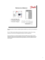
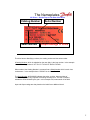
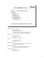
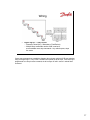
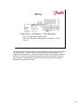
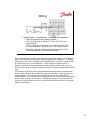
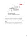
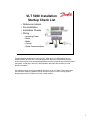
VLT 5000 Installation
Startup Check List
•
•
•
•
Reference material
Pre-Installation
Installation Checks
Wiring
–
–
–
–
–
Incoming Power
Motor
Brake
Control
Serial Communications
This presentation deals with the start-up of VLT 5000 drives. It is designed to help you
handle the start-up of the drive in normal applications. Because of the flexibility of these
drives, there may be some specialized applications that are not specifically covered by these
instructions. In that case, refer to the documentation that came with the drive for more
specific information.
This training module covers the installation and wiring of the VLT 5000. This section starts
with reference material, installation checks and then covers a number of wiring options.
Programming of the VLT 5000 is covers in another module.
1
! DANGER
Touching the electrical parts may be fatal — even after
the equipment has been disconnected from the AC line.
To be sure that the capacitors have fully discharged,
wait 15 minutes after power has been removed before
touching any internal component
Because the drive uses large electrolytic capacitors in its power circuitry, it can maintain a
dangerous voltage level for up to 15 minutes after power has been removed. Therefore,
always be sure that power has been removed from the drive for at least 15 minutes before
working with the power circuitry of the drive.
It is always wise to use a voltmeter to measure any potentially dangerous electrical circuit
before working on it.
2
Reference Material
• Instruction Manuals
• Connection Diagram
• Schematic Diagram
These three pieces of reference material might be available to you when you are starting up
a drive.
The VLT 5000 Instruction Manual provides general information on topics like mounting
clearances, drive fuses, terminal tightening torques, and drive parameters.
From the Customer, a Connection Diagram might be available which provides a sketch
indicating the layout and use the equipment in the system. A Schematic Diagram from the
customer could also provide details of the wiring between the drive, any options, and the
control system.
3
Hp to kW Chart
Model
5001
5002
5003
5004
5005
5006
5008
5011
5016
5022
5027
Hp
0.25
0.33
0.50
0.75
1.0
1.5
2.0
3.0
4.0
5.0
7.5
10.0
15.0
20.0
25.0
kW
0.18
0.25
0.37
0.55
0.75
1.1
1.5
2.2
3.0
4.0
5.5
7.5
11.0
15.0
18.5
Model
5032
5042
5052
5062
5075
5100
5125
5150
5200
5250
5300
5350
5450
5500
Hp
30.0
40.0
50.0
60.0
75.0
100.0
125.0
150.0
200.0
250.0
300.0
350.0
450.0
500.0
kW
22.0
30.0
37.0
45.0
55.0
75.0
90.0
110.0
132.0
160.0
200.0
250.0
315.0
355.0
• 1 Hp = 0.746kW
• Each VLT 5000 can be under sized by 4 and over
sized by 1 – but watch current limits.
• This chart shows most of the Parameter 102 settings
The drive takes all size information in kilowatts (kW), so horsepower (Hp) must be converted
to kW. The formula is 1 Hp = ¾ of a kW. The chart above shows the equivalent.
Each drive size can be programmed to accommodate 4 sizes smaller and one size larger.
On the larger size – do not exceed the maximum current rating of the drive.
Parameter 102 in the Instruction Manual shows all the kW sizes.
4
The Nameplates
All Drives – On the Top or Left Side of the Drive
Catalog Number
Sales Number
Serial Number
Output Ratings of Drive
The drive has two identifying numbers, the catalog number and the sales number.
A Catalog Number, which is explained on the next slide, is the long number. In the example
above the catalog number is VLT 5011-P-T2-CN1-ST-R0-DL-F00-A00.
When ordered, the Catalog Number is converted into a Sales Number which is much less
cumbersome. In the example above 178B3372 is the Sales Number.
The Serial Number, 805016H332 indicates the series, revision, place and date of
manufacturing, and is very important concerning warranty work. The last 3 numbers
indicate the week followed by the year. In this example 332, means week 33 of 2002.
Input and Output ratings are also placed on the label for an additional check.
5
Pre-Installation Check
Catalog Order Number System (Found on page D 62 of the catalog)
Example:
VLT- 5008–P-T5-B20–EB-R0–DL-F00-A00-C0
VLT: Series
5XXX: Model Number -------------|
P: Process Application -----------------|
AC Line Voltage -----------------------------|
T2: 3 phase 200 – 240 Vac
T5: 3 phase 380 – 500 Vac
T6: 3 phase 550 – 600 Vac
Enclosure (dimensions -page 39)-------------|
B20: Bookstyle Chassis (IP20)
C00: Compact Chassis (IP 00)
C20: Compact Protected Chassis (IP 20)
CN1: Compact NEMA 1 (IP 20)
C54: Compact NEMA 12 (IP 54)
• Compare AFD model number with what was ordered.
Hardware – EB
ST means Standard
SB means Standard with Brake
EB means Extended with brake (load-sharing) the 300500Hp have EX and DX which has a fuse disconnect
RFI Filter – R0
R0 means no extra filter
R1 adds 1A filter
R3 adds both 1A and 1B filter
Display – DL
DL means with LCP display
D0 is without the LCP
Fieldbus Option – F00
F00 = none; F10 = Profibus DP/FMS; F20 = Modbus +; F30 =
DeviceNet; F40 = LonWorks
Application Option – A00
A00 = none; A10 = Programmable Sync/Pos Card; A11 =
Synchronizing card; A12 = Positioning Card
Conformal Coating – C0
C0 means no coating
C1 has coating
6
Pre-Installation Check
• Be sure the Line Power, AFD and Motor have the same voltage
range
• Insure that all hand tools and kits are available.
Before installing the drive, check to be sure that the power line, the drive, and the motor are
all rated for the same voltage. It may be necessary to check the wiring inside the motor's
conduit box to confirm its voltage rating.
Options and kits:
Part numbers for Dynamic Brake Resistors, additional RFI Filters, LCP Remote mounting kit,
serial communication cards, application cards, additional relay cards, LC Filters and
Terminal Lug Kits are covered in the catalog.
7
Pre-Installation Check
• Record motor data information
–
–
–
–
–
Motor Power
Motor Voltage
Motor Frequency
Motor Current (FLA)
Motor Speed (RPM)
Write down the motor nameplate information. This will be important later during
programming. A conversion between HP and kW must be calculated 1Hp = 0.75kW.
In the example 20Hp = 15kW.
Motor Power = ___________________ kW
Motor Voltage = __________________ Vac
Motor Frequency =
50Hz
60Hz
Motor Current = __________________ Amps
Motor Speed = ___________________RPM
8
Pre-Installation Check
• Always ensure that Drive can handle maximum current
of the motor.
• Example page 20 – VLT 5100 – CT, HO
It is always important to check the technical data of the instruction manual for the drive you
are installing to certify that the drive is able to handle the maximum current of the motor. In
the example above a 100Hp (75kW) motor uses 125amps maximum current. The technical
data using the High Overload (150%) section and 460 V and VLT,N rating equals 130amp,
which means that it can handle this motor.
9
Pre-Installation Check
• Check Motor Wiring
– No power correction capacitors between drive and motor
– 2-speed motors must be wired for full speed
– Part-winding start motors, must be wired for run.
Insure that there are no power correction capacitors between the drive and the motor.
These types of capacitors must always be located on the incoming power to the drive, never
the output of the drive.
If you are using the drive on a 2-speed motor, always use the “run” wiring configuration,
never use the “start” wiring.
10
Installation Checks
• Fuses must be installed
– Sized using Pages 34-35 in Instruction Manual
To comply with UL / cUL, fuses must be wired on the incoming power side of the drive. The
types of fuses are shown in the technical data section of the instruction manual. In the
example above fuses and a disconnect switch are diagramed. To comply with UL never wire
the drive to circuit breakers because they do not trip as fast as fuses.
11
Installation Checks
• Environmental Concerns
– Clean and Dry
– 24-Hour temperature limit – page 214
– Altitude Limits – page 214
The VLT 5000 can be supplied with a NEMA 1(IP 20) or NEMA 12(IP 54) enclosure. These
enclosures provides some degree of protection from falling dust. Therefore, drives with a
NEMA 1(IP 20) and 12(IP 54) enclosures should be mounted indoors in a relatively clean
and dry location.
Because the drive relies on the ambient air for cooling, it is important to observe the
limitations on ambient air temperature and elevation. Contact the Service Department if you
think that the mounting location of the drive compromises its ability to provide long term,
reliable operation. Charts for temperature and elevation are found near the back of the
instruction manual in the “List of Functions” section.
Temperature equivalents
Heights equivalents
30°C = 86°F
1kM = 3300 feet
35°C = 95°F
2kM = 6600 feet
40°C = 104°F
3kM = 10,000 feet
45°C = 113°F
Enclosure equivalents
50°C = 122°F
IP 00 = chassis
55°C = 131°F
IP 20, 21 = NEMA 1
60°C = 140°F
IP 54 = NEMA 12
65°C = 149°F
IP 65 = NEMA 4
12
Installation Checks
• Mounting
– Vertical
– Flush Mounted Only
In order to provide proper cooling, the drive must always be mounted vertically.
It is also important to establish a "chimney" around the drive's heat sink to ensure that all
cooling air passes along the entire length of the heat sink. If a drive with no option panel is
not mounted directly to a vertical flat surface, it is important to see if this leaves any heat sink
fins exposed in the back. If it does, a flat plate must be mounted to the back of the drive to
ensure proper cooling.
Drives that include a bypass or other option enclosure are generally factory-mounted to a
back plate. Therefore, this is not a concern with such drives.
13
Installation Checks
• Mounting
– Side by Side is acceptable
– Needs space above and below drive
The VLT 5000 cools itself by drawing cooling air through the bottom of its enclosure and
exhausting it out the top. It is therefore important to provide enough space above and below
the drive to ensure proper flow of cooling air. To determine the necessary clearances, see
the “installation” section of the Instruction Manual, pages 43-44. The smallest drive requires
4” (10cm) on the top and bottom, nothing on the sides. This top and bottom space goes
from 4”, to 9” (10-22.5cm) on smaller units, then 16” (40cm) on the largest drive which is on
the top only. All drives can be mounted side by side.
14
Mounting the Drive
• Keep the drive clean
– Use dust covers to keep construction dust from
getting into it
– Remove the dust covers before applying power
If construction work continues after the drive is mounted, it is important to keep the drive as
free as possible from concrete dust and similar dirt. If the drive does not have power applied
to it, it should be kept covered. If the drive must be powered up and run, this cover must be
removed. It is still important to ensure that the drive stays as clean as possible. It may be
necessary to clean the interior of the drive once construction is completed.
15
Wiring the Drive
•
•
•
•
•
•
General Wiring
Power Input
Brake
Motor Output
Control
Serial Comms
This next section covers the wiring of the drive. The first area to be covered is general
wiring practices. The other sections cover power or line wiring from the drive to incoming
power, brake wiring. The motor wiring covers the connections between the drive and the
motor. Control wiring for Digital Inputs/Outputs and Analog Input/Outputs are also covered.
The last section covers the wiring for serial communications.
16
Wiring the Drive
• Conduit entry
– All wiring enters the bottom of drive
– Knock-outs are provided on many drives
– Larger drives have a removable conduit entry or
gland plate
General Practices
Most smaller drives have knock-outs for conduit entry. Larger drives provide a removable
conduit entry plate. It is important to remove this plate before drilling or punching it.
When a drive is supplied with an auxiliary enclosure, it generally is necessary to drill or
punch conduit entry holes in the auxiliary enclosure. It is important to ensure that metal chips
or filings don't get into any of the devices which are housed in the auxiliary enclosure.
17
Wiring the Drive
•
•
At least three separate METALLIC conduits must be connected
to the drive
– Power into the drive [L1, L2, L3 and a ground back to the
distribution panel]
– Power from the drive to the motor [U, V, W, and PE (power
earth ground)]
– Control wiring
A dedicated ground wire is needed
At least three separate conduits must be connected to the drive. One is for the incoming
power wiring, one is for the power wiring between the drive and the controlled motor, and the
third is for the control wiring.
Because the wiring from the drive to the motor carries high frequency electrical pulses, it is
important to be sure that no other wires are run in this conduit. If the incoming power wiring
is run in the same conduit as the motor wiring, these pulses can couple electrical noise back
onto the building's power grid.
Control wiring should always be isolated from the high voltage input power wiring to the
drive or the high voltage output power wiring from the drive to the motor.
18
Wiring the Drive
• Input fuses
– All drives must have input fuses installed in the
power supply to the drive
– Refer to the Instruction Manual for fuse sizing
In order to fulfill the requirements of Underwriters Laboratory (UL) as was stated on page 11,
all drives must be provided with fast-acting input power line fuses. The proper style and
rating for these fuses is specified in the Instruction Manual on page 24.
19
Wiring
• General Information
– Maximum voltage to control card is 24Vdc
– Do NOT connect 120/240/460/575 to Control
terminals
– Use Relay 01, 02, 03 for 120 or 240Vac
The maximum voltage for the control circuit must not exceed 24Vdc. A separate relay
terminal 01, 02, 03 is used for higher voltages, 120/240 Vac.
20
Wiring
• Motor Wiring
– Use Terminals 96, 97, 98
– Check torque – page 53
– Distance limits – Disconnect OK
A disconnect switch between the drive and motor may be required to meet electrical codes.
During operation if the disconnect switch is opened, no harm is done to the drive or motor. If
the disconnect is then closed and the drive is running, the motor may attempt to draw locked
rotor current from the drive. This may cause the drive to shut down on an over-current fault
trip. In order to avoid such a nuisance trip, it is best to wire an auxiliary contact from the
disconnect switch back to the drive's start circuit. Then, if the disconnect is opened while the
drive is running, the drive immediately shuts off. When the disconnect switch is closed, the
drive begins from a stop and smoothly accelerates the motor to the desired speed.
The maximum cable distance between the drive and motor for unshielded cable is set for
300m (1000 feet). If multiple motors are wired to one drive, the total distance from the drive
to all the motors does not exceed 300m (1000 feet).
If shielded cable is used as pictured above, the distance is dropped to 150m (500 feet). The
wires in the shielded cable are more compressed, which means that the capacitance
between the cable and ground is increased. A shorter distance is therefore needed for
proper operation.
21
Wiring
• Brake Wiring on SB & EB units
– Use Terminals 88 & 89 for resistor
– Load sharing for EB units
– External 24Vdc.
On Standard with Brake (SB) units there is an extra terminal labeled R – (81) and R + (82).
The dynamic brake resistor is wired to these 2 terminals. Brake resistors come separately
and are sized using a centrifuge as a model. If over a 2-minute window the dynamic brake is
used infrequently, less than 12 seconds, then a 10% brake resistor is adequate. If over a 2minute window the dynamic brake resistor is used a considerable amount of time, 48
seconds, then a 40% brake resistor is used.
On Extended with Brake (EB) units there is an additional terminal block added to the R-, R+
terminals. This terminal block has - DC (88) and + DC (89) which allows one drive to share
its generated power with another drive or drives that requires power.
With the EB unit there is another set of terminals labeled –24 Vdc, Common (35) and +24
Vdc (36) this allows the control card to remain active when main power to the drive is turned
off. This is important for 2 reasons:
1. when using the brake resistor to quickly discharge the DC Link capacitors.
2. When maintaining serial communications.
22
Wiring
• Control Wiring
–
–
–
–
Digital Inputs
Analog Inputs
Analog Output
Digital/Relay Outputs
This next section covers control wiring.
It covers Digital Input Wiring first, followed by Analog Inputs. Analog Outputs are covered
followed by Digital Outputs then Relay Outputs. It is always best to have control wiring in a
separate conduit away from power wiring.
23
Wiring
• Digital Inputs – 12 to 27 Enable
– Jumper terminal 12 (+24Vdc) to terminal 27 (enable command)
– Without jumper, bottom line of the display reads, “UNIT
READY” and it does not operate the motor. When this jumper
is made, the bottom line reads, “STANDBY”.
In its default state, the way it comes from the factory, a jumper or a connection is required for
operation. It must be connected between terminals 12 (24Vdc) and 27 (Digital Input), which
defaults to a “coasting stop inverse” command. If terminal 27 does not see 24Vdc, the drive
is not enabled and it does not operate. A display on the front of the drive gives a clear
indication when this occurs. After pressing the “Display/ Status” key, the bottom line reads,
“UNIT READY”. When ever this display is seen, a connection between terminals 12 and 27
is missing. Once this connection is made, the bottom line changes to read, “STANDBY”.
Digital Input Wiring covers the following:
Push-Button Switch
NO; NC; Multiple Offs, 3-wire S/S; Changing Reference
Continuous Switch (SPDT)
2-wire S/S; Start for Multiple Drives; SPDT Center-Off
Preset Speeds
Changing Setups
Encoders
24
Wiring
• Digital Inputs – Push button
–
–
–
–
Normally Open - Momentary
Functions: Latched Start (terminal 18 only)
Reset
Jog
Push-Button (PB) Switch – Normally Open (NO)
Some options:
Latched Start can be configured using terminal 18 only.
Reset can be accomplished from a remote location when the drive trips.
Jog can also be accomplished with a push-button NO switch. The Jog
frequency is set by parameter 213 and the ramp to the jog frequency
is set by parameter 211.
Note that the opposite side of the switch goes to terminal 12 which is a source of +24Vdc.
When the PB is pressed, and +24V is seen at the Digital Input, the programmed command,
such as Jog, is activated. When the PB is released and 0Vdc is seen at the Digital Input the
command is removed.
Jog Command is set in Parameter 305 for terminal 29.
+24Vdc seen at terminal 29 = AFD goes to Jog frequency.
0Vdc seen at terminal 29 = No jog for AFD.
25
Wiring
• Digital Inputs – Push Button
– Normally Closed - Momentary
– Stop Inverse means loss of 24Vdc to that terminal, stops the
motor.
– If multiple “stop” commands are required, additional terminals
(16, 17, 27, 29, 32 and 33) can be wired in parallel each
programmed for “Stop Inverse”.
Push-Button Switch – Normally Closed (NC)
Some options:
Normally closed switch is programmed for “Stop Inverse”. Inverse means that the
command, “Stop” is given when 24Vdc is gone.
Stop Command is set in Parameter 300 for terminal 16.
Because of the Inverse command:
+24Vdc seen at terminal 16 = AFD does not see stop command.
0Vdc seen at terminal 29 = AFD stops.
If multiple Stop commands are needed a total of 6 Digital Inputs can be programmed for
Stop Inverse.
26
Wiring
• Digital Inputs – Push Button
– Normally Closed (NC) - Momentary (Push Button)
– Multiple stop commands can be wired in series to
accommodate more stop commands. Any switch opens, stops
the motor.
If more stop commands are needed the diagram above shows multiple NC PB stop switches
using one Digital Input. If any of the 5 switches are opened the drive stops. With each input
programmed as a Stop Inverse command, the drive stays off until it sees a “Latched Start”
command.
27
Wiring
• Digital Inputs – Pushbuttons - 3 Wire Start/Stop
– Term. 18 (P 302) set to “Latched Start”
– Term. 16 (P 300) set to “Stop Inverse” for terminal 17, 27, 29,
32 or 33.
The diagram above shows the wiring for a 3-wire Start/Stop. Power comes from terminal 12,
a source of +24Vdc. Terminal 18 is programmed for Latched Start and terminal 16 is
programmed for Stop Inverse. When the NC PB stop switch is closed, sending +24Vdc to
terminal 16, then terminal 18 can be pressed sending +24Vdc into terminal 18 giving it a
start command. A latched signal continues to run the drive until the NC PB is opened,
sending a stop command to the drive.
28
Wiring
• Digital Inputs – Pushbuttons - Changing the Reference
– Pulsed Increase/Decrease Reference Speed
– Term. 32 (P 306) set to “Speed UP”; Term. 33 (P 307) set to
“Speed DOWN”
– Term. 17 defaults to “Freeze Ref.” or on newer units set P 330
to “Freeze Reference” saving terminal 17 for another function.
– Sensitivity of buttons is determined by values placed in P 209
for increase speed & P 210 for decrease speed.
Here is the a diagram for using 2 Digital Inputs as a push button reference. In the example
above a NO PB is wired to terminal 32, which is programmed for “Speed UP”. A NO PB is
wired to terminal 33, which is programmed for Speed DOWN” Terminal 17 is wired directly
to +24Vdc and is set to “Freeze Reference”. In later revisions of software there is a
parameter 330 which can be programmed for freeze reference without using terminal 17.
There must be a freeze reference command in order for the speed up and speed down PB to
work.
The sensitivity of the PB to speed up and speed down are determined by parameters 209
(Ramp 2 up) for speed up and 210 (Ramp 2 Down) for speed down. The time value set in
these parameters is the hold down time it takes to go from minimum speed (0Hz) to
maximum (60Hz). If 1 second is used then holding the PB for 1 second moves the reference
from 0 to 60Hz, making is very sensitive. It is better that a value of 12 seconds be placed
here, which moves the reference from 0 to 60Hz when the PB is held down for 12 seconds,
making it less sensitive.
29
Wiring
• Digital Inputs – Continuous
–
–
–
–
Single-pole, double throw (SPDT)
2-wire Start/Stop using term 18.
Reverse using term 19 (P 303) – P 200 set to Both Directions
Other functions: Quick Stop, Direction Change, Ramp 2
Continuous Switch
This diagram shows a 2-wire Start/Stop using terminal 18 which is programmed for Start.
When the switch is ON, the drive starts. When the switch is OFF the drive stops. The
switch wired to terminal 19 determines direction when the drive is ON. With 0Vdc going to
terminal 19, programmed for Reversing, the drive goes forward. When +24Vdc goes into
terminal 19, the drive goes backward, assuming that parameter 200 has been set to “Both
Directions”.
Continuous switches can also be used for a number of other different functions, such as
Quick Stop, Ramp 2, Clockwise only, jog, preset speeds, changing setups and safety
interlock. For more information see the chart right before parameter 300 in the VLT 5000
instruction manual.
30
Wiring
• Digital Inputs
– Multiple Starts from One command
– Common connected, terminal 20, on each unit
– Maximum of 200mV
In the example above, one switch is used to start multiple drives. The +24Vdc from the first
drive is being sent to the other drives. Notice that a wire most be connected between all the
Digital Input commons, terminal 20. There is a maximum of 200mV coming from the power
supply of the first drive, which limits the number of drives that may be started.
31
Wiring
• Digital Inputs – One switch ON/OFF and Direction
– SPDT Center OFF
– Terminal 18 (P 302) set for “Start”
– Terminal 19 (P 303) set for “Start & Reverse”
Single Pole Double Throw with Center OFF.
This switch is used to start the drive in either direction, and turn it OFF in the center position.
Notice that +24Vdc from terminal 12 goes to the center of the switch. When the switch is
completed to terminal 18 is goes Forward. When the switch goes to terminal 19, which is
programmed for Start & Reverse, the drive goes in the opposite direct, backwards, assuming
that parameter 200 has been changed to “Both Directions”.
32
Wiring
• Digital Inputs – Preset Speeds
–
–
–
–
4 Preset Speeds set in Parameters 215, 216, 217 and 218
4-Position Switch using diodes for signal isolation
Parameter 214 is set to “External/Preset”
For additional presets up to maximum of 16, change between
setups and presets.
4-Position Rotary switch for Preset Speeds
In the diagram above terminal 16, programmed for “Preset Reference” turns the
preset speeds ON or OFF. This assumes that parameter 214 has been set to
“External/Preset”. Once terminal 16 sees +24Vdc, the preset speeds are enabled.
Terminals 32 and 33 are used to determine the actual preset speed. Terminal 32 is
programmed as “Preset reference LSB” (least significant bit). As the binary chart shows
above, this is the column on the right. Terminal 33 is programmed as “Preset Reference
MSB” (Most Significant Bit). This is the column to the left. According to this chart when both
terminals 32 and 33 see 0Vdc, the preset speed follows the value placed in parameter 215.
So when the 4-position rotary switch is in position #1, parameter 215 is the reference. In
position 2, terminal 32 sees +24Vdc (1) and terminal 33 sees 0Vdc (0), which places the
value in parameter 216 as the reference. The rest of the chart above explains parameter
217 and 218.
In the wiring diagram above, 2 diodes attached to terminals 32 and 33 and to switch
position 4 prohibit current from flowing between 32 and 33 when position 2 or 3 are used. A
diode type 1N4004 is used in this application. Notice that the banded end (+) of the diode is
attached to terminal 32 and 33.
Terminals 16 and 17 could also be used to select different preset speeds. These
terminals 16 & 17 or 32 & 33 could also be used to select different setups. Terminal 29 could
also be used if one of these terminals were already used. It is possible using 16 and 17 for
preset speeds and terminals 32 and 33 for different setups to have a maximum of 4 different
presets speeds with 4 different setups or 16 different preset speeds.
33
Wiring
• Digital Inputs
– Changing Setups
– 4-Position Switch and relay used for signal isolation
– P 004 must be set to Multi Setup
4-position with a relay for Changing Setups
In the diagram above a 4-position switch is used to shift between 4 different program
setups. Notice the binary chart for setups # 1 through # 4. In order for the setup change to
work, parameter 004 must be set for “Multi Setup”. A DPDT (double-pole double-throw)
relay is used when position 4 is selected. This is another way, besides diodes seen in the
last example, to keep feedback power from terminals 32 and 33. To complete the circuit for
the 24Vdc (terminal 12) relay one side of the relay is attached to terminal 39 (common for
power).
34
Wiring
• Digital Inputs – Encoder
–
–
–
–
–
A Channel showing speed comes into term 33 (P 307)
B Channel showing direction comes into term 32 (P 306)
+24Vdc power from terminal 13, common terminal 39
P 329 sets PPR for Encoder
P 345 sets loss timeout, P 346 sets loss function
Encoder
For a Speed Closed Loop application, the encoder is wired directly into the control
section. Terminal 33 is set for the A channel, which indicates speed, and terminal 32 is set
for the B channel, which is 90° out of phase and indicates direction. +24Vdc Power for the
encoder comes from terminals 12 or 13, and common is wired to terminal 39. Only terminals
33 and 32 can be wired for an encoder. This arrangement must use +24Vdc, 5Vdc used on
many encoders does not operate indicate a signal to the drive.
Parameter 329 sets the pulse per revolution, PPR, for the encoder, from 128ppr up
to 4096ppr. By default it goes to 1024ppr. Parameter 345 sets the amount of time (0-60sec)
the drive is to wait before it indicates that the encoder has lost its signal and that there is an
error. Parameter 346 indicates what the drive does upon a loss of the encoder signal. By
default it goes to OFF.
The next section covers Analog Inputs.
35
Wiring
• Analog Inputs – 0 to 10Vdc
–
–
–
–
Potentiometer
Term 53 (P 308) set to “Reference” by default
Term 54 (P 311) set to “No operation” by default
Term 50 is +10Vdc; Term 55 is common
Analog Input – potentiometer.
A potentiometer or pot (typically 1K ohm) can be used to give a remote reference to
the drive. One side of the pot is wired to terminal 50 a source of +10Vdc. The other side of
the pot is wired to terminal 55, which is the Analog Input common. The middle tap is wired
to terminal 53, terminal 54 if a second pot is used. Parameter 309, minimum (0Vdc) and
310, maximum (10Vdc) sets the usable voltages, max range 0 to 10Vdc. Parameter 308
sets the function for terminal 53, by default Reference. See the VLT 5000 Instruction manual
for other options. This pot operates the reference, only if parameter 002 is set to Remote.
For terminal 54, parameter 311 sets its function which is defaulted to “No
Operation”. Parameter 312, minimum (0Vdc) and 313, maximum (10Vdc) set the usable
voltage range.
36
Wiring
• Analog Inputs
– Potentiometer
– P 203 is Min – Max or –Max to +Max
– P 215 sets offset, may be negative
In the diagram to the left, parameters are indicated to show the relationship between
the signal coming from the pot and the reference. The signal from the pot is indicated on the
left of the graph. Notice that parameters 309 and 310 set the voltage range. Parameter 308
sets the function for this signal, in this case the reference.
On the bottom, the reference is indicated. Parameters 204, minimum (0Hz) and
parameter 205, maximum (60Hz) set the speeds if parameter 100 is set to Speed Open
Loop. In the diagram above the reference is indicated in %, which is one of the displays
readable from the LCP, Reference [%]. Notice that parameter 203 is set to Min – Max.
Parameter 214 is set to Sum and parameter 215 is set to 0%. This arrangement is used
frequently.
The pot however, can be setup to give a negative reference which causes the drive
to go in reverse if programmed correctly. Observe the graph to the right. It is not possible to
change the minimum reference, parameter 204 to a negative number, but a negative number
can be added to the minimum by using parameter 214 set for Sum and parameter 215 set to
–50%. This shifts the reference from 0 to 100% to –50 to +50%. Parameter 203 must be set
to –max to +max and parameter 200 must be set to Both Directions in order for this to work.
Now when 0Vdc comes in from the pot the reference goes to –50% and when the pot goes
to 10Vdc the reference goes to +50%. The maximum reference, parameter 205 must be
have a value that covers the complete range from –max to + max. Example: To make the
speed go from –50Hz to +50Hz and value of 100Hz must be placed in parameter 205.
When the voltage coming from pot reaches 5Vdc it might oscillate between forward
and reverse. Parameter 123 can be set to give a deadband around 5Vdc. In the example
above 3Hz might be selected, which means that the drive goes for 50Hz forward down to
3Hz, stops, the goes reverse from 3Hz back up to 50Hz.
37
Wiring
• Analog Inputs
– One Potentiometer feeds multiple drives
One Pot controlling multiple drives
In the example above, one potentiometer is used to send a 0-10Vdc reference to the
top drive. To send this same reference signal to the next drive, terminals 53 are wired
together and terminals 55 (AI common) are wired together.
38
Wiring
• Analog Inputs
– 2-wire Transmitter
– Term 12 or 13 supplies power +24Vdc
– Jumper 39 to 55 to connect commons
Analog Input – 2-wire Transmitter
The picture above shows a 2-wire 4-20mA current transmitter. This type of
transmitter requires power from the drive. The positive side of the transmitter is wired to
terminal 12 or 13(+24Vdc). Terminal 39 (common for power) must be wired to terminal 55
(common for the Analog Inputs). The negative side of the transmitter is wired to terminal 60
to complete the circuit.
Parameter 314 is setup for Feedback, with parameter 315 setting the minimum
(4mA) and parameter 316 setting the maximum (20mA). If the transmitter goes to 0mA,
parameter 317 sets the timeout, default is 10sec, and parameter 318 sets the function if the
transmitter goes.
The range of the transmitter is set in parameter 414, minimum feedback, and set in
parameter 415, maximum feedback. Parameter 416 sets the engineering units for the
transmitter, from a list of 40 items.
39
Wiring
• Analog Inputs
–
–
–
–
3-wire Transmitter
Term 12 or 13 supplies power +24Vdc
Transmitter’s Signal wired to terminal 60 (P 314 = Feedback).
Jumper 39 to 55 to connect commons
Analog Input – 3-wire Transmitter
The picture above shows a 3-wire 4-20mA current transmitter. This type of
transmitter also requires power from the drive. Terminal 12 on the drive sends power to the
transmitter labeled +24Vdc. A common terminal on the transmitter is wired back to terminal
39 (common for power) on the drive. The signal from the transmitter is wired to terminal 60
(mA input) on the drive. There must be a connection between terminal 55 (AI common) and
terminal 39, in order for the signal to work.
Parameter 314 is setup for Feedback, with parameter 315 setting the minimum
(4mA) and parameter 316 setting the maximum (20mA). If the transmitter goes to 0mA,
parameter 317 sets the timeout, default is 10sec, and parameter 318 sets the function if the
transmitter goes.
The range of the transmitter is set in parameter 414, minimum feedback, and set in
parameter 415, maximum feedback. Parameter 416 sets the engineering units for the
transmitter, from a list of 40 items.
Next is Analog Outputs.
40
Wiring
• Analog Outputs
–
–
–
–
Meter Indication
Terminal 42 and 45 set to AO or DO
If using 0-Fmax 0-20mA, meter trim is P 202.
New software – meter trim – use P 357 – 360.
Analog Outputs
The current meter shown above has its positive terminal wired to terminal 42 of the
drive and the negative terminal wired to terminal 39. Terminal 45 can also be used for meter
indication. Parameter 319 sets the display for terminal 42 (default is 0 to Imax, current) and
parameter 321 sets the display for terminal 45 (default is 0 to Fmax, frequency). Each AO
option has 3 output selections, 0-20mA; 4-20mA or 0-32,000 pulses. If 0-Fmax is used for
terminal 45, the meter can be trimmed by adjusting parameter 202. By default parameter
202 is set to 132Hz, which means that the output reaches 20mA when the drive frequency
reaches 132Hz. If parameter 202 is changed to 60Hz, the meter reaches 20mA when the
drive frequency reaches 60Hz.
In the latest software revisions, parameters 357 sets the output minimum scaling on
terminal 42 and parameter 358 sets the output maximum scaling. Parameter 359 sets the
output minimum scaling on terminal 45 and parameter 360 sets the output maximum scaling.
41
Wiring
• Analog Outputs
– Master/Slave (Leader/Follower)
– AO of Master to AI of Slave
– Use 0-Fmax 4-20mA, use P 202 on master to match slope.
– Use P 215 on slave to match intercept.
Analog Output – Master/Slave
If 2 drives are to work together, at the same frequency, a master/slave
(leader/follower) setup is of benefit. In the diagram above, the Analog Output from the
master is wired to the analog input of the slave. Terminal 42 of the master is wired to
terminal 60 of the slave. Notice that commons must be attached, terminal 39 of the master
to terminal 55 of the slave. Parameter 202 in the master sets the slope of the signal and
parameter 215 in the slave sets the intercept. In later versions parameters 357, terminal 42
minimum scaling, and parameter 358, terminal 42 maximum scaling, are used. These last 2
parameters can only be programmed with the drive stopped which requires more time for
fine tuning. The accuracy of this arrangement has a maximum error of 0.3 Hz any where
from 3 to 60Hz.
42
Wiring
• Analog Output - Pulse
– Master/Slave (Leader/Follower)
– DO of Master to DI of Slave set for Pulsed Reference
– Use 0-Fmax 0-32,000 pulses, set max pulses to 32,000 use P
202 on master to match slope.
– Use P 215 on slave to match intercept.
Analog Output – Pulse
The diagram above shows another way to connect 2 drives together in a
Master/Slave (Leader/Follower) arrangement. This arrangement acts like an encoder and is
slightly more accurate, perhaps 0.2Hz being the maximum error over the 3 to 60Hz range.
In the diagram above, the pulsed reference signal, terminal 42 from the master drive
(1) is connected to a digital input terminal 17 of the slave drive (2). Terminal 17 or 29 can be
used, but it must be programmed for “Pulse Reference”. The common terminal 39 from the
master is attached to the common of the slave terminal 20. The square wave attached to
terminal 42 is used to indicate a pulsed output.
Parameter 319 in the master is set to “0-Fmax = 0-32000p”. Parameter 320 sets the
number of pulses, which is more accurate if increased to 32000. The slave in parameter 327
must have its pulses set to 32000, the same number placed in p 320 of the master. Ratios
may be set using these 2 parameters. Example: 2:1 ratio can be set up with 32000 set in p
320 in the master and 16000 set in p 327 in the slave.
43
Wiring
• Digital/Relay Outputs
– Digital Output powered +24Vdc
– Relay Outputs are dry (no power) contacts
Digital Outputs
Terminals 42 and 45 besides being used as Analog Outputs can also be used as
Digital Outputs. Digital Outputs are always +24Vdc powered 2-state outputs. In the diagram
to the left a 24Vdc light is wired directly to terminals 42 (DO signal) and 39 (common).
There is a chart in the VLT 5000 Instruction manual right before parameter 319, that explains
the 35 different options for a Digital Output. As an example, in the diagram above, the light
comes on when the drive goes in reverse.
Relay Outputs
Relay Outputs have the same 35 options as the Digital Outputs but without any
power, they are “dry” contacts. There are 2 relays in the VLT 5000. The most commonly
used relay is referred to as Relay 1, because it uses terminals 01 (common), 02 (NO), and
03 (NC). These terminals are not on the control card but on the AC side of the drive.
Because they are dry contacts, 24Vac, 120Vac or 240Vac (max of 2 amps) power can go
through the relay to energize a coil, as diagramed on the right. parameters 324 ON delay,
and parameter 325 OFF delay, give the ability to delay switching up to 600 seconds.
The other Relay, referred to as Relay 4 uses terminals 04 (common) and terminal 05
(NO), which is on the control card. This limits the power that can go through this relay to a
maximum of 50Vac and 1 amp. There are no parameters for switching delays on Relay 4.
44
Wiring
• Serial Communications
– Need repeater (amplifier) after 31 drives attached together
– Dip switch settings 2 & 3 to OFF except for 2 bus ends
Serial Communications
This diagram shows how the serial communications is wired. Notice that it is an RS485 connection, which means that all the positive terminals (68) are wired together and all
the negatives (69) are wired together. These connections must be in a “Daisy Chain”
fashion which only has 2 ends. Star configurations should NOT be used. The address for
each drive is set in parameter 500, from address 1 to 126. The default address is #1. If
more than 31 drives are attached a repeater should be used to amplify the signal.
On the control card just above the serial communications plug, there is a DIP switch,
which is used to enable/disable the EOL (end of line) resistor. If one or 2 drives are attached
together, leave the DIP alone. Once a 3rd drive is added, the middle drive must have
switches 2 and 3 turned OFF, down, to remove the EOL resistor. If other drives are added,
all drive that are not on the 2 ends must have DIP switch settings 2 and 3 turned OFF.
45