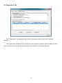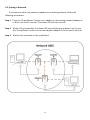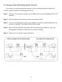
1
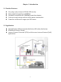
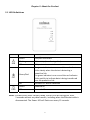
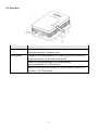
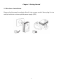
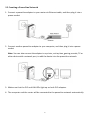
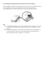
 HP-5101
User Manual
08-2012 / v1.1
0 COPYRIGHT Copyright © Edimax Technology Co., Ltd. all rights reserved. No part of this publication may be reproduced, transmitted, transcribed, stored in a retrieval system, or translated into any language or computer language, in any form or by any means, electronic, mechanical, magnetic, optical, chemical, manual or otherwise, without the prior written permission from Edimax Technology Co., Ltd. Edimax Technology Co., Ltd. makes no representations or warranties, either expressed or implied, with respect to the contents hereof and specifically disclaims any warranties, merchantability, or fitness for any particular purpose. Any software described in this manual is sold or licensed as is. Should the programs prove defective following their purchase, the buyer (and not this company, its distributor, or its dealer) assumes the entire cost of all necessary servicing, repair, and any incidental or consequential damages resulting from any defect in the software. Edimax Technology Co., Ltd. reserves the right to revise this publication and to make changes from time to time in the contents hereof without the obligation to notify any person of such revision or changes. The product you have purchased and the setup screen may appear slightly different from those shown in this QIG. For more information about this product, please refer to the user manual on the CD‐ROM. The software and specifications are subject to change without notice. Please visit our website www.edimax.com for updates. All brand and product names mentioned in this manual are trademarks and/or registered trademarks of their respective holders. Edimax Technology Co., Ltd. Add: No. 3, Wu‐Chuan 3rd Rd., Wu‐Ku Industrial Park, New Taipei City, Taiwan Tel: +886‐2‐77396888 Email: [email protected] Contents Chapter 1: Introduction ..................................................................................................................................... 1 1.1 Product Features .................................................................................................................................. 1 1.2 Application ........................................................................................................................................... 1 1.3 Compatibility ........................................................................................................................................ 2 1.4 System Requirements .......................................................................................................................... 2 Chapter 2: About the Product ............................................................................................................................ 3 2.1 LED Definitions ..................................................................................................................................... 3 2.2 Interface ............................................................................................................................................... 4 Chapter 3: Getting Started ................................................................................................................................. 5 3.1 Hardware Installation .......................................................................................................................... 5 3.2 Creating a Powerline Network ............................................................................................................. 6 3.3 Creating an Encrypted Powerline Network with Two Adapters .......................................................... 7 Chapter 4: Utility Software Installation ............................................................................................................. 8 Chapter 5: Using the Utility Software .............................................................................................................. 14 5.1 Main Tab ............................................................................................................................................ 14 5.2 Privacy Tab ......................................................................................................................................... 17 5.3 Diagnostics Tab .................................................................................................................................. 19 5.4 About Tab ........................................................................................................................................... 20 Chapter 6: Powerline Network Management with Group Button .................................................................. 21 6.1 Forming a HomePlug AV Logical Network ......................................................................................... 21 6.2 Joining a Network .............................................................................................................................. 22 6.3 Leaving a Network & Joining another Network ................................................................................. 23 Chapter 7: Troubleshooting ............................................................................................................................. 24 Chapter 1: Introduction 1.1 Product Features z Easy plug‐n‐play setup and 128‐bit AES security z Max. powerline speed up to 500Mbps z Backward compatible with 200Mbps powerline adapters z Features energy saving mode to reduce power consumption z Powerline transmission range up to 300 meters 1.2 Application z High‐definition (HD) and standard‐definition (SD) video distribution z Broadband Internet sharing z Internet Protocol Television (IPTV) and Voice over Internet Protocol (VoIP) applications 1 1.3 Compatibility 200Mbps (Edimax HP‐200x series) and 500Mbps (Edimax HP‐500x series) powerline adapters are able to communicate directly with one another. 200Mbps and 500Mbps powerline adapters can be used on the same household electric wiring as 14Mbps & 85Mbps powerline adapters (Edimax HP‐85XX series) without interfering, but are not able to communicate directly with 14Mbps and 85Mbps powerline adapters. 1.4 System Requirements z Computer with Ethernet port running Windows XP/Vista/7, Linux, MAC OS X and any other operating system. z Any connected devices must feature a network port. z Utility software supports Windows XP/Vista/7. 2 Chapter 2: About the Product 2.1 LED Definitions LED LAN PLC PWR Status Description
Green LAN port connected
Blinking LAN activity (transferring data)
Off LAN port not connected
Green/Red The green indicator turns on and the red indicator blinks slowly when the device is detecting a powerline link. The green indicator turns on and the red indicator blinks quickly to indicate data is being transferred over the powerline link.
Off No other PLC device detected
Green Powered on
Off Powered off
Note: The device will enter standby mode, and all LEDs will extinguish, after 5 seconds without any data transfer, including when the Ethernet cable is disconnected. The Power LED will flash once every 15 seconds. 3 2.2 Interface Interface Description Ethernet Port This is a Fast Ethernet port for connecting to a computer or other devices with a network port.
Group/Reset Creates an encrypted powerline network group automatically (press the button for less than 3 seconds).
Leaves an encrypted powerline network group (press the button for 5~8 seconds).
Restores the powerline adapter to factory defaults (press the button for 10~15 seconds).
4 Chapter 3: Getting Started 3.1 Hardware Installation Always plug the powerline adapter directly into a power socket. Never plug it into a multiple socket or uninterruptible power supply (UPS). 5 3.2 Creating a Powerline Network 1. Connect a powerline adapter to your router via Ethernet cable, and then plug it into a power socket. 2. Connect another powerline adapter to your computer, and then plug it into a power socket. Note: You can also connect the adapter to a printer, set top box, gaming console, TV or other device with a network port, to add the device into the powerline network. 3. Make sure that the PLC and LAN LEDs light up on both PLC adapters. 4. The computer and the router will be connected to the powerline network automatically. 6 3.3 Creating an Encrypted Powerline Network with Two Adapters Once both adapters have been successfully connected, press the “Group/Reset” button of each adapter for less than 3 seconds within 2 minutes. The adapters will automatically generate a random password to encrypt the powerline network. Note: z To add additional adapters into the encrypted powerline network or to remove an adapter from the powerline network, please refer to the Chapter 6 in the manual z If the powerline adapter in your network does not feature a “Group/Reset” or an “Encrypt” button, you can use the utility software as an alternative. For more details please refer to Chapter 5 in the manual.
7 Chapter 4: Utility Software Installation You can manage all the connected powerline adapters with the utility software. Only install the utility software when you need to add other powerline adapters without “Group” or “Encrypt” button. Step 1 Before installing the utility software, make sure that no other powerline utility is installed on your computer. If any other utility software is installed, uninstall it and reboot the computer. Step 2 Insert the CD into your CD‐ROM drive. When the following “Autorun Wizard” appears, select your model. Note: If autoplay is installed on your computer, the “Autorun Wizard” will start automatically. Otherwise, please go to Autorun folder in the CD and execute the “AutoRun.exe” program. 8 Step 3 Then click “Setup Utility”. Step 4 If you have not installed WinPcap version 4.1.2 (or higher) on your computer before, please click “OK” to install the utility. The wizard will guide you through the setup process. 9 10 Step 5 When the “Edimax PowerLine Utility” setup wizard appears, click “Next” to continue. 11 Step 6 In the “License Agreement” screen, please select “I Agree” and then click “Next” to continue. Step 7 Select where you want to install the utility software, and then click “Next”. 12 Step 8 If you confirm to install the utility, click “Next”. Step 9 After the installation is complete, click “Close”. Step 10 An icon will appear on your desktop. Double click the icon to open the utility software. 13 Chapter 5: Using the Utility Software 5.1 Main Tab The “Main” tab provides a list of local or remote powerline adapters in the network. You could manage the remote powerline adapters (those on your circuit, but not directly connected to your computer) here. Upper Panel ‐ Local Device(s) on your computer The upper panel displays local powerline adapters connected to the computer’s network port. In situations where there are more than one local device being connected, such as a USB or an Ethernet adapter, the user can select the local device by clicking on it and then click the “Connect” button. The status area above the button indicates that your PC is connected to which device. Once connected to the local device, the utility will automatically scan the power line periodically for any other powerline devices. If no local powerline devices are discovered, the status area above the connect button will indicate with a message “HOMEPLUG ADAPTERS NOT DETECTED’. 14 If you want to upgrade firmware of the adapter directly connected to your computer, please click “Upgrade firmware” button. The dialog box will be shown as below, please click “Browser” button to choose the PIB and firmware files you wish to update and then click “OK” button. Note: Please be sure you have selected the correct model firmware, or the device may be damaged. Lower Panel ‐ Powerline Devices detected The lower panel displays remote powerline adapters in the network. The following are descriptions of every setup items: Item Descriptions Device Name This column shows the default device name, for example: “Device 2”, “Device 3”. If you want to change the name, please click “Rename” button to edit the name. Password (DEK Password) This column by default is blank. In order to manage the powerline adapters, you have to enter the password (DEK password) of the adapter. The DEK password is printed on the label located in back of the powerline adapter. After you have entered the correct password, this column will show the password. To set the password of the adapter, first select the adapter by clicking on its name and then click “Enter Password” button. A dialog box will appear as below. Please type the password and click “OK” button. 15 Quality Rate (Mbps) MAC Address Rename Enter Password Add Scan The status of the connection quality will be shown here. Shows the current data rate of the powerline adapter. The adapter’s MAC address will be shown here. Select an adapter and click “Rename” to rename the adapter. Select an adapter and click “Enter Password” to set the password for the adapter. This button is used to add a remote powerline adapter which is not the existing network. Click this button and the following dialog box will appear. Please enter both device name and the password and click “OK” button. Click “Scan” and the utility software will perform an immediate scan of other powerline adapters. By default, the utility automatically scans every few seconds. 16 5.2 Privacy Tab In the “Privacy” tab, you can create a private network by changing the default network name. The following are descriptions of every setup items: Item Private Network Name Use Default (Public Network) Set Local Device Only Set All Devices Descriptions Almost all of the powerline adapters shipped with the same network name “HomePlugAV”. With the same network name, all the powerline adapters can be connected directly. If you want to create private network, please enter the new network name and then click “Set Local Device Only” or “Set All Devices” button. Click this button and the in the “Private Network Name” column will be shown the default name “HomePlugAV”. This button is used to change the network name of the local device only. Once you have changed the network name of the local adapter only, the adapters seen on the “Main” tab prior to this will be no longer present in the network. This button is used to change the network name of all 17 adapters that appear in the “Main” tab. If the network name is modified to anything other than the default, the network type in the “Main” tab will be changed to “Private”. 18 5.3 Diagnostics Tab The “Diagnostics” tab displays the system information and history of all remote devices. The upper panel displays technical data concerning the software and hardware on the host computer and the lower panel displays the history of all remote devices. 19 5.4 About Tab The “About” tab contains some basic information about the software. In “Preferences” panel, you can enable or disable the “AutoScan” function. When the function is enabled, the utility will auto scan the powerline adapters in the network and show the adapters in the “Main” tab. If you have disabled this function, please click “Scan” button in the “Main” tab to scan the adapters manually. 20 Chapter 6: Powerline Network Management with Group Button This section demonstrates how to add or remove devices from a powerline network with the “Group/Reset” button. 6.1 Forming a HomePlug AV Logical Network When two devices with different group keys are connected to the same powerline and you want them to form a logical network, follow the following procedures: Step 1 Press and hold the “Group/Reset” button on adapter A for less than 3 seconds. The Power LED will start to blink. Step 2 Within 120 seconds after the Power LED starts blinking on adapter A, press the “Group/Reset” button on adapter B for less than 3 seconds. Step 3 Wait for the connection to be established. 21 6.2 Joining a Network If you want to add a new powerline adapter to an existing network, follow the following procedures: Step 1 Press the “Group/Reset” button on an adapter in the existing network (adapter A or B) for less than 3 seconds. The Power LED will start to blink. Step 2 Within 120 seconds after the Power LED starts blinking on adapter A or B, press the “Group/Reset” button on the new adapter (adapter C) for at least 3 seconds. Step 3 Wait for the connection to be established. 22 6.3 Leaving a Network & Joining another Network If you want to remove a powerline adapter from an existing network and add it to another network, follow the following procedures: Step 1 Press the “Group/Reset” button on the adapter to be removed (adapter B) for 5~8 seconds. Step 2 Wait for adapter B to be disconnected with adapter A & C. Step 3 Press the “Group/Reset” button on an adapter in another network (adapter D) for less than 3 seconds. The Power LED will start to blink. Step 4 Within 120 seconds after the Power LED starts blinking on adapter D, press the “Group/Reset” button on adapter B for at least 3 seconds. Step 5 Wait for the connection to be established. 23 Chapter 7: Troubleshooting If your powerline adapters have difficulty communicating with each other, try the following procedures: • Try power cycling the unit by unplugging it from the electric outlet for 10 seconds and plugging it in again. • Hold the “Group/Reset” button down for 10~15 seconds on each unit you are trying to connect. The units will reset and attempt to establish a connection using factory default settings. • Try plugging the powerline adapter into an adjacent electric outlet. • This powerline adapter should not be used on GFI protected electric outlets, as some outlets will filter out the powerline signal. • This powerline adapter should not be used in areas with excessive heat. • Certain florescent or incandescent lights are noise sources that can degrade performance. • If your building has more than one circuit breaker box, your powerline adapters may not be able to establish a connection across different circuit breaker boxes. In such cases, try establishing a connection across different circuit breaker boxes by linking two powerline adapters together with an Ethernet cable. 24 Federal Communication Commission Interference Statement This device complies with Part 15 of the FCC Rules. Operation is subject to the following two conditions: (1) This device may not cause harmful interference, and (2) this device must accept any interference received, including interference that may cause undesired operation. 25 EU Declaration of Conformity English: Français: This equipment is in compliance with the essential requirements and other relevant provisions of Directive 2004/108/EC, 2009/125/EC. Cet équipement est conforme aux exigences essentielles et autres dispositions de la directive 2004/108/EC, 2009/125/EC Čeština: Toto zařízení je v souladu se základními požadavky a ostatními příslušnými ustanoveními směrnic 2004/108/EC, 2009/125/EC. Polski: Urządzenie jest zgodne z ogólnymi wymaganiami oraz szczególnymi warunkami określonymi Dyrektywą UE 2004/108/EC, 2009/125/EC. Română: Acest echipament este în conformitate cu cerințele esențiale şi alte prevederi relevante ale Directivei 2004/108/EC, 2009/125/EC. Русский: Это оборудование соответствует основным требованиям и положениям Директивы 2004/108/EC, 2009/125/EC. Magyar: Ez a berendezés megfelel az alapvető követelményeknek és más vonatkozó irányelveknek (2004/108/EC, 2009/125/EC) Türkçe: Bu cihaz 2004/108/EC, 2009/125/EC direktifleri zorunlu istekler ve diğer hükümlerle ile uyumludur. Українська: Обладнання відповідає вимогам і умовам директиви 2004/108/EC, 2009/125/EC. Slovenčina: Toto zariadenie spĺňa základné požiadavky a ďalšie príslušné ustanovenia smerníc 2004/108/EC, Deutsch: Español: 2009/125/EC. Dieses Gerät erfüllt die Voraussetzungen gemäß den Richtlinien 2004/108/EC, 2009/125/EC. El presente equipo cumple los requisitos esenciales de la Directiva 2004/108/EC, 2009/125/EC. Italiano: Questo apparecchio è conforme ai requisiti essenziali e alle altre disposizioni applicabili della Direttiva 2004/108/EC, 2009/125/EC. Nederlands: Dit apparaat voldoet aan de essentiële eisen en andere van toepassing zijnde bepalingen van richtlijn 2004/108/EC, 2009/125/EC. Português: Este equipamento cumpre os requesitos essênciais da Directiva 2004/108/EC, 2009/125/EC. Norsk: Dette utstyret er i samsvar med de viktigste kravene og andre relevante regler i Direktiv 2004/108/EC, 2009/125/EC. Svenska: Denna utrustning är i överensstämmelse med de väsentliga kraven och övriga relevanta bestämmelser i direktiv 2004/108/EC, 2009/125/EC. Dansk: Dette udstyr er i overensstemmelse med de væsentligste krav og andre relevante forordninger i direktiv 2004/108/EC, 2009/125/EC. Suomi: Tämä laite täyttää direktiivien 2004/108/EC, 2009/125/EC oleelliset vaatimukset ja muut asiaankuuluvat määräykset. WEEE Directive & Product Disposal At the end of its serviceable life, this product should not be treated as household or general waste. It should be handed over to the applicable collection point for the recycling of electrical and electronic equipment, or returned to the supplier for disposal. 26 27