1
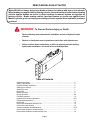
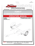
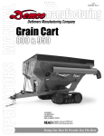
3-23-01
BH20001, Rev 5
Dethmers Manufacturing Company
DOING OUR BEST TO PROVIDE YOU THE BEST
DA20
ACTUATOR
OPERATORS MANUAL
READ complete manual CAREFULLY
BEFORE attempting operation.
ASSEMBLY
CALIBRATION
OPERATION
REPLACEMENT PARTS
DEMCO • Dethmers Mfg. Co. • 4010 320th St. • P.O. Box 189 • Boyden, IA 51234
PH: (712) 725-2311 or (712) 725-2302 • Toll Free: 1-800-543-3626 • FAX: 1-800-845-6420
www.demco-products.com
Page 1
NOTES
Page 2
DEMCO MODEL DA20 ACTUATOR
Model DA20 is a heavy duty surge brake actuator for trailers with two or four wheels.
When brakes are applied on the towing vehicle, forward inertia of trailer toward towing
vehicle applies brakes on trailer in direct relation to manner brakes are applied on
towing vehicle. Brake towing vehicle hard and brakes on trailer are applied hard.
Master cylinder push rod spring assembly protects system from hydraulic pressure
overload.
WARNING: To Prevent Serious Injury or Death
•
Review following instructions before installation and use of hydraulic brake
actuator.
•
Dealers or distributors must review these instructions with ultimate user.
•
Failure to follow these instructions, or failure to properly maintain braking
system after installation, can result in loss of braking action.
Table of Contents
General information ............................................................................................................ 3
Safety, Signal Words .......................................................................................................... 4
Equipment Safety Guidelines ............................................................................................. 5
Safety Sign Locations ......................................................................................................... 6
Safety Sign Care ................................................................................................................ 7
Remember ......................................................................................................................... 7
Before Operation ................................................................................................................ 8
During Operation .............................................................................................................. 8-9
Following Operation ........................................................................................................... 10
Highway and Transport Operations ................................................................................ 10-11
Performing Maintenance ................................................................................................... 11
Bolt Torque ........................................................................................................................ 12
DA20 Parts Breakdown and Parts List .............................................................................. 13
DA 20 Outer Case Options ................................................................................................ 14
Actuator Installation and Maintenance ............................................................................ 15-16
Demco Brake Products Limited Warranty .......................................................................... 17
Demco Brake Products Limited Warranty Cont. ................................................................ 18
Page 3
SAFETY
TAKE NOTE! THIS SAFETY ALERT SYMBOL FOUND THROUGHOUT THIS
MANUAL IS USED TO CALL YOUR ATTENTION TO INSTRUCTIONS INVOLVING
YOUR PERSONAL SAFETY AND SAFETY OF OTHERS. FAILURE TO FOLLOW
THESE INSTRUCTIONS CAN RESULT IN INJURY OR DEATH.
THIS SYMBOL MEANS
ATTENTION
BECOME ALERT
YOUR SAFETY IS INVOLVED!
SIGNAL WORDS
Note use following signal words DANGER,
WARNING, and CAUTION with safety messages.
Appropriate signal word for each has been selected
using following guidelines:
DANGER:
Indicates an imminently hazardous situation that,
if not avoided, will result in death or serious injury.
This signal word is to be limited to most extreme
situations typically for machine components which,
for functional purposes, cannot be guarded.
WARNING:
Indicates a potentially hazardous situation that, if
not avoided, could result in death or serious injury,
and includes hazards that are exposed when
guards are removed. It may also be used to alert
against unsafe practices.
CAUTION:
Indicates a potentially hazardous situation that, if
not avoided, may result in minor or moderate injury.
It may also be used to alert against unsafe
practices.
If you have questions not answered in this manual, require additional copies, or if your manual is damaged,
please contact your dealer or Dethmers Mfg. Co., P.O. Box 189, 4010 320th Street, Boyden, IA 51234
ph: (712) 725-2311 or (712) 725-2302 Toll Free: 1-800-543-3626 Fax: (712) 725-2380
http://www.demco-products.com
Page 4
SAFETY...YOU CAN LIVE WITH IT
EQUIPMENT SAFETY GUIDELINES
Every year many accidents occur which could have been avoided by a few seconds of
thought and a more careful approach to handling equipment. You the operator, can avoid
many accidents by observing and following precautions in this section. To avoid personal
injury, study the following precautions and insist those working with you, or you yourself,
follow them.
In order to provide a better view, certain illustrations in this manual may show an assembly
with a safety shield removed. However, equipment should never be operated in this condition.
Keep all shields in place. If shield removal becomes necessary for repairs, replace shield
prior to use.
Replace any caution, warning, danger or instruction safety decal that is not readable or is
missing. Location of such decals is indicated in this booklet.
Do not attempt to operate this equipment under the influence of alcohol or drugs.
Review safety instructions with all users.
Operator should be a responsible adult. DO NOT ALLOW PERSONS TO OPERATE OR
ASSEMBLE THIS UNIT UNTIL THEY HAVE DEVELOPED A THOROUGH UNDERSTANDING OF
SAFETY PRECAUTIONS AND HOW IT WORKS.
Do not paint over, remove, or deface any safety signs or warning decals on your equipment.
Observe all safety signs and practice instructions on them.
Never exceed limits of a piece of machinery. If its ability to do a job, or to do so safely is in
question-DON'T TRY IT.
Page 5
SAFETY SIGN LOCATIONS
Types of safety sign and locations on equipment are shown in illustration below. Good safety
requires that you familiarize yourself with various safety signs, type of warning, and area or
particular function related to that area, that requires your SAFETY AWARENESS.
This decal positioned as shown
BRAKES ON BRAKES OFF
DO NOT TOW TOWABLE
10/99
BH21003
Part # BH21003
Page 6
SAFETY SIGN CARE
• Keep safety signs clean and legible at all times.
• Replace safety signs that are missing or have become illegible.
• Replacement parts that displayed a safety sign should also display safety sign.
• Safety signs are available from your distributor, dealer parts department, or factory.
How to install safety signs:
• Be sure that installation area is clean and dry.
• Decide on exact position before you remove backing paper.
• Remove smallest portion of split backing paper.
• Align decal over specified area and carefully press small portion with exposed sticky
backing in place.
• Slowly peel back remaining paper and carefully smooth remaining portion of decal into
place.
• Small air pockets can be pierced with a pin and smoothed out using piece of decal
backing paper.
REMEMBER
Your best assurance against accidents is a careful and responsible operator. If there is any
portion of this manual or function you do not understand, contact your local authorized dealer
or manufacturer.
Page 7
BEFORE OPERATION:
• Carefully study and understand this manual.
• Always wear protective clothing and substantial shoes.
• Give equipment a visual inspection for any loose bolts, worn parts, or cracked welds, and
make necessary repairs. Follow maintenance safety instructions included in this manual.
• Be sure there are no tools lying on or in equipment.
• Do not use equipment until you are sure that area is clear, especially around children and
animals.
• Don't hurry learning process or take equipment for granted. Ease into it and become familiar
with your new equipment.
• Practice operation of your equipment and its attachments. Completely familiarize yourself
and other operators with its operation before using.
• Make sure that brakes are evenly adjusted.
• Make sure tow rating on vehicle is high enough for what it is towing.
• Do not allow anyone to stand between tongue or hitch and towing vehicle when
backing up to equipment.
• Securely attach to towing vehicle. Use appropriately sized hitch ball and/or hitch pin with a
mechanical retainer and attach safety chains.
• Criss cross chains under tongue and secure to draw bar cage, mounting loops,
or bumper frame.
DURING OPERATION
• SAFETY CHAINS If equipment is going to be transported on a public highway, safety
chains should be obtained and installed. Always follow state and local regulations
regarding safety chains and auxiliary lighting when towing equipment on a public highway.
Be sure to check with local law enforcement agencies for your own particular regulations.
Only safety chains (not an elastic or nylon/plastic tow straps) should be used to retain
connection between towing and towed equipment in event of separation of primary
attaching system.
• Install safety chains by criss crossing chains under tongue and secure to draw bar cage,
mounting loops, or bumper frame.
Page 8
• Beware of bystanders, PARTICULARLY CHILDREN! Always look around to make sure it is
safe to start engine of towing vehicle or move equipment. This is particularly important with higher
noise levels, as you may not hear people shouting.
• NO PASSENGERS ALLOWED- Do not carry passengers anywhere on or in equipment.
• Do not clean, lubricate, or adjust your equipment while it is moving.
• When halting operation, even periodically, set towing vehicles parking brake, shut off engine,
and remove the ignition key.
• Be extra careful when using on inclines.
• MANEUVER TOWING UNIT AT SAFE SPEEDS.
• Avoid loose gravel, rocks, and holes, they can be dangerous for equipment operation or movement.
• Allow for overall length when making turns.
• Keep all bystanders and pets clear of work area.
• Operate towing vehicle from operators seat only.
• Never leave running equipment attachments unattended.
• As a precaution, always recheck hardware on equipment following every 100 hours or 50 miles.
Correct all problems. Follow maintenance safety procedures.
Page 9
FOLLOWING OPERATION
• Following operation, or when unhitching, stop towing vehicle, set brakes,
shut off the engine and remove ignition key.
• Store unit in an area away from human activity.
• Do not permit children to play on or around stored unit.
• Make sure all parked units are on a hard, level surface and engage all safety devices.
• Wheel chocks may be needed to prevent unit from rolling.
HIGHWAY AND TRANSPORT OPERATIONS
• Adopt safe driving practices:
- Always drive at a safe speed relative to local conditions and ensure that your speed is low
enough for an emergency stop.
- Reduce speed prior to turns to avoid risk of overturning.
- Always keep towing vehicle in gear to provide engine braking when going downhill. Do not
coast.
- Do not drink and drive!
• Comply with state and local laws governing highway safety on public roads.
• Use approved accessory lighting, flags and necessary warning devices to protect operators of
other vehicles on highway during transport. Various safety lights and devices are available
from your dealer.
• Local laws should be checked for all highway lighting and marking requirements.
• Plan your route to avoid heavy traffic.
• Be a safe and courteous driver. Always yield to oncoming traffic in all situations, including narrow
bridges, intersections, etc.
• Be observant of bridge loading ratings. Do not cross bridges rated lower than the gross weight
at which you are operating.
Page 10
• Watch for obstructions overhead and side to side while transporting.
• Always operate equipment in a position to provide maximum visibility at all times. Make
allowances for increased length and weight of equipment when making turns and/or stopping.
PERFORMING MAINTENANCE
•
Good Maintenance is your responsibility. Poor maintenance is an invitation to trouble.
•
Make sure there is plenty of ventilation. Never operate engine of towing vehicle in
a closed building. Exhaust fumes may cause asphyxiation.
•
Before working on this unit, stop towing vehicle, set parking brakes, shut off engine
and remove ignition key.
•
Be certain all moving parts and attachments have come to a complete stop before
attempting to perform maintenance.
•
Always use safety supports and block wheels. Never use a jack to support unit.
•
Always use proper tools or equipment for job at hand.
•
Use extreme caution when making adjustments.
•
Follow torque chart in this manual when tightening bolts and nuts.
•
Openings in skin and minor cuts are susceptible to infection from brake fluid.
Without immediate medical treatment, serious infection and reactions can occur.
•
Replace all shields and guards after servicing and before moving.
•
After servicing, be sure all tools, parts and service equipment are removed.
•
Do not allow grease or oil to build up on the actuator.
•
When replacing bolts, refer to owners manual.
•
Refer to bolt torque chart for head identification marking.
•
Where replacement parts are necessary for periodic maintenance and servicing,
genuine factory replacement parts must be used to restore your equipment to original
specifications. Manufacturer will not claim responsibility for use of unapproved parts
or accessories and other damages as a result of their use.
•
If equipment has been altered in any way from original design, manufacturer does
not accept any liability for injury or warranty.
•
A fire extinguisher and first aid kit should be kept readily accessible while performing
maintenance on this equipment
Page 11
BOLT TORQUE
TORQUE DATA FOR STANDARD NUTS, BOLTS, AND CAPSCREWS.
Tighten all bolts to torques specified in chart unless otherwise noted. Check tightness of bolts
periodically, using bolt chart as guide. Replace hardware with same grade bolt.
NOTE: Unless otherwise specified, high-strength Grade 5 hex bolts are used throughout assembly
of equipment.
Bolt Torque for Standard bolts *
Torque Specifications
“A”
GRADE 2
lb-ft
(N.m)
GRADE 5
lb-ft
(N.m)
GRADE 8
lb-ft
(N.m)
1/4”
5/16”
3/8”
7/16”
1/2”
9/16”
5/8”
3/4”
7/8”
1”
6
10
20
30
45
70
95
165
170
225
9
18
30
50
75
115
150
290
420
630
12
25
45
80
115
165
225
400
650
970
(8)
(13)
(27)
(40)
(60)
(95)
(130)
(225)
(230)
(300)
(12)
(25)
(40)
(70)
(100)
(155)
(200)
(390)
(570)
(850)
(16)
(35)
(60)
(110)
(155)
(220)
(300)
(540)
(880)
(1310)
Bolt Torque for Metric bolts *
“A”
Torque figures indicated are valid for
non-greased or non-oiled threads and
heads unless otherwise specified.
Therefore, do not grease or oil bolts or
capscrews unless otherwise specified
in this manual. When using locking
elements, increase torque values
by 5%.
* GRADE or CLASS value for bolts
and capscrews are identified by their
head markings.
6
7
8
10
12
14
16
18
20
22
24
CLASS 8.8
lb-ft
(N.m)
CLASS 9.8
lb-ft
(N.m)
CLASS 10.9
lb-ft
(N.m)
9
15
23
45
78
125
194
268
378
516
654
10
18
25
50
88
140
216
-----
13
21
31
61
106
170
263
364
515
702
890
GRADE-2
CLASS 8.8
8.8
Page 12
(13)
(21)
(31)
(61)
(106)
(169)
(263)
(363)
(513)
(699)
(886)
GRADE-5
CLASS 9.8
9.8
(14)
(24)
(34)
(68)
(118)
(189)
(293)
-----
GRADE-8
CLASS 10.9
10.9
(17)
(29)
(42)
(83)
(144)
(230)
(357)
(493)
(689)
(952)
(1206)
13
12
23
24
11
Model DA20 ACTUATOR PARTS
19
21
10
5398 Master Cylinder Repair Kit
14
16
17
24
15
8
7
9
4
6
9
8
9
4
4
5
2
Model DA20 ACTUATOR PARTS LIST
5
1
4
4
34
27
27
26
25
26
RATED AT 20000#
REF.
NO. PART NO. QTY.
DESCRIPTION
1.
**03404
1 Inner Slider Tb. Chan. Down (channel down shown)
03757
1 Inner Slider Tube Channel Centered
09671
1 Inner Slider Tube Channel Up
2.
03522
1 Top Wear Pad
3
3.
03523
1 Bottom Wear Pad
4.
02206
12
1/4"-20UNC x 1/2" Flat Head Screw
** Specify Red Primed
5. SB12426
2 Damper Shock
(-97), Plated (-95) or
4
03409-95
1 Front Shock Pin
Yellow Chromate (-91) 6.
7.
**03412
1 Outer Case (see page 14 for other options)
finish.
8. 03411-95
2 Connecting Pin
9.
02363
6 5/32" x 1-1/4" Cotter Pin
10. 03410-95
1 Rear Shock Pin
11. *05693-95
1 Emergency Lever Spring
12.
05424
2 5/16" External Tooth Lock Washer
13.
05961
2 5/16"-18UNC x 5/8" Hex Head Bolt Gr. 5
14.
01076
4 1/4"-20UNC x 3/4" Hex Head Bolt Gr.5
35
15.
00057
4 1/4" Lock Washer
16.
*05951
1 Emergency Lever
17.
03534
1 Push Rod Assembly
18.
05680
1 Master Cylinder w/ gasket 05681
30
19.
05681
- Replacement Master Cyl. Gasket ONLY
20.
SB12098
1
1/8" pipe - 3/16" Inverted Flare Fitting w/orfice
30
21.
03876
1 Master Cylinder Cap w/ diaphragm and O-ring
30
22.
*05408
1 3/32" Cable with hooks (both ends)
36
SB10555
- Replacement S-hooks ONLY
28
23. 03866-95
1 Lever Guide
30
24.
05687
1 Master Cylinder Protective Boot
RATED AT 10000#
36
30
14
15
9
(gasket 05681 included)
Standard
Outer Case
Shown, See
Page 14 for
Other Options
20
18
22
30
29
31
RATED AT 12500#
27
36
26
30
32
RATED AT 20000#
33
26
RATED AT 20000#
#25.
26.
27.
#28.
#29.
30.
#31.
#32.
#33.
#34
#35
#36
-
DA20
09557
02434
02587
05593
05557
05823
04051
03756
07678
07203
07198
09747
03730
1
2
2
1
1
1
4
1
1
1
1
1
4
OPTIONS
Pintle Ring (10 ton capacity)
5/8"-11UNC x 4 1/2" Hex Head Bolt Gr.5
5/8"-11UNC Nylon Insert Lock Nut
Clevis (5 ton capacity)
2-5/16" Bulldog Coupler (12,500 lbs. capacity)
2" Bulldog Coupler (7000 lbs. capacity)
5/8"-11 UNC x 1-1/2" Hex Head Bolt Gr.5
Inner Slide Tube w/ Flat Plate
2-5/16" Lever Lock Coupler
20000# Forged Yoke (while supplies last)
2-5/16” coupler (welded on)
2-5/16” coupler drop tube (weld on)
5/8"-11UNC Stover Lock Nut (qty.w/#28,29,32)
5401
Lever Replacement Kit (incl. items w/*)
5398
Master Cylinder Repair Kit w/ gasket
Please order replacement parts by PART NO. and DESCRIPTION.
Bolts and Nuts not Included with optional receivers
# Not Included, these are optional. These are available in primed or plated. Please specify which finish when ordering
Page 13
OUTER CASE OPTIONS
03412
03548
03884
07105
07718
09486
09537
Page 14
WARNING
DEMCO MODEL DA20 BRAKE ACTUATOR
To Prevent Serious Injury Or Death:
•
Review all of the following instructions before installation and use of hydraulic brake
actuator.
•
Dealers or Distributors must review these instructions with ultimate user.
•
Failure to follow these instructions, or failure to properly maintain braking system after
installation, can result in loss of braking action which could cause severe property damage,
personal injury or death.
WARNING
To avoid personal injury or death, do not exceed lowest of (1) the rated
capacity of Model DA20 actuator, or (2) rated capacity of ball and hitch
being used, or (3) trailer's Gross Vehicle Weight Rating (GVWR).
Model DA20 brake actuator has a maximum load rating of 20,000 lbs.
GVWR and 2000 lbs. tongue load.
CAUTION
Do not weld on the outer case without disassembling actuator, damage
to inner slider tube will occur.
INSTALLATION
Model DA20 is completely assembled and ready to bolt into place.
1.
DA20 actuator comes with various mounting channels available.
2.
Connect and tighten all brake lines.
3.
Fill master cylinder (#18) with DOT 3 or 4 brake fluid.
4.
Bleed brake system using a pressure-type brake bleeder or manually, as follows:
a. Remove two 5/16" hex head bolts (#13) and lock washers (#12) that hold lever guide
(#23) and flat emergency lever spring (#11). Remove lever guide and emergency lever spring.
Using short strokes, pull forward on emergency lever (#16), pumping master cylinder until
brake fluid within master cylinder stops bubbling.
b. Attach a bleeder hose to bleeder valve on one of the wheels and submerge other end of hose
into a transparent container partially filled with brake fluid. Loosen bleeder valve one turn
and, watching hose in transparent container, use emergency lever to pump master cylinder
as long as air bubbles continue to leave the hose. When bubbles stop, close bleeder valve,
move to next wheel, and repeat process until all brakes have been bled. (Note: Check fluid level
in master cylinder frequently while bleeding brakes (every 4 or 5 strokes). Refill as necessary
to keep level above half full.)
Page 15
5. Once bleeding is completed, refill master cylinder and attach cap (#21) securely. Replace
emergency lever spring, lever guide, lock washers and 5/16" hex head bolts.
6. Test brakes by pulling emergency lever (#16) forward until it locks into its second notch
position. (Lever should be approximately straight up.) Attempt to rotate wheels in a forward
direction. If any wheels rotate, brakes must be adjusted. To adjust brakes, release
emergency lever from locked position, set each wheels brake adjustment up 2 or 3 notches
(per instructions in appropriate brake cluster manual). Repeat test procedure as necessary.
MAINTENANCE
1. Frequently check brake fluid level. (Fluid must be approved, clean and uncontaminated.)
2. Make sure actuator mounting bolts are secure.
3. Inspect actuator, replace bent, worn or damaged parts.
4. Be constantly aware of systems braking quality, make periodic checks as described in brakes owners
manual. Consult certified brake specialist to make necessary adjustments or repairs. Failure to do so
could result in loss of braking.
SERVICING THE EMERGENCY LEVER
If emergency lever (#16) of actuator is applied, it can be disengaged by using a screwdriver to lift
upward on front of flat emergency lever spring (#11) while pulling lever forward until released.
A thorough inspection of emergency lever, emergency lever spring, and cable with S-hooks is required.
Damaged parts must be replaced as follows:
a. Remove Cable S-hook (#22) from emergency lever (#16), emergency lever guide (#23) and flat
emergency lever spring (#11), then pull lever out of actuator outer case (#7) through cross-slot in top.
b. Install new emergency lever through cross-slot in top of outer case. Attach new emergency lever
spring and emergency lever guide.
c. Insert S-hook on emergency cable (#22) into hole in emergency lever (#16) and squeeze shut.
d. Add adequate brake fluid to master cylinder and bleed brake system per instructions 4-6
in installation section.
Page 16
DEMCO BRAKE PRODUCTS - LIMITED WARRANTY
1.
Extent and Duration of this Warranty:
Your Demco brake product is warranted to be free from defects in materials and workmanship under normal use
and service for a period of one year after date of purchase by original owner when properly installed, used and
maintained by purchaser.
When this Demco brake product is used as part of complete Demco braking system (actuators, brake lines, and
back plates), Demco warrants system to be free from defects in materials and workmanship for two years when
properly installed, used, and maintained by purchaser.
Any part of Demco brake system found to be defective in materials or workmanship will be repaired or replaced at
manufacturers option without charge for parts or labor to original owner.
2.
Manufacturer and Warrantor of Actuator:
Dethmers Manufacturing Co.
4010 320th Street
P.O. Box 189
Boyden, IA 51234
(712) 725-2311
3.
Repair or Replacement Procedure:
If your Demco brake product develops a defect during warranty period, promptly notify Dethmers Manufacturing
Co. customer service department. Until such notice is received, warrantor will not be responsible for any repair or
replacement.
Upon receipt of timely notice from you, warrantor will have a choice of options in replacing any part it determines
to be defective:
a) Warrantor may require you at your own expense to deliver or ship part to its factory or authorized
dealer. Any defective part will be repaired or replaced and returned to you or your authorized dealer
free of charge. Any part returned to warrantor and found not to be defective will be returned to you
freight collect with explanation.
b) Warrantor may ship a new part to dealer to be exchanged free of charge for defective
part returned by you.
c) Warrantor may ship or deliver a replacement part to you at your address.
4.
Limitations on Warranty Coverage:
Coverage under this warranty will be effective only when a copy of original invoice, showing date and location of
purchase, accompanies any claim for warranty.
Warrantor has no liability whatsoever and this warranty is null and void if any Demco brake product has been
misassembled or subjected to damage or neglect, negligence, misuse, accident or operated in any way contrary
to operating and maintenance instructions as specified in Demco owners manual for that product.
This warranty does not cover any product that has been altered or modified so as to affect the product’s
operation, performance or durability, or that has been modified to change intended use of product.
In addition, warranty does not extend to repairs made necessary by abnormal use, damage, unreasonable
use including failure to provide reasonable and necessary maintenance, or by use of parts, accessories or
other equipment which are incompatible with Demco brake products or affect its operation, performance
or durability.
Page 17
DEMCO BRAKE PRODUCTS - LIMITED WARRANTY CONTINUED
This warranty does not cover:
normal wear and tear.
road film or gravel damage to paint.
paint.
rust damage.
any Demco brake product that has been loaded in excess of load capacity stated on identification
label.
6) Accessory parts, materials or components.
1)
2)
3)
4)
5)
Warrantor has a policy of continuous product improvement. We reserve the right to change or
improve design of any Demco brake product, including but not limited to state of the art changes,
without assuming any obligation to modify any product previously manufactured.
Warrantor assumes no responsibility to owner for loss of use of product, loss of time, inconve
nience or other damage consequential or otherwise, including, but not limited to expense for
gasoline, expense of transporting product to dealer and expense of returning product, mechanics
travel time, telephone, telegram, fax, overnight delivery, or postage charges, road service/towing
charges, rental during time warranty repairs are being performed, travel, lodging, loss or damage
to personal property or loss of revenue or earnings.
5. Limitations of Implied Warranties:
All implied warranties, if any, expire and terminate upon expiration of this warranty. Some states
do not allow
limitation on how long an implied warranty lasts, so this limitation may not apply to you.
6. Limitation of Consequential Damages:
Warrantor’s responsibility under this warranty extends solely to repair or replacement of your
Demco brake product and its component parts. Warrantor does not assume responsibility for, nor
shall it be liable for, any special, incidental or consequential damages. Some states do not allow
exclusion or limitation of incidental or consequential damages, so above exclusion or limitation
may not apply to you.
7. Purchasers Rights:
This warranty gives you specific legal rights, and you may also have other rights which vary from
state to state.
8. Exclusive Warranty:
This is the only express warranty made by Dethmers Manufacturing Co. on your Demco product
and no agent, employee, or other person is allowed to change or add to this warranty.This war
ranty extends solely to repair or replacement of your Demco brake product and its component
parts. Warrantor does not assume any liability or responsibility not expressly covered by this
limited warranty.This warranty supersedes all prior warranties, written or implied.
DISCLAIMER
No other express warranty has been made or will be made on behalf of warrantor with respect to
Demco brake product or its instruction, operation, repair or replacement.Warrantor shall not be
responsible for damage, loss or damage to personal property, whether direct or indirect, and
whether arising in contract or tort.
Page 18
NOTES
Page 19
DETHMERS MFG. COMPANY
P.O. BOX 189
4010 320th St., BOYDEN, IA. 51234
PH: (712) 725-2311 or (712) 725-2302
FAX: (712) 725-2380
TOLL FREE: 1-800-54DEMCO (1-800-543-3626)
www.demco-products.com
Page 20