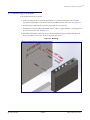
1
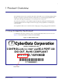
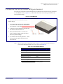
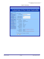
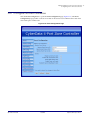
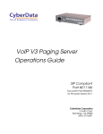
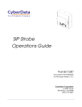
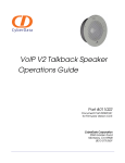
The IP Endpoint Company
VoIP V3 Zone Controller
4-Port Audio Out
Operations Guide
Part #011171
Document Part #930446E
for Firmware Version 6.0.2
CyberData Corporation
3 Justin Court
Monterey, CA 93940
(831) 373-2601
Operations Guide 930446E
SiP Compliant 011171
COPYRIGHT NOTICE:
© 2012, CyberData Corporation, ALL RIGHTS RESERVED.
This manual and related materials are the copyrighted property of CyberData Corporation. No part
of this manual or related materials may be reproduced or transmitted, in any form or by any means
(except for internal use by licensed customers), without prior express written permission of
CyberData Corporation. This manual, and the products, software, firmware, and/or hardware
described in this manual are the property of CyberData Corporation, provided under the terms of an
agreement between CyberData Corporation and recipient of this manual, and their use is subject to
that agreement and its terms.
DISCLAIMER: Except as expressly and specifically stated in a written agreement executed by
CyberData Corporation, CyberData Corporation makes no representation or warranty, express or
implied, including any warranty or merchantability or fitness for any purpose, with respect to this
manual or the products, software, firmware, and/or hardware described herein, and CyberData
Corporation assumes no liability for damages or claims resulting from any use of this manual or
such products, software, firmware, and/or hardware. CyberData Corporation reserves the right to
make changes, without notice, to this manual and to any such product, software, firmware, and/or
hardware.
OPEN SOURCE STATEMENT: Certain software components included in CyberData products are
subject to the GNU General Public License (GPL) and Lesser GNU General Public License (LGPL)
“open source” or “free software” licenses. Some of this Open Source Software may be owned by
third parties. Open Source Software is not subject to the terms and conditions of the CyberData
COPYRIGHT NOTICE or software licenses. Your right to copy, modify, and distribute any Open
Source Software is determined by the terms of the GPL, LGPL, or third party, according to who
licenses that software.
Software or firmware developed by Cyberdata that is unrelated to Open Source Software is
copyrighted by CyberData, subject to the terms of CyberData licenses, and may not be copied,
modified, reverse-engineered, or otherwise altered without explicit written permission from
CyberData Corporation.
TRADEMARK NOTICE: CyberData Corporation and the CyberData Corporation logos are
trademarks of CyberData Corporation. Other product names, trademarks, and service marks may be
the trademarks or registered trademarks of their respective owners.
Technical Support
The IP Endpoint Company
The fastest way to get technical support for your VoIP product is to
submit a VoIP Technical Support form at the following website:
http://www.cyberdata.net/support/contactsupportvoip.html
Phone: (831) 373-2601, Ext. 333
Email: [email protected]
Fax: (831) 373-4193
Company and product information is at www.cyberdata.net.
Operations Guide
930446E
CyberData Corporation
Revision History
Revision 930446E, which corresponds to firmware version 6.0.2, was released on October 16, 2012
and has the following changes:
• Updates Table 2-2, "Factory Default Settings".
Operations Guide
930446E
CyberData Corporation
i
Contents
Chapter 1 Product Overview
1
1.1 How to Identify this Product ................................................................................................................1
1.2 Product features .....................................................................................................................................2
1.3 Supported ................................................................................................................................................2
1.4 Product Specifications ...........................................................................................................................2
Chapter 2 Implementing the VoIP V3 Zone Controller
3
2.1 Parts List ..................................................................................................................................................3
2.2 Typical Installation .................................................................................................................................4
2.3 Setting up the VoIP Zone Controller ...................................................................................................5
2.3.1 Cables Used for Connecting to Legacy Analog Amplifiers ..................................................5
2.3.2 Connect to the Power Source ....................................................................................................5
Poe ................................................................................................................................................5
Non-Poe .......................................................................................................................................5
Chassis Ground ..........................................................................................................................5
2.3.3 Connect to the Network ............................................................................................................6
2.3.4 Confirm that the VoIP Zone Controller is Up and Running ................................................7
Confirm Power on, Network Connectivity, and Connection Speed ..................................7
2.3.5 Restore the Factory Default Settings as Required .................................................................8
2.4 Configuring the VoIP Zone Controller ...............................................................................................9
2.4.1 Gather the Required Configuration Information ..................................................................9
Static or DHCP Addressing? ...................................................................................................9
Username and Password for Configuration GUI .................................................................9
SIP Settings .................................................................................................................................9
2.4.2 VoIP Zone Controller Web Page Navigation .........................................................................10
2.4.3 Log in to the Configuration GUI ............................................................................................ 11
2.4.4 Configure the Device Parameters ...........................................................................................14
2.4.5 Configure the Network Parameters ...................................................................................... 16
2.4.6 Configure the SIP Parameters ................................................................................................. 18
Point-to-Point Configuration ................................................................................................. 21
2.4.7 Configure the Multicast Parameters ....................................................................................... 22
Assigning Priority .................................................................................................................... 23
2.4.8 Configure the Night Ringer Parameters ................................................................................ 24
2.4.9 Configure the Zone Parameters .............................................................................................. 26
Operating the VoIP Zone Controller ..................................................................................... 27
2.4.10 Configure the Audio Parameters .......................................................................................... 28
User-created Audio Files ......................................................................................................... 31
2.4.11 Configure the Event Parameters ...........................................................................................33
Example Packets for Events ....................................................................................................35
2.4.12 Configure the Autoprovisioning Parameters ...................................................................... 38
Autoprovisioning ..................................................................................................................... 40
2.5 Upgrading the Firmware ................................................................................................................... 43
Upgrade the Firmware ............................................................................................................ 44
Mounting the VoIP Zone Controller 45
A.1 Mount the VoIP Zone Controller .....................................................................................................45
A.1.1 Mounting Components ........................................................................................................... 45
A.1.2 Mounting Procedure ................................................................................................................ 46
Appendix A Setting Up a TFTP Server
Operations Guide
930446E
47
CyberData Corporation
ii
A.1 Set up a TFTP Server .......................................................................................................................... 47
A.1.1 In a LINUX Environment ........................................................................................................ 47
A.1.2 In a Windows Environment ................................................................................................... 47
Appendix B Troubleshooting/Technical Support
48
B.1 Frequently Asked Questions (FAQ) .................................................................................................. 48
B.1.1 Documentation .......................................................................................................................... 48
B.2 Contact Information ............................................................................................................................ 49
B.3 Warranty ............................................................................................................................................... 50
B.3.1 Warranty & RMA Returns within the United States ........................................................... 50
B.3.2 Warranty & RMA Returns Outside of the United States .................................................... 50
B.3.3 Spare in the Air Policy .............................................................................................................50
B.3.4 Return and Restocking Policy ................................................................................................. 51
B.3.5 Warranty and RMA Returns Page .......................................................................................... 51
Index
Operations Guide
52
930446E
CyberData Corporation
1
1 Product Overview
The CyberData VoIP V3 Zone Controller with Audio-Out enables access to existing paging speakers
through a VoIP phone system. The interface is designed to use a standard paging amplifier with
audio inputs and supports paging up to 15 zone groups from a VoIP phone.
The VoIP Zone Controller is a PoE-enabled, single SIP-endpoint, enabling user-defined paging
zones through RCA line level output connections to legacy analog amplifiers to existing legacy
analog speakers.
SIP compliant IP-PBX's can now interface with existing legacy analog paging speaker installations.
1.1 How to Identify this Product
To identify the VoIP Zone Controller, look for a model number label similar to the one shown in
Figure 1-1. The model number on the label should be 011171.
Figure 1-1. Model Number Label
WWW.CYBERDATA.NET
CONTROLLER,V3 VoIP ZONE,4-PORT AUDIO OUT, RoHS COMPLIANT
011171B / 021065B
171000001
Model number
Operations Guide
930446E
CyberData Corporation
Product Overview 2
Product features
1.2 Product features
• Delayed paging
• Night Ringer
• Compatible with more IP/PBX servers
• SIP RFC 3261 compatible
• PoE 802.3af enabled (Power-over-ethernet)
• Dual-speed ethernet 10/100 Mbps
• 4 Paging zones
• 15 Paging zone groups
• Page all
• Web-based configuration
• Web-based firmware upgradeable
• Connector for external power supply
• Small footprint
1.3 Supported
• HTTP Web-based configuration
• Provides an intuitive GUI for easy system configuration and verification of speaker operations.
• DHCP Client
• TFTP Client
• Audio Codec
• G.711 U-law
• DTMF detection
1.4 Product Specifications
Specifications
Operations Guide
Regulatory Compliance
FCC Class A, UL 60950, CE
Power Requirement
PoE or 48V DC
Connection Speed
10/100 Mbps
Protocol
SIP compliant
Part Number
011171
Dimensions
6.11”L x 4.05”W x 1.15” H
Weight
1.2 pounds
930446E
CyberData Corporation
3
2 Implementing the VoIP V3 Zone Controller
The topics in this chapter provide information on setting up, configuring, and using the VoIP Zone
Controller.
2.1 Parts List
The packaging for the VoIP Zone Controller includes the parts in this illustration.
Table 2-1. Parts List
Quanti
ty
Operations Guide
Part Name
1
VoIP V3 Zone Controller
1
Installation Quick Reference Guide
1
Mounting Kit
930446E
Illustration
CyberData Corporation
Implementing the VoIP V3 Zone Controller 4
Typical Installation
2.2 Typical Installation
Figure 2-1 illustrates how the VoIP Zone Controller is normally installed as part of a paging system.
Figure 2-1. Typical Installation
VoIP V3 Zone Controller 4-Port Audio Out
Generic PoE Switch
1
2
3
4
5
6
IP Phone
IP PBX Server
Analog Amplifiers Paging Speakers
Operations Guide
930446E
CyberData Corporation
Implementing the VoIP V3 Zone Controller 5
Setting up the VoIP Zone Controller
2.3 Setting up the VoIP Zone Controller
Before you set up the VoIP Zone Controller, be sure that you have received all the parts described in
Section 2.1, "Parts List".
2.3.1 Cables Used for Connecting to Legacy Analog Amplifiers
The VoIP Zone Controller connects to zones through RCA line level output connections to legacy
analog amplifiers to existing legacy analog speakers.
2.3.2 Connect to the Power Source
Figure 2-2. Connecting to the Power Source
PoE
To set up the VoIP Zone Controller, connect the
device to your network:
Poe
• For PoE, plug one end of an 802.3af Ethernet
cable into the VoIP Zone Controller Ethernet
port. Plug the other end of the Ethernet cable
into your network. See the figure on the left.
Non PoE (with 48 VDC power supply)
Non-Poe
• For Non-PoE, connect the VoIP Zone
Controller to a 48VDC power supply. See the
figure on the left.
Chassis Ground
Chassis Ground
• If required, connect the earth grounding wire
to the Chassis Ground on the back of the unit.
See the figure on the left.
Chassis Ground
Operations Guide
930446E
CyberData Corporation
Implementing the VoIP V3 Zone Controller 6
Setting up the VoIP Zone Controller
2.3.3 Connect to the Network
Plug one end of a standard Ethernet cable into the VoIP Zone Controller Ethernet port. Plug the
other end into your network.
Figure 2-3. Connecting to the Network
Operations Guide
930446E
CyberData Corporation
Implementing the VoIP V3 Zone Controller 7
Setting up the VoIP Zone Controller
2.3.4 Confirm that the VoIP Zone Controller is Up and Running
The indicator LEDs on the front of the VoIP Zone Controller verify the unit’s operations.
Figure 2-4. VoIP Zone Controller Indicator LEDs
Front View with LEDs
Link
(YELLOW LED)
Activity
(GREEN LED)
Status
(GREEN LED)
Audio Activity
(GREEN LED)
Power Status
(BLUE LED)
2.3.4.1 Confirm Power on, Network Connectivity, and Connection Speed
When you plug in the Ethernet cable or power supply:
• The round, BLUE Power Status LED on the front of the VoIP Zone Controller comes on
indicating that the power is on.
• The square, YELLOW Link LED above the Ethernet port indicates that the network connection
has been established. The Link LED changes color to confirm the auto-negotiated connection
speed:
• This LED is YELLOW at 10 Mbps.
• This LED is ORANGE at 100 Mbps.
• The square, GREEN Activity LED above the Ethernet port blinks when there is network
activity.
• The round, GREEN Status LED comes on after the device is booted and initialized. This LED
blinks when the unit is operational.
• The square, GREEN Audio Activity LEDs turn on solid when a Zone is being paged.
Operations Guide
930446E
CyberData Corporation
Implementing the VoIP V3 Zone Controller 8
Setting up the VoIP Zone Controller
2.3.5 Restore the Factory Default Settings as Required
The VoIP Zone Controller is delivered with factory set default values for the following parameters.
Use the RTFM switch (see Figure 2-5) on the back of the unit to restore these parameters to the
factory default settings.
Figure 2-5. RTFM Switch
Back View with RTFM Switch
To restore the VoIP Zone Controller’s factory
default settings:
1. Use a paper clip to press and hold the RTFM
switch while all of the indicator LEDs turn off.
See the picture on the right.
2. Continue to press the RTFM switch until after
the indicator LEDs turn back on.
3. Release the RTFM switch. All of the VoIP
Zone Controller settings will be restored to
the factory default settings.
Paper clip
RTFM switch
4. You will hear the "Restoring defaults..." audio
message play through all ports before the
device reboots.
Note
When you perform the RTFM procedure in Figure 2-5, the factory default settings are
restored. The default parameters for access are shown in Table 2-2.
Table 2-2. Factory Default Settings
Parameter
Factory Default Setting
IP Addressing
DHCP
IP Addressa
10.10.10.10
Web Access Username
admin
Web Access Password
admin
Subnet Maska
255.0.0.0
Default Gatewaya
10.0.0.1
a. Default if there is not a DHCP server present.
Operations Guide
930446E
CyberData Corporation
Implementing the VoIP V3 Zone Controller 9
Configuring the VoIP Zone Controller
2.4 Configuring the VoIP Zone Controller
Use this section to configure the VoIP Zone Controller.
2.4.1 Gather the Required Configuration Information
Have the following information available before you configure the VoIP Zone Controller.
2.4.1.1 Static or DHCP Addressing?
Know whether your system uses static or dynamic (DHCP) IP addressing. If it uses static
addressing, you also need to know the values to assign to the following VoIP Zone Controller
parameters:
• IP Address
• Subnet Mask
• Default Gateway
2.4.1.2 Username and Password for Configuration GUI
Determine the Username and Password that will replace the defaults after you initially log in to the
configuration GUI.
• The Username is case-sensitive, and must be from four to 25 alphanumeric characters long.
• The Password is case-sensitive, and must be from four to 20 alphanumeric characters long.
2.4.1.3 SIP Settings
To configure the SIP parameters, determine whether you want to register the VoIP Zone Controller.
If you do, determine the number of minutes the registration lease remains valid, and whether you
want to automatically unregister when you reboot. To configure the SIP parameters, you also need
to determine the values for these parameters:
• SIP Server IP Address
• Remote and Local SIP Port Numbers
• SIP User ID, and Authenticate ID and Password for this User ID
Operations Guide
930446E
CyberData Corporation
Implementing the VoIP V3 Zone Controller 10
Configuring the VoIP Zone Controller
2.4.2 VoIP Zone Controller Web Page Navigation
Table 2-3 shows the navigation buttons that you will see on every VoIP Zone Controller web page.
Table 2-3. V3 Paging Amplifier Web Page Navigation
Web Page Item
Description
Link to the Home page.
Link to the Device Configuration page.
Link to the Networking page.
Link to go to the SIP Configuration page.
Link to the Multicast Configuration page.
Link to go to the Nightringer page.
Link to go to the Zone Configuration page.
Link to the Audio Configuration page.
Link to the Event Configuration page.
Link to the Autoprovisioning Configuration page.
Link to the Update Firmware page.
Operations Guide
930446E
CyberData Corporation
Implementing the VoIP V3 Zone Controller 11
Configuring the VoIP Zone Controller
2.4.3 Log in to the Configuration GUI
1. Open your browser to the VoIP Zone Controller IP address.
Note
If the network does not have access to a DHCP server, the device will default to an IP
address of 10.10.10.10.
Note
Make sure that the PC is on the same IP network as the VoIP Zone Controller.
Note
You may also download CyberData’s VoIP Discovery Utility program which allows you to
easily find and configure the default web address of the CyberData VoIP products.
CyberData’s VoIP Discovery Utility program is available at the following website address:
http://www.cyberdata.net/support/voip/discovery_utility.html
The unit ships in DHCP mode. To get to the Home page, use the discovery utility to scan for
the device on the network and open your browser from there.
Note
To work with the VoIP Zone Controller configuration after the initial configuration, log in
using the IP address you assign to the device. Section 2.4.5, "Configure the Network
Parameters" provides instructions for entering the IP address.
2. When prompted, use the following default Username and Password to open the configuration
Home page:
Username: admin
Password: admin
Change the
To change the default Web access Username and Password:
Default Username
1. Enter the new Username from four to 25 alphanumeric characters in the Change Username
and Password
field. The Username is case-sensitive.
2. Enter the new Password from four to 20 alphanumeric characters in the Change Password field.
The Password is case-sensitive.
3. Enter the new password again in the Re-enter New Password field.
Click Save Settings.
Operations Guide
930446E
CyberData Corporation
Implementing the VoIP V3 Zone Controller 12
Configuring the VoIP Zone Controller
Figure 2-6. Home Page
Operations Guide
930446E
CyberData Corporation
Implementing the VoIP V3 Zone Controller 13
Configuring the VoIP Zone Controller
4. On the Home Page, review the setup details and navigation buttons described in Table 2-4.
Table 2-4. Home Page Overview
Web Page Item
Description
Device Settings
Device Name
Shows the device name (25 character limit).
Change Username
Type in this field to change the username (25 character limit).
Change Password
Type in this field to change the password (19 character limit).
Re-enter Password
Type the password again in this field to confirm the new password
(19 character limit).
Current Settings
Serial Number
Shows the device serial number.
Mac Address
Shows the device Mac address.
Firmware Version
Shows the current firmware version.
IP Addressing
Shows the current IP addressing setting (DHCP or Static).
IP Address
Shows the current IP address.
Subnet Mask
Shows the current subnet mask address.
Default Gateway
Shows the current default gateway address.
DNS Server 1
Shows the current DNS Server 1 address.
DNS Server 2
Shows the current DNS Server 2 address.
SIP Mode is
Shows the current status of the SIP Mode.
Event Reporting is
Shows the current status of the Event Reporting.
Nightring is
Shows the current status of the Nightringer.
Click the Save button to save your configuration settings.
Note: You need to reboot for changes to take effect.
Click on the Reboot button to reboot the system.
At this point you can:
• Review the VoIP Zone Controller’s Current Settings. Use the RTFM switch to restore the factory
default settings. See Section 2.3.5, "Restore the Factory Default Settings as Required".
• Configure the network parameters. Click the Networking button and refer to Section 2.4.5,
"Configure the Network Parameters" for instructions.
• Configure the SIP parameters. Click SIP Config and see Section 2.4.6, "Configure the SIP
Parameters".
• Configure the Zone parameters. Click Zone Config and see Section 2.4.9, "Configure the Zone
Parameters" for instructions.
Note
Operations Guide
Click the Upgrade Firmware button any time you need to upload new versions of the
firmware. Refer to Section 2.5, "Upgrading the Firmware" for instructions.
930446E
CyberData Corporation
Implementing the VoIP V3 Zone Controller 14
Configuring the VoIP Zone Controller
2.4.4 Configure the Device Parameters
1. Click the Device Configuration button to open the Device Configuration page. See Figure 2-7.
Figure 2-7. Device Configuration Page
Operations Guide
930446E
CyberData Corporation
Implementing the VoIP V3 Zone Controller 15
Configuring the VoIP Zone Controller
2. On the Device Configuration page, you may enter values for the parameters indicated in
Table 2-5.
Table 2-5. Device Configuration Parameters
Web Page Item
Description
Miscellaneous Settings
Beep on Initialization
When selected, you will hear a beep when the speaker initializes.
Beep on Page
When selected, you will hear a beep when a page is sent from the
device.
Test Audio
Port 1 through Port 4
Select the desired port(s) for the audio test.
Click on the Test Audio button to do an audio test. When the Test
Audio button is pressed, you will hear a voice message for testing the
device audio quality and volume.
Click the Save button to save your configuration settings.
Note: You need to reboot for changes to take effect.
Click on the Reboot button to reboot the system.
3. After changing the parameters, click the Save button.
Operations Guide
930446E
CyberData Corporation
Implementing the VoIP V3 Zone Controller 16
Configuring the VoIP Zone Controller
2.4.5 Configure the Network Parameters
Configuring the network parameters enables your network to recognize the VoIP Zone Controller
and communicate with it. Click Network Setup on the Home page to open the Network
Configuration page.
Figure 2-8. Network Setup Page
Operations Guide
930446E
CyberData Corporation
Implementing the VoIP V3 Zone Controller 17
Configuring the VoIP Zone Controller
On the Network Setup page, enter values for the parameters indicated in Table 2-6.
Table 2-6. Network Configuration Parameters
Web Page Item
Description
Stored Network Settings
Shows the settings stored in non-volatile memory.
IP Addressing
Select either DHCP IP Addressing or Static IP Addressing by
marking the appropriate radio button. If you select Static, configure
the remaining parameters indicated in Table 2-6. If you select DHCP,
go to Step 3.
IP Address
Enter the Static IP address.
Subnet Mask
Enter the Subnet Mask address.
Default Gateway
Enter the Default Gateway address.
DNS Server 1
Enter the DNS Server 1 address.
DNS Server 2
Enter the DNS Server 2 address.
Current Network Settings
Shows the current network settings.
IP Address
Shows the current Static IP address.
Subnet Mask
Shows the current Subnet Mask address.
Default Gateway
Shows the current Default Gateway address.
DNS Server 1
Shows the current DNS Server 1 address.
DNS Server 2
Shows the current DNS Server 2 address.
Click the Save button to save your configuration settings.
Note: You need to reboot for changes to take effect.
Click on the Reboot button to reboot the system.
On this page:
1. Specify whether you use Static or DHCP IP Addressing by marking the appropriate radio
button. Then, if you select Static, go to Step 2.
2. For Static IP Addressing, also enter values for the following parameters:
• The VoIP Zone Controller’s IP Address: The VoIP Zone Controller is delivered with a factory
default IP address. Change the default address to the correct IP address for your system.
• The Subnet Mask.
• The Default Gateway.
3. Click Save when you are finished.
4. Click Reboot for the new settings to take effect.
Operations Guide
930446E
CyberData Corporation
Implementing the VoIP V3 Zone Controller 18
Configuring the VoIP Zone Controller
2.4.6 Configure the SIP Parameters
The SIP parameters enable the VoIP Zone Controller to contact and register with the SIP server. On
the Home page, click SIP Config to open the SIP Configuration page.
Figure 2-9. SIP Configuration Page
Operations Guide
930446E
CyberData Corporation
Implementing the VoIP V3 Zone Controller 19
Configuring the VoIP Zone Controller
5. On the SIP Setup page, enter values for the parameters indicated in Table 2-7.
Table 2-7. SIP Configuration Parameters
Web Page Item
Description
SIP Settings
SIP Server
Type the SIP server represented as either a numeric IP address
in dotted decimal notation or the fully qualified host name (255
character limit [FQDN]).
Remote SIP Port
Type the Remote SIP Port number (default 5060)
(8 character limit).
Local SIP Port
Type the Local SIP Port number (default 5060)
(8 character limit).
Outbound Proxy
Type the Outbound Proxy as either a numeric IP address in
dotted decimal notation or the fully qualified host name
(255 character limit [FQDN]).
Outbound Proxy Port
Type the Outbound Proxy Port number (8 character limit).
SIP User ID
Type the SIP User ID (up to 64 alphanumeric characters).
Authenticate ID
Type the Authenticate ID
(up to 64 alphanumeric characters).
Authenticate Password
Type the Authenticate Password (up to 64 alphanumeric
characters).
Register with a SIP Server
Enable or disable SIP Registration.
For information about Point-to-Point Configuration, see Section
2.4.6.1, "Point-to-Point Configuration".
Re-registration Interval (in seconds)
Type the SIP Registration lease time in seconds (default is 60
minutes) (8 character limit). Re-registration Interval (in seconds)
Unregister on Reboot
When selected, on boot, the device will first register with a SIP
server with a expiration delay of 0 seconds. This has the effect
of unregistering any current devices on this extension.
Buffer SIP Calls
When this is enabled, SIP calls to the device will be stored in
memory and will play when either the call is terminated or the
buffer is full. The receive buffer is 2MB in size and this is equal
to about four minutes of ulaw encoded audio.
Click the Save button to save your configuration settings.
Note: You need to reboot for changes to take effect.
Click on the Reboot button to reboot the system.
1. Enter the IP address of the SIP Server.
2. Enter the port numbers used for SIP signaling:
a. Remote SIP Port
b. Local SIP Port
Operations Guide
930446E
CyberData Corporation
Implementing the VoIP V3 Zone Controller 20
Configuring the VoIP Zone Controller
3. Enter the SIP registration parameters:
a. SIP User ID
b. Authenticate ID
c. Authenticate Password
4. For SIP Registration, designate whether you want the device to register with your SIP server.
5. At Unregister on Reboot:
a. Select Yes to automatically unregister the VoIP Zone Controller when you reboot it.
b. Select No to keep the VoIP Zone Controller registered when you reboot it.
6. In the Register Expiration field, enter the number of seconds the VoIP Zone Controller
registration lease remains valid with the SIP Server. The VoIP Zone Controller automatically reregisters with the SIP server before the lease expiration timeout.
7. Click Save.
8. Click Reboot for the new settings to take effect.
Operations Guide
930446E
CyberData Corporation
Implementing the VoIP V3 Zone Controller 21
Configuring the VoIP Zone Controller
2.4.6.1 Point-to-Point Configuration
When the board is set to not register with a SIP server, it's possible to set the device to dial out to a
single endpoint. To do this, do the following:
1. On the SIP Configuration page (Figure 2-10), make sure that the Register with a SIP Server
parameter is not selected.
2. Type the IP address of the remote device that you want to contact into the Dial out Extension
field
Note
The delayed DTMF functionality is available in the Point-to-Point Mode.
Note
Establishing point-to-point SiP calls may not work with all phones.
Figure 2-10. SIP Configuration Page Set to Point-to-Point Mode
Device is set to NOT register with a SIP server
Operations Guide
930446E
CyberData Corporation
Implementing the VoIP V3 Zone Controller 22
Configuring the VoIP Zone Controller
2.4.7 Configure the Multicast Parameters
The Multicast Configuration page allows the Zone Controller to join up to one paging zone for
receiving an emergency ulaw/alaw encoded RTP audio stream. A paging zone can consist of one or
many CyberData multicast group-enabled products. There is no limit to how many devices can be in
a given paging zone. A multicast group is defined by a multicast address and port number. Each
multicast group is assigned a priority, allowing simultaneously arriving pages to be serviced based
on importance. Multicast groups are compatible with IGMP through version three. The Zone
Controller will preempt all other audio when receiving a multicast page because it is considered
emergency priority.
1. Click on the Multicast Configuration button to open the Multicast Configuration page. See
Figure 2-11.
Figure 2-11. Multicast Configuration Page
Operations Guide
930446E
CyberData Corporation
Implementing the VoIP V3 Zone Controller 23
Configuring the VoIP Zone Controller
2. On the Multicast Configuration page, enter values for the parameters indicated in Table 2-8.
Table 2-8. Multicast Configuration Parameters
Web Page Item
Description
Enable Multicast Operation
Enables or disables multicast operation.
Device Settings
Priority
Emergency
The priority is fixed as "Emergency" and it is the only group
that is available on this device.
Address
Enter the multicast IP Address for this multicast group (15
character limit).
Port (range can be from 2000 to 65535)
Enter the port number for this multicast group (5 character
limit).
Note: The multicast ports have to be even values. The
webpage will enforce this restriction.
Multicast Group Name
Assign a descriptive name for this multicast group (25
character limit).
Click the Save button to save your configuration settings.
Note: You need to reboot for changes to take effect.
Click on the Reboot button to reboot the system.
3. After changing the parameters, click on the Save button.
2.4.7.1 Assigning Priority
When playing a multicast stream, all other audio will be preempted as the multicast group is
considered an emergency group.
Note
Ringtones and
Nightringtones
Operations Guide
SIP calls, multicast streams, ring tones, ringback tones, and nightring tones are all
prioritized.
Ringtones all play at the same priority level. This means that it is possible to have a nightring tone
and a normal ringtone playing at the same time.
930446E
CyberData Corporation
Implementing the VoIP V3 Zone Controller 24
Configuring the VoIP Zone Controller
2.4.8 Configure the Night Ringer Parameters
Caution
Nightringer requires SIP Registration. Nightringer cannot be used in peer to peer mode.
GENERAL ALERT
1. Click on the Nightringer button to open the Nightringer Configuration page. See Figure 2-12.
Figure 2-12. Nightringer Configuration Setup
Operations Guide
930446E
CyberData Corporation
Implementing the VoIP V3 Zone Controller 25
Configuring the VoIP Zone Controller
2. On the Nightringer Configuration page, enter values for the parameters indicated
in Table 2-9.
Table 2-9. Nightringer Configuration Parameters
Web Page Item
Description
Enable Nightringer
When the nightringer is enabled, the unit will attempt to register a
second extension with the SIP server. Any calls made to this
extension will play a ringtone.
Nightringer Settings
SIP Server
Type the SIP server represented as either a numeric IP address in
dotted decimal notation.
Remote SIP Port
Type the Remote SIP Port number (default 5060)
(8 character limit).
Local SIP Port
Type the Local SIP Port number (default 5061)
(8 character limit).
Note: This value cannot be the same as the Local SIP Port found
on the SIP Configuration Page.
User ID
Type the User ID (up to 64 alphanumeric characters).
Authenticate ID
Type the Authenticate ID (up to 64 alphanumeric characters).
Authenticate Password
Type the Authenticate Password (up to 64 alphanumeric
characters).
Re-registration Interval (in seconds)
Type the SIP Registration lease time in seconds (default is 60
minutes) (8 character limit). Re-registration Interval (in seconds)
Play audio on ports
When selected, a user-defined audio file is sent to the specified
port(s) when the night ringer is activated.
Click the Save button to save your configuration settings.
Note: You need to reboot for changes to take effect.
Click on the Reboot button to reboot the system.
3. After changing the parameters, click on the Save button.
4. Click Reboot for the new settings to take effect.
Operations Guide
930446E
CyberData Corporation
Implementing the VoIP V3 Zone Controller 26
Configuring the VoIP Zone Controller
2.4.9 Configure the Zone Parameters
• Each audio output jack on the VoIP Zone Controller represents a Zone.
• A Group is comprised of a combination of one or more Zones.
• You will need to plug any Zones that are used on the VoIP Zone Controller into an analog
amplifier. Any speakers attached to the amplifier will be present in the Zone.
1. Click on the Zone Config button to open the Zone Configuration page. See Figure 2-13.
Figure 2-13. Zone Configuration Setup
Operations Guide
930446E
CyberData Corporation
Implementing the VoIP V3 Zone Controller 27
Configuring the VoIP Zone Controller
2. On the Zone Configuration page, enter values for the parameters indicated
in Table 2-10.
Table 2-10. Zone Configuration Parameters
Web Page Item
Description
Zones
Bypass DTMF
When selected, the ports in Zone 00 will be paged without
waiting for DTMF entry.
Port 1 through Port 4 Checkboxes
Check the box for the port(s) that comprise the zone.
Click the Save button to save your configuration settings.
Note: You need to reboot for changes to take effect.
Click on the Reboot button to reboot the system.
3. After changing the parameters, click on the Save button.
4. Click Reboot for the new settings to take effect.
2.4.9.1 Operating the VoIP Zone Controller
To operate the VoIP Zone Controller:
1. Call to make a page. The VoIP Zone Controller will generate a tone over the phone.
2. When you hear this tone, enter the two-digit code for the group that you want to page.
Note
If the Bypass DTMF setting is enabled, go to Step 4.
3. If the zone is valid, the VoIP Zone Controller will play the user-defined "good zone" sound. Go
to Step 4.
Note
If the zone is invalid, the VoIP Zone Controller will play the user-defined "bad zone"
sound. Repeat Step 2.
4. When you hear the "good zone" tone, you can begin speaking.
Operations Guide
930446E
CyberData Corporation
Implementing the VoIP V3 Zone Controller 28
Configuring the VoIP Zone Controller
2.4.10 Configure the Audio Parameters
Click the Audio Config button to open the Audio Configuration page. See Figure 2-14. The Audio
Configuration page is used to add custom audio to the board. User uploaded audio will take
precedence over the audio files shipped with the VoIP Zone Controller.
Figure 2-14. Audio Configuration Page
Operations Guide
930446E
CyberData Corporation
Implementing the VoIP V3 Zone Controller 29
Configuring the VoIP Zone Controller
Figure 2-15. Audio Configuration Page
Note
Operations Guide
To test an audio file, first select the ports (located at the bottom of the Audio Configuration
Page) that you want to play the audio file to, and then press the Play button for the desired
audio file.
930446E
CyberData Corporation
Implementing the VoIP V3 Zone Controller 30
Configuring the VoIP Zone Controller
On the Audio Configuration page, enter values for the parameters indicated in Table 2-11.
Note
Each entry on the Audio Configuration page replaces one of the stock audio files on the
board. When the input box displays the word default, the VoIP Zone Controller is using the
stock audio file. If that file is replaced with a user file, it will display the uploaded filename.
Table 2-11. Audio Configuration Parameters
Web Page Item
Description
Audio Files
0-9
The name of the audio configuration option is the same as the spoken
audio that plays on the board (24 character limit).
'0' corresponds to the spoken word “zero.”
'1' corresponds to the spoken word “one.”
'2' corresponds to the spoken word “two.”
'3' corresponds to the spoken word “three.”
'4' corresponds to the spoken word “four.”
'5' corresponds to the spoken word “five.”
'6' corresponds to the spoken word “six.”
'7' corresponds to the spoken word “seven.”
'8' corresponds to the spoken word “eight.”
'9' corresponds to the spoken word “nine.”
Dot
Corresponds to the spoken word “dot.” (24 character limit).
Audiotest
Corresponds to the message “This is the CyberData IP speaker test
message...” (24 character limit).
Pagetone
Corresponds to a simple tone that is unused by default (24 character limit).
Invalid Zone
Corresponds to the message “Invalid Zone” (24 character limit).
Your IP Address is
Corresponds to the message “Your IP address is...” (24 character limit).
Rebooting
Corresponds to the spoken word “Rebooting” (24 character limit).
Restoring default
Corresponds to the message “Restoring default” (24 character limit).
Night Ring
Specifies the ringtone for nightring. By default this parameter uses the
same audio file that is selected for the Ring Tone parameter.
Ports to play test audio
Port 1 through Port 4
Select the desired port(s) for the audio test.
The Browse button will allow you to navigate to and select an audio file.
The Play button will play that audio file.
The Delete button will delete any user uploaded audio and restore the
stock audio file.
The Save button will download a new user audio file to the board once
you've selected the file by using the Browse button. The Save button will
delete any pre-existing user-uploaded audio files.
Operations Guide
930446E
CyberData Corporation
Implementing the VoIP V3 Zone Controller 31
Configuring the VoIP Zone Controller
2.4.10.1 User-created Audio Files
User created audio files should be saved in the following format:
RIFF (little-endian) data, WAVE audio, Microsoft PCM, 16 bit, mono 8000 Hz
You can use the free utility Audacity to convert audio files into this format. See Figure 2-16 through
Figure 2-18.
Figure 2-16. Audacity 1
Figure 2-17. Audacity 2
Operations Guide
930446E
CyberData Corporation
Implementing the VoIP V3 Zone Controller 32
Configuring the VoIP Zone Controller
When you export an audio file with Audacity, save the output as:
• WAV (Microsoft) signed 16 bit PCM.
Figure 2-18. WAV (Microsoft) signed 16 bit PCM
WAV (Microsoft) signed 16 bit PCM
Operations Guide
930446E
CyberData Corporation
Implementing the VoIP V3 Zone Controller 33
Configuring the VoIP Zone Controller
2.4.11 Configure the Event Parameters
Click the Event Config button to open the Event Configuration page (Figure 2-19). The Event
Configuration page specifies a remote server that can be used to receive HTTP POST events when
actions take place on the board.
Figure 2-19. Event Configuration Page
Operations Guide
930446E
CyberData Corporation
Implementing the VoIP V3 Zone Controller 34
Configuring the VoIP Zone Controller
Table 2-12 shows the web page items on the Event Configuration page.
Table 2-12. Event Configuration
Web Page Item
Description
Enable Event Generation
When selected, Event Generation is enabled.
Remote Event Server
Remote Event Server IP
Type the Remote Event Server IP address.
(64 character limit)
Remote Event Server Port
Type the Remote Event Server port number.
(8 character limit)
Remote Event Server URL
Type the Remote Event Server URL.
(127 character limit)
Events
Enable Call Active Events
When selected, Call Active Events are enabled.
Enable Call Terminated Events
When selected, Call Terminated Events are enabled.
Enable Night Ring Events
When selected, there is a notification when the unit
receives a night ring.
Enable Power On Events
When selected, Power On Events are enabled.
Enable 60 Second Heartbeat Events
When selected, 60 Second Heartbeat Events are
enabled.
Click the Save button to save your configuration settings.
Note: You need to reboot for changes to take effect.
Click on the Test Event button to test an event.
Click on the Reboot button to reboot the system.
Operations Guide
930446E
CyberData Corporation
Implementing the VoIP V3 Zone Controller 35
Configuring the VoIP Zone Controller
2.4.11.1 Example Packets for Events
The server and port are used to point to the listening server and the 'Remote Event Server URL' is
the destination URL (typically the script running on the remote server that's used to parse and
process the POST events).
Note
The XML is URL-encoded before transmission so the following examples are not completely
accurate.
Here are example packets for every event:
POST xmlparse_engine HTTP/1.1
Host: 10.0.3.79
User-Agent: CyberData/1.0.0
Content-Length: 197
Content-Type: application/x-www-form-urlencoded
<?xml version="1.0" encoding="ISO-8859-1"?>
<cyberdata NAME='CyberData VoIP Device' MAC='0020f70015b6'>
<event>POWERON</event>
</cyberdata>
POST xmlparse_engine HTTP/1.1
Host: 10.0.3.79
User-Agent: CyberData/1.0.0
Content-Length: 199
Content-Type: application/x-www-form-urlencoded
<?xml version="1.0" encoding="ISO-8859-1"?>
<cyberdata NAME='CyberData VoIP Device' MAC='0020f70015b6'>
<event>HEARTBEAT</event>
</cyberdata>
POST xmlparse_engine HTTP/1.1
Host: 10.0.3.79
User-Agent: CyberData/1.0.0
Content-Length: 196
Content-Type: application/x-www-form-urlencoded
<?xml version="1.0" encoding="ISO-8859-1"?>
<cyberdata NAME='CyberData VoIP Device' MAC='0020f70015b6'>
<event>BUTTON</event>
</cyberdata>
POST xmlparse_engine HTTP/1.1
Host: 10.0.3.79
User-Agent: CyberData/1.0.0
Content-Length: 201
Content-Type: application/x-www-form-urlencoded
<?xml version="1.0" encoding="ISO-8859-1"?>
<cyberdata NAME='CyberData VoIP Device' MAC='0020f70015b6'>
<event>CALL_ACTIVE</event>
</cyberdata>
POST xmlparse_engine HTTP/1.1
Operations Guide
930446E
CyberData Corporation
Implementing the VoIP V3 Zone Controller 36
Configuring the VoIP Zone Controller
Host: 10.0.3.79
User-Agent: CyberData/1.0.0
Content-Length: 205
Content-Type: application/x-www-form-urlencoded
<?xml version="1.0" encoding="ISO-8859-1"?>
<cyberdata NAME='CyberData VoIP Device' MAC='0020f70015b6'>
<event>CALL_TERMINATED</event>
</cyberdata>
POST xmlparse_engine HTTP/1.1
Host: 10.0.3.79
User-Agent: CyberData/1.0.0
Content-Length: 197
Content-Type: application/x-www-form-urlencoded
<?xml version="1.0" encoding="ISO-8859-1"?>
<cyberdata NAME='CyberData VoIP Device' MAC='0020f70015b6'>
<event>RINGING</event>
</cyberdata>
POST xmlparse_engine HTTP/1.1
Host: 10.0.3.79
User-Agent: CyberData/1.0.0
Content-Length: 234
Content-Type: application/x-www-form-urlencoded
<?xml version="1.0" encoding="ISO-8859-1"?>
<cyberdata NAME='CyberData VoIP Device' MAC='0020f70015b6'>
<event>MULTICAST_START</event>
<index>8</index>
</cyberdata>
POST xmlparse_engine HTTP/1.1
Host: 10.0.3.79
User-Agent: CyberData/1.0.0
Content-Length: 233
Content-Type: application/x-www-form-urlencoded
<?xml version="1.0" encoding="ISO-8859-1"?>
<cyberdata NAME='CyberData VoIP Device' MAC='0020f70015b6'>
<event>MULTICAST_STOP</event>
<index>8</index>
</cyberdata>
POST xmlparse_engine HTTP/1.1
Host: 10.0.3.79
User-Agent: CyberData/1.0.0
Content-Length: 234
Content-Type: application/x-www-form-urlencoded
<?xml version="1.0" encoding="ISO-8859-1"?>
<cyberdata NAME='CyberData VoIP Device' MAC='0020f70015b6'>
<event>RELAY_ACTIVATED</event>
</cyberdata>
POST xmlparse_engine HTTP/1.1
Operations Guide
930446E
CyberData Corporation
Implementing the VoIP V3 Zone Controller 37
Configuring the VoIP Zone Controller
Host: 10.0.3.79
User-Agent: CyberData/1.0.0
Content-Length: 234
Content-Type: application/x-www-form-urlencoded
<?xml version="1.0" encoding="ISO-8859-1"?>
<cyberdata NAME='CyberData VoIP Device' MAC='0020f70015b6'>
<event>RELAY_DEACTIVATED</event>
</cyberdata>
POST xmlparse_engine HTTP/1.1
Host: 10.0.3.79
User-Agent: CyberData/1.0.0
Content-Length: 234
Content-Type: application/x-www-form-urlencoded
<?xml version="1.0" encoding="ISO-8859-1"?>
<cyberdata NAME='CyberData VoIP Device' MAC='0020f70015b6'>
<event>NIGHTRINGING</event>
</cyberdata>
Operations Guide
930446E
CyberData Corporation
Implementing the VoIP V3 Zone Controller 38
Configuring the VoIP Zone Controller
2.4.12 Configure the Autoprovisioning Parameters
1. Click the Autoprovisioning button to open the Autoprovisioning Configuration page.
See Figure 2-20.
Figure 2-20. Autoprovisioning Configuration Page
Operations Guide
930446E
CyberData Corporation
Implementing the VoIP V3 Zone Controller 39
Configuring the VoIP Zone Controller
2. On the Autoprovisioning Configuration page, you may enter values for the parameters
indicated in Table 2-13.
Table 2-13. Autoprovisioning Configuration Parameters
Web Page Item
Description
Autoprovisioning
Enable Autoprovisioning
See Section 2.4.12.1, "Autoprovisioning".
Get Autoprovisioning from DHCP
See Section 2.4.12.1, "Autoprovisioning".
Autoprovisioning Server (IP Address) See Section 2.4.12.1, "Autoprovisioning" (15 character limit).
Autoprovisioning Autoupdate
(in minutes)
Type the desired time (in minutes) that you want the
Autoprovisioning feature to update (6 character limit).
Autoprovisioning file name
Displays the Autoprovisioning file name.
Click the Save button to save your configuration settings.
Note: You need to reboot for changes to take effect.
Click on the Reboot button to reboot the system.
3. After changing the parameters, click the Save button.
Operations Guide
930446E
CyberData Corporation
Implementing the VoIP V3 Zone Controller 40
Configuring the VoIP Zone Controller
2.4.12.1 Autoprovisioning
Enable
Autoprovisioning
Option
With autoprovisioning enabled, the board will get its configuration from a remote TFTP server on
startup or periodically on a scheduled delay. Autoprovisioned values will override values stored in
on-board memory and will be visible on the web page. The board gets its autoprovisioning
information from an XML-formatted file hosted from a TFTP server. CyberData will provide a
template for this XML file and the user can modify it for their own use.
To use autoprovisioning, create a copy of the autoprovisioning template with the desired settings
and name this file with the mac address of the device to configure (for example:
0020f7350058.config). Put this file into your TFTP server directory and manually set the TFTP server
address on the board.
It is not necessary to set every option found in the autoprovisioning template. As long as the XML is
valid, the file can contain any subset. Options not autoprovisioned will default to the values stored
in the on board memory. For example if you only wanted to modify the device name, the following
would be a valid autoprovisioning file:
<?xml version="1.0" encoding="utf-8" ?>
<specific>
<MiscSettings>
<DeviceName>auto VoIP Zone Controller</DeviceName>
</MiscSettings>
</specific>
Networking
The board will only apply networking settings or firmware upgrades after a reboot.
Get
Autoprovisioning
from DHCP
When this option is checked, the device will automatically fetch its autoprovisioning server address
from the DHCP server. The device will use the address specified in OPTION 150 (TFTP-servername) or OPTION 66. If both options are set, the device will use OPTION 150.
Refer to the documentation of your DHCP server for setting up OPTION 150.
Operations Guide
930446E
CyberData Corporation
Implementing the VoIP V3 Zone Controller 41
Configuring the VoIP Zone Controller
To set up a Linux DHCPD server to serve autoprovisioning information (in this case using both
option 66 and 150), here's an example dhcpd.conf:
# dhcpd.conf
#
# Configuration file for ISC dhcpd (see 'man dhcpd.conf')
#
ddns-update-style ad-hoc;
option option-150 code 150 = ip-address;
subnet 10.0.0.0 netmask 255.0.0.0 {
max-lease-time 120;
default-lease-time 120;
option routers
option subnet-mask
10.0.0.1;
255.0.0.0;
option domain-name
option domain-name-servers
"voiplab";
10.0.0.1;
option time-offset
-8;
option tftp-server-name
"10.0.0.254";
option option-150
10.0.0.254;
# Pacific Standard Time
range 10.10.0.1 10.10.2.1;}
Autoprovisioning
Instead of using DHCP to provide the autoprovisioning tftp server address, you can specify an
Server (IP Address) address manually.
Autoprovisioning
Autoupdate
If Autoprovisioning is enabled and the Autoprovisioning Autoupdate value is something other
than 0 minutes, a service is started on startup that will wait the configured number of minutes and
then try to re-download its autoprovisioning file. It will compare its previously autoprovisioned file
with this new file and if there are differences, it will reboot the board.
Autoprovisioned
An Autoprovisioned firmware upgrade only happens after a reboot, will take roughly three
Firmware Upgrades minutes, and the web page will be unresponsive during this time.
The 'FirmwareVersion' value in the xml file must match the version stored in the 'FirmwareFile'. For
example:
<FirmwareVersion>v6.0.0</FirmwareVersion>
<FirmwareFile>600-uImage-zonecontroller</FirmwareFile>
If these values are mismatched, the board can get stuck in a loop where it goes through the
following sequence of actions:
1. The board downloads and writes a new firmware file.
2. After the next reboot, the board recognizes that the firmware version does not match.
3. The board downloads and writes the firmware file again.
CyberData has timed a firmware upgrade at 140 seconds. Therefore, if you suspect the board is
stuck in a loop, either remove or comment out the FirmwareVersion line in the XML file and let the
board boot as it normally does.
Operations Guide
930446E
CyberData Corporation
Implementing the VoIP V3 Zone Controller 42
Configuring the VoIP Zone Controller
Note
Autoprovisioned
Audio Files
For information about TFTP servers, see Appendix Section A.1, "Set up a TFTP Server".
Audio files are stored in non-volatile memory and an autoprovisioned audio file will only have to be
downloaded once for each device. Loading many audio files to the device from the web page could
cause it to appear unresponsive. If this happens, wait until the transfer is complete and then refresh
the page.
The device uses the file name to determine when to download a new audio file. This means that if
you used autoprovisioning to upload a file and then changed the contents of this file at the TFTP
server, the device will not recognize that the file has changed (because the file name is the same).
Since audio files are stored in non-volatile memory, if autoprovisioning is disabled after they have
been loaded to the board, the audio file settings will not change. You can force a change to the audio
files on the board by one of the following two ways:
• Click Delete for each file that you want to restore to the factory default audio file on the Audio
Configuration page.
• Change the autoprovisioning file with the word “default” set as the file name.
Operations Guide
930446E
CyberData Corporation
Implementing the VoIP V3 Zone Controller 43
Upgrading the Firmware
2.5 Upgrading the Firmware
1. Click the Update Firmware button to open the Upgrade Firmware page. See Figure 2-21.
Figure 2-21. Upgrade Firmware Page
Table 2-14 shows the web page items on the Upgrade Firmware page.
Table 2-14. Upgrade Firmware Parameters
Web Page Item
Description
File Upload
Firmware Version
Shows the current firmware version.
Please specify a file
Click the Browse button to navigate to the application
firmware file that you want to upload.
Click on the Submit button to automatically upload the
selected firmware and reboot the system.
Click on the Reboot button to reboot the system.
Operations Guide
930446E
CyberData Corporation
Implementing the VoIP V3 Zone Controller 44
Upgrading the Firmware
2.5.0.1 Upgrade the Firmware
To upload the firmware from your computer:
1. Retrieve the latest VoIP Zone Controller firmware from the VoIP V3 Paging Server Downloads
page at:
http://www.cyberdata.net/products/voip/legacyanalog/pagingzonev3/downloads.html
2. Unzip the VoIP Zone Controller version file. This file may contain the following:
• Firmware file
• Release notes
3. Log in to the VoIP Zone Controller home page as instructed in Section 2.4.3, "Log in to the
Configuration GUI".
4. Click the Update Firmware button to open the Upgrade Firmware page. See Figure 2-21.
5. Click Browse, and then navigate to the location of the VoIP Zone Controller firmware file.
6. Click Submit.
Note
Operations Guide
This starts the upload process. Once the VoIP Zone Controller has uploaded the file, the
Uploading Firmware countdown page appears, indicating that the firmware is being
written to flash. The VoIP Zone Controller will automatically reboot when the upload is
complete. When the countdown finishes, the Upgrade Firmware page will refresh. The
uploaded firmware filename should be displayed in the system configuration (indicating
successful upload and reboot).
930446E
CyberData Corporation
45
Appendix A: Mounting the VoIP Zone
Controller
A.1 Mount the VoIP Zone Controller
A.1.1 Mounting Components
Before you mount the VoIP Zone Controller, make sure that you have received all of the parts for
each VoIP Zone Controller. Refer to Table A-1.
Table A-1. Wall Mounting Components (Part of the Accessory Kit)
Quantity
Operations Guide
Part Name
Illustration
2
#6 x 1 1/2-inch Screws
2
#6 Plastic-Ribbed Anchors
930446E
CyberData Corporation
46
Mount the VoIP Zone Controller
A.1.2 Mounting Procedure
To mount the VoIP Zone Controller:
1. On the mounting location, mark and then drill two 3/16-inch (0.1875-inch) holes 3.5 inches
apart from and parallel to each other for the plastic-ribbed anchors and screws. See Figure A-1.
2. Insert the plastic-ribbed anchors into the prepared holes. See Figure A-1.
3. Install the #6 screws into the plastic-ribbed anchors and leave approximately 1/8-inch gap from
the screw head to the wall. See Figure A-1.
4. Determine which sides of the VoIP Zone Controller will be facing up, and then slide the VoIP
Zone Controller down over the screws to latch onto the screws.
Figure A-1. Mounting
Operations Guide
930446E
CyberData Corporation
47
Appendix A: Setting Up a TFTP Server
A.1 Set up a TFTP Server
Autoprovisioning requires a TFTP server for hosting the configuration file.
A.1.1 In a LINUX Environment
To set up a TFTP server on LINUX:
1. Create a directory dedicated to the TFTP server, and move the files to be uploaded to that
directory.
2. Run the following command where /tftpboot/ is the path to the directory you created in
Step 1: the directory that contains the files to be uploaded. For example:
in.tftpd -l -s /tftpboot/your_directory_name
A.1.2 In a Windows Environment
You can find several options online for setting up a Windows TFTP server. This example explains
how to use the Solarwinds freeware TFTP server, which you can download at:
http://www.cyberdata.net/support/voip/solarwinds.html
To set up a TFTP server on Windows:
1. Install and start the software.
2. Select File/Configure/Security tab/Transmit Only.
3. Make a note of the default directory name, and then move the firmware files to be uploaded to
that directory.
Operations Guide
930446E
CyberData Corporation
48
Appendix B: Troubleshooting/Technical
Support
B.1 Frequently Asked Questions (FAQ)
Go to the following URL to see CyberData’s list of frequently asked questions:
http://www.cyberdata.net/products/voip/legacyanalog/pagingzonev3/faqs.html
B.1.1 Documentation
The documentation for this product is released in an English language version only. You can
download PDF copies of CyberData product documentation at:
http://www.cyberdata.net/products/voip/legacyanalog/pagingzonev3/docs.html
Operations Guide
930446E
CyberData Corporation
49
Contact Information
B.2 Contact Information
Contact
CyberData Corporation
3 Justin Court
Monterey, CA 93940 USA
www.CyberData.net
Phone: 800-CYBERDATA (800-292-3732)
Fax: 831-373-4193
Sales
Sales 831-373-2601 Extension 334
Technical
Support
The fastest way to get technical support for your VoIP product is to submit a VoIP Technical Support
form at the following website:
http://www.cyberdata.net/support/contactsupportvoip.html
Phone: (831) 373-2601, Ext. 333
Email: [email protected]
Returned
Materials
Authorization
To return the product, contact the Returned Materials Authorization (RMA) department:
Phone: 831-373-2601, Extension 136
Email: [email protected]
When returning a product to CyberData, an approved CyberData RMA number must be printed on
the outside of the original shipping package. No product will be accepted for return without an
approved RMA number. Send the product, in its original package, to the following address:
CyberData Corporation
3 Justin Court
Monterey, CA 93940
Attention: RMA "your RMA number"
RMA Status Form If you need to inquire about the repair status of your product(s), please use the CyberData RMA
Status form at the following web address:
http://www.cyberdata.net/support/rmastatus.html
Operations Guide
930446E
CyberData Corporation
50
Warranty
B.3 Warranty
CyberData warrants its product against defects in material or workmanship for a period of two
years from the date of purchase. Should the product fail within the warranty period, CyberData will
repair or replace the product free of charge. This warranty includes all parts and labor.
Should the product fail out-of-warranty, a flat rate repair charge of one half of the purchase price of
the product will be assessed. Repairs that are in warranty but are damaged by improper
modifications or abuse, will be charged at the out-of-warranty rate. Products shipped to CyberData,
both in and out-of-warranty, are shipped at the expense of the customer. Shipping charges for
repaired products shipped back to the customer by CyberData, will be paid by CyberData.
CyberData shall not under any circumstances be liable to any person for any special, incidental,
indirect or consequential damages, including without limitation, damages resulting from use or
malfunction of the products, loss of profits or revenues or costs of replacement goods, even if
CyberData is informed in advance of the possibility of such damages.
B.3.1 Warranty & RMA Returns within the United States
If service is required, you must contact CyberData Technical Support prior to returning any
products to CyberData. Our Technical Support staff will determine if your product should be
returned to us for further inspection. If Technical Support determines that your product needs to be
returned to CyberData, an RMA number will be issued to you at this point.
Your issued RMA number must be printed on the outside of the shipping box. No product will be
accepted for return without an approved RMA number. The product in its original package should
be sent to the following address:
CyberData Corporation
3 Justin Court.
Monterey, CA 93940
Attn: RMA "xxxxxx"
B.3.2 Warranty & RMA Returns Outside of the United States
If you purchased your equipment through an authorized international distributor or reseller, please
contact them directly for product repairs.
B.3.3 Spare in the Air Policy
CyberData now offers a Spare in the Air no wait policy for warranty returns within the United States
and Canada. More information about the Spare in the Air policy is available at the following web
address:
http://www.cyberdata.net/support/warranty/spareintheair.html
Operations Guide
930446E
CyberData Corporation
51
Warranty
B.3.4 Return and Restocking Policy
For our authorized distributors and resellers, please refer to your CyberData Service Agreement for
information on our return guidelines and procedures.
For End Users, please contact the company that you purchased your equipment from for their
return policy.
B.3.5 Warranty and RMA Returns Page
The most recent warranty and RMA information is available at the CyberData Warranty and RMA
Returns Page at the following web address:
http://www.cyberdata.net/support/warranty/index.html
Operations Guide
930446E
CyberData Corporation
52
Index
Numerics
configuration page
configurable parameters 13, 15, 17
connection speed 2
10 Mbps 7
100 Mbps 7
connection speeds 7
connections
cables used 1, 5
contact information 49
contact information for CyberData 49
Current Network Settings 17
current network settings 17
current settings, reviewing 13
CyberData contact information 49
100 Mbps indicator LED 7
A
act LED 7
activity LED 7
address, configuration login 11
addressing
DHCP 9, 17
static 9, 17
admin username and password 11
amplifier connections
cables used 1, 5
audio activity LED 7
audio configuration 28
night ring tone parameter 30
audio configuration page 28
authenticate ID and password for SIP server
registration 20
autoprovisioning 40
autoprovisioned audio files 42
autoprovisioned firmware upgrades 41
autoprovisioning autoupdate 41
autoprovisioning enabled option 40
autoprovisioning from DHCP 40
autoprovisioning server (IP address) 41
networking 40
autoprovisioning configuration 38, 39
D
default
gateway 8
IP address 8
subnet mask 8
username and password 8
default gateway 8, 17
default gateway for static addressing 17
default login address 11
default password for configuration GUI 11
default settings, restoring 8
default username and password for configuration
GUI 11
device configuration 14
device configuration parameters 39
the device configuration page 38
device configuration page 14
device configuration parameters 15
device configuration password
changing for web configuration access 14
DHCP addressing 9, 17
DHCP IP addressing 17
dimensions 2
discovery utility program 11
DNS server 17
door sensor 30
B
blue status LED 7
bypass DTMF 27
C
cables used to connect the paging device to the legacy
analog amplifiers 1, 5
changing
the web access password 14
changing default username and password for
configuration GUI 11
configurable parameters 13, 15, 17
configuration information 9
Operations Guide
930446E
E
enable night ring events 34
event configuration
enable night ring events 34
CyberData Corporation
53
N
expiration time for SIP server lease 19, 20, 25
navigation (web page) 10
navigation table 10
network configuration page 16
network parameters, configuring 16
network setup button 13, 16
network, connecting to 6
nightring tones 23
Nightringer 24
Nightringer in peer to peer mode (cannot be used) 24
nightringer settings 25
Nightringer, SIP registration required 24
F
features 2
firmware
where to get the latest firmware 44
firmware upgrade parameters 43
firmware, upgrade 13, 43
G
Group 26
GUI username and password 11
O
operating the zone controller 27
output connections 1, 5
I
identifying your product 1
illustration of device mounting process 45
IP address 8, 17
SIP server 19
IP addressing 17
default
IP addressing setting 8
P
pages (lengthy) 23
paging LED 7
part number 2
parts list 3
password
configuration GUI 9, 11
for SIP server login 19
restoring the default 8
SIP server authentication 20
pgroups configuration 13
point-to-point configuration 21
port
local SIP 19
remote SIP 19
power
connecting to 5
requirement 2
power status LED 7
priority
assigning 23
product
mounting 45
product overview 1
L
lease, SIP server expiration time 19, 20, 25
lengthy pages 23
link LED 7
Linux, setting up a TFTP server on 47
local SIP port 19
log in address 11
logging in to configuration GUI 11
M
MGROUP
MGROUP Name 23
mounting procedure 46
mounting the device 45
multicast configuration 22
Multicast IP Address 23
R
reboot 43
unregistering from SIP server during 20
registration and expiration, SIP server
Operations Guide
930446E
CyberData Corporation
54
T
lease expiration 20
regulatory compliance 2
remote SIP port 19
required configuration for web access username and
password 9, 11
resetting the IP address to the default 45, 48
restoring factory default settings 8
return and restocking policy 51
ringtones 23
lengthy pages 23
RMA returned materials authorization 49
RMA status 49
RTFM switch 8
tech support 49
technical support, contact information 49
TFTP server 47
U
S
sales 49
server
SIP 13
TFTP 47
server address, SIP 19
service 49
SIP
local SIP port 19
user ID 19
SIP configuration
SIP Server 19
SIP configuration page 18
SIP configuration parameters 19
outbound proxy 19
registration and expiration, SIP server lease 19, 25
unregister on reboot 19
user ID, SIP 19
SIP registration 19
SIP remote SIP port 19
SIP server 19
password for login 19
unregister from 19
user ID for login 19
SIP server configuration 13
SIP server parameters, configuring 9
SIP settings 19
SIP setup button 13, 18
Spare in the Air Policy 50
specifications 2
speed of connection 2
static addressing 9, 17
static IP addressing 17
status LED 7
Stored Network Settings 17
subnet mask 8, 17
subnet mask static addressing 17
supported protocols 2
Operations Guide
930446E
unregister from SIP server 20
upgrade firmware 13, 43
upgrade firmware button 13
user ID
for SIP server login 19
user ID for SIP server registration 20
username
changing for web configuration access 14
restoring the default 8
username for configuration GUI 9, 11
W
warranty 50
warranty & RMA returns outside of the United States 50
warranty & RMA returns within the United States 50
warranty and RMA returns page 51
warranty policy at CyberData 50
web access password 8
web access username 8
web configuration log in address 11
web page
navigation 10
web page navigation 10
weight 2
Windows, setting up a TFTP server on 47
Z
Zone 26
zone controller
configuration 9
zone controller operation 27
zone setup
bypass DTMF 27
CyberData Corporation